1
Grand Rapids, Michigan, U.S.A. 49504-5298
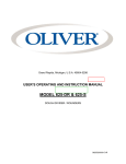
USER’S OPERATING AND INSTRUCTION MANUAL
MODEL 709
MINI SUPREME
BREAD SLICER
0709S20000-CV
MODEL 709 MINI SUPREME BREAD SLICER
INDEX
SAFETY INSTRUCTIONS.......................................................................... 0709S20025
DEFINITIONS ........................................................................................... GEN 931118
INSTALLATION INSTRUCTIONS ............................................................. 0709S20026
SPECIFICATIONS .................................................................................... 0709S20027
OPERATING INSTRUCTIONS.................................................................. 0709S20028
ADJUSTMENTS........................................................................................ 0709S20029
Slices Vary In Thickness .............................................................. 0709S20029-1/3
Limit Switch and Actuating Flag Adjustment.................................. 0709S20029-2/3
MAINTENANCE ......................................................................................... 0709S20030
Removing Blade Frames ...............................................................
Replacing Blade Frames ...............................................................
Changing Blades ...........................................................................
Lubrication........... ..........................................................................
Cleaning...... ..................................................................................
0709S20030-1/4
0709S20030-2/4
0709S20030-3/4
0709S20030-4/4
0709S20030-4/4
TROUBLE SHOOTING ............................................................................. 0709S20031
The Slicer Will Not Start ................................................................
Motor Runs But Blade Frames Do Not Move ................................
The Slicer Will Not Stop ................................................................
The Slicer Starts But Stops Too Soon ...........................................
Bread Slices Vary In Thickness .....................................................
0709S20031-1/2
0709S20031-1/2
0709S20031-1/2
0709S20031-2/2
0709S20031-2/2
WIRING DIAGRAMS ................................................................................ 0709S20032
1 Phase, 60 Hertz, 115 VAC ......................................................... 0709S20032-1/2
1 Phase, 60 Hertz, 230 VAC ......................................................... 0709S20032-2/2
1 Phase, 50 Hertz, 220 VAC ......................................................... 0709S20032-2/2
RECOMMENDED SPARE PARTS ............................................................ 0709S20033
ASSEMBLY DRAWINGS .......................................................................... 0709S20044
FRAME.............................................................................................................. 1/15
BLADE FRAMES................................................................................................ 4/15
WORKING PARTS.............................................................................................. 8/15
PUSHER ……………………………………………………………………………... 12/15
ELECTRICAL…………………………………………………………………………..15/15
REPLACEMENT PARTS LIST .................................................................. 0709S20034
WARRANTY.............................................................................................. GEN 040228
WARRANTY PROCEDURE....................................................................
GEN 040226
RETURN PARTS POLICY......................................................................
GEN 040227
REV. 7/26/10
0709S20024
MODEL 709 MINI SUPREME BREAD SLICER
SAFETY INSTRUCTIONS
Every effort has been made by Oliver Products Company to provide you with a safe
machine. However, it is essential that machine operators and maintenance personnel
observe the following safety precautions.
1. Read this manual before attempting to operate your slicer. Never allow an untrained
person to operate this machine.
2. Make sure that the machine is only connected to a properly grounded electrical
supply source of sufficient capacity for the load the slicer will put on it. Always
unplug the machine when it is not in use.
3. Always make sure the machine has been disconnected from the power supply
before cleaning or servicing.
4. Always keep your hands away from the moving parts of the machine while it is in
operation
5. All guards must be in place before starting the machine.
6. Do not wear loose fitting clothing while operating the machine. Shirt tails should be
tucked in.
7. To prevent injury handle knife blades with care and never touch moving knives.
8. Use only proper replacement parts.
In addition to these general safety instructions, also follow the more specific safety
instructions given for the different areas of the machine in the operating instructions.
0709S20025
GENERAL
DEFINITIONS
The use of the words WARNING, CAUTION, and NOTE in this manual should be guided
by the following.
WARNING
AN OPERATING PROCEDURE, TECHNIQUE, ETC., WHICH MAY
RESULT IN PERSONAL INJURY IF NOT CAREFULLY FOLLOWED.
CAUTION
AN OPERATING PROCEDURE, TECHNIQUE, ETC., WHICH MAY
RESULT IN DAMAGE TO EQUIPMENT IF NOT CAREFULLY FOLLOWED.
NOTE
AN OPERATING PROCEDURE, TECHNIQUE, ETC., WHICH IS CONSIDERED
ESSENTIAL TO EMPHASIZE.
GEN931118
MODEL 709 MINI SUPREME BREAD SLICER
INSTALLATION INSTRUCTIONS
WARNING
THE SLICER IS HEAVY. USE PROPER LIFTING TECHNIQUES, KEEP
BACK STRAIGHT, KNEES BENT, AND LIFT WITH YOUR LEGS. USE
GLOVES TO PROTECT YOUR HANDS.
Lift the slicer from its resting surface with one person standing on each end of the slicer,
(front and back), set the slicer onto the counter or table as close as possible to its
desired location.
CAUTION
BEFORE PLACING THE SLICER ON A TABLE OR COUNTER, MAKE SURE
THE TABLE OR COUNTER CAN SUPPORT THE SLICER’S WEIGHT WHICH
IS APPROXIMATELY 115 POUNDS.
Should the machine not be in its desired location, carefully slide the machine to its final
location.
The machine may now be connected to a properly grounded power supply of the same
voltage and of sufficient capacity for the load which the slicer will put on it. See the
electrical requirements on the “Oliver Nameplate” on the rear of the machine. DO NOT
USE EXTENSION CORDS.
WARNING
BEFORE ATTEMPTING TO SLICE BREAD READ THE “OPERATION”
SECTION OF THIS MANUAL.
0709S20026
MODEL 709 MINI SUPREME BREAD SLICER
SPECIFICATIONS
•
Weight: (Approximate) ----------------------------------------------------------- (115) pounds
•
Slice Spacings:
Standard ---------------------------------------------------------------------------------------- 1/2”
Available at extra cost ------------------------------------ 3/8” (min.), 7/16”, 5/8”, 3/4”, 1”
Others --------------------------------------------------------------------------- Consult Factory
•
Standard Electrical Service: --------------------
•
Optional Electrical Services: --------------------------------------------------- Consult factory
•
Product Capacities:
1/5 HP, 1-60-115 Volts AC, 2 Amps.
Length -------------------------------------------------------------------------------------- 14-5/8”
*Width --------------------------------------------------------------------------------------- 5-1/4”
*Height -------------------------------------------------------------------------------------- 5-1/4”
NOTE
*WIDTH AND HEIGHT DIMENSIONS ARE FOR A SQUARE PRODUCT.
LOWER AND WIDER PRODUCTS MAY ALSO BE SLICED BY TAKING
CARE IN LOADING THE PRODUCT. INDIVIDUAL DETERMINATIONS
WOULD HAVE TO BE MADE.
•
Machine dimensions:
Revised 6-14-07
0709S20027
MODEL 709 MINI SUPREME BREAD SLICER
OPERATING INSTRUCTIONS
WARNING
ALWAYS USE CARE WHENEVER WORKING NEAR THE CUTTING KNIVES.
To operate the machine, stand in front of the machine and grasp the lever with your right
hand. Pull the lever from its lowest position to the upper limit of its travel. Using your left
hand, load the product into the machine.
WARNING
NEVER START THE MACHINE BEFORE LOADING THE PRODUCT.
Make sure that the product does not hang over either edge of the cradle. While holding
the lever in the upper-most position, (the machine will not start unless this is done),
push the START button with your left hand.
NOTE
ONCE THE MACHINE HAS BEEN STARTED, THE MACHINE CAN BE
STOPPED BY PUSHING THE “STOP” BUTTON.
After starting, move the lever downward slowly until the product contacts the knives.
Once the product has contacted the knives move the handle down using moderate force
to slice the bread.
CAUTION
EXCESSIVE DOWNWARD FORCE SHOULD NOT BE USED AS DAMAGE
TO THE MACHINE OR PRODUCT MAY RESULT.
When the slicing operation is complete, and the handle is at its lowest position, the
machine will automatically stop. The cradle will stay in the upper most position so that
both hands can be used to grasp the sliced product and remove it from the top of the
cradle. The product can then be moved to the bagging scoop mounted on the front of
the machine which will ease packaging of your product.
0709S20028
MODEL 709 MINI SUPREME BREAD SLICER
ADJUSTMENTS
WARNING
ALWAYS UNPLUG THE SLICER WHEN ADJUSTING OR SERVICING.
•
Slices Vary In Thickness:
NOTE
IN ONLY THREE SITUATIONS SHOULD IT BECOME NECESSARY TO
ADJUST THE BLADE FRAMES FOR A VARIANCE IN SLICE THICKNESS.
1. IF THE BLADE FRAME GUIDE BARS BECOME LOOSE ALLOWING
THE FRAME TO MOVE.
2. IF THE BLADE FRAMES WERE REMOVED FROM THE MACHINE
AND REPLACED IN OPPOSITE POSITIONS.
3. THE BLADE FRAMES ARE BEING REPLACED WITH A DIFFERENT
SET OF BLADE FRAMES, SUCH AS IN A CONVERSION TO A
DIFFERENT SLICE WIDTH.
To correct the variance in slice thickness, remove the front and top covers which are
each held in place with four screws.
NOTE
A TABLE LIP IS ATTACHED BETWEEN THE TOP COVER AND THE
INFEED TABLE BY FRICTION, A SLIGHT PULL MAY BE REQUIRED
TO DISLODGE IT.
Next remove the lower screw from the holddown pivot block on each side of the
machine, also loosen the upper screw of the pivot block, but, do not remove it. When
this has been done you will be able to pivot the holddown out of the knives to allow
removal of the blade frames. Next remove the shoulder screw from the foot of the top
blade frame, (the blade frame is connected to the rocker through a pivoting link on the
foot of the blade frame). Once disconnected the top blade frame can be removed by
sliding the frame forward out of the tracks.
WARNING
ALWAYS USE CARE WHENEVER WORKING NEAR THE CUTTING KNIVES.
0709S20029-1
MODEL 709 MINI SUPREME BREAD SLICER
•
Slices Vary In Thickness: (Cont’d.):
At this point check the side to side movement of the lower blade frame: it should be at
the minimum which still allows free travel in the tracks. If the side to side movement
seems satisfactory check the centering of the frame. The distance from the side of the
blade frame to the machine’s side should be as close as possible to the same distance
on each side.
Should either of the above two situations need correction loosen the four nuts, two on
each side, which secure the lower blade frame guide bars, (they are accessible from the
underside of the blade frame). Once loosened, the blade frame can be centered in the
machine, making sure that the guide bars are as far into the tracks as they will go, thus
limiting side to side movement. When the bars are as far into the tracks as reasonably
possible and the blade frame is centered in the machine, re-tighten the nuts. Re-check
the blade frame for proper centering, side to side movement and ease of travel.
When the lower blade frame has been found to be in its proper position, or, corrected to
the proper position, (if that was required), as described previously, re-install the upper
blade frame. Replace the shoulder screw and link at the foot of the blade frame,
replacing and tightening the nut and lock washer which secure the shoulder screw.
Check the distance between any three adjacent blades using a 12 inch or shorter ruler.
the outside blades should be the same distance from the center blade. If this is the case
the slices will be the same thickness, if the distance varies then the upper blade frame
must be adjusted side to side until the measured distances are equal.
To adjust the upper blade frame loosen the four nuts, (two on each side), which secure
the blade frame guide bars. Once loosened the blade frame can be adjusted by moving
it slightly either right or left in the machine until the distances as measured above are
equal. Make sure the guide bars are as far into the tracks as they will go to limit side to
side movement. When the bars are as far into the tracks as possible and the blade
spacing is equal, re-tighten the nuts. Re-check the blade frame for proper spacing, side
to side movement and ease of travel.
Rotate the holddown back into the knives. Replace and secure the four mounting
screws of the pivot blocks and replace the front and top covers securing each with the
four screws which were previously removed.
•
Limit Switch and Actuating Flag Adjustment:
After disconnecting the slicer from the power supply, remove the rear cover from the
machine allowing access to the limit switch area.
•
Limit Switch and Actuating Flag Adjustment (Cont’d.):
0709S20029-2
MODEL 709 MINI SUPREME BREAD SLICER
The actuating flag should trip the lower limit switch when the cradle handle is at the top
of its travel. The upper limit switch should be actuated when the cradle handle is at the
bottom of its travel. The tripping point of a limit switch can be detected by an internal
clicking sound made by the switch. Before attempting to adjust the flag or switches
make sure that the switch levers have not been bent, or, the switch otherwise damaged,
or, that the actuating flag is not just loose on the shaft.
Should switch adjustment be necessary they should be adjusted so that they are tripped
during normal movement of the cradle handle just before either end of the handle’s
travel.
To adjust either of the limit switches or the actuating flag, use the following procedure.
Loosen the set screw in the actuating flag allowing it to rotate easily on the shaft. With
the cradle handle in its upper most position, loosen both of the screws securing the
lower limit switch. Once loosened move the switch until it is approximately in the center
of its travel and re-tighten the switch. Move the loosened actuating flag into the lower
switch lever until you hear it trip. Tighten the flag’s set screw. Re-check the operation of
the switch using the cradle handle. It should function as described above.
Should the upper limit switch need adjustment, (after setting the lower switch as
described above), loosen the two screws which secure it in position and with the cradle
handle in its lowest position move the switch into the flag until you hear it trip. Re-tighten
the screws and re-check the switch operation as before.
0709S20029-3
MODEL 709 MINI SUPREME BREAD SLICER
MAINTENANCE
WARNING
ALWAYS UNPLUG THE SLICER BEFORE PERFORMING ANY TYPE
OF MAINTENANCE TASK.
•
Removing Blade Frames:
Remove the top and front covers by removing the four screws which holds each in place.
The table lip should be removed with the top cover.
NOTE
A TABLE LIP IS ATTACHED BETWEEN THE TOP COVER AND THE
INFEED TABLE BY FRICTION, A SLIGHT PULL MAY BE REQUIRED
TO DISLODGE IT.
Next remove the lower screw from the holddown pivot block on each side of the
machine, also loosen the upper screws of the pivot blocks but do not remove them.
When this has been done you will be able to pivot the holddown out of the knives to
allow removal of the blade frames.
Remove the upper blade frame by removing the shoulder screw from the foot of the
blade frame, (the blade frame is connected to the rocker by means of a plastic link at the
“Foot” of the blade frame). Once the shoulder screw and link have been removed the
blade frame can be slid forward and removed from the tracks and from the machine.
WARNING
THE BLADES ARE EXTREMELY SHARP. ALWAYS HANDLE THE
BLADE FRAMES WITH CARE.
To remove the lower blade frame, (see note below), you must first remove the four
screws from the infeed table. While this table does not have to be removed from the
machine it must be moved down out of the way to allow removal of the lower blade
frame.
NOTE
REMOVAL OF THE LOWER BLADE FRAME IS NOT REQUIRED TO
CHANGE ITS BLADES.
0709S20030-1
MODEL 709 MINI SUPREME BREAD SLICER
•
Removing Blade Frames (Cont’d.):
The final step is to remove the shoulder screw from the foot of the blade frame. Once
the shoulder screw is removed the link can be disconnected and moved out of the way.
This will allow removal of the lower blade frame.
•
Replacing Blade Frames:
To replace the blade frames, reverse the removal procedures, (described above). Reinstall both blade frames and check for slice thickness variances. If the spaces between
all blades are not the same see the “Adjustment” section of this manual. If the spacing
is equal, if there is little side to side movement of the blade frames and they move freely
in the tracks, re-connect the links at the foot of each blade frame by re-installing the
shoulder screw. Replace the lockwasher and nut on each shoulder screw and tighten
securely.
Replace the infeed table and secure it in position by installing its four screws. Rotate the
holddown back into the knives and replace and/or tighten their mounting screws.
Replace the table lip making sure it does not rub on the sides of the blades where the
blades pass thorough it. Lastly replace the top and front covers securing them in place
using the four screws previously removed from each.
0709S20030-2
MODEL 709 MINI SUPREME BREAD SLICER
•
Changing Blades:
WARNING
BLADES ARE EXTREMELY SHARP. ALWAYS HANDLE WITH CARE.
Remove and place the Upper blade frame on a flat surface, (see blade frame removal
section). Insert the special knife tool into the blade frame, (See Illustration). Lifting up
on the knife tool will deflect the blade mount, reducing tension on the cutting knife.
Carefully remove the cutting knife from the blade mount.
NOTE
REMOVAL OF THE LOWER BLADE FRAME IS NOT REQUIRED TO
CHANGE ITS BLADES.
NOTE
WHEN REPLACING ALL THE BLADES, ALWAYS REMOVE THE CENTER
BLADES FIRST AND WORK TOWARDS THE ENDS. REMOVE AND INSTALL
ONE BLADE AT A TIME, NEVER REMOVE ALL THE BLADES AT ONCE
AND THEN ATTEMPT TO REPLACE THEM ALL AT ONCE.
0709S20030-3
MODEL 709 MINI SUPREME BREAD SLICER
•
Changing Blades (Cont’d.):
Reverse the procedure to install replacement blades. A paper clip can be used to hold
the blade in position on the fixed blade mount during blade installation. (See Illustration)
The blades can be removed and replaced from the lower blade frame while it is in the
machine. Use the same tool and similar procedures as described in removing an
replacing blades from the upper blade frame.
Upon completion of the blade changes re-install and secure all parts removed, (refer to
the blade frame removal section above).
•
Lubrication:
The blade frame tracks, the four shoulder screws at the links connecting the blade frame
and the rocker and the cradle guide tracks have been lubricated at the factory. Twice a
year, or, sooner if they become dry, the above areas should be greased with a food
approved grease.
•
Cleaning:
Use a mild detergent solution to clean the exterior and contact surfaces. Empty the
crumb tray daily or as necessary. Periodically remove all covers and brush, vacuum or
blow, (if compressed air is available), all foreign material from all surfaces, especially the
moving parts.
0709S20030-4
MODEL 709 MINI SUPREME BREAD SLICER
TROUBLE SHOOTING
•
The Slicer Will Not Start When the “Start” Button Is Pushed:
Possible Causes:
1. The slicer is not plugged in.
2. The fuse or circuit breaker in the back of the machine has either blown or tripped.
3. The outlet to which the slicer is plugged in is not functioning: have it checked by a
qualified electrician.
4. The pusher handle is not in the upper most position and is therefore not tripping the
internal start limit switch.
5. The actuating flag has become loose: see adjustment section of this manual.
6. If the pusher handle is in its upper most position, (see #3 above), then the internal
start limit switch may need adjustment. Refer to the adjustment section of this
manual.
7. The “Start” push-button switch is not operating: have it checked by a qualified
electrician.
8. The relay is not operating: have it checked by a qualified electrician.
9. A loose wire is preventing the machine from operating. Unplug the slicer remove the
rear panel and check all connections.
10. An internal limit switch has failed: have them checked and replaced if necessary by
a qualified electrician.
11. The gearmotor is not operating: a qualified electrician should check the gearmotor
and its start capacitor, and replace if defective.
12. The “Stop” push-button has failed: have it checked by a qualified electrician.
•
The Motor Starts and Runs But the Blade Frames Do Not Move:
Possible Causes:
1. The connecting rods have either become un-attached or broken.
•
The Slicer Starts But Will Not Automatically Stop At the Completion of Slicing:
Possible Causes:
1. The pusher handle is not in its lowest position and is therefore not tripping the
internal stop limit switch.
2. The actuating flag is either loose or incorrectly adjusted. See the adjustment section
of this manual.
3. The internal stop limit switch has failed: have it checked and replaced if required by
a qualified electrician.
Revised 3-25-98
0709S20031-1
MODEL 709 MINI SUPREME BREAD SLICER
TROUBLE SHOOTING (CONT’D.)
•
The Slicer Will Start, But, Will Not Continue To Run:
Possible Causes:
1. The relay is not operating: have it checked by a qualified electrician.
2. One of the internal limit switches have become loose and is out of position. See the
adjustment section of this manual.
3. A internal limit switch has failed: have them checked and replaced if necessary by a
qualified electrician.
•
Bread Slices Vary In Thickness:
Possible Causes:
1. The blade frames should be adjusted, see the adjustment section of this manual.
Revised 3-25-98
0709S20031-2
MODEL 709 MINI SUPREME BREAD SLICER
WIRING DIAGRAMS
NOTE
SELECT WIRING DIAGRAMS BASED ON THE MOTOR MODEL
FURNISHED ON YOUR MACHINE AND THE ELECTRICS OF YOUR
MACHINE.
“Dayton” Motor Wired as 1 Phase, 60 Hertz, 115 Volts AC
Wiring Diagram 0709C12012
“Leeson” Motor Wired as 1 Phase, 60 Hertz, 115 Volts AC
Wiring Diagram 0709C12013
0709S20032-1
MODEL 709 MINI SUPREME BREAD SLICER
WIRING DIAGRAMS (Cont’d.)
“Leeson” Motor Wired as 1 Phase, 60 Hertz, 230 Volts AC
Wiring Diagram 0709C12014
“Leeson” Motor Wired as 1 Phase, 50 Hertz, 220 Volts AC
Wiring Diagram 0709C12015
0709S20032-2
MODEL 709 MINI SUPREME BREAD SLICER
RECOMMENDED SPARE PARTS
PART NUMBER
5251-8090
0709-0035-001
5251-3022
5842-8525
5251-0091
5915-9815
0709-0038
0797-0029-1
5842-8526
5749-8027
5749-8028
5726-1030
5757-7610
5757-7651
0709-0080
0709-0078
5757-8001
0709-0034-XXX
PART DESCRIPTION
Bearing-Pillow Block
Link-Blade Frame
Bearing-2 Bolt Flange
Screw-Shoulder 3/8 X 1”
Bearing-Cam Follower
Plunger-Ball
Bushing-Flange
Blade-Type “A”
Screw-Shoulder 3/8 X 1-1/4
Relay-DPST 20A 240 VAC 120V Coil
Relay-DPST 20A 240 VAC 230V Coil
Holder-Fuse
Switch-Push Button
Bezel-Square Silver
Button-Square Black
Button-Square Red
Switch-Limit
* Rod-Long Connecting
NO. REQ’D.
2
2
2
5
2
1
2
As Req’d.
1
1
1
1
2
2
1
1
2
1
* Dependent on model of motor used -- see “Part List” which follows
OPTIONAL SPARE PARTS
NOTE
A GEARMOTOR WOULD BE CONSIDERED AN OPTIONAL SPARE
PART. GEARMOTORS SHOULD BE SELECTED BASED ON THE
MODEL FURNISHED ON YOUR MACHINE AND THE ELECTRICS OF
YOUR MACHINE AS INDICATED BELOW.
6310-0250
Dayton Motor (115 VAC)
1
6310-1910
Leeson Motor (115 VAC)
1
0709-0054-004
Leeson Motor (220/230 VAC)
1
To obtain Replacement parts call Oliver Products Company at 1-800-253-3893
REVISED 3-25-98
0709S20033
MODEL 709 MINI SUPREME BREAD SLICER
FRAME
REV. 6/9/09
1/15
0709S20044
MODEL 709 MINI SUPREME BREAD SLICER
B-NO.
PART DISCRIPTION
PART NO.
QTY.
1
BAR-CROSS TOP
0709-0027
2
2
BAR-CROSS REAR
0709-0027-001
1
3
BAR-CROSS REAR BOTT.
0709-0027-002
1
5
BAR-STUB
0709-0028
2
6
SCOOP-BAGGING
0709-0029
1
7
SIDE-RH
0709-0032
1
8
SIDE-LH
0709-0033
1
9
SPACER-SCOOP END
0711-0006
1
33
SCREW-SLTD
5843-5385
2
34
SCREW-SLTD
5843-5412
12
104
SPACER-HEX
0709-0039
1
504
LIP-TABLE
0709-0081-0XX
1
605
COVER-FRONT
0709-0030-1
1
606
COVER-REAR
0709-0031
1
607
CLIP-FINGER RH
0709-0042
1
608
CLIP-FINGER LH
0709-0043
1
To obtain Replacement Parts call Oliver Products Company at 1-800-253-3893
2/15
0709S20044
MODEL 709 MINI SUPREME BREAD SLICER
B-NO.
PART DISCRIPTION
PART NO.
QTY.
618
COVER-BOTTOM
0709-0069
1
801
SUBPANEL
0709-0036
1
804
SWITCH-PB-SNP
5757-7610
2
805
BUTTON-RED SQ. “STOP”
0709-0078
1
806
BEZEL-SQR SILVER
5757-7651
2
809
BLACK START BUTTON
0709-0080
1
To obtain Replacement Parts call Oliver Products Company at 1-800-253-3893
3/15
0709S20044
MODEL 709 MINI SUPREME BREAD SLICER
BLADE FRAMES
4/15
0709S20044
MODEL 709 MINI SUPREME BREAD SLICER
B-NO.
PART DISCRIPTION
PART NO.
QTY
2
BAR-CROSS REAR
0709-0027-001
1
3
BAR-CROSS REAR-BOTT.
0709-0027-002
1
4
BAR-FRONT
0709-0027-003
1
10
BUMPER-BLK HRD RUBR
5902-0021
4
11
WASHER-LOCK 1/4"
5851-9357
4
12
SCREW-HEX HD 1/4-20
5843-1006
2
13
SCREW-HEX HD 1/4-20
5843-1005
2
51
SCREW-SLTD TRSHD
5843-5414
8
53
SCREW-SHOULDER 3/8 X 1
5842-8525
5
54
WASHER-5/16 INTYP LOCK
5851-9134
5
55
NUT-HEX JAM5/16-18
5832-0001
5
58
BOLT-CARRIAGE 3/8-16
5804-1710
4
59
WASHER-3/8 SPRING LCK
5851-9359
4
60
NUT-HEX FULL 3/8-16
5832-0522
4
61
SCREW-HEX HEAD 1/4-20
5842-1506
4
62
WASHER 1/4" SPRNG LCK
5851-9008
5
63
SCREW-SOCET HD 10-24
5842-2533
1
To obtain Replacement Parts call Oliver Products Company at 1-800-253-3893
5/15
0709S20044
MODEL 709 MINI SUPREME BREAD SLICER
B-NO.
PART DISCRIPTION
PART NO.
QTY
64
SCRW-HX HD 1/4-20
5842-1502
1
66
SCREW-SLTD
5843-5413
6
67
BOLT-CARRIAGE 1/4-20
5804-0615
8
68
NUT-HEX FULL 1/4-20
5832-0025
8
69
SCREW-SHOULDER 3/8
5842-8526
1
70
WASHR-SPRNG LOCK WSH 5851-9009
1
71
NUT HEX JAM5/16-18
5832-0001
1
72
NUT-ACORN 1/4-20
5832-0590
2
101
SPACER BEARING
0709-0009
2
102
HANDLE & GEAR ASSY.
0709-0011-1
1
103
PLATE-MOTOR MTG.
0709-0023
1
105
PUSHER ARM ASSY
0709-0046-1
1
106
ANCHOR BRACKET
0709-0079
1
107
BEARING-PILLOW BLOCK
5251-8090
2
108
RING-RETAINING TRUARC 5840-1125
1
109
KNOB-BALL
1
5911-7001
To obtain Replacement Parts call Oliver Products Company at 1-800-253-3893
6/15
0709S20044
MODEL 709 MINI SUPREME BREAD SLICER
B-NO.
PART DISCRIPTION
PART NO.
QTY
110
SPRING-EXTENSION STST
7022-4113
1
201
TRACK-BLADE FRAME
0709-0007
2
202
ROCKER
0709-0008
1
203
LINK BLADE FRAME
0709-0035-001
2
204
SPACER BEARING
0709-0041
4
206
BEARING-FLANGE BALL
5251-3022
2
406
INSERT-THREAD1/4-20
5822-2030
8
501
BLADE FRAME (SPACING)
0709-0001-5XX
-
502
BAR-GUIDE
0709-0006
4
507
BLADE-TYPE A
0797-0029-1
-
610
BRACKET-TRAY CENTER
0709-0053
2
701
CRANK MOTOR
0709-0010-002
1
702
ROD-CONNECTING LONG
0709-0034-003
1
706
GEARMOTOR 1/5 HP
6310-1910
1
To obtain Replacement Parts call Oliver Products Company at 1-800-253-3893
7/15
0709S20044
MODEL 709 MINI SUPREME BREAD SLICER
WORKING PARTS
8/15
0709S20044
MODEL 709 MINI SUPREME BREAD SLICER
B-NO.
PART DISCRIPTION
PART NO.
QTY
11
WASHER-LOCK 1/4"
5851-9357
4
13
SCREW-HEX HD 1/4-20
5843-1005
2
53
SCREW-SHOULDER 3/8 X 1
5842-8525
5
54
WASHER-5/16 INTYP LOC
5851-9134
7
55
NUT-HEX JAM5/16-18
5832-0001
7
58
BOLT-CARRIAGE 3/8-16
5804-1710
4
59
WASHER-3/8 SPRNG LOCK
5851-9359
4
60
NUT-HEX FULL 3/8-16
5832-0522
4
61
SCREW-HEX HEAD 1/4-20
5842-1506
1
62
WASHER-1/4" SPRNG LOK
5851-9008
1
68
SCREW-HEX HEAD 3/8-16
5842-1555
1
69
SCREW-SHLDER 3/8 X 1 ¼
5842-8526
1
70
SCREW-SOC HD 1/4-20 X 1
5842-2545
4
71
SCREW-ROUND HD 1/4-20
5842-5104
2
73
SCREW-HEX HD 1/4-20
5843-1001
2
77
SCREW-HXSOC HD1/4-20
5843-1542
2
To obtain Replacement Parts call Oliver Products Company at 1-800-253-3893
9/15
0709S20044
MODEL 709 MINI SUPREME BREAD SLICER
B-NO.
PART DISCRIPTION
PART NO.
QTY
101
SPACER BEARING
0709-0009
2
102A
LEVER
0709-0011-0023
1
102B
GEAR-SPUR 68T
0709-0011-0033
1
102C
STUD-PIVOT
0709-0011-0013
1
105A
ARM-PUSHER
0709-0046-0023
2
105B
ACTUATOR-SWITCH
0709-0046-0034
1
105C
SHAFT
0709-0046-0073
1
105D
GEAR 44T
0709-0046-0093
1
105E
BLOCK PIVOT
0709-0046-0083
2
105F
BEARING-SINT BRZ
5254-0322
2
105G
COLLAR
0709-0046-0063
1
106
ANCHOR BRACKET
0709-0079
1
107
BEARING-PILLOW BLK
5251-8090
2
109
KNOB-BALL
5911-7001
1
110
SPRING-EXTENSION
7022-4113
1
202
ROCKER
0709-0008
1
To obtain Replacement Parts call Oliver Products Company at 1-800-253-3893
10/15
0709S20044
MODEL 709 MINI SUPREME BREAD SLICER
B-NO.
PART DISCRIPTION
PART NO.
QTY
203
LINK-BLADE FRAME
0709-0035-001
2
204
SPACER BEARING
0709-0041
4
206
BEARING-FLANGE BALL
5251-3022
2
701
CRANK MOTOR
0709-0010-002
1
702
ROD-CONNECTING LONG
0709-0034-003
1
703
SHIELD-CRUMB
0709-0047-001
1
704
BEARING-SN BZ
5254-3503
1
706
GEARMOTOR 1/5 HP
6310-1910
1
801
SUBPANEL
0709-0036
1
To obtain Replacement Parts call Oliver Products Company at 1-800-253-3893
11/15
0709S20044
MODEL 709 MINI SUPREME BREAD SLICER
PUSHER
12/15
0709S20044
MODEL 709 MINI SUPREME BREAD SLICER
B-NO.
PART DISCRIPTION
PART NO.
5
BAR-STUB
0709-0028
11
WASHER-LOCK 1/4"
5851-9357
13
SCREW-HEX HD 1/4-20
5843-1005
34
SCREW-SLTD TRSHD
5843-5412
53
BEARING-CAM
5251-0091
56
BOLT-CARRIAGE 1/4-20
5804-1706
57
BOLT-CARRIAGE 1/4-20
5804-1709
58
WASHER-1/4" FLAT
5851-9304
60
NUT-HX FULL 1/4-20
5832-0520
61
NUT-ELASTC FL 1/4-20
5831-9087
66
SCREW-SLTD TRSHD
5843-5413
73
SCREW-HEX HD 1/4-20
5843-1001
81
SCREW-FLAT HD 1/4-20
5843-2732
301
BRACKET-CRADLE MTG
0709-0013-001
302
SPACER-PUSHER GUIDE
0709-0015
303
PLATE-BACKUP
0709-0016
QTY
To obtain Replacement Parts call Oliver Products Company at 1-800-253-3893
13/15
0709S20044
MODEL 709 MINI SUPREME BREAD SLICER
B-NO.
PART DISCRIPTION
PART NO.
304
GUIDE-PUSHER
0709-0017-002
305
BLOCK-SLIDE
0711-0017
306
GUIDE-PUSHER W/BOSS
0709-0017-003
402
BLOCK-MOUNTING
0709-0037
403
BUSHING-FLANGE
0709-0038
404
SPRING-L.H. TORSION
4605-1000-0014
405
SPRING-R.H. TORSION
4605-1000-0015
406
INSERT-THREAD1/4-20
5822-2030
407
COLLAR-SPRING
0709-0057
503
KNIFE GUIDE & HLDDWN
0709-0082-0XX
506
CRADLE
0709-0045-XXX
601
TABLE-INFEED
0709-0018
603
BRACKET-TBLE MTG RH
0709-0025
604
BRACKET-TBLE MTG LH
0709-0026
QTY
To obtain Replacement Parts call Oliver Products Company at 1-800-253-3893
14/15
0709S20044
MODEL 709 MINI SUPREME BREAD SLICER
ELECTRICAL PANEL
B-NO.
PART DISCRIPTION
PART NO.
801
SUBPANEL
0709-0036
1
803
RELAY-DPST 20A 120/240V
5749-8027
1
807
SWITCH – SM BASIC
5757-8001
2
15/15
QTY
0709S20044
MODEL 709 MINI SUPREME BREAD SLICER
REPLACEMENT PARTS LIST
ITEM NO.
001
002
003
004
005
006
007
008
009
010
101
102
103
104
105
106
107
108
109
110
201
202
203
204
205
206
207
208
301
302
303
304
305
306
307
308
309
402
403
404
405
PART DESCRIPTION
Bar-Top Cross
Bar-Rear Cross
Bar-Rear Bottom Cross
Bar-Front
Bar-Stub
Scoop-Bagging
Side-R.H.
Side-L.H.
Spacer-Scoop
Foot-Rubber
Spacer-Bearing
Handle & Gear Assembly
Plate-Motor Mounting
Spacer-Hex
Pusher Arm Assembly
Bracket-Anchor
Bearing-Pillow Block
Ring-Retaining
Knob-Ball
Spring-Extension
Track-Blade Frame
Rocker
Link-Blade Frame
Spacer-Bearing
Bearing-2 Bolt Flange
Bearing-Thrust
Insert-Threaded Brass
Screw-Shoulder 3/8 x 1”
Bracket-Cradle Mounting
Spacer-Pusher Guide
Plate-Backup
Guide-Pusher
Guide-Pusher W/Boss
Block-Slide
Bearing-Cam Follower
Nut-Elastic Lock
Plunger-Ball
Kit-Mounting Block
Bushing-Flange
Spring-L.H. Torsion
Spring-R.H. Torsion
PART NUMBER
0709-0027
0709-0027-001
0709-0027-002
0709-0027-003
0709-0028
0709-0029
0709-0032
0709-0033
0711-0006
5902-0021
0709-0009
0709-0011-1
0709-0023
0709-0039
0709-0046-1
37608
5251-8090
5840-1125
5911-7001
7022-4113
0709-0007
0709-0008
0709-0035-001
0709-0041
5251-3022
5254-3542
5822-2030
5842-8525
0709-0013-001
0709-0015
0709-0016
0709-0017-002
0709-0017-003
0711-0017
5251-0091
5831-9087
5915-9815
0709-0037K
0709-0038
4605-1000-0014
4605-1000-0015
To obtain Replacement Parts call Oliver Products Company at 1-800-253-3893
REV 6/23/05
0709S20034-1
MODEL 709 MINI SUPREME BREAD SLICER
PARTS LIST (Cont’d.)
ITEM NO.
407
501
502
503
504
506
507
508
509
601
603
604
605
606
607
608
609
610
618
701
702
703
704
705
706
801
802
803
803
804
805
806
807
808
809
810
810
810
810
811
811
811
PART DESCRIPTION
PART NUMBER
Collar-Spring
0709-0057
Blade Frame (Specify slice width)
0709-0001-5XX
Bar-Guide
0709-0006
Holddown-Knife Guide (Specify slice width)0709-0082-0XX
Lip-Table & Cover (Specify slice width)
0709-0081-0XX
Cradle-Bread (Specify slice width)
0709-0045-2XX
Blade-Type “A” (As Required)
0797-0029-1
Tool-Knife
0797-0183-005
Nut-Elastic Lock
5831-9095
Table-Infeed
0709-0018
Bracket-R.H. Table Mounting
0709-0025
Bracket-L.H. Table Mounting
0709-0026
Cover-Front
0709-0030
Cover-Rear
0709-0031
Clip-R.H. Finger
0709-0042
Clip-L.H. Finger
0709-0043
Tray-Crumb
0709-0052-001
Bracket-Tray Centering
0709-0053
Cover-Bottom
0709-0069
See Next 2 Pages
-------------See Next 2 Pages
-------------Shield-Crumb
0709-0047-001
Bearing-Thrust
5254-3503
Screw-Shoulder 3/8 x 1-1/4
5842-8526
See Next 2 Pages
-------------Subpanel
0709-0036
Harness-Push-button
0709-0049-3
Relay-DPST 20A 240VAC 120V Coil
5749-8027
Relay-DPST 20A 240VAC 230V Coil
5749-8028
Switch-Push-button
5757-7610
Button-Square Red
0709-0078
Bezel-Square Sliver
5757-7651
Switch-Limit
5757-8001
Bushing-Strain Relief
5765-1076
Button-Square Black
0709-0080
Holder-Fuse
5726-1030
Breaker-Circuit 2 Amp
5757-4105
Breaker-Circuit 3 Amp
5757-4155
Breaker-Circuit 5 Amp
5757-4255
Fuse-1.5 Amp
5725-9121
Fuse-3 Amp
5725-9126
Fuse-5 Amp
5725-9127
To obtain Replacement Parts call Oliver Products Company at 1-800-253-3893
Rev. 6/22/05
0709S20034-2
MODEL 709 MINI SUPREME BREAD SLICER
NOTE
THE FOLLOWING COMPONENTS MUST BE SELECTED BASED ON THE
MODEL OF GEARMOTOR AND THE ELECTRICS USED ON YOUR SLICER.
“Dayton” Motor wired as 1 Phase, 60 Hertz, 115 Volts AC
ITEM NO.
701
702
706
-----
PART DESCRIPTION
Crank-Motor
Rod-Long Connecting
Motor-Gear
Cord-Motor
Cord-Power
PART NUMBER
0709-0010
0709-0034-001
6310-0250
0709-0044-101
0709-0056-007
“Leeson” Motor wired as 1 Phase, 60 Hertz, 115 Volts AC
ITEM NO.
701
702
706
---
PART DESCRIPTION
Crank-Motor
Rod-Long Connecting
Motor-Gear
Cord-Power
PART NUMBER
0709-0010-002
0709-0034-003
6310-1910
0709-0056-007
“Leeson” Motor wired as 1 Phase, 60 Hertz, 230 Volts AC
ITEM NO.
701
702
706
-----
PART DESCRIPTION
Crank-Motor
Rod-Long Connecting
Motor-Gear
Cord-Power
Cap-Plug 3-Wire 250 VAC
PART NUMBER
0709-0010-002
0709-0034-003
0709-0054-004
0709-0056-005
5765-2030
“Leeson” Motor wired as 1 Phase, 50 Hertz, 220 Volts AC
ITEM NO.
701
702
706
---
PART DESCRIPTION
Crank-Motor
Rod-Long Connecting
Motor-Gear
Cord-Power
PART NUMBER
0709-0010-002
0709-0034-003
0709-0054-004
0709-0056-006
REV. 5-24-00
0709S20034-3
WARRANTY
PARTS
Oliver Packaging & Equipment Company (Oliver) warrants that if any part of the equipment (other
than a part not manufactured by Oliver) proves to be defective (as defined below) within two years
after shipment, and if Buyer returns the defective part to Oliver within one year, Freight Prepaid to
Oliver’s plant in Grand Rapids, MI, then Oliver, shall, at Oliver’s option, either repair or replace the
defective part, at Oliver’s expense.
LABOR
Oliver further warrants that equipment properly installed in accordance with our special instructions,
which proves to be defective in material or workmanship under normal use within one (1) year from
installation or one (1) year and three (3) months from actual shipment date, whichever date comes
first, will be repaired by Oliver or an Oliver Authorized Service Dealer, in accordance with Oliver’s
published Service Schedule.
For purposes of this warranty, a defective part or defective equipment is a part or equipment which is
found by Oliver to have been defective in materials workmanship, if the defect materially impairs the
value of the equipment to Buyer. Oliver has no obligation as to parts or components not
manufactured by Oliver, but Oliver assigns to Buyer any warranties made to Oliver by the
manufacturer thereof.
This warranty does not apply to:
1. Damage caused by shipping or accident.
2. Damage resulting from improper installation or alteration.
3. Equipment misused, abused, altered, not maintained on a regular basis, operated carelessly, or
used in abnormal conditions.
4. Equipment used in conjunction with products of other manufacturers unless such use is approved
by Oliver Products in writing.
5. Periodic maintenance of equipment, including but not limited to lubrication, replacement of wear
items, and other adjustments required due to installation, set up, or normal wear.
6. Losses or damage resulting from malfunction.
The foregoing warranty is in lieu of all other warranties expressed or implied AND OLIVER MAKES
NO WARRANTY OF MERCHANTABILITY OR FITNESS FOR PURPOSE REGARDING THE
EQUIPMENT COVERED BY THIS WARRANTY. Oliver neither assumes nor authorizes any person
to assume for it any other obligations or liability in connection with said equipment. OLIVER SHALL
NOT BE LIABLE FOR LOSS OF TIME, INCONVENIENCE, COMMERCIAL LOSS, INCIDENTAL OR
CONSEQUENTIAL DAMAGES.
GEN 040228
WARRANTY PROCEDURE
1. If a problem should occur, either the dealer or the end user must contact the Parts and
Service Department and explain the problem.
2. The Parts and Service Manager will determine if the warranty will apply to this particular
problem.
3. If the Parts and Service Manager approves, a Work Authorization Number will be
generated, and the appropriate service agency will perform the service.
4. The service dealer will then complete an invoice and send it to the Parts and Service
Department at Oliver Products Company.
5. The Parts and Service Manager of Oliver Packaging and Equipment Company will
review the invoice and returned parts, if applicable, and approve for payment.
GEN 040226
RETURNED PARTS POLICY
This policy applies to all parts returned to the factory whether for warranted credit,
replacement, repair or re-stocking.
Oliver Packaging and Equipment Company requires that the customer obtain a Return
Material Authorization (RMA) number before returning any part. This number should appear
on the shipping label and inside the shipping carton as well. All parts are to be returned
prepaid. Following this procedure will insure prompt handling of all returned parts.
To obtain an RMA number contact the Repair Parts Deptartment toll free at (800) 253-3893.
Parts returned for re-stocking are subject to a RE-STOCKING CHARGE.
Thank you for your cooperation,
Repair Parts Manager
Oliver Packaging and Equipment Company
GEN 040227
THIS PAGE WAS INTENTIONALLY
LEFT BLANK.
GEN020319