1
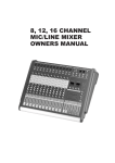
KRONUS PRO SERIES
6500 PRO, 8600 PRO
12700 PRO, 16700 PRO
User Manual / Instrucciones de Usuario
KRONUS 6500 PRO, 8600 PRO
KRONUS 12700 PRO, 16700 PRO
Powered audio mixer with 6,8,12 and 16 channels
ENGLISH MANUAL
page 1
MANUAL ESPAÑOL
página 13
This symbol on the product or on its packaging indicates that this product
shall not be trated as household waste. Instead it shall be handed over to
the applicable collection point for the recycling of electrical an electronic
equipment. By ensuring this product is disposed of correctly, you will help
prevent potential negative consequences for the environment and human
health, which could otherwise be caused by inappropriate waste handling
of this product. The recycling of amterials will help to conserve natural
resources. For more detailed information sabout recycling of this product,
please contact your local city office, your household waste disposal service
or the shop where you purchased the product.
Este símbolo en su equipo o embalaje, indica que el presente producto
no puede ser tratado como residuos domésticos normales, sino que deben
entregarse en el correspondiente punto de recogida de equipos electrónicos
y eléctricos. Asegurándose de que este producto es desechado
correctamente, Ud. está ayudando a prevenir las consecuencias negativas
para el medio ambiente y la salud humana que podrían derivarse de la
incorrecta manipulación de este producto. EL reciclaje de materiales
ayuda a conservar las reservas naturales. Para recibir más información,
sobre el reciclaje de este producto, contacte con su ayuntamiento, su
punto de recogida más cercano o el distribuidor donde adquirió el producto.
ENGLISH
KRONUS 6500 PRO, 8600 PRO
KRONUS 12700 PRO, 16700 PRO
Ultra low noise 6,8,12,16 - Channel Mic / Line Mixer
6, 8, 12, 16 Mono Input Channels with sliver plated XLRs and balanced Line Inputs
Ultra-low noise discrete Mic Preamps with +48 V Phantom Power
Ultra-musical 3-band EQ on all channels
Peak LEDs all Mono Channels
1 Aux Send per channel for external effects
Built in digital multi effect (16 DSP)
2-Track Inputs assignable to Master Mix Output
Highly accurate 10 segment Bargraph Meters
1 Stereo master output and 1 Stereo Group output
(Separate Master Mix Outputs)
SAFETY INSTRUCTIONS
CAUTION:
To reduce the risk of electrical shock, do not remove
the cover (or back). No user serviceable parts inside;
refer servicing to qualified personnel.
CAUTION
WARNING: To reduce the risk of fire or electrical shock, do not
expose this appliance to rain or moisture.
This symbol, wherever it appears, alerts
dangerous voltage inside the enclosure
you to the presence of uninsulated
- voltage that may be sufficient to constitute a risk of shock.
This symbol, wherever it appears, alerts
you to important operating and maintenance instructions in the accompanying
literature. Read the manual.
ENGLISH
A. INPUT CHANNEL SECTION
1. BALANCE INPUT (MIC)
Electronially Balanced inputs acceptable a standard XLR male
connector.
+ 48V Phantom Power available on each input Mic socket.
and this switch is on Rear Phantom Power.
2. LINE INPUT
The unbalanced Mic input is provided for the use of an unbalance
mic and is designed to accept an unbalanced high impedance
input signal.
(This use for connection Deck, Turntable, Keyboard etc..)
3. INSERT
The INSERT is a break point in the input channel signal path. It
allows the signal to be taken out from the mixer, through an
external equipment such as a compressor, and then back to the
mixer to continue the final mix output.
4. TRIM
This has a function which adjusts the input sensitivity of each
channel in order to input the constant level of the signal.
5. HI EQ
This control gives you up to 15 dB of boost or cut at 12KHz and
above, and it is also flat at the detent. Use it to add sizzle to
cymbals, and an overall sense of transparency or edge to keyboards, vocals, guitar, and bacon frying. Turn it down a little to
reduce sibilance, or to hide tape hiss.
6. MID EQ
Short for “midrange”, this knob provides 12 dB of boost or cut,
centered at 2.5KHz, also flat at the center detent. Midrange EQ is
often thought of as the most dynamic, because the frequencies
that define any particular sound are almost always found in this
range. You can create many interesting and useful EQ changes
by turning this knob down as well as up.
7. LOW EQ
This control gives you up to 15 dB boost or cut at 80Hz and below.
This circuit is flat (no boost or cut) at the center detent position.
This frequency reptesents the punch in bass drums, bass guitar,
fat synth patches, and some really serious male singers.
KRONUS PRO SERIES 6500-8600-12700-16700 User manual
Page 1
ENGLISH
8. AUX
This is normally derived after the EQ section and channel fader
(PRE-FADER, POSE-EQ), and is therefore unaffected by the fader
position and routing status. This makes the send particularly
suitable for foldback or monitor feeds, which need to be controlled
separately from the main P.A. Mix. All pre-fader sends may be
selected internally to be PRE-FADER, PRE-EQ.
9. EFF
This is normally derived after the EQ and channel fader (POST
FADER, POST EQ), and is therefore follow any changers in fader
level. They are normally used to drive effects processing units
which are fed back into the mixer and which must fader out with
the input channel.
8
9
10
11
12
13
10. PAN
The pan control sends continuously variable amounts of the post
fader signal to either the left or right and G1 or G2 main busses.
In the center position equal amounts of signal are sent to the left
and right or G1 & G2 busses.
11. PEAK
A red LED indicates a signal level at the insert return point,
premaster fader, It illuminates at approximately 5dB below
clipping.
14
12. STEREO (L / R)
Push the switch, can use ST L-R fader.
During the stereo L-R switch pushed, you can't use ST L-R fader.
13. GROUP 1-2
Push the switch, can use GROUP 1-2 fader.
During the G1-2 switch pushed, you can't use stereo L-R fader.
14. CHANNEL FADER
This is function to adjust the volume of signal connection into
each channel and adjust the volume of output, together with
master fader. Normal operating position is at the “O” mark,
providing 4dB of gain adove that point, if required.
KRONUS PRO SERIES 6500-8600-12700-16700 User manual
Page 2
ENGLISH
B. MASTER SECTION
15. HEADPHONE LEVEL
This is a single volume control
sends the level to be the
headphones and main
monitors.
15
16
16. AUX SEND
This is used for adjusting
volume of AUX sound, when
sending AUX signal to used
jack.
17. AUX RET
17
18
19
Controls the level of effect
input signal.
18. EFFECT SEND
This is used for adjusting volume
of echo sound, when sending
echo sound to send in effect
panel.
19. EFFECT RETURN
This is used for adjusting
frequency of echo repeat, since
too echo repeat may cause a
nowel, please adjust frequency
properly.
G1
KRONUS PRO SERIES 6500-8600-12700-16700 User manual
G2
Page 3
ENGLISH
20. EFFECT PROGRAMS
When adjust switch 21,22 more
effects are displayed.
21. UP TAPE SWITCH
20
One push, one program up,
push with more than 5 seconds
hi-speed program up.
21
22
22. DOWN TAPE SWITCH
One push, one program down,
push with more than 5 seconds,
hi-speed program down.
23. EFFECT STEREO (L/R)
Depressing this switch, can let
the EFFECT you need connect
to the main control buses.
23
24. EFFECT GROUP (1-2)
24
Push the switch, can let the
EFFECT you need connect to
the main group buses.
25. EFFECT LEVEL
Using by this control, you can
adjust signal level of echo
repeat & external effect.
25
G1
KRONUS PRO SERIES 6500-8600-12700-16700 User manual
G2
Page 4
ENGLISH
26. LINE IN LEVEL
You can adjust the volume of
line in signal by this when
connecting line in.
27. LINE (1 / 2) CHANNEL
CONVERSION FADER
This is a fader to control the
conversion of LINE 1, LINE 2
stereo channel. When it's
pushed on the left side, LINE
1 channel is working; right
side, LINE 2 working. If it's on
the center, LINE 1 & LINE 2
are on working at the same
time & get the sam gain.
28
29
26
28. OUTPUTS LEVEL
INDICATOR
This is level meter which
shows output levels of left &
right channel condition on the
way of operation, therefore,
you can see output condition
thru this master level
indication.
27
29. POWER LED
The POWER LED will be
turned on when start working.
30. PHANTOM LED
The LED will be turned on
when strt working.
G1
KRONUS PRO SERIES 6500-8600-12700-16700 User manual
G2
Page 5
30
ENGLISH
31. PHANTOM POWER
SWITCH
Depressing this switch applies
48V DC across all microphone
input channels connectors for
remote powering of condenser
microphones.
32. STEREO GRAPHIC
EQUALIZER
2X7-band equalizer is
provided for tone control over
each frequency, and for
precise high quality sound by
final tone control.
32
33. L-R/G1-2 SWITCH
This switch routes the G1-2
mix output to the STEREO
bus, allowing G1-2 bus to be
used two mono subgroups
mixed down to a single output
when stereo is not required.
31
33
34. OUTPUT GROUPS 1-2
FADERS
Using by this control, you can
adjust G1-2 output level.
35. OUTPUT MAIN FADER
(LEFT/RIGHT)
This is a master fader for
adjustment for volume of
left/right output. Unity gain is
the top their travel.
G1
G2
34
KRONUS PRO SERIES 6500-8600-12700-16700 User manual
35
Page 6
ENGLISH
C. MIXER OUTPUT SECTION
36
38
37
39
40
41
36. LINE INPUT JACK
This jack is to be connected with cassette deck when playing back.
37. AUX SEND/RETURN JACK
This can be used to connect all kinds of effect form outside.
38. RECORD PIN JACK
This jack is to be connected with cassette deck when recording the mixed output.
39. GROUP 1-2 OUTPUT JACK
There are to be output with the volume control against inputting signal into GGOUPS 1-2 board.
40. MAIN OUTPUT JACK (LEFT / RIGHT)
In this product, the final confirmed sound can be send to main amplifier through 1/4 jack.
41. HEADPHONE JACK
You can monitor working condition by sound thru the headphone.
KRONUS PRO SERIES 6500-8600-12700-16700 User manual
Page 7
ENGLISH
D. POWER SECTION
42. POWER SWITCH
Push marked (1), when you want to operate. The LED (SEE NO, 29 will be turned on when
working
43. POWER JACK This is out of connect the power supply jack.
44. SPEAKER JACK This is same functions as below but the using jack is different.
45. FAN Use the switch, it can fan the heat out, protect amplifier against burning.
42
43
45
42
44
43
E. INSTALLATION
Experience tells us that the cables in a studio environment get tangled very quickly (inviting
mistakes).
TAPE
OUTPUT
L&R
INPUT
L&R
+6
SURROUND
+3
+1
MODEL-DVP-3000
AMPLIFIER
DIGITAL
0
-1
-3
L
-6
dB
R
01
09
17
25
02
10
18
26
03
11
19
27
04
12
20
28
05
13
21
29
06
14
22
30
07
15
23
31
08
16
24
32
POWER
KRONUS PRO SERIES 6500-8600-12700-16700 User manual
Page 8
ENGLISH
F. CONNECTIONS
You will need a lot of cables for different purposes - see the following figures to make sure you have got the
right ones. Unbalanced equipment may be connected to balanced inputs/outputs. Either use mono 1/4" jacks
or connect ring and sleeve of TRS jacks.
Headphones
Tip =
Left signal
Ring =
Right signal
Sleeve =
Ground / Shield
Tip
Ring
Sleeve
Strain relief clamp
Headphone connection
Output
Cable
Input
Ground
Pin 1
2
1
Pin 2 = (+) Signal
3
Shield
(+) Signal + Hum
(-) Signal + Hum
Pin 3 = (-) Signal
1
2
Positive
(+)Hum + Signal
Negative
(-)Hum + Signal
3
2 x Signal
RFI and Hum
= Signal + 6 dB
Compensation of interference with balanced connections
KRONUS PRO SERIES 6500-8600-12700-16700 User manual
Page 9
ENGLISH
Unbalanced use of
mono 1/4" jack plugs
Balanced use of
stereo 1/4" jack plugs
Tip =
Signal
Tip =
hot (+ve)
Ring =
cold (-ve)
Sleeve =
Ground / Shield
Sleeve =
Ground / Shield
Tip
Tip
Sleeve
Ring
Sleeve
Strain relief clamp
Strain relief clamp
For connection of balanced and
unbalanced plugs, ring and sleeve have
to be bridged at the stereo plug.
Balanced use with XLR connectors
2
1
3
1 = Ground / Shield
2 = hot (+ve)
3 = cold (-ve)
1
2
3
Input
Output
For unbalanced use pin 1 and pin 3 have to be bridged
Different plug types
KRONUS PRO SERIES 6500-8600-12700-16700 User manual
Page 10
ENGLISH
G. APPENDIX
Specifications
Mono Inputs
Mic Input
Bandwidth
Distortion (THD & N)
Mic E.I.N (22 Hz - 22 kHz)
TRIM range
electronically balanced, discrete input configuration
10 Hz to 60 kHz ± 3 dB
0.01% at +4 dBu, 1 kHz, Bandwidth 80 kHz
-129.5 dBu, 150 Ohm source
-117.3 dBqp, 150 Ohm source
-132.0 dBu, input shorted
-122.0 dBqp, input shorted
+10dB to +60dB
Line Input
Bandwidth
Distortion (THD&N)
Line level range
electronically balanced
10 Hz to 60 kHz ± 3 dB
0.01% at +4 dBu, 1 kHz, Bandwidth 80 kHz
+10 dBu to -40 dBu
Equalization
Hi Shelving
Mid Range
Lo Shelving
12 kHz +/-15 dB
2.5 kHz +/-15 dB
80 Hz +/-15 dB
Master Mix section
Max Output
Aux Send Max Out
Control Room Out
Signal-To-Noise Ratio
+22 dBu balanced
+22 dBu unbalanced
+22 dBu unbalanced
112 dB, all channels at Unity Gain
Power supply
Mains Voltages
~ 120/240 V AC, 50 Hz,
Power
6500 PRO
250W+250W
8600 PRO
300W+300W
12700 PRO
350W+350W
KRONUS PRO SERIES 6500-8600-12700-16700 User manual
16700 PRO
350W+350W
Page 11
R
LINE IN
L
L
AUX RETURN
STEREO AUX RETURN
INSERTS
LINE
MIC
PH
+48V
TRIM
HI
MID
3-EQ
LO
FADER
RETURN
PEAK
PAN
AUX
EFF
R
L
G2
G1
L
R
Page 12
G
G2 1
KRONUS PRO SERIES 6500-8600-12700-16700 User manual
AUX
EFF
R
L
G2
7 EQ
7 EQ
G1
SEND
L
R
16 DSP
FADER
MIAN
FADER
GROUP
MONO INPUT CHANNELS
REC
PHONE
EFFECT
PHONES
G2 OUT
G1 OUT
RIGHT
MAIN MIX
LEFT
SEND
ENGLISH
G. BLOCK DIAGRAM
ESPAÑOL
KRONUS 6500 PRO, 8600 PRO
KRONUS 12700 PRO, 16700 PRO
Mezclador de 6, 8, 12, 16 canales Micro/linea de muy bajo ruido
p
6, 8, 12, 16 Canales de entrada Mono con conectores XLR baño dorado y líneas de entrada
balanceadas
p
Preamplificadores de micrófono discretos de muy bajo ruido con alimentación Phantom de
+48V
p
Ecualizador de 3 bandas en todos los canales.
p
LEDs de pico y filtros paso-alto en todos los canales mono.
p
1 envíos auxiliares por canal para efectos externos y monitorización.
p
Multiefecto digital integrado (DSP) con 16 variaciones
p
Vúmetros de 10 segmentos de alta precisión.
p
1 Salida master estéreo y 1 salida de grupo estéreo
p
Salidas Master Mix separadas
INSTRUCCIONES DE SEGURIDAD
PRECAUCION: Para reducir el riesgo de shock eléctrico, no quitar
las tapas superior o inferior. No existen elementos
dentro del equipo que le puedan servir sólos;
diríjase a su servicio técnico para la reparación de
este equipo.
ADVERTENCIA: Para reducir el riesgo de fuego o shock eléctrico, no
exponga este aparato a la lluvia o la humedad.
Donde aparezca este símbolo, le alerta de la
presencia de voltaje peligroso desprotegido
dentro del chasis voltaje que puede ser
suficiente para constituir riesgo de shock.
Donde aparezca este símbolo, le advierte
sobre importantes instrucciones operativas
en el material publicado adjunto. Lea el
Manual.
ESPAÑOL
A. SECCION CANAL DE ENTRADA
1. ENTRADA BALANCEADA (MIC)
Entradas electrónicamente balanceada que aceptan un
conector standard XLR .
La alimentación phantom + 48V está disponible en cada
entrada de micro y el switch está situado en el panel trasero.
2. ENTRADA DE LINEA (LINE)
La entrada de micro desbalanceada, se usa para micros
desbalanceados y se designa para aceptar entradas de
señal desbalanceadas de alta impedancia.
Se usa, por ejemplo, para pletinas, giradiscos, teclados, etc.
3. INSERT
El INSERT es un punto de ruptura en el camino de la señal
de entrada. Permite que la señal sea tomada desde un mezclador
mediante un dispositivo externo como un compresor, y devuelto
al mezclador para continuar hasta el proceso final de mezcla
4. TRIM
Tiene una función que ajusta la sensibilidad de entrada de cada
canal para mantener constante el nivel de señal de entrada.
5. HI EQ
Este control consigue hasta 15 dB de atenuación y realce a
12 kHz y por encima, ademas de linealizar la preparación. Uselo
para añadir chispa a los címbalos y un sentido general de
transparencia en teclados, voz o guitarras. Si reduce el nivel,
reduce silbidos o siseos.
6. MID EQ
Este mando proporciona 12dB de realce y atenuación centrado a
2.5 kHz, el rango de medios de un ecualizador, es a veces, el más
dinámico, porque las frecuencias que definen cualquier sonido
particular, se encuentran en este rango. Puede crear mucho e
interesantes usos en cambios de este mando de ecualización.
Este control, proporciona 15 dB de realce y atenuación a 80 Hz
y por debajo. Este circuito es plano en el punto medio. Esta
frecuencia representa un “punch” en bombos, bajos o
sintetizadores.
KRONUS PRO SERIES 6500-8600-12700-16700 Manual de uso
Pág. 14
ESPAÑOL
8. AUX
Viene normalmente derivado después de la sección EQ
y el fader de canal (PRE-FADER, POST-EQ) y no se
ve afectado por la posición del fader. Esto lo hace
particularmente adecuado para alimentar monitores
los cuales necesitan ser controlados separadamente
de la mezcla principal. Todos los envíos pre-fader
son seleccionados internamente para ser PRE-FADER,
PRE-EQ.
8
9
9.
Este mando viene derivado después de EQ y del fader de
canal (POST FADE, POST EQ) y es seguido de algún
cambio en el nivel de fader. Se usa normalmente para
manejar unidades de procesamiento de efectos, los cuales
se realimentan dentro del mezclador.
10
El control pan envía continuamente cantidades variables de
la señal del post fader tanto a left como rigth y G1 o G2. En
la posición central, se manda la misma cantidad a cada lado
left-right, G1-G2.
10
11
12
13
11
Un LED rojo indica el nivel de señal en el punto de retorno
de inserción del prefader master. Se ilumina aproximadamente
5 dB por debajo de “clipear”.
12
Pulse este conmutador, puede usar el fade ST L-R
Durante la pulsación del switch, no puede usar el
fader ST L-R.
14
13
Pulse este conmutador, puede usar el fader GROUP 1-2.
Durante la pulsación del switch, no puede usar el
fader ST L-R.
14
Esa función ajusta el volumen de la señal conectada en cada
canal y ajusta el volumen de la salida junto con el fader de
master. Su posición normal es la marca “0”, suministrando
4 dB de ganancia a partir de aquí.
KRONUS PRO SERIES 6500-8600-12700-16700 Manual de uso
Pág. 15
ESPAÑOL
C. SECCION MASTER
15 NIVEL DE AURICULARES
Este control envía el nivel a los auriculares
o sistema de monitorización.
15
16
Se usa para ajustar el volumen de la
salida AUX, cuando el envío y retorno
AUX se utiliza.
16
17
17. AUX RET
Controla el nivel de señal de entrada de
entrada de efecto.
18
19
18. EFFECT SEND
Se usa para ajustar el sonido del eco
cuando éste se envía en el panel de
efecto.
19. EFFECT RETURN
Se usa para ajustar la frecuencia de la repetición
del eco, demasiada repetición de eco puede
causar zumbidos, por favor ajuste la frecuencia
de forma adecuada.
G1
KRONUS PRO SERIES 6500-8600-12700-16700 Manual de uso
G2
Pág. 16
ESPAÑOL
20. PROGRAMAS DE EFECTO
Cuando ajuste los pulsadores 21, 22, se
mostrará en pantalla el número de efecto
20
21. PULSADOR UP
Por cada pulsación se incrementa en 1
el número de programa. Pulsando durante
más de 5 segundos aumenta la velocidad
de cambio de programa.
21
22
22. PULSADOR DOWN
Por cada pulsación se reduce en 1
el número de programa. Pulsando durante
más de 5 segundos aumenta la velocidad
de cambio de programa.
23. EFECTO ESTEREO L/R
Pulsando esta tecla, permite al efecto
establecido, conectarse al bus principal
24. EFECTO GROUP (1-2)
Pulsando esta tecla, permite al efecto
establecido, conectarse al bus de grupos
23
24
25
25. EFFECT LEVEL
Usando este control, puede ajustar el nivel
de la señal del eco y del efecto externo
G1
KRONUS PRO SERIES 6500-8600-12700-16700 Manual de uso
G2
Pág. 16
ESPAÑOL
26. LINE IN LEVEL
Puede ajustar el volumen de la señal de
entrada de línea cuando sea conectada.
28
27. FADER DE CONVERSION
CANAL LINE (1/2)
Este fader controla la conversión de
LINE 1 y LINE 2 en canal estéreo. Si
se lleva a la izquierda, LINE 1 funciona,
a la derecha, el que funciona es LINE 2
En la posición central, ambos canales
funcionan a la vez y con misma ganancia.
29
26
28. INDICADORES DE NIVEL DE SALIDA
Se trata de un medidor de nivel que muestras las
salidas L y R , así puede ver las condiciones de
salida mediante la indicación Master.
27
29.
Este LED se encenderá al comenzar a funcionar
la mesa.
30.
Este LED se encenderá al comenzar a funcionar
la mesa.
G1
KRONUS PRO SERIES 6500-8600-12700-16700 Manual de uso
G2
Pág. 17
30
ESPAÑOL
Liberando el switch, se aplican 48 V DC
a todas las entradas de micro para alimentar
micrófonos de condensador.
32. ECUALIZADOR GRAFICO ESTEREO
Ecualizador de 2 x 7 bandas para control
de tonos sobre cada frecuencia y para
precisar un sonido de alta calidad tras
su tratamiento.
33. CONMUTADOR L-R/G1-G2
Este conmutador enruta la salida de mezcla
G1-G2 al bus ESTEREO, permitiendo que
el bus G1-2 pueda ser usado en vez de dos
subgrupos mono en una salida sencilla cuando
no se requiera estéreo.
32
31
34. FADERS DE SALIDA DE GRUPOS 1-2
Usando este control, puede ajustar el nivel
de salida G1-G2
33
35. FADER DE SALIDA PRINCIPAL
Este fader master, se usa para ajustar el
volumen de las salidas izquierda/derecha
La ganancia unitaria se encuentra en el
punto más elevado.
G1
G2
34
KRONUS PRO SERIES 6500-8600-12700-16700 Manual de uso
35
Pág. 18
ESPAÑOL
D. SECCION SALIDA DE MEZCLADOR
36
38
37
39
40
41
36. CONECTOR DE ENTRADA DE LINEA
Este conector puede conectarse a undispositivo de linea, CD, cassette, etc.
37.
Usado para conectar cualquier tipo de efectos externos
38. CONECTOR DE GRABACION
Este conector puede conectarse a una pletina de cassette para grabaciones de la salida.
39. CONEXION DE SALIDA GRUPOS 1-2
Esta salida está supeditada al volumen marcado en la entrada de grupos 1-2
40. CONEXION DE SALIDA PRINCIPAL L/R
En este producto, el sonido final puede ser enviado a un amplificador mediante estos
conectores.
41. CONEXION AURICULARES
Puede monitorizar las condiciones de funcionamiento mediante unos auriculares
KRONUS PRO SERIES 6500-8600-12700-16700 Manual de uso
Pág. 19
ESPAÑOL
D. SECCION DE POTENCIA
42. CONMUTADOR DE RED
Pulse a la posición 1 para empezar a funcionar, el LED (29). Se encenderá
43. CONECTOR DE ALIMENTACION
Esta es la toma de conexión de alimentación 230 V AC.
44. CONEXION DE ALTAVOCES
Permite el conexionado del sistema de altavoces de salida
45. VENTILADOR
Permite refrigerar el módulo de amplificación y evitar sobretemperatura
42
43
45
42
44
43
E. INSTALACION
La experiencia nos demuestra que los cables en un estudio tienden a enmarañarse
con facilidad, provocando errores de conexionado.
TAPE
OUTPUT
L&R
INPUT
L&R
+6
SURROUND
+3
+1
MODEL-DVP-3000
AMPLIFIER
DIGITAL
0
-1
-3
L
-6
dB
R
01
09
17
25
02
10
18
26
03
11
19
27
04
12
20
28
05
13
21
29
06
14
22
30
07
15
23
31
08
16
24
32
POWER
KRONUS PRO SERIES 6500-8600-12700-16700 Manual de uso
Pág. 20
ESPAÑOL
F. CONEXIONES
Necesitará numerosos cables para diferentes propósitos. vea las siguientes figuras para
asegurarse de que dispone de los necesarios. Los equipos desbalanceados
deben ser conectados a entradas y salidas balanceadas. Puede usar tanto conectores jack 1/4”
mono o estéreos con toma de masa.
Señal izquierda
Señal derecha
Malla (Masa)
Punta
Punto central
Malla
Anillo de sujeccion
Fig. 6.1 : Conexión de auriculares
Entrada
Salida
Pin 1 : Malla
Pin 2 (+)
Pin 3 (-)
Apantallado
Señal (+)
Señal (-)
Positivo
Negativo
Fig. 6.2 : Compensación de interferencias con conexiones balanceadas
KRONUS PRO SERIES 6500-8600-12700-16700 Manual de uso
Pág. 21
ESPAÑOL
Conexion de jack 1/4” estéreo
balanceado
Conexion de jack 1/4” mono
desbalanceado
Señal izquierda
Vivo
Señal derecha
Malla (Masa)
Malla (Masa)
Punta
Vivo
Punto central
Malla
Malla
Anillo de sujeccion
Para conexiones mono con este conector,
la toma central y la mall a deben ser
puenteadas.
Anillo de sujeccion
Uso de conector XLR balanceados
1 = Masa
2 = (+)
3 = (-)
Sali da
Entrada
Para uso desbalanceado, los pines 1 y 3 deben se puenteados
Fig. 6.2. : Diferentes tipos de conexioando
KRONUS PRO SERIES 6500-8600-12700-16700 Manual de uso
Pág. 22
ESPAÑOL
G. APENDICE
Especificaciones
Entradas Mono
Entrada de micro
Ancho de banda
Distorsion (THD & N)
Mic E.I. N. (22 Hz - 22 kHz)
Electronicamente balanceado, configuracion de entrada discrreta
10 Hz a 60 kHz +- 3 dB.
0.01 % a + 4dBu, 1 kHz, Ancho de banda 80 kHz.
- 129.5 dBu, 150 Ohms
- 117.3 dBuqp, 150 Ohms
- 132.0 dBu, salida corto
- 122.0 dBuqp salida corto
+ 10 dB a + 60 dB
Rango TRIM
Entrada de línea
Ancho de banda
Distorsión
Equalizacion
Agudos
Medios
Graves
Electrónicamente balanceada.
10 Hz a 60 kHz +- 3 dB
0.01 % a +4 dBu, 1 kHz, ancho de banda 80 kHz.
12 kHz +- 15 dB
2.5 kHz +- 15 dB
80 Hz +- 15 dB
Entradas Estéreo
Entrada de linea
Ancho de banda
Distorsion (THD & N)
Desbalanceada
10 Hz a 55 kHz +- 3 dB.
0.01 % a + 4dBu, 1 kHz, Ancho de banda 80 kHz.
Equalizacion
Agudos
Medios
Graves (filtro paso alto)
Corte de graves
12 kHz +- 15 dB
100 Hz - 8 kHz+- 15 dB
80 Hz +- 15 dB
- 3 dB a 75 Hz, 18 dB/oct
Sección Master
Salida máxima
Salida Aux send máxima
Salida Crtl
Relación señal ruido
+ 22 dBu balanceado
+ 22 dBu desbalanceado
+ 22 dBu desbalanceado
112 dB, todos los canales con ganancia unitaria
Alimentación
CE
240V AC, 50 Hz
Potencia (4 ohmios carga)
6500 PRO
2 x 250 W
8600 PRO
2 x 300 W
12700 PRO
2 x 350 W
16700 PRO
2 x 350 W
KRONUS PRO SERIES 6500-8600-12700-16700 Manual de uso
Pág. 23
R
LINE IN
L
L
AUX RETURN
STEREO AUX RETURN
INSERTS
LINE
MIC
PH
+48V
TRIM
HI
MID
3-EQ
LO
FADER
RETURN
PEAK
PAN
AUX
EFF
R
L
G2
G1
L
R
G
G2 1
KRONUS PRO SERIES 6500-8600-12700-16700 Manual de uso
AUX
EFF
R
L
G2
7 EQ
7 EQ
G1
SEND
L
R
16 DSP
FADER
MIAN
FADER
GROUP
MONO INPUT CHANNELS
REC
PHONE
EFFECT
PHONES
G2 OUT
G1 OUT
RIGHT
MAIN MIX
LEFT
SEND
ESPAÑOL
H. DIAGRAMA DE BLOQUES
Pág. 24
Equipson, S.A.
www.equipson.es
[email protected]


![[ENGLISH] - BS BATTERY](http://vs1.manualzilla.com/store/data/006275941_1-780dec37acb71683c0c3db6d23e1e1d8-150x150.png)

![[ENGLISH]](http://vs1.manualzilla.com/store/data/006091188_1-b4acc2fc7efebf4d6afabdf70b0f6167-150x150.png)