1
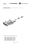
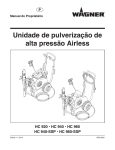
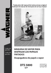
Operating manual Translation of the original operating instructions Continuous mixer 1 Aut om 0 .A us 2 Han d T 25 K Edition 05/2010 0343 856 GB Contents Page Safety regulations ................................................................... 2 Functional description ............................................................. 2 What materials can be used? .................................................. 3 Technical data ............................................................................... 3 Equipment overview .................................................................. 3 Putting device in operating position ................................... 4 Transport by crane ..................................................................... 4 Placing into operation ........................................................... 5 Breaks in work ............................................................................ 5 Winter operation ......................................................................... 5 Placing out of operation and cleaning device ........5/6 Placing the device in its transport position ...................7/8 Page Malfunction checklist .............................................................8 Servicing ................................................................................... 8/9 Sieve in pressure reducer ..................................................... 8/9 Tightening the special V-belt ..................................................9 Accessories ............................................................................. 9-11 Spare parts list - continuous mixer T 25 K ........................ 12 Spare parts illustration - continuous mixer T 25 K ......... 13 Spare parts list and illustration electric components .. 14 Spare parts list and illustration water fittings ................. 14 Important notes on product liability ........................... 15 Guarantee declaration ......................................................... 16 Declaration of conformity ................................................. 18 Wagner manufacturing and sales companies........... 20 Safety regulations 1. Read the operating manual carefully and follow the instructions given therein, in order to avoid possible danger. 2. The general safety and accident regulations for the building trade should be observed when using the continuous mixer T 25 K. 3. Never put your hands into the continuous Achtung mixer T 25 K when it is running. 4. The continuous mixer T 25 K should only be used with the coating materials listed on page 3. It is not permitted to use it for any other purpose. The manufacturer will not be liable for damages resulting from such improper use. The risks are the sole responsibility of the user. 5. Always keep the operating manual available where the continuous mixer T 25 K is used. 6. Check the continuous mixer T 25 K for visible damage each time before putting it into operation. In particular, the electrical lines, plug and couplings. 7. The protective devices, the protective grid on the container and the cover for the V-belt drive should be fastened properly. 8. To avoid occupational illnesses, observe the processing instructions from the manufacturer of the material used when preparing and using the materials and cleaning device. Protective clothing, gloves and, if necessary, skin cream are necessary to protect the skin. 9. Turn off the continuous mixer T 25 K before carrying out cleaning and maintenance work. Remove mains plug from the socket. 10. Cleaning the device Never spray with sharp jet, in particular with high-pressure or pressure steam cleaners. Danger of short circuit from water getting in. 11. Always remove the mains plug from the socket when carrying out any work on electrical components. 12. Have all work or repairs to the electrical equipment carried out by a specialist electrician, even if there are references to such in the operating manual. No liability will be accepted for improper installation. Functional description The technical construction will be briefly explained here in order to enable a better understanding of the operation of the device. The protective grid with sack opener on the container protects the transport shaft from lumps in the coating material used. The electric motor drives the transport and mixing shaft by means of a V-belt. The transport shaft moves the coating material to be mixed from the container to the dosing section and from there to mixing section. The water for the coating material flows from the water connection over a fixed adjustment pressure reducer to a solenoid valve. This opens when the device is switched on. The water flow is adjustable by means of the fine control valve. A water flow display is available as accessory. The water is added in the front region of the mixing pipe according to the proportions stipulated by the coating material manufacturer. A beating device on the mixing shaft means that the coating material is mixed into water. The coating material comes out at the end of the mixing pipe into a container or conveying device. T 25 K GB What materials can be used? Technical data Continuous mixer T 25 K The continuous mixer T 25 K has been designed for use with materials in sacks. It is suitable for universal mixing of the following coating materials which have been premixed by the manufacturer: •Mineral adhesives •Building adhesives •Mineral texture plaster up to grain size 5 mm •Lime cement plaster •Cement plaster •Indoor lime plaster •Renovating plaster •Fine concrete •Flow flooring plaster Equipment overview 1 2 3 4 5 6 2.2 kW Voltage: 230 V ~, 50 Hz Fuse protection: 16 A Mains cable: 3 x 1.5 mm², 3 m Mixing amounts: 20 l/min Noise level: 70 dB (A) Water connection: Claw coupling for DN 13mm (1/2 inch) water hose Water pressure from supply line: at least 3 bar Only use other coating materials in consultation with WAGNER Application Technology Department. Motor output P1: Container contents: 60 l Measurements L x W x H: Operating position: Transport position: 1630 x 750 x 1040 mm 1210 x 750 x 600 mm Weight: 105 kg Tire pressure, max.: 2 bar 7 Coating material output 8 Clamping lock for mixing pipe 9 Attachment for water flow display (accessory) 10 Water connection, external 11 Ball valves (2) for emtying water 12 Pressure reducer solenoid valve 13 Fine control valve 14 Overcurrent protection switch 15 ON/OFF motor protection switch 16 Changeover switch for system: attachable container (accessory) big bag / silo (accessory) 17 Mains cable 18 socket for sensor control system S 230 (accessory) Transport shaft Protective grid with sack opener Water connection for mixing pipe Swiveling device for mixing pipe Mixing pipe with mixing shaft Spring pin for fastening the mixing shaft 1 2 18 17 1 0 Au tom . Au s 16 15 2 Ha nd 3 14 13 4 5 12 11 10 9 8 7 T 25 K 6 3 GB Putting device in operating position Pull back latching bolts (1, fig. 2). Take up position (2) in front of the device. Hold device (3) with handle and pull slowly in the direction of the arrow. Caution: Remember the weight of the device. Achtung 4 Make sure that the latching bolts (4) engage in trolley frame (5). 5 1 5 3 4 Transport by crane Straps or ropes (not wire cables) should be used for transporting the device by crane. Minimum carrying power 250 kg. Only transport by crane with empty container. 2 Remove linch pin (1, fig. 3) for securing the mixing pipe. Take mixing pipe (2) and swivel forwards. 1 1 Aut om 0 . Aus 2 Han d 2 3 Pull mixing pipe forwards. Swivel mixing shaft (3, fig. 3) into the transport shaft. Push mixing pipe onto connection (4, fig. 4) on the device and secure with the two toggle-type fasteners (5). 4 T 25 K GB Placing into operation Breaks in work 1. Place device in operating position, see page 4. 2. Ensure that the mains voltage is in accordance with the details on the rating plate before connecting to the mains voltage. The device should be connected using a shockproof socket grounded according to regulations. 3. If an extension cable is required, use design 3x 2.5 mm². 4. Connect water hose (1, fig. 6) to device and mixing pipe. 5. Connect external water hose DN 13 mm (1/2 inch) with claw coupling to device (2). 6. Fill container with coating material. 7. Turn fine control valve (3) to the left (anti-clockwise). 8. Set system changeover switch (4) (accessory) to Manual 2. 9. Turn on device with motor protection switch (5). 10. Check that the coating material coming out of the mixing pipe has the correct consistency. 11. Adjust the water flow volume using the fine control valve (3) •Turntotheleft(anti-clockwise) – more water. •Turntotheright(clockwise) – less water. 12. Overload of the continuous mixer T 25 K. The electric motor switches off automatically and remains switched off. Operate the overcurrent protection switch (6), after about 2-3 minutes - the device will start up again. 1. Turn off devices. 2. Always observe the setting time of the coating material. The coating material may harden with longer breaks in work. Winter operation If there is danger of frost, completely empty the water fittings. 1. Disconnect the external water hose. 2. Open ball valves (1, fig. 7) to empty out the water. 3. Close ball valves (1) before starting up again. 1 1 0 Au tom . Au s 2 Ha nd Placing out of operation and cleaning the device 4 T 25 K 5 6 3 2 1 1. 2. 3. 4. 5. 6. 7. 8. 9. Turn off device. Remove the mains plug from the socket. Turn off water supply and uncouple external water hose. Uncouple water hose (1, fig. 8) from mixing pipe. Undo toggle-type fasteners (2) on mixing pipe. Put mixing pipe forwards. Pull out spring pin (3) from mixing shaft. Swivel out the mixing pipe sideways. Remove mixing shaft from the mixing pipe and clean both parts with water. 10. Replace mixing shaft in the mixing pipe and secure with spring pin (3). 5 GB 3 1 2 3 4 11. Turn mixing pipe (1, fig. 9) back onto the container as far as it will go. Secure mixing pipe with linch pin (2). 5 1 1 0 Au tom . Au s 2 Ha nd 2 1 12. Clean container. Pull back latching bolts (1, fig. 10). Take up position in front of the device (2). Hold device with handle (3) and turn in the direction of the arrow until safety hook (4) stops. Release safety hook (4). Slowly turn device in the direction of the arrow (180°) to empty completely. Caution: Remember the weight of the device. Achtung 6 2 Then turn the device back into its operating position. Take care that the latching bolts engage in the trolley frame. 13. If coating material still remains in the container: Unscrew hexagon nut (5, fig. 10) and remove protective grid. Dry container and dosing section and clean with a brush. Re-fit the protective grid. T 25 K GB Placing the device in its transport position 1. 2. 3. 4. Remove mains plug from the socket. Uncouple external water hose. Uncouple water hoses (1, fig. 11) from mixing pipe. Undo toggle-type fasteners (2). Pull mixing pipe forwards. 3 1 4 1 0 Au tom . Au s 2 Ha nd 1 2 5. Swivel mixing pipe (1, fig. 12) as far as it will go onto the container. Secure mixing pipe with linch pin (2). 2 1 2 7. Take care that the latching bolts (1, fig. 14) engage in the trolley frame (2). 6. Pull back latching bolts (1, fig. 13). Take up position (2) in front of the device. Hold device with handle (3) and turn in the direction of the arrow until safety hook (4) stops. Release safety hook (4). Slowly turn device in the direction of the arrow (180°). 1 2 Caution: Remember the weight of the device. Achtung T 25 K 7 GB 8. The device can be positioned vertically if there is little space available, see fig. 15. 9. The device should be secured properly with suitable means when transporting. Malfunction checklist Fault The device does not start up Possible cause •No mains voltage •Coating material hardened in the •Check mains connection, check fuse. •Clean mixing pipe. • •Solenoid valve does not open. •Water volume too low. •Water volume too great. •Sieve in pressure reducer dirty. • •Change. •Turn fine control valve to the left. •Turn fine control valve to the right. •Clean sieve. •V-belt tension too low •Tighten the V-belt, see fig. 17 page 9. mixing pipe causing the overcurrent protection switch to trigger. Start-up capacitor (2) defective. No water in mixing pipe Coating material too thick Coating material too thin Consistency of the coating material fluctuates The device does not mix, squeaking noises Remedy Operate overcurrent protection switch, the device will start up again. Have changed by a specialist electrician. Servicing Sieve in pressure reducer (1, fig. 16) From time to time check that the sieve is not dirty, if necessary clean. 1. 2. 3. 4. 5. 6. 8 Remove mains plug from the socket. Uncouple the external water hose. Open ball valves (2) for emptying water. Remove sealing cap (3) with open-end wrench 30. Remove sieve (4) Rinse sieve with water. Blow through with compressed air, if available. T 25 K GB Accessories 1 Water flow display Enables: The water volume to be controlled for a certain coating material according to the manufacturer's specifications. The readjustment of the water volume for a particular coating material. Part No. 0343 700 3 4 2 Tightening the special V-belt (fig. 17) 1. Remove mains plug from the socket. 2. Unscrew the 3 hexagon nuts (1, fig. 17) with open-end wrench 13. 3. Remove cover (2). 4. Loosen the 4 hexagon bolts (3) with open-end wrench 13. 5. Set depth of impression on the idle belt section to 1-2 mm with tension screw (4). Turn V-belt pulley several times and check depth of impression. 6. Re-tighten the hexagon bolts (3). 7. Fit the cover. Achtung Attention For replacement of the V-belt, use only the special Wagner V-belt. 1 Cover Serves as protection against humidity, dirt and as protection against the wind. Part No. 0343 701 2 1-2 mm 3 1 0 Au tom . Au s 2 Ha nd 4 T 25 K 9 GB Accessories Vibrator Set Reduces bridging of the coating material in the container to a minimum. Part No. 0343 709 Universally applicable material machine communication. System attachable container For use with materials in sacks. •Attachable container for continuous mixer T 25 K •Sensor control system S 230 •Wet and dry sensor •Mounting for wet sensor •Water pressure controller 1 Aut om 0 . Aus 2 Han d Part No. 0343 908 S2 30 10 T 25 K GB Accessories System - big bag / silo For use with coating materials from a big bag / silo. Silo delivery hood Sensor control system S 230 Wet and dry sensor Water pressure controller • • • • Part No. 0343 909 1 Aut om 0 . Aus 2 Han d S2 30 T 25 K 11 12 Protective grid 0343 202 9910 208 0343 385 9922 603 9922 506 3053 889 0343 326 0343 310 0343 303 9921 502 9900 111 0343 301 9900 202 9910 204 0343 204 9995 309 9903 322 0343 205 9900 129 1 2 4 5 6 7 8 9 10 11 12 15 16 17 18 19 20 22 23 Hexagon bolt M5 x 10 DIN 933 (2) Mixing shaft Bolt M4 x 10 Linch pin Conveying shaft Hexagon nut M6 DIN 985 Hexagon bolt M6 x 40 DIN 931 Driving shaft Hexagon bolt M6 x 16 DIN 933 (3) Split washer A6 DIN 127 (3) Sealing flange Seal Distance bush Deep groove ball bearing 6205 RS (2) Locking ring 25 x 1.2 DIN 471 Locking ring 52 x 2 DIN 472 V-Belt XPZ 1120 Ld Aramid Hexagon nut M8 DIN 985 Description Item Part No. Spare parts list - continuous mixer T 25 K 0343 330 3061 423 9930 301 9994 950 0343 386 0343 387 0343 388 9921 501 9900 109 0343 233 31 32 33 34 35 36 37 38 39 9953 149 9953 150 0343 715 0343 302 0343 325 0343 314 30 29 28 27 26 25 24 Item Part No. V-belt tensioning device Hexagon bolt M8 x 25 DIN 933 Split washer A8 DIN 127 Connecting bar Bracket Tension screw Wheel cap (2) Split-pin (2) Washer B 21 DIN 125 (2) Wheel (2) Capacitor 40 MF/400 V, 230 V~, 50 Hz Operating capacitor Capacitor (2 pieces) 80 MF/320 V, 230 V~, 50 Hz Start-up capacitor Mixing pipe (pos. 20, 23, 24, 25, 26) Plain bearing Knotted-link chain Spring pin Description GB T 25 K T 25 K 33 31 35 38 32 34 39 30 37 36 4 5 6 7 8 7 9 11 12 28/29 10 1 22 2 27 17 15 16 23 18 24 25 26 20 19 20 GB Spare parts illustration - continuous mixer T 25 K 13 GB Spare parts list - electric components Item Part No. Description 1 0343 216 ON/OFF motor protection switch 230 V~, 50 Hz 2 0343 363 Overcurrent protection switch 3 9951 075 Hexagon nut 4 9951 074 Screwed cable gland 5 0343 213 Mains cable 3 x 1.5 mm², 3 m 1 Au to 5 m. 0 Au s 2 Ha nd 4 3 1 2 Spare parts list - water fittings Item Part No. Description Item Part No. Description 1 0268 579 Sealing cap 3 0343 211 Water hose, 380 mm long 2 0268 578 Sieve 4 0343 319 Solenoid valve 4 1 2 3 14 T 25 K GB Important notes on product liability As a result of an EC regulation being effective from January 1, 1990, the manufacturer shall only be liable for his product if all parts come from him or are released by him, and if devices are properly mounted and operated. If the user applies outside accessories and spare parts , the manufacturer's liability can fully or partially be inapplicable; in extreme cases usage of the entire device can be prohibited by the competent authorities (employer's liability insurance association and factory inspectorate division). Only the usage of original WAGNER accessories and spare parts guarantees that all safety regulations are observed. NOTE ON DISPOSAL In observance of the European Directive 2002/96/EC on waste electrical and electronic equipment and implementation in accordance with national law, this product is not to be disposed of together with household waste material but must be recycled in an environmentally friendly way! Wagner or one of our dealers will take back your used Wagner waste electrical or electronic equipment and will dispose of it for you in an environmentally friendly way. Please ask your local Wagner service centre or dealer for details or contact us direct. T 25 K 15 GB GUARANTEE DECLARATION (Status 01.02.2009) 1. Scope of guarantee 3. Handling All Wagner professional colour application devices (hereafter referred to as products) are carefully inspected, tested and are subject to strict checks under Wagner quality assurance. Wagner exclusively issues extended guarantees to commercial or professional users (hereafter referred to as “customer”) who have purchased the product in an authorised specialist shop, and which relate to the products listed for that customer on the Internet under www.wagner-group.com/profi-guarantee. The buyer’s claim for liability for defects from the purchase agreement with the seller as well as statutory rights are not impaired by this guarantee. We provide a guarantee in that we decide whether to replace or repair the product or individual parts, or take the device back and reimburse the purchase price. The costs for materials and working hours are our responsibility. Replaced products or parts become our property. If defects can be seen in the materials, processing or performance of the device during the guarantee period, guarantee claims must be made immediately, or at the latest within a period of 2 weeks. The authorised specialist shop that delivered the device is entitled to accept guarantee claims. Guarantee claims may also be made to the service centres named in our operating instructions. The product has to be sent without charge or presented together with the original purchase document that includes details of the purchase date and the name of the product. In order to claim for an extension to the guarantee, the guarantee certificate must be included. The costs as well as the risk of loss or damage to the product in transit or by the centre that accepts the guarantee claims or who delivers the repaired product, are the responsibility of the customer. 2. Guarantee period and registration The guarantee period amounts to 36 months. For industrial use or equal wear, such as shift operations in particular, or in the event of rentals it amounts to 12 months. Systems driven by petrol or air are also guaranteed for a 12 month period. The guarantee period begins with the day of delivery by the authorised specialist shop. The date on the original purchase document is authoritative. For all products bought in authorised specialist shops from 01.02.2009 the guarantee period is extended to 24 months providing the buyer of these devices registers in accordance with the following conditions within 4 weeks of the day of delivery by the authorised specialist shop. Registration can be completed on the Internet under www.wagner-group.com/profi-guarantee. The guarantee certificate is valid as confirmation, as is the original purchase document that carries the date of the purchase. Registration is only possible if the buyer is in agreement with having the data being stored that is entered during registration. When services are carried out under guarantee the guarantee period for the product is neither extended nor renewed. Once the guarantee period has expired, claims made against the guarantee or from the guarantee can no longer be enforced. 4. Exclusion of guarantee Guarantee claims cannot be considered - for parts that are subject to wear and tear due to use or other - - 16 natural wear and tear, as well as defects in the product that are a result of natural wear and tear, or wear and tear due to use. This includes in particular cables, valves, packaging, jets, cylinders, pistons, means-carrying housing components, filters, pipes, seals, rotors, stators, etc. Damage due to wear and tear that is caused in particular by sanded coating materials, such as dispersions, plaster, putty, adhesives, glazes, quartz foundation. in the event of errors in devices that are due to non-compliance with the operating instructions, unsuitable or unprofessional use, incorrect assembly and/or commissioning by the buyer or by a third party, or utilisation other than is intended, abnormal ambient conditions, unsuitable coating materials, unsuitable operating conditions, operation with the incorrect mains voltage supply/frequency, over-operation or defective servicing or care and/or cleaning. for errors in the device that have been caused by using accessory parts, additional components or spare parts that are not original Wagner parts. for products to which modifications or additions have been carried out. for products where the serial number has been removed or is illegible for products to which attempts at repairs have been carried out by unauthorised persons. for products with slight deviations from the target properties, which are negligible with regard to the value and usability of the device. for products that have been partially or fully taken apart. T 25 K GB 5. Additional regulations. The above guarantees apply exclusively to products that have been bought by authorised specialist shops in the EU, CIS, Australia and are used within the reference country. If the check shows that the case is not a guarantee case, repairs are carried out at the expense of the buyer. The above regulations manage the legal relationship to us concludingly. Additional claims, in particular for damages and losses of any type, which occur as a result of the product or its use, are excluded from the product liability act except with regard to the area of application. Claims for liability for defects to the specialist trader remain unaffected. German law applies to this guarantee. The contractual language is German. In the event that the meaning of the German and a foreign text of this guarantee deviate from one another, the meaning of the German text has priority. J. Wagner GmbH Division Professional Finishing Otto Lilienthal Strasse 18 88677 Markdorf Federal Republic of Germany Subject to modifications ∙ Printed in Germany T 25 K 17 GB 18 T 25 K GB T 25 K 19 GB A J. Wagner Ges.m.b.H. Ottogasse 2/20 2333 Leopoldsdorf Österreich Tel. +43/ 2235 / 44 158 Telefax +43/ 2235 / 44 163 [email protected] DK Wagner Spraytech Scandinavia A/S Helgeshøj Allé 28 2630 Taastrup Denmark Tel. +45/43/ 27 18 18 Telefax +45/43/ 43 05 28 [email protected] GB B Wagner Spraytech Benelux b.v. Veilinglaan 56 1861 Meise-Wolvertem Belgium Tel. +32/2/269 46 75 Telefax +32/2/269 78 45 [email protected] E Wagner Spraytech Iberica S.A. P.O. Box 132, Crta. N-340 08750 Molins de Rey Barcelona / Espania Tel. +34/93/6800028 Telefax +34/93/66800555 [email protected] I Wagner Colora Via Fermi, 3 20040 Burago di Molgora (MI) Italia Tel. +39/ 039 / 625 021 Telefax +39/ 039 / 685 18 00 [email protected] CH Wagner International AG Industriestrasse 22 9450 Altstätten Schweiz Tel. +41/71 / 7 57 22 11 Telefax +41/71 / 7 57 22 22 [email protected] F J. Wagner France S.a.r.l. Parc de Gutenberg - Bâtiment F 8 voie la Cardon, 91127 Palaiseau Cedex France Tel. +33/1/825 011 111 Telefax +33/1/698 172 57 [email protected] NL Wagner Spraytech Benelux b.v. Zonneban 10, 3542 EC Utrecht Netherlands Tel. +31/ 30/241 41 55 Telefax +31/ 30/241 17 87 [email protected] D J. Wagner GmbH Otto-Lilienthal-Straße 18 D-88677 Markdorf Postfach 11 20 D-88669 Markdorf Deutschland Tel.: +49 / 75 44 / 505 - 664 Fax: +49 / 75 44 / 505 -155 [email protected] www.wagner-group.com CZ Wagner, spol. s r.o. Nedasovská str. 345 155 21 Praha 5 -Zlicín Czechia Tel. +42/ 2 / 579 50 412 Telefax +42/ 2 / 579 51 052 [email protected] S Wagner Spraytech Scandinavia A/S Helgeshøj Allé 28 2630 Taastrup Denmark Tel. +45/43/ 21 18 18 Telefax +45/43/ 43 05 28 [email protected] Wagner Spraytech (UK) Limited The Coach House 2 Main Road Middleton Cheney OX17 2ND Great Britain UK-Helpline 0844 335 0517 5 p per minute (landline) www.wagner-group.com 20 T 25 K