1
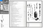
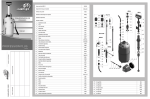
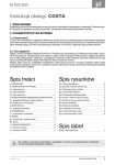
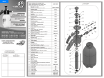
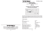
Menu
OPRYSKIWACZ
PLECAKOWY
PRESSURISED
KNAPSACK
HAND SPRAYER
РАНЦЕВЫЙ
ПОМПОВЫЙ
ОПРЫСКИВАТЕЛЬ
ОПРЫСКИВАТЕЛЬ
INSTRUKCJA OBSŁUGI
OWNER MANUAL
ИНСТРУКЦИЯ ПО ЭКСПЛУАТАЦИИ
TITAN 12, 16, 20
data naprawy
date of the repair
дата ремонта
ГАРАНТИЙНЫЙ ТАЛОН
KARTA GWARANCYJNA
GUARANTEE CARD
opis wady
description of the fault
описание дефектов
pieczęć sprzedawcy i data
stamp of the retailer and the date
дата и печать продавца
041/PL,GB,RUS/2010/A
Lanca teleskopowa z rączką
Telescopic lance with handle / Телескоп. штанга с рукояткой
R010mx (s)
Lanca teleskopowa bez rączki
Telescopic lance without handle / Телескоп. штанга без рукоятки
R01mx (s)
Zestaw końcówka lancy z MR1,5
Lance tip with nozzle MR1.5 / Наконечник для штанги с MR1,5
Z12/15 (V)
Nakrętka pompy uzbrojona
Pump nut with seal / Гайка насоса армированная
ZT11aU
Pompa kompletna
Complete pump / Комплектный насос
T5C (V)
Zawór bezpieczeństwa
Safety valve / Предохранительный клапан
R03dt
Rączka lancy zintegrowana z zaworem dozującym kpl.
Feeding valve integrated with handle / Компл. рукоятка штанги интегрированная с дозирующим клапаном
R020j (V)
RP10 (B) (C)
1
Zbiornik Titan / Container Titan / Бачок Titan
2
Podstawa zbiornika / Container base / Основа бачка
RP24
3
Nakrętka podstawy / Container base’s cap / Гайка основы
RP41
4
Lejek z filtrem / Funnel with sieje / Воронка с фильтром
RP22
5
Nakrętka zbiornika / Container cap / Крышка бачка
RP11
6
Nakrętka pompy / Pump nut / Крышка насоса
RP11a
ZT4
7
Pompa produkcyjna / Pump / Производственный насос
8
Mieszacz / Mixer / Смеситель
RP17
9
Nakrętka kulki / Ball cap / Гайка шарикового клапана
RP18
10
Kosz pompy – połówka / Pump basket (half) / Стеллаж насоса
RP12
11
Nakrętka filtra / Filter nut / Гайка фильтра
RP20
12
Kulka szklana / Glass ball / Стеклянный шариковый клапан
M75g
13
Uchwyt paska / Carry belt’s handle / Крепление ремня
RP19
14
Cięgno dźwigni / Lever tie / Тяж рычага
M201
15
Wałek dźwigni / Lever bolster / Стержень рычага
M204
16
Dźwignia stalowa obtryśnięta / Steel lever / Рычаг
RP16
RP21
17
Zaślepka / Plug / Заглушка
18
Lanca obtrysk., fi 12 mm / Lance pipe., fi 12 mm / Штанга, fi 12 мм
R73nx50
19
Lanca obtrysk., fi 8 mm / Lance pipe., fi 8 mm / Штанга, fi 8 мм
R73mx60
20
Tulejka zaciskowa, fi 8 mm / Clasp faucet, fi 8 mm / Зажимная втулка, fi 8 мм
R103
21
Przycisk zaworu dozującego / Feeding valve trigger / Кнопка дозирующего клапана
R44
22
Rączka lancy zintegrowana z zaworem dozującym
Feeding valve integrated with handle / Рукоятка штанги интегрированная с дозирующим клапаном
R02j
23
Filterek / Filter / Фильтр
R40
24
Końcówka węża, sztucerek / Hose end piston / Патрубок шланга
R81f
25
Nakrętka węża / Hose nut / Гайка шланга
R80f
26
Wąż / Hose / Шланг
27
Sprężyna wzmacniająca do węża / Hose spring / Пружина укрепляющая шланг
28
Rurka zasysająca / Sucking pipe / Трубка засасывающая жидкость
29
Rdzeń dyszy / Nozzle nucleus / Стержень форсунки
T26C (V)
R13t
M08_12
R114
R64
30
Nakrętka dyszy / Nozzle nut / Гайка форсунки
31
Nakrętka dyszy 1.5 do MR / Nozzle 1.5 nut for MR / Гайка форсунки 1.5 для MR
R115_1.5
32
Tłoczek z oringami / Piston with o-rings / Втулка с прокладками
R43a (V)
33
Sprężynka / Spring / Пружинка
R48a
34
Nakrętka bez otworu / Nut without hole / Гайка без отверстия
R50
35
Nakrętka M-16 / Nut M-16 / Гайка M-16
R26
36
Sprężynka / Spring / Пружинка
R13n
45
O-ring 100x3
R112
37
Zawór bezp. – uchwyt / Safety valve – handle / Втулка предохр. клапана
R100
46
O-ring 50x5
R105
38
Uszczelka pompy (wargowa ) / Pump seal / Прокладка насоса
M81
47
O-ring 35x5
R104 (V)
39
Uszczelka wieczka / Container’s cap seal / Прокладка крышки
M80
48
O-ring11,3x2,4
R47c (V)
40
Pierścień zaciskowy / Clasp ring / Зажимное кольцо
R106
49
O-ring 10x2
R41
41
Tulejka teleskopu / Telescope ring faucet / Втулка телескоп. штанги
R109
50
O-ring 8x2
R108 (V)
42
Pierścień zapinka lancy / Lance ring clasp / Цепной замок штанги
R107
51
O-ring 5,3x2
R116 (V)
43
Podkładka / Pad / Подкладка
52
O-ring 3x2
R42 (V)
44
Zawleczka / Cotter / Шплинт
53
Pręt mosiężny, fi 3 mm / Brass bar, fi 3 mm / Латунный прут, fi 3 мм
M11
USER’S MANUAL
KNAPSACK SPRAYER
TITAN 12, 16, 20
Knapsack sprayer is intended for pest control treatments and spraying with fertilizers
in hotbeds, greenhouses, on vegetable and flower plantations and on small fields.
1. TECHNICAL DATA
Titan 12
Titan 16
Titan 20
Model
Total capacity
14.00 l
18.30 l
22.00 l
Working capacity
12.00 l
16.00 l
20.00 l
Average liquid output
0.5 - 1.0 litr/min
Max working pressure
0.3 MPa (3 bar)
Nett weight
4,00 kg
4,00 kg
4,20 kg
Dimensions
160 mm x 390 mm 180 mm x 410 mm 205 mm x 410 mm
x 610 mm
x 610 mm
x 610 mm
2. KNAPSACK TITAN ELEMENTS
In each packing of the knapsack Titan the following elements can be found:
1. Complete container with a pump and a lever.
2. Hose with nuts, a sucking pipe and a feeding valve integrated with lance handle.
3. Telescopic lance with regulated nozzle MR 1,5 mm
4. A packet of additional spare parts, seals and silicone smear
5. User’s manual with a guarantee card.
We also offer a version of the knapsack with Viton seals and the telescopic lance made
from the stainless steel.
Company Marolex Sp. z o. o. reserves a right to make changes in the enclosed with the
sprayer parts.
3. CONSTRUCTION AND OPERATION
The container is made from plastic. In its upper part there is a screwed inlet covered by a
lid. In the inlet there is a sieve. In the bottom of the container there is installed a pivot of
the pump lever. The lever is connected by a wire with the pump piston. To assemble the
sprayers put the sucking pipe inside the pump and screw the hose on to the pump. On the
other end of the hose screw on the lance to the handle.
After filling the container with liquid through a sieve and taking it on the back, the lance
should be taken in the right hand, and the handle of the pump lever in the left hand. When
moving the lever up and down the pump piston moves in sliding motion. When it moves
up it sucks the liquid to the pump cylinder and when it moves down it pushes the liquid
into the pressure header creating pressure in the pump.
4. MAINTENANCE RECOMMENDATIONS
1. It is not recommended to fill in the container over the working capacity.
2. The sprayer should be stored in a shaded place, in temperature above +4 degrees.
3. During work with Titan you must comply with safety and hygiene regulations and
strictly follow instructions given on the package of applied chemicals.
4. After finishing work, the sprayer must be emptied and thoroughly rinsed with water.
The filter inside the handle must be taken out and cleaned. When the sprayer is
completely assembled, pump it up and blow the air through it.
5. The remains of the liquid left in the lance for winter may in the minus temperatures
freeze, expand and damage the valve or handle.
Sprayer once used for spraying pesticides
can not be used for any other purposes!
Caution!
When the pump lever gets blocked during the work, it means that the maximum pressure
was reached and further pumping will result in opening the safety valve. If the nozzle does
not work well in spite of the maximum pressure in the pump it can be caused by leaks
through non-hermetic elements. In such case the hose nuts R80f at the pump and the
handle should be checked if they are screwed on properly and there are no leaks.
If the problem with the nozzle still exists, the sucking pipe should be checked as it could fall
out from the hose fitting R81f. To install the sucking pipe the following operations should be
taken:
- empty the sprayer from any remaining liquid;
- release the pressure from the pump by pulling the safety valve out;
- unscrew the hose nut R80f at the pump;
- turn the container upside down so the sucking pipe will fall out from the container.
Caution: be careful as the remains of the working liquid will flow out as well;
- put the sucking pipe in the hose fitting R81f then push the hose fitting into the hose, put
the hose nut R80f on it and screw on to the pump.
8. GUARANTEE CONDITIONS AND REPAIRS
6. TECHNICAL INSTRUCTIONS
1.
2.
3.
4.
Schema – fastening of the belts and the clasp
adjustable clasp
belt release
7.
8.
9.
The guarantee period is 24 months from the date of purchase.
Sprayers with chemical remains will not be repaired.
Reclamation should be lodged to the seller of the sprayer.
The claims will be accepted after showing the defected part or giving the full description
of the fault.
Number of repairs after which the seller can’t refuse to exchange the sprayer for a new
one (in case there are still defects) is 3.
Operations connected with exploitation of the sprayer and described in the manual are
not treated as guarantee repairs.
The producer won’t accept the claim if there were changes in pressure regulation or
the storing, operating, maintaining of the product were not according to the manual.
Mechanical damages caused by the user can’t be the subject to reclamation. The
damaged parts can be exchanged but the costs are charged.
The guarantee repairs should be made using always the genuine Marolex parts.
9. MAINTENANCE AND SERVICE RECOMMENDATIONS
5. WORK SAFETY RECOMMENDATIONS
1. Children, pregnant women, people taking medicines or other drugs restricting the
concentration powers or drinking alcohol are forbidden to operate the sprayer.
2. For initial operation use clean water to test the sprayer first..
3. When working with chemicals (also during liquid preparation and destroying the
packages) it is necessary to wear protective clothing (rubber boots, gloves, a coat, a
cap and a mask).
4. It’s forbidden to work with chemicals on an empty stomach and eat or drink during
working. It’s forbidden to drink alcohol one day before and one day after working with
chemicals.
5. It’s forbidden to pour the liquid remains to the open water reservoirs or biological
sewage treatment plants. These notes apply also to the water after cleansing the
container and other parts of the sprayer.
6. Expendable sprayer should be handed over for utilization.
7. In case of poisoning immediately contact the doctor.
8. People working using the sprayer should strictly comply to all the recommendations on
the package of the spraying agents.
9. It’s forbidden to work using leaky or disabled sprayer.
10. All the operations should be done after decompression of the sprayer.
11. Thoroughly wash the sprayer after each usage and especially before making its
servicing.
12. It’s forbidden to use the sprayer for other purposes than stipulated in the user’s
manual.
13. Store the sprayer clean and empty and especially during winter make sure that there
are no liquid remains in the container or the lance.
14. The only device for making the working pressure is a pump placed inside the
container – it’s forbidden to use any other devices for this purpose !!!
15. It’s forbidden to spray with easy inflammable chemicals or substances
which can cause an explosion eg. Petrol, solvents.
16. Changes in the sprayer or using it not according to its allocation can result
in poisoning people or animals, polluting the environment, damaging the sprayer or
accidents.
17. After finishing work, you should change your clothes (the protective clothes must be
cleaned), wash your hands, face, mouth and throat, and clean your nose.
18. After finishing work, the remaining liquid should be diluted ten times using clean water
and sprayed on the same area as before.
19. After finishing work, the sprayer must be emptied and thoroughly rinsed with water.
Then it should be pumped empty and then the air blown through it after opening the
valve R020j.
20. The user is fully responsible for the damages caused by not complying with these
recommendations.
21. The sprayer must be stored empty and non–pressurized.
22. The sprayer should be stored in safe places, secured from unauthorized people,
especially children.
5.
6.
After finishing work, and cleaning the sprayer the following operations should be taken to
ensure the longlasting operation:
1. Unscrew the hose from the handle, take out the filter R40, clean it at the running water
and put back again.
2. Unscrew the nut R50 from the integrated handle, take out the feeding valve’s piston
with the spring, clean it, lubricate with the silicone smear and install it back.
3. Unscrew the nozzle nut R64, take out the nozzle, wash it and put back.
4. It is recommended to lubricate the seal of the pump piston R104. To do it, take out the
pin (on the draft no.44), pull out the pump lever wire M201 from the pump, unscrew
the pump nut RP11a, take out the pump, dismantle the mixer RP17, take out the
pump from the pump basket and lubricate the seal. Assemble everything back again.
hip belt lock
adjustable clasp
belt release
tightening the belt
GB
10. DISMANTLING AND UTILISATION
The damaged sprayer, not suitable for repair, should be utilised in such way as not to
pollute the environment.
Cleansed plastic elements should be recycled as well as the metal parts.
NOZZLES. Liquid output at 0.35 Mpa
nozzle
colour
MR1.0
MR1.5
MR2.0
MF2.110
MF3.110
MF4.110
MF4.45
MF5.30
green
green yellow
red
yellow
blue
red
red
gold-brown
liquid
output
~0,40 litre/min.
~0,60 litre/min.
~0,80 litre/min.
nozzle type
3 nozzle 5 nozzle 7 nozzle
kit
kit
kit
Z09j3
Z09j7
Z09j5
adjustable stream
angle
~0,80 litre/min.
~1,15 litre/min. flatstream
~1,65 litre/min.
~1,10 litre/min. flatstream with
~1,60 litre/min. metal insert
The marked nozzles: MR1.0, MR1.5 are included with the sprayer Titan. The other nozzles can be
purchased in kits at our distributors or in our e-shop: http://sklep.marolex.pl
11. SAFETY SIGNS
lp.
meaning
sign
place
1.
tablet
on container
2.
Sign indicating possibility of unspecified danger.
on container
3.
Sign indicating that a users manual should be read
before starting work.
on container
4.
Sign indicating danger of poisoning. Eating or
drinking while using the device is forbiden.
on container
7. ADAPTING THE KNAPSACK FOR THE LEFTHANDED USER
Manufacturer:
The sprayer in the version you bought is suitable for the righthanded user. However, the
manufacturer designed the sprayer is such a way as to make it possible to adapt the device for
the lefthanded user. It can be done by the user himself and these are the steps to follow:
- unpin the cotters (no. 44);
- draw the whole lever set (tie M201, lever RP16, roller M204) out of the container and
pump base;
- unscrew two top nuts: container nut no. RP11 (with the sieve) and pump nut no. RP11a
(with the whole pump set) and exchange their places;
- fix the lever set on the opposite side of the container and fasten it with the cotters.
Distributor: