1
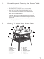
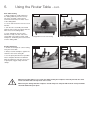
RPMSR
Professional
Router Table
Instruction
Manual
IMPORTANT
For your safety read
instructions carefully
before assembling or
using this product.
Save this manual for
future reference.
VERSION 2.0
Contents
Terms & Conditions Of Usage
Health & Safety Guidance
page 4
Record Power Guarantee
page 6
EU Declaration Of Conformity
page 18
User Manual
1.
Unpacking and cleaning the Router Table
2.
Getting To Know Your Router Table
page7
3.
Contents of loose parts bag
page 8
4.
Machine Specification
page 8
5.
Router Table Assembly
page 9
6.
Using the Router Table
page 12
7. Parts List
page 14
Essential Accessories
Quick Find
Part Description
Part Number
Collect Extension - 1/2"
RPMS-CX
page 7
3
Health & Safety Guidance
READ ALL THE INSTRUCTIONS IN THIS MANUAL
CAREFULLY BEFORE ASSEMBLY, INSTALLATION AND USE
OF THIS PRODUCT.
KEEP THESE INSTRUCTIONS IN A SAFE PLACE FOR
FUTURE REFERENCE.
WARNING: When using electric tools, basic safety precautions
should always be followed to reduce the risk of fire, electric
shock and personal injury.
Safe Operation
1. Eye Protection
The operation of any power tool can result in
foreign objects being thrown into your eyes, which can result
in severe eye damage. Always wear safety glasses or other
suitable eye protection. Wear safety glasses at all times.
Everyday glasses only have impact resistant lenses. They are
not safety glasses which give additional lateral protection. It is
also important to wear ear protectors when operating the table
saw.
2. Keep work area clear.
Cluttered areas and benches invite accidents and injuries.
3. Consider work area environment.
Do not expose the machine to rain or damp conditions.
• Keep the work area well lit.
• Do not use the machine in the presence of flammable
liquids or gases.
4. Guard against electric shock.
Avoid body contact with earthed or grounded surfaces.
5. Keep other persons away (and pets).
Do not let persons, especially children, not involved in the work,
touch the machine, or extension cord (if used) and keep visitors
away from the work area.
6. Store idle tools.
When not in use, tools should be stored in a dry, locked- up
place, out of reach of children.
7. Do not force the machine.
It will do the job better and work more safely if operated at the
speed at which it was intended.
8. Use the right tool.
• Do not force small tools to do the job of a heavy-duty tool.
• Do not use tools for purposes other than those for which they
were intended.
9. Dress properly.
• Non-slip footwear is recommended.
• Do not wear loose clothing, neckties or jewellery; they can be
caught in moving parts.
• Roll up long sleeves above the elbow.
• Wear protective hair covering to contain long hair.
10. Use protective equipment
• Use safety glasses. (See note 1. above)
• Use face or dust shield if cutting operation creates dust.
• Use ear plugs or ear defenders when the machine is in use
11. Connect dust extraction equipment.
(See section 9, page 22)
12. Do not abuse the cord.
Never yank the cord to disconnect it from the socket. Keep the
cord away from heat, oil and sharp edges.
13. Do not overreach.
Keep proper footing and balance at all times.
Record Power Health & Safety Guidance v1.0
14. Secure work.
Ensure that your work piece is properly held before
starting to cut.
15. Maintain tools with care.
• Follow instructions for lubrication and changing accessories.
• Inspect electric cords periodically and, if damaged, have them
repaired by an authorized service facility or qualified electrician.
• Inspect extension cords (if used) periodically and replace if
damaged. Always use properly rated extension cord.
16. Disconnect Machine.
When not in use, before servicing, changing blades etc.
disconnect the machine from the power supply.
17. Never leave machine running unattended.
Turn power off, do not leave machine until it comes to a
complete stop.
18. Remove adjusting keys and wrenches.
ENSURE that all adjusting wrenches and keys are removed
before switching the machine ‘ON’.
19. Avoid unintentional starting.
Ensure the switch is in the “STOP” position before turning on
the power from the main electricity supply. Your Record Table
saw already incorporates low voltage protection. This means
the machine will not automatically start up after say a power
cut, unless you first reset the start switch.
20. Out-door Extension Leads.
Your machine should not be used outdoors.
21. Stay alert.
Watch what you are doing, use common sense and do not use
the machine when you are tired.
22. Check for damaged parts.
• Before use of the machine, it should be carefully checked to
determine that it will operate properly and perform its intended
function.
• Check for alignment of moving parts, binding of moving parts,
breakage of parts, mounting and any other conditions that may
affect its operation.
• A guard or other part that is damaged should be properly
repaired or replaced by a qualified person unless otherwise
indicated in this instruction manual. Have defective switches
replaced by a qualified person.
• Do not use the machine if the switch does not turn on and off.
23. Warning!
• The use of any accessory or attachment, other than those
recommended in this instruction manual, or recommended by
our Company may present a risk of personal injury.
24. Have your machine repaired by a qualified person.
• This electric machine complies with the relevant safety rules.
Only qualified persons using original spare parts should carry
out repairs. Failure to do this may result in considerable danger
to the user.
25. This machine is designed for cutting wood.
• Do not use for cutting any material other than wood.
Maintenance and Servicing
This machine requires very little maintenance. This handbook
gives clear instructions on installation, set up and operation.
Read these instructions carefully. Remember always to switch
off and unplug from the main electricity supply before carrying
out any setting up or maintenance operations.
Should you need advice on the repair or maintenance of this
product, our Customer Service Department can be contacted
on 0870 770 1777 and will be happy to assist you.
Additional Safety Instructions
For Table Saws
SAFETY IS A COMBINATION OF OPERATOR
COMMON SENSE AND ALERTNESS AT ALL
TIMES WHEN THE TABLE SAW IS BEING
USED.
WARNING: FOR YOUR OWN SAFETY, DO NOT ATTEMPT
TO OPERATE YOUR TABLE SAW UNTIL IT IS COMPLETELY
ASSEMBLED AND INSTALLED ACCORDING TO THE
INSTRUCTIONS.
SAFE OPERATION
1. The table saw should be bolted to the floor where possible.
2. If you are not thoroughly familiar with the operation of
table saws, obtain advice from your supervisor, instructor, or
other qualified person or contact your retailer for information
on training courses. Do not use this machine until adequate
training has been undertaken.
3. Never turn the machine ‘ON’ before clearing the table of all
objects (tools, scrap pieces etc.)
4. Ensure that:
(i) the voltage of the machine corresponds to the mains voltage.
(ii) To use an earthed power source (wall socket).
(iii) The cord and plug are in good condition, i.e. not frayed or
damaged.
(iv) No saw teeth are missing and the blade is not cracked or
split. Otherwise replace blade.
(v) The blade is aligned.
5. Never start the machine with the saw blade pressed against
the workpiece.
11. If the electrics are damaged, parts must only be replaced by
a qualified electrician.
12. Never use a long extension cable.
13. Always use a push stick and keep hands clear of the blade.
14. Never remove the crown guard or riving knife. These are
there to protect the user.
15. WARNING LABELS – It is important that labels bearing
Health & Safety Warnings are not removed or painted over. New
labels are available from Customer Services.
16. MECHANICAL SAFETY – The security of all clamps and
work holding devices should be checked before switching on.
17. WOOD DUST – The fine particles of dust produced in
cutting operations are a potential health risk. Some imported
hardwoods do give off highly irritant dust which causes a
burning sensation. We strongly recommend the use of a
dust collector and dust mask/visor. Our Customer Services
Department will also be happy to advise you on the correct unit
for your needs.
18. This machine falls under the scope of the ‘Health &
Safety at Work etc. Act 1974’, and the ‘Provision & Use of
Work Equipment Regulations 1998’. We recommend that you
study and follow these regulations. For further help on any
of the above matters please contact our Customer Services
Department at :Tel: 0870 770 1777 Fax: 0870 770 1888
WARNING: Do not allow familiarity (gained from frequent use of
your machine) to cause complacency. Always remember that a
careless fraction of a second is sufficient to inflict severe injury.
6. Never apply sideways pressure on the blade.
7. Care must be taken when cutting wood with knots, nails or
cracks in it and / or dirt on it.
8. Never leave the machine running unattended.
9. Do not use saw blades which are damaged or deformed.
10. Ensure the selection of the saw blade is suitable for the
material to be cut.
4
5
Record Power Guarantee
1. INTRODUCTION
1.1 We supply machinery through a network of dealers and
authorised distributors and you should be aware that your
contract of sale is with the retailer from whom you purchased
this product. 1.2 If you are not satisfied with this product you should in the
first instance approach the retailer from whom you purchased it.
1.3 Customers have statutory rights to protect them and
information on this can be found at the Citizens Advice Bureau
or on such web-sites as that operated by the DTI (http://www.
dti.gov.uk)
1.4 Returning your guarantee card will speed up the claims
procedure and can be very helpful as a proof of purchase
should the initial receipt be mislaid or damaged. We recommend
that this is returned as close to your original purchase date as
possible.
1.5 Correct installation, set-up, adjustment and routine
maintenance of the machine are the responsibility of the enduser and problems arising from incorrect set-up, adjustment or
maintenance are not covered by the terms of this guarantee.
However support is available in the first instance from the retailer
who supplied you and free technical support is available from
Record Power on 0870 7701777 during office hours and from
an extensive knowledge base on our website www.recordpower.
co.uk. We also recommend that those users who have not had
suitable training in the safe use of machinery should seek such
training locally before using or attempting to set up and adjust
any machinery (please contact your retailer for recommendations
in your local area).
2. GUARANTEE
2.1 In addition to the above Record Power guarantees that for
a period of 5 years from the date of purchase the components
of this product will be free from defects caused by faulty
construction or manufacture.
2.2 During this period Record Power will repair or replace free
of charge any parts which are proved to be faulty in accordance
with paragraph 2.1 above provided that:
2.2.1 You follow the claims procedure set out below;
2.2.2 We are given a reasonable opportunity after receiving
notice of the claim to examine the product. 2.2.3 If asked to do so by us, you return the product to Record
Power's premises or other approved premises such as those of
the supplying dealer, for the examination to take place.
2.2.4 The fault in question is not caused by continuous
industrial use, accidental damage, fair wear and tear,
wilful damage, negligence on your part, incorrect electrical
connection, unapproved modification, abnormal working
conditions, failure to follow our instructions, misuse, or alteration
or repair of the product without our approval.
2.2.5 This product has been purchased by you and not used for
hire purposes;
2.2.6 This Guarantee extends to the cost of carriage incurred
by you returning the product to Record Power as long as it
is demonstrated that the defect falls within the terms of this
Guarantee and you follow the claims procedure as outlined
below; 3. CLAIMS PROCEDURE
3.1 In the first instance please contact the retailer who supplied
the product to you. In our experience many initial problems with
machines that are thought to be due to faulty parts are actually
solved by correct setting up or adjustment of the machines.
A good dealer should be able to resolve the majority of these
issues much more quickly than processing a claim under the
guarantee.
Record Power Guarantee v1.0
3.2 If the dealer who supplied the product to you has been
unable to satisfy your query, any claim made under this
Guarantee should be made directly to Record Power at the
address set out at the foot of this Guarantee. The claim itself
should be made in a letter setting out the date and place of
purchase, and giving a brief explanation of the problem which
has led to the claim. This letter should then be sent with proof of
the purchase date (preferably a receipt) to Record Power. If you
include a phone number or email address this will help to speed
up your claim.
3.3 PLEASE NOTE that it is essential that the letter of claim
reaches the address below on the last day of this Guarantee at
the latest. Late claims will not be considered.
3.4 We will contact you once we have received your initial
written claim. If it is necessary to return the item, in most cases
but subject always to clause 2.2.5, we will arrange for collection
or will provide freepost information to enable return depending
on the weight and size of the product concerned. If the product
is to be returned to us, we will agree with you in advance a
Returns Number, to speed tracking of the claim and ensure the
most appropriate method of return to you is used.
4. NOTICE
This Guarantee applies to all goods purchased from an
authorised retailer of Record Power within the United Kingdom
of Great Britain and Northern Ireland. This Guarantee does not
confer any rights other than those expressly set out above and
does not cover any claims for consequential loss or damage.
This Guarantee is offered as an extra benefit and does not affect
your statutory rights as a consumer. Additional written copies of
this Guarantee can be obtained by writing to the address below.
Please include a stamped and self addressed envelope for each
copy of the Guarantee requested.
Record Power Ltd.
Unit B, Adelphi Way
Ireland Industrial Estate
Staveley, Chesterfield
S43 3LS
1.
Unpacking and Cleaning the Router Table
1.
The router table is shipped in one carton.
2.
Note: Obtain assistance when lifting the carton, the gross weight is 56kgs.
Lift with your legs not your back. Injuries may occur though incorrect lifting.
3. Set the carton down in a clean unclutered area leaving sufficient space to set
out the various components, before attempting to carefully unpack the machine.
4. Ensure all loose items are present as listed in the manual. If any items are missing
please contact your local dealer immediately.
2.
5.
Remove the rust prevention oil thoroughly. Use a soft cloth moistened with Kerosene or white spirit, making sure the area is well ventilated and there are no naked flames or sources of ignition. The bulk of the rust preventative may best be removed by using a scraper or a material that will not mark the table before finishing off with the moistened cloth.
Warning: Do not use gasoline or lacquer thinner to remove the rust prevention oil as
this will damage the painted surface.
Getting To Know Your Router Table
D
E
F
H
G
I
C
J
K
L
M
B
N
A
A
Floor stand
H
Work clamps
B
Table tilt support lever
I
Right fence
C
Fixed table
J
Toggle clamp
D
Fence lock lever
K
Sliding table push plate
E
Left fence
L
Push plate lock knob
F
Dust hood outlet
M
Sliding table
G
Dust hood
N
Start/Stop switch
6
7
3.
Contents of Loose Parts Bag
After the machine has been unpacked, check that all loose parts shown below are
present. Again, if any parts are missing or incorrect please contact your local dealer before
attempting to use your router table.
1.
9.
8.
7.
3.
10.
5.
2.
6.
1.
Left fence assembly - 1 set
2.
Power cord (UK only)
3.
Switch box
4.
29mm table insert
5.
60mm table insert
6.
4 x Router clamp
7.
2 x Fence handle
8.
1 x Pusher
9.
1 x Dust hood
4.
10. Plastic anti kick guard
Tools needed for assembly: Wrenches, cross-head screwdriver and flat blade screwdriver.
4.
Machine Specification
RPMS-R SPECIFICATION
Suitable Routers: ¾HP - 5HP
Main Table Surface: 780mm x 250mm
Sliding Table Surface: 784mm x 310mm
Tilt Table: 45°
Table Inserts: Outside 100mm ø Inside 60mm, 29mm ø
Table Height: 850mm
Fence Sizes (Both Sides): 270mm x 50mm
Dust Hood Output: 100mm
Net Weight: 54kg
Gross Weight: 56kg
Packaging Dimensions: 851mm x 610mm x 191mm
5.
Router Table Assembly
1
Assemble the front upper brace and two upper side braces to the table legs using
M8 x 12mm coach bolts, nuts and washers, as shown below. Note position of mounting holes for switch box on front leg. Do not fully tighten the nuts until all the assembly has been carried out.
2
Assemble the two reinforcing struts to the rear stand legs.
3
Assemble the lower table shelf to the four legs and reinforcing struts.
4
With the table sat squarely on level ground, tighten all the screws and nuts.
5
Assemble the four pads to the underside of the table legs.
6
Locate and secure the switch box assemble to the front right hand leg.
Front upper brace
Upper side brace
Reinforcing
struts
Switch box
Lower table shelf
Stand legs
1
View of table
foot fixing
2
3
4
5
1. Stand Legs
2. Front upper brace
3. Upper side brace
4. Table Tilk Strunts
5. Reinforcing struts
8
9
5.
Router Table Assembly - cont.
Attaching the table on to the stand
1. As the table is heavy, it is suggested
that two people lift the table during
installation.
Fig.1.2
Fig.1.1
Rubber mount
2. Align the two holes at the bottom of
the table (away from the spindle hole)
with the two holes drilled in left and right
table supports
3. Secure the table using two M8 x
25mm screws/nuts/washers. Do not over
tighten allowing free movement of the
table.
4. Locate and secure in position, using
fixings supplied, the left and right table
support as shown Fig.1.1.
Fig.1.3
5. Affix the two rubber mounts on to the
side of the stand in illustration Fig.1.2.
these support the table
Table tilt
support damper
6. Attach the table tilt support dampers
to the table and stand. Note illustration
Fig.1.3. shows support lever bottom
collar set against frame such that outside
face of collar is in the vertical plane.
Fix in this position using M8 x 30mm
screws through the slot in the support
and secure from the inside of the frame.
Adjust screw to allow free movement of
strut before tightening collar.
Installing the dust hood assembly
1. The dust hood is mounted on the
fence body.
Suppport damper
bottom collar
Fig.1.4
Dust hood
Post
2. Fix the dust collection hood in place
by tightening the four - M6 nuts as
shown in the illustration Fig.1.4.
Dust outlet
Post
3. When the dust hood assembly is
mounted to the table, use a flexible hose
to connect to a dust extractor.
Fence body
4. The outlet of the dust hood
is 58mm.
5. Insert the post of the work clamps into
the holes on the dust hood as shown.
Work
clamps
6. Use an open ended wrench to fix in
position with lock nut.
Installing the fence
1. After completing assembly of the dust
unit as shown Fig.1.4. the unit should
then be fitted to the table.
2. The fence/hood assembly is locked
in position on the table by means of the
two lock handles as shown Fig.1.5.
Fig.1.5
Attachment
nuts
5.
Router Table Assembly
Attaching Router to the table
1. It is advisable to have another person
help you when installing the router on the
table.
- cont.
Fig.2.1
2. Tilt the table to 45° to install the
portable router. Lock the table in the
tilted position by moving the table tilt
lock levers into the lock position.
3. Insert the head of the four screws of
the clamping plate sets into the T-slots
on the underside of the table as shown.
4. The router spindle is then fed through
the hole in the table.
5. Adjust the flange thickness adjustment
screw so that the clamping plates fit on
the flange of the portable router.
Fig.2.2
6. Tighten the clamping plates on to the
router by using an open ended wrench to
turn the hexagonal shaft of the clamp.
Router clamping plate set - Fig.2.2
Flange thickness adjustment screw and
hexagonal shaft.
10
11
5.
Router Table Assembly
WARNING:
This appliance must be earthed failure to do so may lead to personal
injury. Always ensure your router is
correctly and fully earthed.
Electrical Information
The Router Table is supplied fitted with a
BS1363 three pin plug. The wires in the
mains lead are coloured in accordance
with the following codes
Green and yellow - Earth
Blue - Neutral
Brown - Live
If a new plug is to be fitted
The green and yellow coloured wire must
be connected to the terminal, which is
marked with the letter 'E' or by the Earth
symbol
The blue coloured wire must be conected
to the terminal which is marked with the
letter 'N'.
The brown coloured wire must be
connected to the terminal which is
marked with the letter 'L'.
Machines for use in the U.K. are fitted
with a BS1363 13amp. 3 pin plug. Ensure
you use the correct plug for use in other
countries.
Replacing the power supply cable
A qualified electrician should carry out
replacement of the power supply cable.
R.C.D. (Residual Current Device)
For you additional safety, we always
recommend the use of an R.C.D.
(Residual current circuit breaker or Earth
leakage circuit breaker)
Power Switch Mounting
Rear view of switch box, Fig.3.1 showing
inlet for attachment of the power lead
from the router unit.
Start/Stop Switch on Router Unit
To enable the No Volt protection system
to function correctly, ensure that the
Start/Stop switch on the router is locked
in the Start position before mounting to
the table. Should any difficulties arise in
attempting this please contact your router
supplier for advice.
Fig.3.1
- cont.
6.
Using the Router Table
WARNING:
Before attempting to make adjustments
to any settings make sure that the
power supply to the machine is
switched off and the supply cord is
removed from the outlet. Serious injury
may occur if the router is started while
making these adjustments.
Fence Operation
1. The fence assembly is locked on the
table by the two lock handles.
wing nut
Fig.4.1
depth adjustment
knobs
2. To move the right hand fence half,
forward and backward to adjust the depth
of cut, turn the depth adjustment knob.
3. Loosen the wing nut before turning the
adjustment knob. Tighten it securely after
adustment.
4. To adjust the opening between the
right and left fence halves first release the
opening adjustment knob. Move the fence
halves to the correct position according to
the size of the router bit.
Sliding Table
1. Use the work clamp to fix the workpiece to the sliding table.
depth adjustment
knobs
Fig.4.2
2. The push plate position can be set
by loosening the push plate lock knobs,
adjusting the position, then retightening
the knobs.
work clamp
3. The sliding table can be made immobile
by setting the lock tabs on the ends of the
sliding table.
push plate
lock knobs
lock tabs
Tilting the Push Plate to 45°
1. Loosen and take out the inside lock
knob on the push plate.
Fig.4.3
2. Tilt the push plate until the predrilled
hole on the push plate is aligned with the
middle T-slot on the sliding table.
3. Replace the inside lock knob to lock
the push plate at a 45° angle. The push
plate is now angled for bevelled routing.
12
13
6.
Using the Router Table
Rear Table Routing
1. When working on small workpieces,
the sliding table may be unnecessary.
The fence assembly can be turned
around and re-fixed to two holes closer
to the sliding table.
- cont.
Fig.5.1
Fig.5.2
2. Loosen and remove the two fence lock
handles.
3. Turn the fence assembly around and
align the slots on the fence body with the
holes closer to the sliding table.
4. Insert and tighten the fence lock
handles securely. The rear side of the
router table can now be used for small
workpieces, eliminating the need to bend
over the sliding table.
Routing Operations
1. Shown are examples of correct routing
using the router table.
Configuration for rear side routing
Fig.5.3
Rear side routing example
Fig.5.4
2. Always feed the workpiece against the
rotation of the router cutting bit.
3. Use the push plate whenever possible.
These examples illustrate two different
kinds of workpiece. Note the correct use
of push plate, toggle clamp and work
clamps.
Whenever possible always use a push stick when feeding the workpiece manually towards the cutter
and ensure that hands are kept clear of the cutter.
When using the sliding table the workpiece should always be clamped with the work clamp and hands
should be behind the push plate.
7.
Parts List
14
15
7.
Part No.
Parts List
- cont.
Description
Quantity
Part No.
Description
Quantity
111
Fence half
2
211
Slide rail
2
112
Sliding screw m6 x 20
6
212
Table right support
1
113
Micrometric adjustment rod
2
213
Fix piece
2
114
Fence body
2
214
Damper
2
115
Fence body guard
2
215
Table left support
1
116
Micrometric adjustment rod
2
216
45° positioning piece (optional)
2
117
Hold-down holder
2
217
Positioning piece (optional)
2
118
Hold-down
2
218
60mm insert plate
1
119
L bar
2
219
Guard
2
120
Knob m8 x 16
2
220
29mm insert plate
1
121
Wing screw m10 x 20
2
221
Motor clamp piece
4
122
Hexagonal socket headscrew m10 x 45
2
222
Hexagonal clamp shaft
4
123
Fence plate
1
223
Sliding screw m6 x 50
4
124
Clamp holder
1
224
Hexagonal screw m6 x 25
4
125
Dust hood
1
225
Hexagonal screw m8 x 30
4
126
Short fence
1
226
Thick washer 8
16
127
Nut m12
4
227
Hexagonal screw m6 x 12
2
128
Clamp plate
2
228
Round cross head screw m5 x 10
8
129
Knob nut m6
6
229
Hexagonal screw m6 x 12
16
130
Heavy handle
2
230
Nut m6
32
131
Clamp bracket
1
132
Bracket
1
301
Floor stand
3
133
Clamp rod
1
302
Front stand (fitted with switch)
1
134
Knob m6 x 20
1
303
Upper angle plate
2
135
Clamp plate
1
304
Middle plate
1
136
Round cross head screw m5 x 10
1
305
Front upper angle plate
1
137
Hexagonal socket head screw m6 x 12
4
306
Right bracket
1
138
Hexagonal screw m10 x 16
2
307
Washer 8
28
139
Anti-loose nut m6
4
308
Nut m8
30
140
Hexagonal screw m6 x 12
6
309
Hexagonal socket head screw m8 x 40
2
141
Round cross head screw m5 x 12
26
310
Washer 8
4
142
Hexagonal screw m8 x 25
4
311
Nut m8
2
143
Nut m5
8
312
Pad
2
144
Hexagonal screw m6 x 20
2
313
Anti-loose nut m8
6
145
Washer 5
1
314
Rubber leg
4
146
Washer 6
50
315
Screw m8 x 12
28
147
Hexagonal screw m6 x 25
10
316
Left bracket
1
317
Switch (optional)
1
201
Sliding table
1
318
Switch box (optional)
1
202
Upper plate
2
320
Power wire (optional)
1
203
Fixed table
1
321
Round cross head screw m6 x 40
2
204
Arched handle
2
322
Nut m6
4
205
Hexagonal socket head screw m6 x 20
4
323
Damper support
2
206
Hexagonal screw m8 x 20
4
324
Round cross head screw m5 x 40
2
207
Knob screw m8 x 30
2
208
Frame
1
209
Slide way
2
210
Middle bracket
1
EU Declaration of Conformity
Cert No: EU / RPMS-R / 2
RECORD POWER LIMITED,
Unit B, Ireland Industrial Est.
Adelphi Way, Staveley, Chesterfield S43 3LS
declares that the machinery described: 1.
2.
3. Type: Router Table
Model No: RPMS-R
Serial No .........................................................................
Conforms with the following directives:
LOW VOLTAGE DIRECTIVE
and its subsequent amendment
73/23/EEC
93/68/EEC + 2006/95EC
ELECTROMAGNETIC
COMPATIBILITY DIRECTIVE
and its subsequent amendments
and conforms to the machinery example for which the
EC Type-Examination Certificate No. EN61058-1; R09859665;
has been issued by TUV Rheinland Product Safety GmbH,
at: Am Grauen Stein, D-51105. Cologne, Germany and complies with the relevant essential health and safety requirements.
Signed................................................ Dated: 25/10/07
Andrew Greensted
Managing Director
Woodworking Machines & Accessories
Record Power Limited
Unit B, Adelphi Way
Ireland Industrial Est.
Staveley S43 3LS
Telephone: 0870 770 1777
Facsimile: 0870 770 1888
Email: [email protected]
http://www.recordpower.co.uk