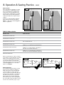
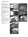
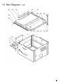
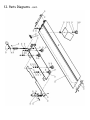
1
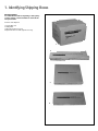
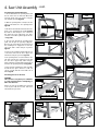
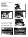
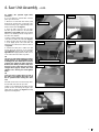
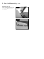
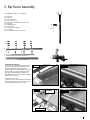
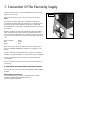
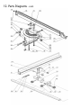
Original Instruction Manual
TS200C
Compact Cast Iron Table Saw
IMPORTANT
For your safety read instructions
carefully before assembling or using
this product. Save this manual for
future reference.
Version 2.1
February 2010
Woodworking Machines & Accessories
Record Power Ltd
Unit B, Adelphi Way
Staveley S43 3LS
Telephone: 01246 561 520
Fax: 01246 561 537
Email: [email protected]
www.recordpower.co.uk
HEALTH AND SAFETY GUIDELINES
Always follow the instructions provided with the manual. Always wear safety glasses when using woodworking
equipment. Always disconnect the power before adjusting any equipment. Failure to observe proper safety
procedures and guidelines can result in serious injury.
WARNING: Do not allow familiarity (gained from frequent use of your machine and accessories) to become
commonplace. Always remember that a careless fraction of a second is sufficient to inflict severe injury.
Always wear safety glasses when
using woodworking equipment.
Always read the instructions
provided before using
woodworking equipment.
Contents
Terms & Conditions Of Usage
Health & Safety Guidance
page 3
Additional Safety Instructions For Table Saws
page 4
Record Power Guarantee
page 5
EU Declaration Of Conformity
page 33
User Manual
Consumable Spare Parts
Quick Find
1.
Identifying Shipping Boxes
page 6
2.
Getting To Know Your Table Saw
page 7
3.
Machine Specification
page 7
4.
Saw Unit Assembly
page 8
5.
Rip Fence Assembly
page 15
6.
Final Assembly
page 17
7.
Connection Of The Electricity Supply
page 18
8.
Operation & Sawing Practice
page 19
9.
Dust Extraction page 23
10.
Maintenance
page 24
11.
Parts Diagrams
page 26
12.
Parts List
page 26
Part Description
Part Number
Table insert
Blade guard
Blade guard extraction hose
Riving knife
Handwheel
Fence extension
Ratchet handle
Fence lock knob
Fence end gap
Stop lock knob
93
1
2
86
78
191
188
206
176
148
Health & Safety Guidance
READ ALL THE INSTRUCTIONS IN THIS MANUAL CAREFULLY
BEFORE ASSEMBLY, INSTALLATION AND USE OF THIS PRODUCT.
KEEP THESE INSTRUCTIONS IN A SAFE PLACE FOR FUTURE
REFERENCE.
WARNING: When using electric tools, basic safety precautions should
always be followed to reduce the risk of fire, electric shock and
personal injury.
Safe Operation
1. Eye Protection
The operation of any power tool can result in
foreign objects being thrown into your eyes, which can result in severe eye
damage. Always wear safety glasses or other suitable eye protection. Wear
safety glasses at all times. Everyday glasses only have impact resistant
lenses. They are not safety glasses which give additional lateral protection.
It is also important to wear ear protectors when operating the table saw.
2. Keep work area clear.
Cluttered areas and benches invite accidents and injuries.
15. Maintain tools with care.
• Follow instructions for lubrication and changing accessories.
• Inspect electric cords periodically and, if damaged, have them repaired by
an authorized service facility or qualified electrician.
• Inspect extension cords (if used) periodically and replace if damaged.
Always use properly rated extension cord.
16. Disconnect Machine.
When not in use, before servicing, changing blades etc. disconnect the
machine from the power supply.
17. Never leave machine running unattended.
Turn power off, do not leave machine until it comes to a complete stop.
18. Remove adjusting keys and wrenches.
ENSURE that all adjusting wrenches and keys are removed before switching
the machine ‘ON’.
19. Avoid unintentional starting.
Ensure the switch is in the “STOP” position before turning on the power
from the main electricity supply. Your Record Table saw already incorporates
low voltage protection. This means the machine will not automatically start
up after say a power cut, unless you first reset the start switch.
3. Consider work area environment.
Do not expose the machine to rain or damp conditions.
• Keep the work area well lit.
• Do not use the machine in the presence of flammable
liquids or gases.
20. Out-door Extension Leads.
Your machine should not be used outdoors.
4. Guard against electric shock.
Avoid body contact with earthed or grounded surfaces.
22. Check for damaged parts.
• Before use of the machine, it should be carefully checked to determine
that it will operate properly and perform its intended function.
• Check for alignment of moving parts, binding of moving parts, breakage
of parts, mounting and any other conditions that may affect its operation.
• A guard or other part that is damaged should be properly repaired or
replaced by a qualified person unless otherwise indicated in this instruction
manual. Have defective switches replaced by a qualified person.
• Do not use the machine if the switch does not turn on and off.
5. Keep other persons away (and pets).
Do not let persons, especially children, not involved in the work, touch the
machine, or extension cord (if used) and keep visitors away from the work
area.
6. Store idle tools.
When not in use, tools should be stored in a dry, locked- up place, out of
reach of children.
7. Do not force the machine.
It will do the job better and work more safely if operated at the speed at
which it was intended.
8. Use the right tool.
• Do not force small tools to do the job of a heavy-duty tool.
• Do not use tools for purposes other than those for which they were
intended.
9. Dress properly.
• Non-slip footwear is recommended.
• Do not wear loose clothing, neckties or jewellery; they can be caught in
moving parts.
• Roll up long sleeves above the elbow.
• Wear protective hair covering to contain long hair.
10. Use protective equipment
• Use safety glasses. (See note 1. above)
• Use face or dust shield if cutting operation creates dust.
• Use ear plugs or ear defenders when the machine is in use
11. Connect dust extraction equipment.
(See section 9, page 22)
12. Do not abuse the cord.
Never yank the cord to disconnect it from the socket. Keep the cord away
from heat, oil and sharp edges.
13. Do not overreach.
Keep proper footing and balance at all times.
14. Secure work.
Ensure that your work piece is properly held before
starting to cut.
21. Stay alert.
Watch what you are doing, use common sense and do not use the machine
when you are tired.
23. Warning!
• The use of any accessory or attachment, other than those recommended
in this instruction manual, or recommended by our Company may present a
risk of personal injury.
24. Have your machine repaired by a qualified person.
• This electric machine complies with the relevant safety rules. Only
qualified persons using original spare parts should carry out repairs. Failure
to do this may result in considerable danger to the user.
25. This machine is designed for cutting wood.
• Do not use for cutting any material other than wood.
Maintenance and Servicing
This machine requires very little maintenance. This handbook gives clear
instructions on installation, set up and operation.
Read these instructions carefully. Remember always to switch off and
unplug from the main electricity supply before carrying out any setting up
or maintenance operations.
Should you need advice on the repair or maintenance of this product, our
Customer Service Department can be contacted on 01246 561 520 and will
be happy to assist you.
Record Power Health & Safety Guidance v1.0
2
3
Additional Safety Instructions for Table Saws
SAFETY IS A COMBINATION OF OPERATOR
COMMON SENSE AND ALERTNESS AT ALL TIMES
WHEN THE TABLE SAW IS BEING USED.
WARNING: FOR YOUR OWN SAFETY, DO NOT ATTEMPT TO OPERATE
YOUR TABLE SAW UNTIL IT IS COMPLETELY ASSEMBLED AND INSTALLED
ACCORDING TO THE INSTRUCTIONS.
SAFE OPERATION
1. The table saw should be bolted to the floor where possible.
2. If you are not thoroughly familiar with the operation of table saws,
obtain advice from your supervisor, instructor, or other qualified person or
contact your retailer for information on training courses. Do not use this
machine until adequate training has been undertaken.
3. Never turn the machine ‘ON’ before clearing the table of all objects
(tools, scrap pieces etc.)
4. Ensure that:
(i) the voltage of the machine corresponds to the mains voltage.
(ii) To use an earthed power source (wall socket).
(iii) The cord and plug are in good condition, i.e. not frayed or damaged.
(iv) No saw teeth are missing and the blade is not cracked or split.
Otherwise replace blade.
(v) The blade is aligned.
5. Never start the machine with the saw blade pressed against the
workpiece.
6. Never apply sideways pressure on the blade.
7. Care must be taken when cutting wood with knots, nails or cracks in it
and / or dirt on it.
8. Never leave the machine running unattended.
9. Do not use saw blades which are damaged or deformed.
10. Ensure the selection of the saw blade is suitable for the material to be
cut.
11. If the electrics are damaged, parts must only be replaced by a qualified
electrician.
12. Never use a long extension cable.
13. Always use a push stick and keep hands clear of the blade.
14. Never remove the crown guard or riving knife. These are there to
protect the user.
15. WARNING LABELS – It is important that labels bearing Health & Safety
Warnings are not removed or painted over. New labels are available from
Customer Services.
16. MECHANICAL SAFETY – The security of all clamps and work holding
devices should be checked before switching on.
17. WOOD DUST – The fine particles of dust produced in cutting operations
are a potential health risk. Some imported hardwoods do give off highly
irritant dust which causes a burning sensation. We strongly recommend
the use of a dust collector and dust mask/visor. Our Customer Services
Department will also be happy to advise you on the correct unit for your
needs.
18. This machine falls under the scope of the ‘Health & Safety at Work etc.
Act 1974’, and the ‘Provision & Use of Work Equipment Regulations 1998’.
We recommend that you study and follow these regulations. For further
help on any of the above matters please contact our Customer Services
Department at :Tel: 01246 561 520 Fax: 01246 561 536
WARNING: Do not allow familiarity (gained from frequent use of your
machine) to cause complacency. Always remember that a careless fraction
of a second is sufficient to inflict severe injury.
Record Power Guarantee
1. INTRODUCTION
1.1 We supply machinery through a network of dealers and authorised
distributors and you should be aware that your contract of sale is with the
retailer from whom you purchased this product. 1.2 If you are not satisfied with this product you should in the first instance
approach the retailer from whom you purchased it.
1.3 Customers have statutory rights to protect them and information on
this can be found at the Citizens Advice Bureau or on such web-sites as that
operated by the DTI (http://www.dti.gov.uk)
1.4 Returning your guarantee card will speed up the claims procedure
and can be very helpful as a proof of purchase should the initial receipt be
mislaid or damaged. We recommend that this is returned as close to your
original purchase date as possible.
1.5 Correct installation, set-up, adjustment and routine maintenance of
the machine are the responsibility of the end-user and problems arising
from incorrect set-up, adjustment or maintenance are not covered by the
terms of this guarantee. However support is available in the first instance
from the retailer who supplied you and free technical support is available
from Record Power on 01246 561 520 during office hours and from an
extensive knowledge base on our website www.recordpower.co.uk. We
also recommend that those users who have not had suitable training in
the safe use of machinery should seek such training locally before using or
attempting to set up and adjust any machinery (please contact your retailer
for recommendations in your local area).
2. GUARANTEE
2.1 In addition to the above Record Power guarantees that for a period of
5 years from the date of purchase the components of this product will be
free from defects caused by faulty construction or manufacture.
2.2 During this period Record Power will repair or replace free of charge
any parts which are proved to be faulty in accordance with paragraph 2.1
above provided that:
2.2.1 You follow the claims procedure set out below;
2.2.2 We are given a reasonable opportunity after receiving notice of the
claim to examine the product. 2.2.3 If asked to do so by us, you return the product to Record Power's
premises or other approved premises such as those of the supplying dealer,
for the examination to take place.
2.2.4 The fault in question is not caused by continuous industrial use,
accidental damage, fair wear and tear, wilful damage, negligence on your
part, incorrect electrical connection, unapproved modification, abnormal
working conditions, failure to follow our instructions, misuse, or alteration
or repair of the product without our approval.
2.2.5 This product has been purchased by you and not used for hire
purposes;
2.2.6 This Guarantee extends to the cost of carriage incurred by you
returning the product to Record Power as long as it is demonstrated that
the defect falls within the terms of this Guarantee and you follow the claims
procedure as outlined below; address below on the last day of this Guarantee at the latest. Late claims
will not be considered.
3.4 We will contact you once we have received your initial written claim. If it is necessary to return the item, in most cases but subject always
to clause 2.2.5, we will arrange for collection or will provide freepost
information to enable return depending on the weight and size of the
product concerned. If the product is to be returned to us, we will agree with
you in advance a Returns Number, to speed tracking of the claim and ensure
the most appropriate method of return to you is used.
4. NOTICE
This Guarantee applies to all goods purchased from an authorised retailer
of Record Power within the United Kingdom of Great Britain and Northern
Ireland. This Guarantee does not confer any rights other than those
expressly set out above and does not cover any claims for consequential
loss or damage. This Guarantee is offered as an extra benefit and does not
affect your statutory rights as a consumer. Additional written copies of this
Guarantee can be obtained by writing to the address below. Please include
a stamped and self addressed envelope for each copy of the Guarantee
requested.
Record Power Ltd.
Unit B, Adelphi Way
Ireland Industrial Estate
Staveley, Chesterfield
S43 3LS
3. CLAIMS PROCEDURE
3.1 In the first instance please contact the retailer who supplied the
product to you. In our experience many initial problems with machines that
are thought to be due to faulty parts are actually solved by correct setting
up or adjustment of the machines. A good dealer should be able to resolve
the majority of these issues much more quickly than processing a claim
under the guarantee.
3.2 If the dealer who supplied the product to you has been unable
to satisfy your query, any claim made under this Guarantee should be
made directly to Record Power at the address set out at the foot of this
Guarantee. The claim itself should be made in a letter setting out the date
and place of purchase, and giving a brief explanation of the problem which
has led to the claim. This letter should then be sent with proof of the
purchase date (preferably a receipt) to Record Power. If you include a phone
number or email address this will help to speed up your claim.
3.3 PLEASE NOTE that it is essential that the letter of claim reaches the
Record Power Guarantee v1.0
4
5
1. Identifying Shipping Boxes
BEFORE ASSEMBLY
It is advisable that before unpacking to have plenty
of paper towels or cloths available to clean off the
rust preservative.
Contents of the shipment:
1. TS200C Table Saw
2. Sliding Table
3. Wheel kit (optional accessory)
4. Right hand extension table (optional accessory)
1
2
3
4
2. Getting To Know Your Table Saw
A
C
D
B
I
E
M
N
J
G
F
K
Shown with sliding table and wheel kit
A
Extraction Hose
G
Switch Unit
B
Blade
I
Extension Table
C
Crown Guard
J
Blade Tilt
D
Rip Fence
K
Cabinet Base
E
Main Table
M
Sliding Table
F
Blade Raise & fall
N
Cross Cut Fence
3. Machine Specification
TS200C SPECIFICATION
Blade size: 250mm
Blade bore: 30mm
Blade speed: 4000rpm
Max width (blade to fence) : 600mm
Table Height : 890mm
Max depth of cut using 250mm blade: 80mm @ 90º / 56mm @ 45º
Extraction ports: 30mm upper, 100mm lower
Motor power (output): 2hp
Weight: 110kg
Dimensions not including the sliding carriage: 900mm (height) x 625mm (width) x 675mm (length)
Dimensions of sliding beam: 1050mm (length) x 215mm (width)
Sliding carriage stroke / max sheet capacity: 620mm
Recommended length of workshop space, full stroke at sheet capacity: 1620mm (approx.)
6
7
4. Saw Unit Assembly
CAUTION
Many of the items are very heavy. We recommend
that assistance is sought before trying to lift the
larger components.
1
4.1 Identification of saw unit components
3
2
1. 2 x Long mid brace supports
2. 2 x Short mid brace support
3. 2 x Long top brace supports
4. 2 x Short top brace supports
5. 4 x Legs
6. 1 x Saw unit
7. 1 x Sliding table
8. 1 x Mitre fence seat
9. 1 x Mitre fence
10. 1x Connector
1
11. 1 x Jubilee clip
12. 1 x Extraction port
13. 1 x Mains cord
14. 1 x Push stick
15. 1 x Crown guard
16. 1 x Aluminum fence & fence carrier
17. 1 x Rip fence scale & extrusion
18. 1 x Extraction hose support w/mounting parts
19. 1 x Front fence bar
20. 1 x Rear rail
21. 2 x Handwheel
22. 1 x Extraction hose
23. 1x Workpiece block
24. 1x Loose bag 1
25. 1x Loose bag 2
4
5
6
7
24
25
9
18
17
10
13
14
15
21
8
22
11
12
20
16
18
23
4. Saw Unit Assembly - cont.
CAUTION
Many of the items are very heavy.
We recommend that assistance is
sought before trying to lift the larger
components.
Fig.4.1
Fig.4.4
Note: When assembling this table saw,
Do not fully tighten the nuts and bolts
until the assembly is complete.
4.2 Stand Assembly
1. Locate the first leg and secure it to one of the
long top brace supports using the nuts, bolts
and washers supplied Fig.4.1 and Fig.4.1B.
2. In the same way, attach the second leg to the
brace support Fig.4.2.
3. Locate the short top brace supports and fix
the to the legs as shown Fig.4.3.
Fig.4.1B
Fig.4.5
Fig.4.2
L O N G M I D B R AC E
SUPPORT
4. Continue in this way until all of the legs and
top brace supports have been fitted Fig.4.4.
5. Locating holes a third of the way down each
leg are for securing the mid brace supports. Fix
the long mid brace supports to the frame using
the nuts, bolts and washers Fig.4.5.
LONG TOP BRACE
SUPPORT
6. Finally, fit the short mid brace support to one
of the shorter sides Fig.4.6.
Note
The side without the short mid brace
support fitted will be referred to as the
front of the stand. This leaves the front
area free for wheel kit operation.
Fig.4.6
Fig.4.3
SHORT TOP BRACE
SUPPORTS
FRONT
8
9
4. Saw Unit Assembly - cont.
4.3 Fitting the optional wheel kit
1. On the underside of the operating frame, find
the two raised areas on either side. Mount the
two back wheels and secure in place using the
nuts and bolts provided Fig.4.7A.
Fig.4.7A
2. With the operating frame in hand, locate the
release pedal and fix it to the operating frame
Fig.4.7B.
Fig.4.7F
RAISED AREAS
PIN & WASHER
3. Take the two front wheels and mount and secure
them to the operating frame pedal Fig.4.7C.
Now slide an axle through on one of the front
legs and hook a brace support bar on it. Place
a washer on and slide a pin throughout the axle
end Fig.4.7D.
4. Pass the axle through the operating frame
pedal and through the opposing legFig.4.7E.
Once the axle is through the opposing leg hook
the remaining brace support bar on the axle
and secure with a washer and pin as previous
Fig.4.7F.
Fig.4.7G
Fig.4.7B
RELEASE PEDAL
5. Now pass the remaining axle through the rear
of the stand and hook the brace support bar
with washer and pin as previous. Fig.4.7G.
6. The operating frame can now be fitted to the
axle and secured to the opposing rear leg with
the other brace support bar, washer and pin.
Ensure when this operating frame is fitted that it
sits below the operating frame pedal Fig.4.7H.
Fig.4.7C
7. Once the frame is upright, the whole assembly
should fall into place. However it will not
operate correctly until the actual table saw is
fitted. Fig.4.7I.
Fig.4.7H
4.4 Fitting the saw to the base
CAUTION
This saw unit is very heavy. It is advisable
to seek assistance before attempting to
lift it onto the base.
Lift the saw onto the assembled open stand and
secure in place with the four hex bolts from
underneath the open stand.
Fig.4.7D
AXLE
PIN
WASHER
BRACE SUPPORT BAR
Fig.4.8
Fig.4.7E
Hex. head bolts
Fig.4.7I
BRACE SUPPORT
BAR
4. Saw Unit Assembly - cont.
4.5 Fitting the handwheel
Attached the handwheel for blade tilt and rise &
fall with Hex. wrench. Fig.4.9A
Fig.4.9A
4.6 Fitting the extraction hose
1. Unfasten the dust extraction hose from
underneath the main saw unit and thread
through the extraction hole in the side on the
machine Fig.4.9B.
2. Fit the extraction port over the end of the
hose and clip into place Fig.4.10.
3. Secure the extraction connector to the end of
the hose using the jubilee clip Fig.4.11.
Fig.4.9B
Fig.4.10
Extraction port
Fig.4.11
4.7 Fitting the sliding table
1. Before fitting the sliding table onto the table saw. Check if the
saw blade is square to the table.
Jubilee clip
2. Wind the blade up through the table slot . Check if the blade
is parallel with the table slot and make sure that the gap
shown is minumum 3mm. Fig.4.12
Extractor connector
3. If the table is out of parallel with the blade, loosen the four Allen
bolts to move the table for correction. Fig.4.13.
Fig.4.12
Fig.4.13A
Allen bolts and washers
10
11
4. Saw Unit Assembly - cont.
4.8 Adjusting the sliding table
The Sliding table is pre-adjusted in the factory. If it is out of
parallel or not sliding smoothly, you can make adjustments
according to the instructions below.
Fig.4.14
1.Checking the Height
Put the straight gauge on the sliding table and cast table
to check if the sliding table is the same height as the main
table (Fig 4.13). If it is not, you can adjust the four guide
wheels to correct. Two of them can only adjust vertically.
The other two are eccentric wheels and can adjust both
vertically and horizontally
(Fig 4.15).
2. To adjust the height of the two inside wheels. Adjust the height
of the guide wheels to the correct position with a screwdriver and a
wrench(Fig. 4.16).
Fig.4.15
Fig.4.16
For vertical adjustment
For vertical and horizontal adjustment
3. To adjust the height of the outside wheels, loosen the nut at the
end of wheel shaft with a screwdriver and a wrench through the
adjusting window. Then adjust the self-lock nut to achive the correct
height with a wrench.(Fig. 4.17)
4. When the tables are at the correct height, check the sliding table to
see if it moves smoothly. If not, loosen the bottom lock nut through the
window (Fig. 4.17) and using a screwdriver rotate the eccentric wheels
to correct. (Fig. 4.18)
Fig.4.18
Fig.4.17
Self lock nut
4. Saw Unit Assembly - cont.
4.8 Fitting the optional right table
extension
If you are fitting the optional table extension
please proceed as below.
1. Take the 4 hex head bolts and washers, wind
them into the location holes on right side of the
main table leaving a gap of approximately 10mm
between washer and table Fig.4.21.
Fig.4.21
Fig.4.25A
Approx. 10mm
2. Hook the table extension onto the bolts
that have just been attached to the main table
Fig.4.22A and Fig.4.22B. Tighten the mounting
bolts to secure the table, but leave enough slack so
the table can be adjusted.
3. Taking a suitable straight edge, check the level
of the extension table to the main table Fig.4.23.
To adjust the table; first lift the table extension
so it sits slightly proud of the main table and
tighten the hex head bolts the table is hooked on
to Fig.4.22A.
Fig.4.22A
Fig.4.25B
4. To flatten the table, take a mallet and a flat
wooden block and tap down on the extension
table Fig.4.25A until level with the main table
Fig.4.25B. When tapping the block strike as close
to the seam between the tables as possible.
TIP
The success of the table levelling procedure
largely depends on the adjustment of the
mounting bolts. The smaller the movement
required, the tighter the bolts should be.
However, the whole procedure really does
depend on feel. If the table isn't moving
enough when tapped, slacken the bolts
slightly. If it is moving too much tighten
them.
Table hooked on to the bolts
Fig.4.22B
TIP
Level one end at a time, when one end of
the table is level tighten that bolt to lock
this in position before setting the other
end.
If the table has moved too low raise back up above
the main table and restart the procedure.
5. When you are satisfied that the tables are level
perform one last check along the length of the
tables with the straight edge Fig.4.23 and fully
tighten the mounting bolts.
Fig.4.23
12
13
4. Saw Unit Assembly - cont.
4.9 Fitting the crown guard
Hook the crown guard into the keyway on top
of the riving knife Fig.4.28 and tighten into
position Fig.4.29.
Fig.4.28
Fig.4.29
5. Rip Fence Assembly
9
5.1 Identification of rip fence components
1. 4 x Hex. nuts
2. 8 x Washers
3. 1 x Front fence bar
4. 2 x Hex. socket screws
5. 2 x Hex. bolts, washers(4) & hex. nuts (each)
6. 1 x Rear rail
7. 1 x Aluminum fence
8. 1 x Fence carrier
9. 1 x Extraction hose support
10. 1 x 'U' Piece
11. 2 x Pan head screw, hex. nuts (each)
10
11
1
2
3
4
5
6
8
7
5.2 Fixing the fence bar
Locate fence bar onto the table Fig.5.1A and fix
with the two fence fixing bar nuts and washers
(four fence fixing bar nuts and washers for
optional table extension bar). With those nuts and
washers in place on the other side of the table
Fig.5.1B Secure the fixing Fig.5.2A but do not
fully tighten yet as they may need to be adjusted
later in the setup process.
Fig.5.1B
Fig.5.2A
5.3 Fixing the fence scale
Locate fence scale onto the table Fig. 5.2B and fix
with two pan head screws (four pan head screws
for optional table extension fence scale).
Fig.5.1A
FIXING NUTS
& WASHERS
Fig.5.2B
FENCE BAR
14
15
5. Rip Fence Assembly - cont.
5.3 Fitting the fence carrier
Fasten the fence holding fixtures through the
fence carrier casting Fig.5.3. Locate the fence
carrier on to the fence rail Fig. 5.4
5.4 Fitting the rip fence
Now simply slide the rip fence on to the fence
carrier and tighten the holding fixtures. Screw in
the lock knob to secure the position of the fence
on the rail Fig 5.6. The fence can be used in the
upright position as shown or the fence can be
attached to the carrier using the other "T" slot
giving another position.
5.5 Fence alignment 1
Align the fence assembly in or out until parallel
with the side of the blade by turning the
adjustment nuts and the fence bolts accordingly.
If the fixing nuts have been tightened, these will
need slackening off before this adjustment can
be made.
Fig.5.3
HOLDING
FIXTURES
FENCE CARRIER
Fig.5.4
FENCE
ADJUSTMENT NUT
FENCE RAIL
MOVEMENT
Fig.5.5
FENCE RAIL
5.6 Fence alignment 2
Check that the fence is 90 degrees to the
table using a suitable square. If no adjustment
is needed fully tighten the fence bar nuts. If
adjustment is required this is achieved by raising
or lowering either side of the fence rail until the
fence itself is 90 degree to the table. Once set at
90 degree fully tighten the fence bar nuts.
T-SLOT
FENCE RAIL
Fig.5.6
FENCE
ADJUSTMENT
FENCE RAIL
5.7 Fitting the rear fence railLocate rear fence rail onto the table Fig. 5.6. and
fix with two hex. socket screws for the main table
and two hex. bolt, washers and nuts for the table
extension.
6. Final Assembly
Fitting crown guard extraction hose
1. Fit the hose support in the U-piece that has
been fitted in the rear main table or optional
table extension. Fig.6.1.
2. Now attach one end of the hose to the crown
guard Fig.6.2
Fig.6.1
Hose support
3. Hook the hose over the hose support and feed
underneath the table to connect with the main
extraction outlet Fig.6.3
U-piece
Fig.6.2
Fig.6.3
Main extraction
outlet
16 17
7. Connection Of The Electricity Supply
Once the machine has been correctly assembled and set up the electricity
supply can be connected.
Connect the two pin plug socket on the end of the flex to the switch
Fig.7.1.
The machine can only be connected to a single phase supply. Before
connecting the electrical supply ensure that it is the correct voltage, phase
and frequency, and that it has sufficient capacity for the machine. The
relevant information can be found on the rating plate located on the rear of
the machine.
Machines supplied for use in the UK are fitted with a BS1363 plug fitted
with a 13 amp fuse. Ensure that you use the appropriate plug for use in
other countries. If the plug fitted to the machine is changed for any reason,
the wires in the mains lead are coloured in accordance with the following
code:
Green and yellow:
Blue:
Brown:
Earth
Neutral
Live
As the colours of the wires in the mains lead may not correspond with
the coloured markings identifying the terminals on your plug, proceed as
follows:
The wire coloured green and yellow must be connected to the terminal
marked ‘E’ or by the earth symbol ~ or coloured green; or green and yellow.
The wire coloured blue must be connected to the terminal marked ‘N’
coloured black.
The wire coloured brown must be connected to the terminal marked ‘L’ or
coloured red.
IT IS IMPORTANT THAT THE MACHINE IS EFFECTIVELY EARTHED.
If in doubt about the connection of the electrical supply consult a qualified
electrician.
RCD (Residual Current Device)
For your additional safety we always recommend the use of an RCD
(sometimes called Residual Current Circuit Breaker
or Earth Leakage Circuit Breaker).
Fig.7.1
8. Operation & Sawing Practice
Basic circular saw principles
• The blade rotates on a spindle, and breaks
through the timber, cutting on a continuous
stroke Fig.8.1.
Fig.8.1
• Slowly feed the workpiece towards the blade
Fig.8.1, let the blade do the cutting it is not
necessary to force the material. When feeding
towards the blade hold the workpiece firmly and
use the table to provide support. Always use a
push stick, keeping your hand well away from
the blade.
• For best results the blade must be sharp and
in good condition. A damaged or worn blade
should always be replaced.
• Select the right blade for the job, depending
on the type of material and the cut to be made
see table 2 (page 31).
TABLE 1: Basic applications
RIPPING
When the timber is cut with the
grain, use the rip fence for this
application
CROSS CUTTING
When the timber is cut across the
grain, use either mitre fence or
sliding carriage for this application
PANEL SIZING
Dimensioning man made sheet
material. Use either the rip fence or
sliding carriage for this application
BEVELLED EDGE
When a bevelled (angled) edge is
required to the workpiece tilt the
blade and pass the timber though.
If the rip fence is being used with
the blade is tilted the auxiliary
fence should be used in the low
position to prevent it fouling on the
blade when tilted.
18
19
8. Operation & Sawing Practice - cont.
Blade selection
Before undertaking any application on a table
saw is important to consider blade selection.
There are many blade types available and it
is important to select the right blade for the
job. The TS200C is supplied with a good multipurpose blade, but for specialist applications
a blade with a different tooth pattern may be
required.
Fig.8.2
Fig.8.3
A table saw can be fitted with two different
styles of blade: An alternative bevel blade
Fig.8.2 or a triple chip tooth blade Fig.8.3. See
table 2 for applications
TABLE 2: Blade selection
BLADE TYPE
APPLICATION
24 TOOTH
Ideal for deep ripping softwoods
ALTERNATE BEVEL POSITIVE HOOK
30 TOOTH
Ideal for deep ripping hardwoods
ALTERNATE BEVEL POSITIVE HOOK
36 TOOTH
ALTERNATE BEVEL POSITIVE HOOK
General purpose, suitable for ripping and cross cutting
both soft and hardwoods.
40 TOOTH
Suitable for cross cutting both soft and hardwoods.
ALTERNATE BEVEL POSITIVE HOOK
40 TOOTH ANTI KICKBACK
ALTERNATE BEVEL SEMI-POSITIVE HOOK
80 TOOTH
ALTERNATE BEVEL POSITIVE HOOK
80 TOOTH
Suitable for cross cutting both soft and hardwoods,
provides protection from kickback.
Suitable for cross cutting and gives a fine finish on
man-made sheet material and laminates
Suitable for cross and cutting gives a fine finish on
man-made sheet material and laminates. Triple chip
teeth reduce breakout on the material.
TRIPLE CHIP POSITIVE HOOK
When choosing a blade for a table saw always
ensure that it is a hard bodied blade, soft bodied
blades are only suitable for power tools. The
easiest way to tell the difference between hard
and soft bodied blades is that hard bodied
blades have movement slots cut into the gullets
of the blade Fig.8.4, where as soft bodied
blades are solid Fig.8.5.
Blade maintenance
It is essential that whichever blade is selected
that it is in good condition. Any build up of
timber resin near the teeth of the blade will
cause the workpiece to stall or stick. These
deposits should removed with white spirit after
cleaning it is also advisable to coat the blade
with silicone spray. Do not use any product
which contains oil on the blade as this will
attract dirt. Never try to clean a moving blade.
The saw should be stopped, the blade removed
and the resin removed with a proper scraper.
Fig.8.4
HARD BODIED
Suitable for table saws
Fig.8.5
SOFT BODIED
Unsuitable for table saws
8. Operation & Sawing Practice - cont.
Workpiece Support
Good workpiece support is essential on a table
saw. Additional supports should always be used
if the workpiece overhangs the table. Roller
stands are ideal for this purpose and should be
used at both infeed and outfeed ends of the
machine.
A rip fence, cross cut fence or mitre fence should
be used to support the workpiece during the
cutting action Fig 8.6A, B & C.
Fig.8.6A
Fig.8.6B
During angled or shallow work the auxiliary
fence should be re-fitted into the low position to
aid the use of a push stick and to stop the blade
fouling on the fence Fig 8.7A & B.
Use Of A Push Stick
A push stick should always be used when
making any cut less than 300mm in length or
when feeding the last 300mm of a longer cut.
the leading hand should never be closer than
is necessary to the front of the saw and hands
should never be in line with the saw blade.
A push-stick should always be used to remove
the cut piece from between the saw blade and
fence.
Fig.8.6C
Fig.8.6A
Setting The Saw Guard
The saw guard should be adjusted as close to
the workpiece as possible Fig 8.8.
Setting The Rise & Fall
The rise and fall must be adjusted so the saw
guard is as close to the workpiece as possible.
However the teeth should project through
the top of the workpiece at all times. Fig 8.8.
The rise and fall is operated using the large
handwheel on the front of the machine Fig 8.9.
Setting The blade tilt
To tilt the blade in order to achieve a bevelled
edge unlock the lock knob and turn the small
handwheel until blade is positioned as required
Fig 8.9.
Fig.8.7B
Fig.8.8
Fig.8.9
Rise & fall
Blade tilt
20
21
9. Operation & Sawing Practice - cont.
Kickback
Kickback can occur as the material passes
through the saw blade. When the timber is past
the centre point on the blade the teeth are
moving upwards and towards the user Fig.9.12.
If the timber closes onto these upward moving
teeth the timber will kickback.
The way to overcome kickback is to prevent
the timber from closing up onto the blade. To
prevent this from happening the fence must be
set correctly, if the auxiliary fence is set too far
along it can force the timber into the blade and
cause kickback Fig.9.13. By setting the auxiliary
fence in front of the blade centre Fig.9.14. the
timber has space to move into as the cut is
made. Kickback is now far less likely occur as
the timber isn't being forced into the upward
moving blade.
Pull saw
The TS200C features a pull saw function which is
ideal for cross cutting small workpieces, accurate
repetitive cuts can easily and safely be achieved.
Fig.9.15
Fig.9.12
Centre point
of the blade
Positive angle
stop screw
Workpiece
Fig.9.13
Fig.9.16
Riving knife
-45º
Positive
angle stop
screw
Auxiliary
fence
Slide lock
knob
Angle
lock
handle
Positive angle catch
00º Positive
angle stop
screw
+45º
Positive
angle stop
screw
The first aspect which should be understood is
the mitre fence hold down clamp. Fig.9.15 Fig.9.17.
Blade centre
point
Fig.9.17
Positive
angle catch
Fig.9.14
Riving knife
Auxiliary
fence
Blade centre
point
Positive angle
stop screw
10. Dust Extraction
10.1 The importance of dust extraction
Before the machine is started, ensure that adequate dust extraction
provisions have been installed. Dust extraction is extremely important not
only for health and safety but also for the correct upkeep of the machine.
Saw dust can cause the machine not to operate properly or even fail
completely. It is paramount that the extraction port is kept free of waste
so mounds of sawdust do not build up around the lower band wheel and
blade guides. It is advisable before starting the machine to inspect the
internals of the machine and ensure there isn’t excessive dust build up. By
keeping the machine free of large amounts of waste the performance will
be enhanced. Even with adequate extraction there will be partial build up
of dust inside the machine, this should be cleaned out as part of the regular
maintenance schedule.
If a large amounts of MDF or toxic woods are to be cut we recommend that
there is a good ventilation system in place and that a P2 particle mask is
worn as minimum protection.
RSDE3 High Filtration Dust Extractor
Bag type extractor, 80 litre capacity, single 1kw motor, suitable for
intermittent use i.e must be switched off for 20 minutes per hour.
DX4000 High Filtration Dust Extractor
Drum type extractor, 80 litre capacity, Twin 1kw motor, suitable for heavy
usage i.e if one motor is switched off for 20 minutes then the other can
be used thus enabling continuous usage. Or both motors can be used
simultaneously giving maximum suction but in this mode the extractor must
be switched off for 20 minutes every hour.
DX5000 High Filtration Dust Extractor
Bag type extractor, 200 litre capacity, Twin 1kw motor, suitable for heavy
usage i.e if one motor is switched off for 20 minutes then the other can
be used thus enabling continuous usage. Or both motors can be used
simultaneously giving maximum suction but in this mode the extractor must
be switched off for 20 minutes every hour.
10.2 Record Power Extractors
Record Power offer a range of high quality dust extractors, starting at the
single motor 45 litre RSDE1 right up to the 200 litre twin motor DX5000.
We offer both drum and bag type extractors and all models provide high
filtration down 0.5 micron providing protection from harmful fine dusts such
as MDF.
RSDE1 High Filtration Dust Extractor
Drum type extractor, 45 litre capacity, single 1kw motor, suitable for
intermittent use i.e must be switched off for 20 minutes per hour.
RSDE2 High Filtration Dust Extractor
Drum type extractor, 50 litre capacity, single 1kw motor, suitable for
intermittent use i.e must be switched off for 20 minutes per hour.
RSDE1
Bandsaws
Circular saws
Sanders
Intermittent usage
RSDE2
3
Recommended
3
Recommended
RSDE3
DX4000
3
Recommended
Bandsaws
Circular saws
Sanders
Heavy usage
Planer Thicknessers
Spindle Moulders
Universals
Intermittent usage
Dust Extraction
System
Intermittent usage
Recommended
3
Recommended
3
Can be used
Planer Thicknessers
Spindle Moulders
Universals
Heavy usage
3
3
Can be used
3
Can be used
3
Can be used
DX5000
CX2000
CX2600
3
Recommended
3
Recommended
3
Recommended
3
Recommended
3
Recommended
3
Recommended
3
Recommended
3
Recommended
3
Recommended
22 23
11. Maintenance
Changing the blade
1. To change the blade; first remove the crown
guard by slackening off the locking screw and
unhooking from the riving knife Fig.11.1.
Fig.11.1
Fig.11.5
2. Loosen the 3 screws on the table insert
Fig.113 and remove the insert.
3. Remove the sliding table stop and remove the
sliding table Fig.11.2A/11.2B to give access to
the extraction panel. Loosen the holding screw
on the extraction panel and pull the panel away
from the blade to create a space between them
Fig.11.5.
4. Place the tommy bar in the location hole
behind the blade Fig.11.7.
Locking screw
Fig.11.2A
Fig.11.6
Fig.11.2B
Fig.11.7
5. Using a spanner, turn the nut clockwise to
loosen it. At this point the tommy bar should
have turned with the blade and be tight up
against the spindle housing creating an anchor
to turn against Fig.11.4.
6. Remove the nut, washer and bush from the
blade spindle Fig.11.6.
NOTE
Take care not to drop the nut down into
the unit.
7. It is now possible to remove the blade from
the spindle Fig.11.7.
The blade can now be replaced.
8. Feed the new blade on to the spindle ensuring
that it is seated firmly on the hub.
9. Replace the bush, washer and nut and using
a spanner, turn the nut anti-clockwise to tighten
it. At this point the tommy bar should have
turned with the blade and be tight up against
the spindle housing to create an anchor to turn
against.
10. Replace the table insert and retighten the
screws to hold it in place.
Fig.11.3
11. Re-fit the sliding table and secure by fitting
the sliding table stop.
Fig.11.4
11. Maintenance - cont.
NOTE
To adjust the belt tension of the, motor
it may be necessary to remove the tables
to access the inside of the saw unit.
Fig.11.10A
Fig.11.13
Bolt 1
Tensioning the belt
1. When tensioning the belt the three motor
mounting bolts must be slackened Fig.11.10A
and Fig.11.10B.
2. Slacken the three bolts and pivot the motor
to the right to increase tension Fig.11.13. When
desired tension is achieved, retighten the three
bolts to secure the setting.
Bolt 2
Fig.11.10B
Bolt 3
24 25
12. Parts Diagrams
12. Parts Diagrams - cont.
26 27
12. Parts Diagrams - cont.
12. Parts Diagrams - cont.
28 29
12. Parts Diagrams - cont.
13. Parts List
Ref No.
Description
Ref No.
Description
1
2
3
4
5
6
7
8
9
10
11
12
13
14
15
16
17
18
19
20
21
22
23
24
25
26
27
28
29
30
31
32
33
34
35
36
37
38
39
40
41
42
43
44
45
46
47
48
49
50
51
52
53
54
55
56
Blade guard assembly
Dust collecting tube
Blade
Mount adjusting base
Mount base
Lock handle assembly
Flat washer 8
Rotating support base
Mount base
Shaft
Rubber washer
Adjusting washer
Bearing 80103C
Retaining ring
Big quill tube
Shaft pulley
Quill tube
Bearing 80301C
Adjusting wheel
Hex. Nut M8
Big washer
Flat washer 8
Multi-belt
Hex. Bolt M6X20
Flat washer 6
Flat washer 6
Angle shaft
Hex. Nut M8
Flat washer 8
Tube
Washer
Retaining ring
Screw shaft
Screw tube
Tube
Position screw
Washer
Dust collector
Hex. Bolt
Hex. Nut M10X1.5
Flat washer
Blade collar
Circlip 32mm
Washer
Screw M6X20
Hex. Nut M6
Flat washer 6
Hex. Nut M8
Flat washer 8
Tube
Quill tube II
Position bolt
Hex. Nut M6
Lock nut M6
Screw M6X35
Pessure plate
57
58
59
60
61
62
63
64
65
66
67
68
69
70
71
72
73
74
75
76
77
78
79
80
81
82
83
84
85
86
87
88
89
90
91
92
93
94
95
96
97
98
99
100
101
102
103
104
105
106
107
108
109
110
111
112
Tube
Quill tube I
Screw M8X20
square nut
Flat washer
Spring washer 8
Angle rotating shaft
Tube circlip
Dust collecting tube
Motor
Motor pulley
Washer
Big washer
Hex bolt
Motor mounting plate
Gear rod
Circlip 12mm
Circlip 22mm
Bearing
Bearing base
Screw
Big handwheel
Wheel handle
Screw
Screw
Rod
Hex socket head screw M6X10
Mount, riving knife
Guide plate assembly
Guide plate
Direction washer
Pressure plate
Flat washer 10
Hex nut M10
Spring washer 10
Main table
Table insert
Screw M5X8
Table, right side
Hex. Bolt M8X12
Flat washer 8
Hex. Nut M5
Flat washer 5
Support bracket
Semicircular bracket
Pan head screw M5X10
Staff guage
Pan head screw M6X16
Hex socket head screw M8X16
Rear rail
Screw M4X8
Flat washer 4
Front panel
Cabinet Assembly
Switch
Screw M4X60
13. Parts List - cont.
Ref No.
Description
Ref No.
Description
113
114
115
116
117
118
119
120
121
122
123
124
125
126
127
128
129
130
131
132
133
134
135
136
137
138
139
140
141
142
143
144
145
146
147
148
149
150
151
152
153
154
155
156
157
158
159
160
161
162
163
164
165
166
167
168
Tapping screw ST4.2X9.5
Carrier cover
Carriage bolt M8X16
Flat washer 8
Spring washer 8
Pan head nut M8
Hex bolt M6X16
Flat washer 6
square nut
Cover, fence knob
Body, fence knob
Bracket
Tube
Eccentric adjuster
Flat washer 8
Spring washer 8
Hex. Nut M8
Support, sliding wheel
Base, sliding table
Sliding table
Safety switch
Hex. Bolt M4X30
Hex. Nut M4
Flat washer 4
Pan head screw M4X10
Shield bracket
Bracket
Countersunk head screw M6X16
Position pin
Hex. Nut M12X1.5
Spring
Pin roll 3x16
Position collar
shaft
Hex. Nut M6
Handle knob
Carriage bolt M8X16
Flat washer 8
Hex. Nut 8
Front brace
Shelf beam
Support leg
Rubber foot
Side beam
Side brace
Push bracket
Rotate Wheel
Support bracket
Spring bracket
Hex. Bolt M8X20
Flat washer 8
Hex. Nut M8
Wheel
Roll pin 3x35
Flat washer 10
Shaft
169
170
171
172
173
174
175
176
177
178
179
180
181
182
183
184
185
186
187
188
189
190
191
192
193
194
195
196
197
198
199
200
201
202
203
204
205
206
Position bracket
Fence
Carriage bolt M6X30
T bracket
Mitre gauge
Countersunk head screw M6X70
Nut
Right end cap
Tapping screw ST4.2X9.5
Left end cap
Countersunk head screw M6X50
Flat washer 6
Flat washer 6
Flat washer 4
Screw M4X12
Indicator base
Roll pin
Indicator
Screw M4X8
Adjusting handle
Hex. Nut M4
Screw M4X16
Fence, "L" shape
Carriage bolt M6X35
Fence support brace
Flat Washer 6
Nut
Fence base
Micro-adjusting base
Front rail
Hex socket head screw M8X45
Support shaft
Hex. Nut M8
Flat washer 8
Micro-adjusting knob
Flat washer 6
Hex. Nut M6
Lock handle
46
47
EU Declaration of Conformity
Cert No: EU / TS200C / 1
RECORD POWER LIMITED,
Unit B, Ireland Industrial Est.
Adelphi Way, Staveley, Chesterfield S43 3LS
declares that the machinery described: 1.
2.
3. Type: Table Saw
Model No: TS200C
Serial No .........................................................................
Conforms with the following directives:
MACHINERY DIRECTIVE
2006/42/EC
LOW VOLTAGE DIRECTIVE
2006/95/EC
ELECTROMAGNETIC
2004/108/EC
COMPATIBILITY DIRECTIVE
EN 55014-1:2006
EN 61000-3-2:2006
EN 61000-3-3:1995+A1+A2
EN 55014-2:1997+A1
and conforms to the machinery example for which the
EC Type-Examination Certificate No. BM50170597, AN50170595, AE50103166
has been issued by TUV Rheinland Product Safety GmbH,
at: Am Grauen Stein, D-51105. Cologne, Germany and complies with the relevant essential health and safety requirements.
Signed.........................................................Dated: 01/02/2010
Andrew Greensted
Managing Director
32 33
Notes
Notes
Visit
www.recordpower.co.uk
for the full range of
Record Power products.
Woodworking
Machinery
Blades
Craft Accessories
Finishes and Waxes
DVDs
Accessories
rning
Woodtuiques
Techionnto Spindle Turning
ing
urn
odt cts
Wo Projtlee Clock
n
Ma
by
by
ltham
Alan Ho
Step by Step
Guide
Finishing on the
by
Lathe
Alan Holtham
ham
olt
nH
Ala
uct
An Introd
Buyer’s Guide
n with
In associatio
n
ciatio
Series
In association with
with
so
In as
The essential guides
to the most popular
ranges of woodwo
rking machinery
Woodworking Machines & Accessories
Record Power Limited
Unit B, Adelphi Way
Ireland Industrial Est.
Staveley S43 3LS
Telephone: 01246 561 520
Facsimile: 01246 561 537
Email: [email protected]
www.recordpower.co.uk