1
1-8 Appendix
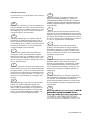
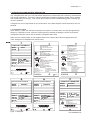
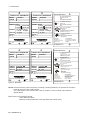
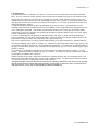
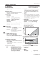
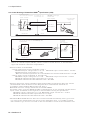
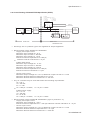
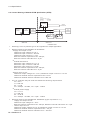
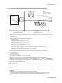
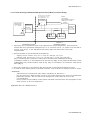
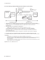
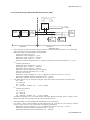
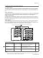
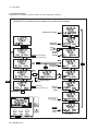
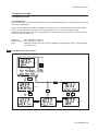
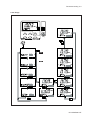
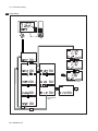
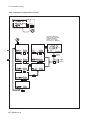
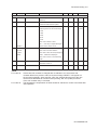
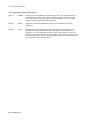
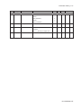
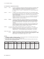
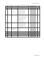
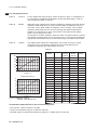
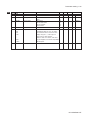
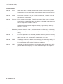
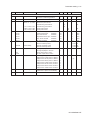
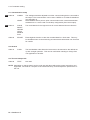
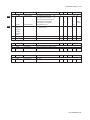
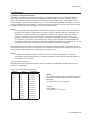
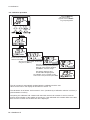
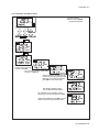
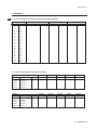
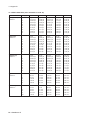
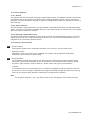
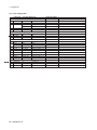
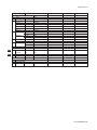
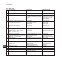
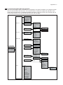
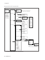
Menu structure for HHT 375 shown below.
ON LINE MENU
Level 1 menu
1. Device setup
2. PV
3. AO1
4. LRV
5. URV
1. Process variables
Note:
“2. PV” means
Primary value
“3. AO1” means
Analog output
“4. LRV” means
Lower rangeval
“5. URV” means
Upper rangeval
2. Diag/Service
Level 2 menu
1. PV
2. Uncomp
3. Temp
4. PV % rnge
1. Status
2. Hold
3. Logbook
4. Loop test
3. Basic setup
4. Detailed setup
5. Review
1. Tag
2. Device information
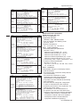
Level 3 menu
Level 5 menu
Note:
“Uncomp” means uncompensated value.
“PV % rnge” means % of output range.
1. Hold status
2. Hold fnc.
3. Hold type
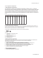
1. Logbook conf.
2. Logbook1
3. Logbook2
1. Date
2. Descriptor
3. Message
4. Write protect
5. Manufacturer
6. Dev id
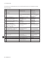
1. Powerup
2. Powerdwn
3. Defaults
4. Lg. Erased
5. Low range
6. High range
7. Hold on
8. Hold off
9. Error on
Error off
Temp. adj
Cell const
Air cal
Calibrate
Ref. temp
Temp. coef1
Matrix
Temp. coef2
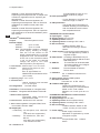
1. Param. specific
1. PV unit
2. Electrodes
3. CC nom
4. CC act
5. Pol. check
2. Temp. specific
1. Temp. sens
2. Temp. unit
3. Temp. compensation
1. Ref. Temp
2. TC1 type
3. TC2 type
4. Matrix table
4. Output function
1. mA func.
2. Burn func.
3. mA-table
5. User interface
1. Error prog.
Err.1···Err.13
2. Display
1. Auto. Ret
2. E5 lim.
3. E6 lim.
4. Percent
5. Fmt
6. USP
7. Passcodes
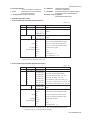
1. Model
2. Manufacturer
3. Distributor
4. Tag
5. Descriptor
6. Message
7. Date
8. Dev id
9. Write protect
Universal rev
Fld dev rev
Software rev
Hardware rev
Poll addr
Num req preams
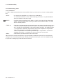
(Note): HART protocol DD files can be downloaded by following URL.
http://www.yokogawa.com/an/download/an-dl-fieldbus-001en.htm
IM 12D08B02-01E
Level 4 menu
1. Maintenance
2. Commissioning
3. Service
Note:
“Fmt” means displayed decimal point.
















![Model SC450G [Style: S2] Conductivity](http://vs1.manualzilla.com/store/data/005772923_1-d910951678550c5451dfdc47fd4527d0-150x150.png)