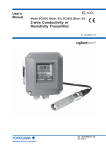
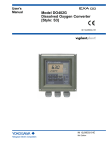
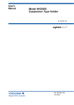
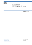
1
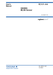
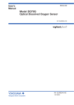
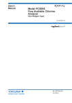
User’s Manual Dissolved Oxygen Metering System Model DO30G Dissolved Oxygen Sensor IM 12J5B3-01E R IM 12J5B3-01E 5th Edition i <INTRODUCTION> uIntroduction The DO30G Dissolved Oxygen Sensor bases its principle of measurement on the galvanic-cell method. The sensor is specifically suited for continuous measurement of oxygen dissolved in water. Topics and information that need your special attention in handling the product are given in the text of this manual along with cautionary notes, such as a warning or caution, depending on their importance. Strictly observe these items from the standpoint of safety and prevention of equipment damage. For a notation, such as a warning also indicated on the product, there is an alert mark in the manual. 1. Confirming the Specifications The standard specification DO30G dissolved oxygen sensor is used to build the dissolved oxygen metering system. The DO30G sensor cable has the prescribed length. The configuration of the crimp-on terminals are either pin-type, M4 ring-type or fork-type. Upon arrival of the purchased product, carefully unpack it and make sure the product is completely free from any damage that may have occurred during transport. Also check the model code indicated on the nameplate attached to the sensor cable to make sure that you received the correct sensor. For the meaning of the model code, refer to subsection 1.2.2 on page 1-3. Note: The model and suffix code of the sensor with standard specifications is as follows. DO30G-NN-50( : User specified alphanumeric) 2. Information Covered by This Manual This manual covers all of the information on handling the DO30G Dissolved Oxygen Sensor (Style B), such as instructions on installation, inspection, and maintenance and service. Note : When system components other than DO30G have to be mentioned, descriptions of the basic system assumes that the DO402G Dissolved Oxygen Converter is used. Refer to the instruction manual for information on the converter connecting holders with the DO30G and how to connect sensor cables. Note that the instruction manuals listed in the following table are for the associated equipment used with the EXA DO Dissolved Oxygen Metering System. Manuals for Associated Equipment Used with the EXA DO Dissolved Oxygen Metering Syatem Model Title of Manual Manual No. DO402G Dissolved Oxygen Converter IM 12J05D02-01E DO202 2-wire Dissolved Oxygen Transmitter IM 12J05C01-01E FLXA202/FLXA21 2-wire Liquid Analyzer IM 12A01A02-01E DO30G Dissolvecl Oxygen Sensor IM 12J5B3-01E PH8HG Guide Pipe IM 12B7M2-01E PB350G Angled Floating Ball Holder IM 19H1E1-01E DOX8HS Immersion Type Holder (Style B) IM 19H1D2-01E PH8PU1 Cleaning Pump/Tank IM 19C1E1-01E WTB10-DO Relay Terminal Box IM 12J05W02-01E Note: Only the basic system of basic components are listed on the front panel. Refer to respective instruction manual for information on recorders, annunciators and other instruments. Media No. IM 12J5B3-01E (CD) 5th Edition:Nov.2015 (YK) All Rights Reserved Copyright © 1996, Yokogawa Electric Corporation IM 12J5B3-01E 5th Edition : Nov.20,2015-00 ii <INTRODUCTION> For the safe use of this equipment u (1) About This Manual • This manual should be passed on the end user. • The contents of this manual are subject to change without prior notice. • The contents of this manual shall not be reproduced or copied, in part or in whole, without permission. • This manual explains the functions contained in this product, but does not warrant that they are suitable for the particular purpose of the user. • Every effort has been made to ensure accuracy in the preparation of this manual. However, when you realize mistaken expressions or omissions, please contact the nearest Yokogawa representative or sales office. • This manual does not cover the special specifications. This manual may be left unchanged on any change of specification, construction or parts when the change does not affect the functions or performance of the product. • If the product is not used in a manner specified in this manual, the safety of this product may be impaired. (2) Safety and Modification Precautions • Follow the safety precautions in this manual when using the product to ensure protection and safety of the human body, the product and the system containing the product. (3) The following safety symbols are used on the product as well as in this manual. The following safety symbols are used in this manual. CAUTION Identifies instructions that must be observed in order to avoid physical injury and electric shock or death of the operator. WARNING Identifies instructions that must be observed in order to prevent the software or hardware from being damaged or the system from becoming faulty. IMPORTANT Identifies important information required to understand operations or functions. TIP Identifies additional information. SEE ALSO Identifies a source to be referred to. IM 12J5B3-01E 5th Edition : Nov.20,2015-00 u iii <INTRODUCTION> After-sales Warranty l Do not modify the product. l During the warranty period, for repair under warranty carry or send the product to the local sales representative or service office. Yokogawa will replace or repair any damaged parts and return the product to you. l Before returning a product for repair under warranty, provide us with the model name and serial number and a description of the problem. Any diagrams or data explaining the problem would also be appreciated. l If we replace the product with a new one, we won't provide you with a repair report. l Yokogawa warrants the product for the period stated in the pre-purchase quotation. Yokogawa shall conduct defined warranty service based on its standard. When the customer site is located outside of the service area, a fee for dispatching the maintenance engineer will be charged to the customer. l In the following cases, customer will be charged repair fee regardless of warranty period. • Failure of components which are out of scope of warranty stated in instruction manual. • Failure caused by usage of software, hardware or auxiliary equipment, which Yokogawa did not supply. • Failure due to improper or insufficient maintenance by user. • Failure due to abuse, misuse or modification which Yokogawa does not authorize. • Failure due to power supply (voltage, frequency) being outside specifications or abnormal. • Failure caused by any usage out of scope of recommended usage. • Any damage from fire, earthquake, storms and floods, lightning, disturbances, riots, warfare, radiation and other natural changes. l Yokogawa does not warrant conformance with the specific application at the user site. Yokogawa will not bear direct/indirect responsibility for damage due to a specific application. l Yokogawa will not bear responsibility when user configures the product into systems or resells the product. l Maintenance service and supplying repair parts will be covered for five years after the production ends. For repair for this product, please contact the nearest sales office described in this instruction manual. IM 12J5B3-01E 5th Edition : Nov.20,2015-00 Blank Page v <CONTENTS> Dissolved Oxygen Metering System Model DO30G Dissolved Oxygen Sensor IM 12J5B3-01E 5th Edition CONTENTS uIntroduction.....................................................................................................i u For the safe use of this equipment..............................................................ii u After-sales Warranty ...................................................................................iii 1. General....................................................................................................... 1-1 1.1 Features.............................................................................................................. 1-1 1.2 Specifications..................................................................................................... 1-2 1.2.1 Standard Specifications...................................................................... 1-2 1.2.2 Model and Suffix Codes...................................................................... 1-3 1.2.3 External View and Dimensions........................................................... 1-4 2. Components and Their Functions........................................................... 2-1 3. Installing the Sensor and Connecting the Cable................................... 3-1 3.1 3.2 3.3 4. Preparing for Installation.................................................................................. 3-1 3.1.1 Removal of Parts for Transportation and Storage ............................. 3-1 3.1.2 Inspecting the Permeable Membrane................................................ 3-1 Installation.......................................................................................................... 3-2 3.2.1 Selecting the Measurement Point....................................................... 3-2 3.2.2 Selecting the Sensor Holder............................................................... 3-2 3.2.3 Asembling the Sensor in the Holder................................................... 3-4 Connecting the Sensor Cable........................................................................... 3-4 Maintenance............................................................................................... 4-1 4.1 4.2 4.3 Routine Inspection............................................................................................. 4-1 4.1.1 Inspecting the Permeable Membrane (Degree of Contamination).... 4-1 4.1.2 Checking of Membrane Assembly Locknut........................................ 4-1 Inspection If Failure Occurs.............................................................................. 4-2 4.2.1 Inspecting the Permeable-membrane Assembly (for Damage)......... 4-2 4.2.2 Checking of RTD in the Sensor.......................................................... 4-4 4.2.3 Judgment of Lead Electrode Fault...................................................... 4-4 Expendables, Spare Parts and Maintenance Parts........................................ 4-4 4.3.1 DOX8A Maintenance Parts (Expendables) Kit................................... 4-4 4.3.2 Parts That Should Be Kept on Hand................................................... 4-5 IM 12J5B3-01E 5th Edition : Nov.20,2015-00 vi <CONTENTS> Appendix 1. How to Remove the DO30G Membrane ProtectiveCap..........A-1 Customer Maintenance Parts List (DO30G)........................... CMPL 12J5B3-01E Customer Maintenance Parts List (DOX8A)....................... CMPL 12J05B03-12E Revision Record........................................................................................................i IM 12J5B3-01E 5th Edition : Nov.10,2015-00 1-1 <1. General> 1. General 1.1 Features • The sensor maintains stable characteristics over a prolonged period. It stabilizes in a initial time for electrolysis of approximately a half a day. The sensor has a structure less susceptible to the effects of deterioration in an electrolyte or contamination of the permeable membrane. Consequently, you can make precise measurements in a variety of processes. • You can choose the desired measurement point according to the nature of the solution being measured. You can submerse the DO30G Dissolved Oxygen Sensor to a depth of 3 m and then put it in regular use (the sensor can withstand a pressure of up to 100 kPa). The sensor can be assembled into a immersion type holder or a floating ball holder. The sensor, when assembled in the immersion type holder, allows automatic cleaning of the sensor with jetsprayed water or air at regular intervals. • The sensor is easy to service and very economical. Dissolved oxygen sensors usually deteriorate with time and ultimately come to the end of their service life. For the DO30G Dissolved Oxygen Sensor, only those parts whose service lives are relatively short, such as the membrane, may be replaced. Thus, running costs can be reduced. In addition, servicing and maintaining the sensor requires no special skills and is done quickly. Sensor cable Pin-type crimping terminals Fork-type crimping terminals Sensor unit M4 ring-type crimping terminals Permeable-membrane assembly Figure 1.1 F01.ai External View of the DO30G Dissolved Oxygen Sensor Note: The crimping terminals used on the sensor cables are either pin-type, M4 ring-type or fork-type depending on specifications. IM 12J5B3-01E 5th Edition : Nov.20,2015-00 1.2 1-2 <1. General> Specifications 1.2.1 Standard Specifications Object of Measurement: Concentration of oxygen dissolved in solution (water) Principle of Measurement: Galvanic-cell method Measurement Range: 0 to 20 ppm, 0 to 20 mg/L, or 0 to 100% (saturation) Note: The measurement range must be entered through the dissolved oxygen converter. Resistance Temperture Detector (RTD) : Pt1000 Construction: Sensor unit: Rigid PVC, Stainles steel O-ring:Nitrile rubber Permeable membrane: Fluoro-resin [FEP] Cable shielding: Heat-resistant flexible PVC Outlet of cable: Polycarbonate resin Sensor Cable: Length: 3 m, 5 m, 10 m, 15 m, or 20 m (specified when ordering) Crimping terminal configuration: Pin-type, M4 Ring-type or Fork-type (specified when ordering) Weight: Approx. 0.3 kg + 0.12 × N kg N: cable length (e.g. for cable length of 5 m, approx. 0.9 kg) Temperature of Solution Under Measurement (SUM): Flow rate of SUM: max. 0 to 40 °C No less than 20 cm/s (recommended to prevent the sensor from trapping bubbles that are the source of error in measurements) Pressure of SUM: Narmally: 0 to 30 kPa Maximum applicable:100 kPa [Characteristics] Repeatability: 0.1 mg/L or 3% FS, whichever is greater (including sensor) Temperature Compensation Error: Within ±3% FS (including sensor) for a ±5°C change in the range of 0 to 40°C Response Time: Within 2 minutes (90% response) (including sensor) IM 12J5B3-01E 5th Edition : Nov.20,2015-00 1-3 <1. General> 1.2.2 Model and Suffix Codes • DO Sensor Model Suffix Code DO30G •••••••••••••••••• -NN Membrane thickness -50 Cable length -03 -05 -10 -15 -20 Cable terminal -PN -FK -FL Option Code ••••••••••••••••••••• ••••••••••••••••••••• ••••••••••••••••••••• ••••••••••••••••••••• ••••••••••••••••••••• ••••••••••••••••••••• •••••••••••••••••••• •••••••••••••••••••• ••••••••••••••••••••• ••••••••••••••••••••• ••••••••••••••••••••• Description Dissolved Oxygen Sensor Always -NN 50 µm 3m 5m 10 m 15 m 20 m Pin terminal (*1) Fork terminal M4 ring terminal (*2) *1: Select pin terminal for DO402G, DO202, and FLXA202/FLXA21. When terminal box is used, select WTB10-DO3. *2: Used to connection to FLXA202/FLXA21.When terminal box is used, select WTB10-DO4. • DOX8A Parts Set for Maintenance Model DOX8A Sensor - Suffix Code •••••••••••••••••• -M *B Option Code Description •••••••••••••••••• Parts set for maintenance (for membrane thickness of 50 µm) •••••••••••••••••• For membrane replacing type sensor •••••••••••••••••• Style B A set of zero-adjusting reagent and maintenance parts <Contents> Zero adjusting reagent (sodium sulfite 500 g) 1 bottle Membrane assembly (for membrane thickness of 50 μm) 3 sets Electrolyte for sensor (50 mL) 1 bottle Syringe for replacing electrolyte 1 Polish for silver electrode (30 g) 1 bottle Polyethylene beaker (200 mL) 1 • DOX8W Calibration Set (optional) Model DOX8W Suffix Code *A Option Code Description •••••••••••••••••••• Calibration set This is necessary if the span calibration is to be done using a saturated dissolved oxygen solution. It is not necessary for air calibration. <Contents> Air pump, stirrer, stirring element, bubbler, clamp, beaker, and thermometer. Note: The calibration set can be used in common regardless of the type of holder. IM 12J5B3-01E 5th Edition : Nov.20,2015-00 1.2.3 1-4 <1. General> External View and Dimensions • Dissolved-oxygen sensor with pin terminals Unit: mm • Dissolved-oxygen sensor with fork terminals 11 12 14 13 15 16 11 12 14 13 15 16 Pin terminals Model and Suffix Codes DO30G - NN - 50 - 03 - PN DO30G - NN - 50 - 05 - PN DO30G - NN - 50 - 10 - PN DO30G - NN - 50 - 15 - PN DO30G - NN - 50 - 20 - PN Approx. 80 L 3 000 5 000 10 000 15 000 20 000 Weight (kg) Approx. 0.6 Approx. 0.8 Approx. 1.4 Approx. 2.0 Approx. 2.6 L 3 000 5 000 10 000 15 000 20 000 Weight (kg) Approx. 0.6 Approx. 0.8 Approx. 1.4 Approx. 2.0 Approx. 2.6 L 3 000 5 000 10 000 15 000 20 000 Weight (kg) Approx. 0.6 Approx. 0.8 Approx. 1.4 Approx. 2.0 Approx. 2.6 Fork terminals ø6.5 L • Dissolved-oxygen sensor with ring terminals 11 12 14 13 15 16 Model and Suffix Codes DO30G - NN - 50 - 03 - FK DO30G - NN - 50 - 05 - FK DO30G - NN - 50 - 10 - FK DO30G - NN - 50 - 15 - FK DO30G - NN - 50 - 20 - FK Ring terminals ø26 38.5 46 10 Terminal asign 108 ø30 ø36 13 15 11 12 14 16 IE RE T1 T2 Shield Liquid earth Model and Suffix Codes DO30G - NN - 50 - 03 - FL DO30G - NN - 50 - 05 - FL DO30G - NN - 50 - 10 - FL DO30G - NN - 50 - 15 - FL DO30G - NN - 50 - 20 - FL Note: Select pin terminasl for systems using the DO402G/FLXA21 dissolved oxygen converter. When using with FLXA202/FLXA21, M4 ring terminals is recommended. Figure 1.2 External View and Dimensions of DO30G Dissolved Oxygen Sensor IM 12J5B3-01E 5th Edition : Nov.20,2015-00 2. 2-1 <2. Components and Their Functions> Components and Their Functions Sensor cable Carries the detected signal to the dissolved oxygen converter. The desired cable length can be chosen from 3, 5, 10, 15, or 20m. You can choose either pin-type, M4 ring-type or fork-type terminals. Permeable-membrane assembly locknut Sensor unit Generates both an electrolytic current signal proportional to the amount of oxygen that passes through the permeable membrane and a temperature signal for compensation. O-ring Lead electrode Permeable-membrane assembly Silver electrode Temperature Detector Cutaway View of the Sensor Tip F03.ai Figure 2.1 Components and Their Functions of DO30G Dissolved Oxygen Sensor CAUTION Do not loosen the permeable-membrane assembly locknut except when replacing the assembly. IM 12J5B3-01E 5th Edition : Nov.20,2015-00 Blank Page 3-1 <3. Installing the Sensor and Connecting the Cable> 3. Installing the Sensor and Connecting the Cable 3.1 Preparing for Installation 3.1.1 Removal of Parts for Transportation and Storage A cap to prevent the membrane from being damaged when transporting the sensor is mounted at the tip of the DO30G Dissolved Oxygen Sensor. When installing the sensor, remove this protective cap (See Appendix 1.). 3.1.2 Inspecting the Permeable Membrane Any wrinkling or damage to the permeable membrane may lead to a failure to take normal measurements. Make sure the membrane is free from any wrinkling or damage. Also check that the membrane assembly locknut is not loose. If any wrinkling or damage is found, replace the membrane assembly with a new assembly unless such damage is slight. Permeable-membrane assembly locknut Make sure the locknut is not loose. Permeable membrane Make sure the membrane is free from any wrinkling or damage. F04.ai Figure 3.1 Inspection of Permeable-membrane Assembly IM 12J5B3-01E 5th Edition : Nov.20,2015-00 3.2 3-2 <3. Installing the Sensor and Connecting the Cable> Installation Normally, the DO30G Dissolved Oxygen Sensor is assembled into the PH8HG Guide Pipe, PB350G Angled Floating Ball Holder or DOX8HS Immersion Type Holder and submersed to the point best suited to obtain precise measurement results. This section explains how to select the measurement point and sensor holder. 3.2.1 Selecting the Measurement Point Normally, a location that meets the following requirements may be selected as the measurement point. l The measured value is representative among the values available for the solution under measurement (SUM). Avoid choosing a location where the solution is unevenly distributed, since heavy hunting may result in the measured value. Also, avoid locations where bubbles occur frequently. l The temperature and flowrate comply with the operating conditions required of the sensor and holder. Note that, if a measured solution running at a high flow rate contains particles of sand, the permeable membrane of the sensor may be damaged. Do not install the sensor at a depth greater than 3 m. 3.2.2 Selecting the Sensor Holder Each holder or fitting where the DO30G Dissolved Oxygen Sensor is assembled has the following characteristics. Choose a holder that suits the liquid to be measured and the measurement location. [PH8HG Guide Pipe] The holder is made of PVC resin and is 2 m long. The sensor is suspended down inside the cylindrical barrel of the holder. This pipe is conveniently suited for the measurement of a solution free from bubbles or pollutants. Stopper Sensor cable Mounting pipe Guide pipe (Outer diameter of 60.5 mm) Dissolved oxygen sensor F05.ai Figure 3.2 Suspension of Dissolved Oxygen Sensor Using PH8HG Guide Pipe IM 12J5B3-01E 5th Edition : Nov.20,2015-00 3-3 <3. Installing the Sensor and Connecting the Cable> [PB350G Angled Floating Ball Holder] The fitting is designed to contain the sensor in a sphere that floats on a liquid. This fitting is immune to large variations in the liquid level. Since the wet part is smooth and less susceptible to catching flocs, the sensor does not trap rubbish that mixes in with the SUM (Related description: See Subsection 3.2.3). The float is supported by an arm and does not move away from the measurement point even if the SUM is flowing. When using this holder the membrane damage detector function in the converter can be activated. Arm assembly Sensor cable Float Mounting bracket Fix the bracket to a nominal 50 A pipe (OD of 60.5 mm) or a horizontal surface (floor, the edge of a solution tank, etc.). Figure 3.3 F06.ai Suspension of Dissolved Oxygen Sensor Using PB350G Angled Floating Ball Holder [DOX8HS (Style B) Immersion Type Holder] The holder holds the sensor at an angle of 45°. Consequently, bubbles will not stick to the permeable membranne. Any pollutants in the SUM can be automatically cleaned off at regular intervals using a jet-spray water (air) cleaner. Cleaning-utility pipe Sensor cable Dissolved oxygen sensor Jet cleaner F07.ai Figure 3.4Suspension of Dissolved Oxygen Sensor Using DOX8HS Immersion Type Holder (with Jet Cleaner) IM 12J5B3-01E 5th Edition : Nov.20,2015-00 3.2.3 3-4 <3. Installing the Sensor and Connecting the Cable> Asembling the Sensor in the Holder For details on how to assmble the sensor in the holder or fitting, see the appropriate instruction manual for each holder or fitting. CAUTION Exercise care not to contaminate or wet the tip of the sensor cable when assembling the sensor. If you will not begin wiring the sensor cable immediately, take the protective measures necessary to prevent the assembly from being damaged. Sensor mounting in the case where flocs and other matter are contained in the SUM Stopper F07-1.ai The stopper projecting from the membrane assembly locknut serves to prevent the membrane from being in contact with the ground and thus being damaged. If there are flocs in the SUM, the stopper may become clogged. Thus, assemble the sensor to the holder so that the stopper is positioned downstream in the SUM. 3.3 Connecting the Sensor Cable The cable of the dissolved oxygen sensor must be connected to the terminals of the dissolved oxygen converter. For information on connections, refer to the following instruction manuals: DO402G Dissolved Oxygen Converter (IM 12J05D02-01E), the FLXA202/FLXA21,DO202 2-wire Transmitter instruction manual (IM 12A01A02-01E, IM 12J05C01-01E) or WTB10-DO Relay Terminal Box (IM 12J05W02-01E). Dissolved oxygen converter terminals for connection to sensor cable Jumper 21 *1: Liquid earth to detect membrane failure. This function is available when using PB350G/PB360G float type holder. Connect only when using this function. 17 IE T1 T2 SE RE S 13 11 12 14 15 16 13 11 12 14 15 16 (*1) Sensor cable F08.ai Figure 3.5 Connection of Sensor Cable Now the explanation on the installation and wiring is completed. For details on operation during startup or for regular operation after the entire measuring system is brought into operation, refer to the DO402G Dissolved Oxygen Converter instruction manual (IM 12J05D02-01E), the FLXA202/FLXA21, DO202 2-wire Transmitter instruction manual (IM 12A01A02-01E, IM 12J05C01-01E) The maintenance and service of the dissolved oxygen sensor is explained in Section 4 that follows. IM 12J5B3-01E 5th Edition : Nov.20,2015-00 4. 4-1 <4. Maintenance> Maintenance This section describes the inspection and maintenance procedure applicable to just the dissolved oxygen sensor alone. For comprehensive inspection and tuning of the measuring system, such as calibration, see the DO402G Dissolved Oxygen Converter instruction manual (IM 12J05D0201E), the FLXA202/FLXA21, DO202 2-wire Transmitter instruction manual (IM 12A01A02-01E, IM 12J05C01-01E). 4.1 Routine Inspection 4.1.1 Inspecting the Permeable Membrane (Degree of Contamination) An inspection (visual) of the permeable membrane must be made whenever the sensor is calibrated. Any dirt on the membrane will adversely affect your measurements. If the dirt is spread over the membrane, dip the membrane into clean water and gently wipe the dirt off with a soft cloth or lint-free paper. If the dirt will not come off easily, apply a neutral detergent to the membrane so it will be easier to remove the dirt. Clean the membrane with clean water. Finally, make sure the permeable-membrane assembly locknut is not loose. CAUTION Exercise care to avoid wrinkling or damaging the permeable membrane during inspection. Wrinkling and other damage prevent normal membrane operation. 4.1.2 Checking of Membrane Assembly Locknut At every calibration, check that the membrane assembly locknut is not loose. If it is, retighten it. In addition, if a phenomenon which is considered to be due to a change in the electrolyte quality (e.g., showing extremely low measured values) is observed after the locknut is retightened, replace the electrolyte according to the directions in Subsection 4.2.1. IM 12J5B3-01E 5th Edition : Nov.20,2015-00 4.2 4-2 <4. Maintenance> Inspection If Failure Occurs If the electrolyte and/or lead electrode within the sensor unit deteriorates and ultimately completes its service life, anomalies, such as the failure to make a span adjustment, will occur. This section deals especially with the inspection and service of the dissolved oxygen sensor needed if any anomaly is found in a detected signal. If you fail to pinpoint the cause of failure to a particular location, follow the instructions in Section 4.2.1 and subsequent sections in sequence. One or more of the following measures are necessary to remedy the failure. • Replacement of electrolyte/permeable-membrane assembly • Replacement of sensor unit 4.2.1 Inspecting the Permeable-membrane Assembly (for Damage) Note : When the membrane is used in the float holder, the converter membrane damage detector function can be used. This function generates an "E4" error message if the membrane is damaged. Check the permeable-membrane assembly for possible wrinkling or damage. Also, check that the permeable-membrane assembly locknut is not loose. If the locknut is securely tightened and the membrane is normal (no wrinkling or damage is found), proceed to the instruction procedure in Section 4.2.2. If the locknut is loosen or the membrane is wrinkled or damaged, replace the electrolyte and the permeable-membrane assembly (including the O-ring seal) as well. [Electrolyte/permeable-membrane assembly replacement procedure] When replacing the electrolyte and permeable-membrane assembly, you must provide a syringe and beaker that are used to replace the electrolyte and an abrasive and gauze to polish the silver electrodes. Provide these materials along with the spare electrolyte solution and assembly used in the replacement. CAUTION Precautions in Handling the Electrolyte The potassium-hydroxide electrolyte (KOH) is a highly alkaline solution containing potassium hydroxide as the major constituent. Exercise extreme care to protect your body from contact with the solution and to prevent the solution from getting into your eyes. Should your skin or eyes become exposed to the solution, immediately wash the exposed area with clean water. If the solution gets in your eyes, consult an eye doctor after flushing them with water. The electrolyte is a colorless corrosive and, therefore, there is the risk of its being mishandled. Never leave any residual solution in the syringe. (1) After having removed the dissolved oxygen sensor from the holder, clean dirt off the wet part. (2) Loosen the locknut and remove the permeable-membrane assembly. Also, remove the O-ring. IM 12J5B3-01E 5th Edition : Nov.20,2015-00 4-3 <4. Maintenance> (3) Completely drain the electrolyte within the sensor unit. Tilt the sensor tip downward and then use the syringe to force air into the inlet for refilling the electrolyte. Position the beaker so it will catch any of the electrolyte that drains through the gaps around the silver electrode. Inlet for refilling electrolyte Needle (syringe needle) Sensor unit Insert the syringe needle into the inlet for refilling electrolyte and force air inside. Place a beaker underneath to catch the draining electrolyte. Silver electrode Syringe F09.ai Figure 4.1 Draining the Electrolyte (4) Removing dirt, deposits, or stains from the surface of the silver electrode. Lay the sensor horizontally. Apply alumina as an abrasive to moistened gauze and polish the surface of the silver electrode to remove any stains from the surface. Do not polish excessively. A mirror-finished surface of the electrode or any damage to the epoxy materials around the electrode may affect the performance of the sensor. After polishing, wipe the alumina off the electrode completely. (5) Make sure the sealed surfaces are free from dust. Install a new O-ring. (6) Inject 8 ml of electrolyte into the sensor body with the syringe (see Figure 4.2). Note: Always use an electrolyte prepared by Yokogawa for exclusive use with the DO30G. First, fill the sensor with the electrolyte (approx. 9 ml) and then remove approximately 1 ml so that a layer of air is present inside the sensor body. (7) Install the permeable-membrane assembly. It is strictly not possible to allow a layer of air to form between the membrane and the silver electrode. To prevent such a layer from forming, first apply a drop of electrolyte to the surface of the silver electrode. Lightly press the permeable-membrane assembly so that the O-ring touches the groove on the inside. Tighten the locknut fully without letting the assembly turn. Surface of the silver electrode Apply a drop of electrolyte when installing the permeable-membrane assembly. Fill with electrolyte and then remove approximately 1 mL. Syringe Inlet for injecting electrolyte O-ring F10.ai Figure 4.2 Injecting the Electrolyte All these steps complete the inspection procedure for the permeable-membrane assembly. By way of precaution, make sure the membrane is free from wrinkling. Note that a stable detection signal is not possible right after refilling with the electrolyte. Make a zero or span adjustment approximately a half a day or longer after refilling. It may indicate a minus value for about 10 minutes zero adjustment. IM 12J5B3-01E 5th Edition : Nov.20,2015-00 4.2.2 4-4 <4. Maintenance> Checking of RTD in the Sensor The resistance temperature detector (RTD) incorporated in the DO30G sensor is a Pt1000Ω RTD. This Pt1000Ω RTD indicates a resistance value of about 1097Ω at 25°C. Check the RTD by measuring the resistance value between conductors 11 (T1) and 12 (T2). If the resistance value differs greatly from the above value, the sensor must be replaced. 4.2.3 Judgment of Lead Electrode Fault If no failure is found in the checks in Subsections 4.2.1 and 4.2.2, the cause of the problem may be the end of the service life of the lead electrode or a loose connection of the conductors. In either case, the sensor must be replaced. [Service Life of Lead Electrode] The lead electrode mounted in the sensor body gradually erodes due to battery action. When span adjustment becomes impossible for a sensor which has been used in succession over a long period even if the electrolyte/membrane assembly has been replaced, it shows that the lead electrode has reached the end of its service life. The service life of the lead electrode varies with the temperature of the SUM or the amount of dissolved oxygen. Under general operating conditions, it should be approximately three to four years. 4.3 Expendables, Spare Parts and Maintenance Parts This section presents the general information on spare parts that the manufacturer recommends you to provide and on materials that are used in maintenance and service. When procuring these parts or materials, also refer to the Customer Maintenance Parts List (CMPL) at the end of this manual. 4.3.1 DOX8A Maintenance Parts (Expendables) Kit The DOX8A Maintenance Parts Kit contains, as a set, spare parts for the expendables that need to be replaced within one year after the start of use of the DO30G Dissolved Oxygen Sensor, the materials that are used during replacement, and a reagent that is used to prepare the calibration solution for zero adjustment. Note: There are two different DOX8A Maintenance Parts Kit available: style A and style B. Be sure to use a style B membrane assembly (membrane thickness: 50 μm) for a EXA DO dissolved oxygen metering system. IM 12J5B3-01E 5th Edition : Nov.20,2015-00 4-5 <4. Maintenance> Table 4.1 Items Contained in the DOX8A Maintenance Parts Kit Item Part No. Qty Remarks 50 mL Must be replaced periodically, either once every 6 to 8 months or if a span adjustment is not possible. Eight to 9 ml are consumed with each replacement. K9171HM 3 sets Normally, these parts must be replaced at the same time that the sensor is refilled with electrolyte. If the sensor is used in a slurry solution, these parts may require replacement more often due to abrasion or damage. Reagent for preparing calibration solution (for zero adjustment) sodium sulfite (Na2SO3) L9920BR 500 g Calibration must be carried out at a predetermined interval (the frequency of calibration varies depending on the operating conditions). Calibration must also be performed when, for example, the electrolyte is replaced. Approximately 50 grams of the reagent is needed to prepare 1 liter of the calibration solution for zero adjustment. 5-mL syringe (without needle) Needle L9827NH L9827NG 1 1 Used when replacing the electrolyte. 200-mL beaker L9825AF 1 Used when calibration is carried out or when the electrolyte is replaced. 30 g Polish the silver electrode every time the permeable membrane assembly is replaced. Each polishing usually needs only a very small amount of alumina (about 0.5 g). Electrolyte K9171DN Permeable-membrane assembly/O-ring Abrasive for silver electrode (alumina) 4.3.2 K9088PE Parts That Should Be Kept on Hand Even parts with a long service life are not completely free from possible failure. It is recommended that users have on hand spare parts for those parts which, if they become defective, will make it impossible to continue measurement. [Membrane Assembly Locknut (part number: K9171CH)] It is recommended that users have spare parts for the locknut on hand in preparation for possible failure. [Spare Sensor Assembly] If the sensor assembly remains unused over a prolonged period, the electrolyte may change in quality or some anomalies may occur in the permeable membrane. Consequently, these materials must be replaced with new ones before you can use the sensor. Although it is desirable that users always try to avoid storing the sensor assembly for long periods, the manufacturer recommends that users keep a spare part on hand for the sensor assembly in anticipation of an unexpected failure. Do not store the sensor with the electrolyte removed. Otherwise, any residual electrolyte may become concentrated, harming the lead electrode or other mechanisms. If the sensor must be stored with the electrolyte removed, completely clean the inside of the sensor with clean water (repeat injecting and draining the water several times) before it is stored. Note: If the sensor is stored without the electrolyte, repeat injecting and draining the electrolyte several times before you reuse it. IM 12J5B3-01E 5th Edition : Nov.20,2015-00 Blank Page A-1 <Appendix 1.> Appendix 1. How to Remove the DO30G Membrane ProtectiveCap CAUTION A black rubber cap is attached to the tip of the DO30G to protect the membrane. Pulling off the cap forcefully causes a negative pressure inside the protective cap, because the protective cap sticks to the DO30G, and may stretch the membrane or damage it. Furthermore, removing the cap by twisting it may loosen the membrane assembly and affect the measurement results. Please read the following notes and removal procedure in advance in order to prevent damage and loosening of the membrane assembly from occurring. 1. Prohibited actions Prohibited action 2 Prohibited action 1 No good No good Figure 1Do not pull off the cap forcefully Figure 2Do not pull off the cap twisting the cap counterclockwise. 2. How to Remove Protective Cap When taking out of the package, a black rubber cap is attached the DO30G shown below. DO30G Protective cap Figure 3Condition after taking out of the package IM 12J5B3-01E 5th Edition : Nov.20,2015-00 A-2 <Appendix 1.> When using a stick or the like. When an appropriate stick or the like is not available. (1) As shown in the figure 4, insert a stick or the like between the DO30G and protective cap. Be careful not to damage the DO30G main body. (1) Hold the protective cap while holding the DO30G as shown in the figure 7. Stick or the like Protective with a diameter of cap 0.1 to 0.2 mm Figure 4Insert a stick or the like between the DO30G (2) Push it in so that enough air space is created between the DO30G and protective cap. Push it beneath the protective cap and up to the tip of the sensor. Figure 5Push a stick or the like beneath the protective cap to create air space. Protective cap Figure 7Hold the DO30G and protective cap. (2) Remove the protective cap by turning it clockwise slowly. Turn it clockwise slowly. Figure 8Remove the protective cap by turning it clockwise slowly Maintain the space. DO30G tip Figure 6Pull off the protective cap while maintaining the air space. IM 12J5B3-01E 5th Edition : Nov.20,2015-00 Customer Maintenance Parts List Dissolved Oxygen Metering System DO30G Dissolved Oxygen Sensor 1 3 2 Model DO30G Membrane thickness Cable terminal 1 2 3 1 1 K9171CH K9171HM Qty Description Dissolved oxygen sensor (Refer to table of below "Model & Code") Box nut assembly Membrane/O-ring Suffix Code Option Code Description …………………… …………………… Dissolved oxygen sensor Cable length Item Part No. 1 - -NN …………………… Always - NN -50 …………………… 50 µm -03 -05 -10 -15 -20 …………………… …………………… …………………… …………………… …………………… -PN …………………… -FK …………………… -FL …………………… 3 m 5 m 10 m 15 m 20 m Pin terminal Fork terminal M4 ring terminal All Rights Reserved, Copyright © 1996, Yokogawa Electric Corporation. Subject to change without notice. CMPL 12J5B3-01E 3rd Edition : Oct,2010 Customer Maintenance Parts List Model DOX8A-M*B Accessory for EXA DO 2 4 1 3 5 6 7 9 10 8 200 150 100 50 Item Part No. Qty Description 1 L9825AF 1 200 ml Beaker 2 L9920BR 1 Reagent (for zero calibration) 3 K9088PE 1 Polishing Powder 4 K9171HK 1 Spare Parts & Service Tool 5 K9171DN 1 6 K9171HM 3 7 G9303NM 1 8 K9171CS 1 9 L9827NG 1 Needle 10 L9827NH 1 5 ml Sylinge Electrolyte Membrane / O-Ring Set O-Ring Membrane Assembly (50 mm) All Rights Reserved, Copyright © 1996, Yokogawa Electric Corporation. Subject to change without notice. CMPL 12J05B03-12E 2nd Edition : Feb. 2006 (YK) i Revision Record Title : Model DO30G Dissolved Oxygen Sensor Manual No. : IM 12J5B3-01E Nov. 2015/5th Edition Added FLXA202 P i, P1-3, P1-4, P3-4, P4-1. Supplement of 4th Edition P1-2, Some revision of construction for sec. 1.2.1. P4-3, Some revision of Section 4.2.1 Inspecting the Permeable-membrane Assembly. P 4-5, Some revision of Table 4.1. Apr. 2011/4th Edition Over all revised. P. i, FLXA21 and DO202 manual no. added to documnents to be refered. P. 1-1, Stabilized time in a initial time for electrolysis modified. M4 ring terminal added to Figure 1.1. P. 1-2, M4 ring-type terminal added to specifications. P. 1-3, FLXA21 added to MS-code. P. 1-4, M4 ring terminal added to Figure 1.2. P. 2-1, M4 ring terminal added to Figure 2.1. P. 3-1, Addition of Appendix 1 to be refered for section 3.1.1 "Removal of Parts for Transportation and Storage." P. 3-4, FLXA21 and DO202 manual no. added to section 3.3 "Connecting the Sensor Cable." P. 4-1, FLXA21 and DO202 manual no. added to section 4 "Maintenance." P. 4-3, Stabilized time in a initial time for electrolysis modified. Appendix 1 "How to Remove the DO30G Membrane Protective Cap" added to end of this manual. CMPL 12J5B3-01E revised to 3rd edition (M4 ring terminal added). Mar. 2010/3rd Edition MS-code of DOX8A, DOX8W added to Section 1.2.2. CMPL 12J05B03-12E(2) added for DOX8A. May 2007/2nd Edition Fully revised. Nov. 1996/1st Edition Newly published. n If you want to have more information about Yokogawa products, you can visit Yokogawa’s home page at the following web site. Home page: http://www.yokogawa.com/an IM 12J5B3-01E 5th Edition : Nov.20,2015-00 Blank Page