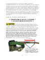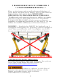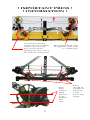
1
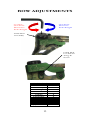
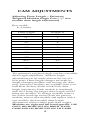
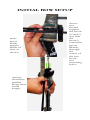
2012 Owner’s Manual Members of the ATA 817 Maxwell Avenue • Evansville, IN 47711 800-694-9494 • fax 812-467-1245 www.BearArcheryProducts.com Contents Important Bow Information 3-5 Archery Safety & Warnings 6-7 Bow Diagrams 8-9 Care & Maintenance 10-11 Bow/Cam Adjustments 12-28 Initial Bow Setup 29-33 Arrow Selection Information Warranties 34 35-36 Record important bow information here and keep for future reference. Model:__________________________ Weight Range:___________________ Draw Length:____________________ String Length:___________________ Cable Length:___________________ Purchased From:_________________ Date Purchased:__________________ Serial Number:___________________ 2 Congratulations! Your new Bear Archery compound bow is the finest available. It has been engineered for accuracy, long life, and built with quality and pride. No other bow delivers a higher performance to value ratio than a Bear. We know how much you are going to enjoy your new bow. For this reason, we ask you read the Care and Maintenance section carefully to learn how easy it is to maintain the quality, performance, and level of satisfaction you expect from a Bear Archery product. ENJOY YOUR NEW BOW! ! IMPORTANT LIMB ! ! INFORMATION ! Your new Bear Archery bow uses the latest technology in limb design. This creates a limb capable of storing optimal amounts of energy unlike any other bow in the industry. For that reason, the use of limb mounted accessories such as vibration dampeners must be restricted. These particular accessories MUST NOT BE mounted more than 2 inches from the limb pockets. Mounting limb accessories more than 2 inches away from the pockets, particularly clamping type accessories, can potentially damage the limbs and void the warranty. See the illustration below. 2” MAX Limb mounted accessories CAN BE MOUNTED IN THIS REGION OF THE LIMB ONLY. 3 ! IMPORTANT PRESS ! ! INFORMATION ! Due to the innovative and advanced design of your Bear Archery bow limbs, it is of the utmost importance that your bow ONLY BE PRESSED IN PROPER BOW PRESSES. Traditional style presses that use rollers to apply pressure only to the mid section of the limbs CANNOT BE USED. Only presses that are capable of applying pressure to the last 2” of the limbs should be utilized, as illustrated below !NOTE! – Limb bolts MUST be backed out 4 complete turns prior to pressing a bow equipped with flare quad limbs and 3 complete turns for bows equipped with max pre-load quad limbs. DO NOT USE THIS STYLE PRESS ARMS APPROVED BOW PRESSES: For the most up to date and accurate list, please visit your local Bear Archery dealer or www.BearArcheryProducts.com Failure to adhere to this list of presses can result in immediate failure of the limbs, possible injury and void the manufacturer’s warranty. 4 ! IMPORTANT PRESS ! ! INFORMATION ! Certain bow models require the use of fixed stops to prevent the press forces from pushing the bow out of the bottom of the press Bow press MUST only be applied to the outer 2” of limb tips. Press must ONLY apply pressure to the limbs in this area. 5 Press should be capable of adjusting to the riser’s full length ! SAFETY FIRST ! Before using this equipment, read and follow these manufacturer’s instructions carefully. If you have any questions, contact the manufacturer or a qualified dealer. Dry-firing a bow severely reduces the life expectancy of the bow and may cause immediate damage to the bow resulting in injury to yourself or others. Never dry-fire your bow! Never pull back and release the bowstring without an arrow attached to the string. Your bow is designed to transfer energy to a properly weighted arrow. Shooting underweight arrows has the same effect as dry-firing a bow and may cause serious injury. Use the proper arrow for you and your bow. If you are unsure about your arrow choice, contact your local Bear Archery dealer or an arrow manufacturer. Do not use wooden or fiberglass arrows. They are not designed for use with this compound bow and may cause serious injury. Use the proper arrow for you and your bow. If you are unsure about your arrow choice, contact your archery dealer or an arrow manufacturer. Inspect your arrows and nocks regularly. Immediately discard any dented, split, splintered or otherwise damaged arrows and replace cracked or broken nocks. Do not draw your bow beyond its maximum draw length as damage to the limbs, cables and strings could occur. The use of safety glasses is recommended with any archery product. 6 ! SAFETY FIRST ! Targets and Hunting Safety Be sure of your target. Bowhunters often wear camouflage and are difficult to identify. Never aim at anything you don’t intend to shoot. Never point or aim a drawn bow at another person. Never draw or shoot when anyone is between you and your target. Never shoot at a target or object unless you are sure that it can stop your arrows. Make sure the area behind and around your target is clear. Before shooting, be sure that no part of the bow will strike any tree branches or other obstacles. Never shoot arrows straight up in the air or in any direction where you might destroy property or endanger life. Pre-shooting checklist Are these items in good condition? Properly installed? In working order? ___ ___ ___ ___ ___ Cables String String Serving Loop/Nock set Cable Slide ___ ___ ___ ___ ___ 7 Sight Arrow Rest Arrow Nocks Arrow Shafts Set Screws BOW DIAGRAMS Understanding your bow and its component parts will add to your archery enjoyment. Although bows differ in performance and features, these photos represent the components available in various combinations on most models. Being familiar with this information will help you with the instructions throughout this manual. Also, you can refer to these photos when ordering parts or making technical inquiries. Weighted Axle Dampeners Cable with Split Yoke Flare Quad Limbs Arc String Suppressor Limb Bolt Assembly Cable guard Continuous String Cable Slide Arrow Rest Mounting Holes 8 BOW DIAGRAMS Idler Wheel Limb Pocket Riser Roller Cable Guard Sight Window and Mounting Holes Grip Stabilizer Mounting Hole Max Pre-Load Quad Limbs Cam 9 CARE AND MAINTENANCE With proper care and a minimum amount of routine maintenance, your bow will be kept in top condition. However, it is still important to carefully inspect your bow on a regular basis. Cleaning Your bow should be kept clean of dust, mud and grime. Use a damp soft cotton cloth to remove dirt and moisture. Do not use solvents such as acetone or mineral spirits as they may ruin the finish. Storage and Transportation Avoid exposing your bow to temperatures over 150 degrees. Excessive heat may damage your bow. Do not leave your bow unprotected in your vehicle on a hot sunny day or store in a hot attic or other hot enclosed area. Clean your bow thoroughly after each use. Never put your bow away wet or store it in a damp place. Lightly oil all steel parts (axles, mounting screws) to prevent rust. You can relax the limbs if storing for more than a year. Follow the instructions under Peak Draw Weight Adjustment in the bow adjustment section. Bow Presses Use only “double-pull” type APPROVED bow presses. A “double-pull” bow press draws your bow down at two points on the riser. Older style “single-pull” bow presses that contact the bow only in the grip area can result in bent or broken risers. To reduce unnecessary stress on the riser, back off the limb bolts 2-3 turns before placing in a press. See page 4 and/or www.BearArcheryProducts.com for additional bow press information. 10 CARE AND MAINTENANCE Lubrication Your Bear Archery compound bow requires very little lubrication. Wipe the cable guard periodically with a dry cloth to keep the cable slide running smoothly and free of dust. Cam and idler wheel bearings do not require lubrication. If other lubrication is necessary, use white lithium grease or Teflon lubricants. Avoid excessive lubrication of any item, as this can attract dirt. On hunting bows, avoid lubricants with obvious odors. String and Synthetic Cable Maintenance Regularly apply a high quality bowstring wax to your string and synthetic cable system. Regular waxing protects your cables and strings from abrasion, wear and separation. Smear the wax into position. Then, rub it gently with your fingers or a soft piece of leather to work the wax into the strands. Replace frayed or worn bowstrings and cables immediately. •Bear Archery strongly recommends replacing the bowstring and cable annually. Please visit your local Bear Archery dealer for assistance. 11 BOW ADJUSTMENTS Peak Draw Weight Adjustment Bear Archery bows have a 10 pound peak weight adjustment range. If your bow is equipped with limb bolt lock downs, make sure these screws (small single button head screw attached to riser through “tang” protruding from underneath the limb pocket) are loosened before making any weight adjustments. Using a 7/32” hex wrench for bows with a 3/816 limb bolt, and a 3/16” hex wrench for bows with a 5/16-18 limb bolt, turn the limb bolts clockwise to increase peak weight and counterclockwise to reduce peak weight. Bow weight will increase or decrease approximately two to four pounds per turn. IMPORTANT Both limb bolts must be adjusted equally. Likewise, do not turn one limb bolt more than two turns ahead of the other when making adjustments. Finally, limb bolts must never be backed out more than 3 full turns on bows that are equipped with max preload quad limbs. Do not back out the limb bolts more that 4 full turns for bows equipped with flare quad limbs. Bows with limb bolt lockdowns: After all tuning adjustments have been made; engage the limb bolt lock down screws. Screws should be snug against the limb pocket “tang”. 12 BOW ADJUSTMENTS CounterClockwise Decreases Peak Weight Clockwise Increases Peak Weight Limb Bolt Assembly Limb Bolt Lockdown Tang & Screw Limb Bolt Adjustment Bow Max Turns Anarchy 3 Carnage 3 Mauler 3 Legion 3 Encounter 3 Outbreak 8 Siren 3 Homewrecker 3 Apprentice 2 6 13 CAM ADJUSTMENTS Adjusting Draw Length – Perimeter Weighted Modular Single Cam ( ½” size module draw length adjustment) Bow model: • Anarchy Draw length 31.5” 31” 30.5” 30” 29.5” 29” 28.5” 28” 27.5” 27” 26.5” 26” 25.5” 25” Module # 9.5 9 8.5 8 7.5 7 6.5 6 5.5 5 4.5 4 3.5 3 The perimeter weighted single cam has a modular draw length adjustment. All draw length adjustments can be made without the use of a bow press. Draw length changes are made by simply changing modules and moving the draw stop. Accessory modules are available from your local Bear Archery dealer in half-inch draw length increments. Each module is numbered, with #9.5 being the longest draw length and #3 being the shortest. To change modules remove the socket head cap screws from the present module, remove that module and replace with a new module. Such module draw length adjustments will not affect peak draw weight. Modules are right and left hand specific. USE ONLY RH MODULES ON RIGHT HAND CAMS AND LH MODULES ON LH CAMS! 14 Setting the TWO SIDED DRAW STOP When a module is changed, the draw stop must also be moved to the corresponding setting marked on the cam. The Anarchy has a new two sided draw stop system. This system consists of a draw stop that utilizes two mounting bosses to achieve different draw stop settings. Each draw stop is marked with a 1 on one side and a ½ on the other side. These marks are used to match the stop with the desired module. If a whole number module is to be used, the draw stop must have the 1 facing out when mounted, if a half number module is to be used, the draw stop must have the ½ facing out when mounted. There is only one mounting hole in the cam for each whole and half number module set. For example, when setting a bow up with either a number 6 or a number 6 ½ module, the stop will mount in the #6 hole for both settings, but on the 6 module, the stop will read “1” facing out, and on the 6 ½ module, the stop will read “1/2” facing out. The stop will only mount in one orientation for each setting. DO NOT force the stop into the mounting hole; it will slip into the hole when the correct orientation is achieved. Example Shown: Refer to the images on the next page for additional reference. 15 TWO SIDED DRAW STOP EXAMPLES #6 Module Draw Stop Position for # 6 Module #6.5 Module Draw Stop Position for #6.5 Module 16 CAM ADJUSTMENTS Module number engraved in module Module Draw Stop Back View Draw Stop Screw Perimeter Weight Module Mounting Screws 3, 3.5 Draw Position #9 and #9.5 Draw Stop Position 4, 4.5 Draw Position 5, 5.5 Draw Position #8 and #8.5 Draw Stop Position 6, 6.5 Draw Position 7, 7.5 Draw Position Front View 17 CAM ADJUSTMENTS Adjusting Draw Length – Perimeter Weighted Modular Single Cam ( ½” size module draw length adjustment) Bow model: • Carnage Draw length 30.5” 30” 29.5” 29” 28.5” 28” 27.5” 27” 26.5” 26” 25.5” Module # 10 9.5 9 8.5 8 7.5 7 6.5 6 5.5 5 The perimeter weighted single cam has a modular draw length adjustment. All draw length adjustments can be made without the use of a bow press. Draw length changes are made by simply changing modules and moving the draw stop. Accessory modules are available from your local Bear Archery dealer in half-inch draw length increments. Each module is numbered, with #10 being the longest draw length and #5 being the shortest. To change modules remove the socket head cap screws from the present module, remove that module and replace with a new module. Such module draw length adjustments will not affect peak draw weight. Modules are right and left hand specific. USE ONLY RH MODULES ON RIGHT HAND CAMS AND LH MODULES ON LH CAMS! When a module is changed, the draw stop must also be moved to the corresponding setting marked on the cam. Refer to the images on the next page for additional reference. 18 CAM ADJUSTMENTS Draw Stop Module Module number engraved in module Back View Perimeter Weight Module Mounting Screws Draw stop increments must match module number Draw Stop Screw 5.5 Draw Position 6.5 Draw Position 9.5 Draw Position 8.5 Draw Position Front View 19 7.5 Draw Position CAM ADJUSTMENTS Adjusting Draw Length – Perimeter Weighted Modular Single Cam (1” size module draw length adjustment) Bow model: • Mauler • Attack • Assault The perimeter weighted single cam has a modular draw length adjustment. Most draw length adjustments can be made without the use of a bow press. Draw length changes are made by simply changing modules and moving the draw stop. Accessory modules are available from your local Bear Archery dealer in one-inch draw length increments. Each module is numbered, with #10 being the longest draw length and #5 being the shortest. To change modules remove the socket head cap screws from the present module, remove that module and replace with a new module. Such module draw length adjustments will not affect peak draw weight. Modules are right and left hand specific. USE ONLY RH MODULES ON RIGHT HAND CAMS AND LH MODULES ON LH CAMS! When a module is changed, the draw stop must also be moved to the corresponding setting marked on the cam. Additionally, fine draw length adjustments of ½ inch can be made by removing the bowstring from the standard “dot” string post and reattaching it to either the “+” or “-“ string posts on the cam. Moving the string to the “+” post will increase draw length by ½” and moving the string to the “-“ post will decrease draw length by ½”. To make such adjustments, it is first necessary to remove tension from the harness system of the bow by compressing the bow in a bow press. A fixed or portable bow press must be used! Under NO circumstances can this relaxing of the harness system be accomplished by simply backing out limb bolts. Refer to the images on the next page for additional reference. 20 CAM ADJUSTMENTS Draw Stop Standard “dot” Post “+” Post Module Module number engraved in module Back View Perimeter Weight Module Mounting Screws Draw Stop Screw Standard “dot” Post “-“ Post Front View 21 Draw stop increments must match module number CAM ADJUSTMENTS Adjusting Draw Length – Rotating Module System Bow models: • Legion • Encounter • Siren Module # Setting 5 5.5 6 6.5 7 7.5 8 8.5 9 9.5 10 Legion DL 26" 26.5" 27" 27.5" 28" 28.5" 29" 29.5" 30" 30.5" 31" Encounter DL 27" 27.5" 28" 28.5" 29" 29.5" 30" 30.5" 31" 31.5" 32" Siren DL 22" 22.5" 23" 23.5" 24" 24.5" 25" 25.5" 26" 26.5" 27" The rotating module cam system allows the bow to be adjusted to all of its draw length positions without the use of separate individual modules and does not require a bow press for draw length adjustments at 1/2” increments. Draw length changes are made by first removing the socket head cap screws that secure the rotating module unit. Next, rotate the module until the desired draw length tick mark is lined up with the module tick mark, and reinstall the screws in the corresponding holes. The cam itself is marked with draw length increments where #10 is the longest setting and #5 is the shortest. Such draw length adjustments will not affect peak draw weight. When the rotating module unit is repositioned to adjust draw length, the draw stop must also be moved to the corresponding setting marked on the cam. 22 CAM ADJUSTMENTS Cable Post String Post Draw stop Rotating Module Cam Draw length increments engraved in cam Module Tick Mark Back View Perimeter weight Rotating Module Screws String Post Draw stop screws Draw stop increments MUST MATCH draw length setting Front View 23 CAM ADJUSTMENTS Siren Rotating Module Cam Back View Bolt on third track Thread Locked Screws Cam The Siren rotating module cam is equipped with a bolt on third track system. DO NOT remove the third track for any reason. The screws holding this track on have been set with a thread binding agent and should never be removed. The third track is not changed during any adjustment of this cam. 24 CAM ADJUSTMENTS Adjusting Draw Length – Inner Cam System Bow model: • Strike • Charge • Home Wrecker The inner cam system allows the bow to be adjusted to all of its draw length positions without the use of separate individual modules and does not require a bow press for draw length adjustments at 1” increments. Draw length changes are made by first removing the socket head cap screw that secures the inner cam unit. Next, move the inner cam unit to the desired draw length and reinstall the screw in the corresponding hole. The cam itself is marked with draw length increments where #10 is the longest setting and #6 is the shortest. Such draw length adjustments will not affect peak draw weight. When the inner cam unit is repositioned to adjust draw length, the draw stop must also be moved to the corresponding setting marked on the cam. Draw stop must be positioned so that the side marked “OUT” faces out. Additionally, fine draw length adjustments of ½ inch can be made by removing the bowstring from the standard “dot” string post and reattaching it to either the “+” or “-“ string posts on the cam. Moving the string to the “+” post will increase draw length by ½” and moving the string to the “-“ post will decrease draw length by ½”. To make such adjustments, it is first necessary to remove tension from the harness system of the bow by compressing the bow in a bow press. A fixed or portable bow press must be used! Under NO circumstances can this relaxing of the harness system be accomplished by simply backing out limb bolts. Refer to the images on the next page for additional reference. 25 CAM ADJUSTMENTS “+” post Standard “dot” post Draw stop MUST FACE OUT Inner cam screw Cam Inner cam unit Draw length increments engraved in cam Back View Perimeter weight Standard “dot” post “-“ post Draw stop screws Front View 26 Draw stop increments MUST MATCH draw length setting CAM ADJUSTMENTS Adjusting Draw Length – Rotating Modular Cam System with MultiDraw Bow model: • Apprentice 2 • Outbreak The adjustable multidraw cam equipped bow can be configured to provide a draw length from 15” to 27” in 1” intervals. No bow press is required to adjust the multidraw cam system. To adjust the draw length, first remove the socket head cap screw located in the rotating module. Next rotate the module to the desired draw length and reinstall the screw in the corresponding hole. It may be necessary to pull the cable away from the module to provide clearance for the module to rotate, see the picture below. Next perform the same operation on the opposite cam. Be sure that both the top and bottom cams are set to the same draw length position. The adjustable cam operates on a sliding poundage scale where an increase in draw length also provides an increase in peak draw weight. This allows the bow to grow with the archer. Cam Module Mounting Screw Right or left hand designation Back View Draw Length printed on module 27 Front View OUTBREAK Draw Weight vs. Draw Length Chart Rotating Module Module Mounting Screws Cam Cable Post String Post Draw Length [in] vs Draw Weight [lbs] Limb Bolt Bottomed Limb Bolt Fully Backed Out Draw Length 60 lb 50 lb 60 lb 50 lb Outbreak Outbreak Apprentice 2 Apprentice 2 Apprentice 2 Apprentice 2 15 39.5-43.5 30-34 21-25 14.5-18.5 16 39.5-43.5 30-34 28-32 21-25 14.5-18.5 16-20 17 39.5-43.5 30-34 28.5-32.5 21-25 14.5-18.5 16-20 18 40-44 31.5-35.5 32.5-36.5 23-27 16-20 19-23 19 43.5-47.5 34-38 37-41 24.5-28.5 17.5-21.5 21.5-25.5 20 45.5-49.5 36.5-40.5 41-45 26-30 20-24 24.5-28.5 21 48-52 39.5-43.5 45-49 28-32 21.5-25.5 27-31 22 50-54 40.5-44.5 49.5-53.5 29.5-33.5 23-27 30-34 23 51.5-55.5 42.5-46.5 53-57 31-35 24.5-28.5 32.5-36.5 24 53-57 44-48 56.5-60.5 32.5-36.5 26-30 35-39 25 55-59 46-50 59.5-63.5 34.5-38.5 28-32 37.5-41.5 26 56.5-60.5 47.5-51.5 62.5-66.5 37-41 30.5-34.5 39.5-43.5 27 60-64 50-54 64.5-68.5 40.5-44.5 34-38 41.5-45.5 28 66.5-70.5 43.5-47.5 29 68.5-72.5 45.5-49.5 30 70-74 48-52 28 INITIAL BOW SETUP Before you can safely and effectively shoot your bow, a number of specific initial bow setup steps must be taken. These steps can be performed on your own, if your level of expertise is adequate. Or, your local Bear Archery dealer can help you. Arrow Rest Installation & Setup Arrow rests should be installed according to the manufacturer’s specifications. The first adjustment you need to perform is setting the vertical height of your arrow rest. When properly adjusted, your arrow rest should align the centerline of the arrow with the center of the two holes used to mount the rest to the riser. To check this, place an arrow in the rest and nocked on the string. Visually confirm the center of the arrow passes directly through the center of the arrow rest mounting holes when viewed from the side. If not, adjust your rest up or down to correct. Next, the rest should be adjusted for proper “Centershot”. With an arrow in the rest and nocked on the string, firmly hold another arrow against the inside of the riser near the arrow rest mounting holes as illustrated. Look down the arrows and verify that the arrows are parallel to each other. In other words, the spacing between the two arrows should be the same along the entire length of the arrows. If not, adjust your rest side to side to correct. This is only your “initial” centershot and additional fine tuning may be required depending on your shooting style and equipment. Please refer to the images on the next page for further reference. 29 INITIAL BOW SETUP Arrow rest should support the arrow in such a way that the arrow’s centerline passes directly through the center of the two arrow rest mounting holes. Place arrow firmly against inside of riser as shown. Arrows should be parallel along their entire length. 30 INITIAL BOW SETUP Nocking Point and Nock Adjustment Now that the initial centershot setting is complete, you need to verify your arrow nocking point. Install the nocking point or string loop on the bowstring so that when an arrow is nocked it creates a 90 degree angle to the string. Another option is to use a process similar to the one used to determine centershot. With an arrow in the rest and nocked on the string, firmly hold another arrow against the shelf of the riser as illustrated. Look down the arrows and verify that the arrows are parallel. In other words, the spacing between the two arrows should be the same along the entire length of the arrows. If not, adjust your nocking point up or down to correct. At this time, adjust arrow fletch position to correspond with the arrow rest you are using. Such adjustments are done by simply rotating or replacing the arrow’s nock. Carefully position the nock to provide proper fletch clearance through the arrow rest. Your local Bear Archery dealer can show you how to do this or can provide the service for you. Please refer to the images on the next page for further reference. Install All Accessories After your arrow rest and nocking point are installed correctly you will need to install all other accessories such as sights, quivers, silencers, peep sights, stabilizers, etc. Before mounting ANY accessories to the limbs, Refer to page 3 for important limb information. 31 INITIAL BOW SETUP 90° Max Place arrow firmly against shelf of riser as shown. Arrows should be parallel along their entire length 32 INITIAL BOW SETUP Sight Adjustment When first sighting in your new bow or bow sight, the key thing to remember is “Chase the arrows”. In other words if your arrows are hitting the target to the right of the bull’s-eye, move your sight to the right. If the arrows hit high on the target, raise your sight. Arrow Group In the picture above, the arrows are hitting the target high and to the right of the bull’s-eye. To correct this, adjust your sight up and to the right. Remember, “Chase the arrows.” 33 ARROW SELECTION Arrow selection depends on the peak draw weight, let-off and draw length settings of your bow. Refer to arrow manufacturer’s arrow selection tables using this information. The International Bowhunters Organization (IBO) allows a minimum of five grains arrow weight per pound of peak weight. Arrow weight is the total combined weight of your arrow nock insert, and point or broadhead. To determine the lightest arrow you can safely shoot, use the following format: Peak Draw Weight (Lb) X Multiply by 5 Grains per Pound Minimum Safe Arrow Weight (Grains) = Shooting arrows below these minimum weight requirements will void the warranty. Using arrows below five grains per pound of peak weight can approach dry-fire conditions and can severely reduce the life of your bow, and may cause serious injury. Contact your local Bear Archery pro shop or arrow manufacturers for arrow selection recommendations. The weight of the arrow you select can be determined as follows: 1. From an arrow chart, find the weight of your arrow shaft based on the size and length. 2. Add the weight of your broadhead or point. 3. Add 35 grains to cover the nock, insert, and fletching. For example. Arrow 400-30” 240 Gr + Point Mag 125 (+125 Gr) + Other (+35 Gr) = Total Weight (=400 Gr) NOTE: It is always best to use a grain scale when available. 34 Bear Archery Warranty Statement All Bear Archery compound bows are backed with a Limited Lifetime Warranty to the original owner. This warranty applies to limbs, risers, and cams. This warranty consists of the following programs: •Limbs: 100% covered at no charge for the first 5 years, 50% of replacement cost after. •Risers: Lifetime Warranty. •Cams: Lifetime Warranty. Original Owner: Warranty applies only to the original owner and is not transferable. Proof of purchase may be required. Items Not Covered: Cables, strings, bearings, paint and/or film dipped finishes resulting from normal wear and tear are not included in this warranty. Damage Not Covered: Damage caused by abuse, mishandling, dry firing, alteration or modification made to original products are not covered under this warranty. The use of any bow press other than those approved by Bear Archery will void this warranty. Additionally, shooting of arrows less than 5 grains per pound of peak draw weight will void this warranty. Bear Archery reserves the right to make parts substitutions on warranty coverage at Bear Archery’s sole discretion, for any reason. Bow Warranty Registration: For this warranty to be in effect, the on-line warranty registration process must be completed at BearArcheryProducts.com and submitted within 30 days of purchase. Traditional Bows: 1 year Limited Warranty to the original owner. Youth Bows: 90 Day Limited Warranty to the original owner. 35 Bear Archery Warranty Statement In the event a bow requires warranty service, please contact the Bear Archery Customer Department at 800-694-9494 for a return authorization (RA) number and return shipping instructions. For full warranty details, please log on to BearArcheryProducts.com for further information. Key Contact data: Dealer 800 Number: 800-694-9494 Dealer Fax Number: 812-467-1245 Web: www.BearArcheryProducts.com ©2009 Bear Archery 2L-7213-12 36