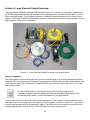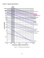
1
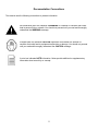
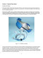
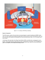
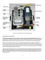
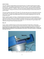
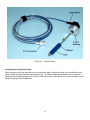
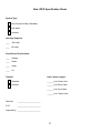
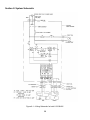
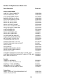
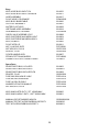
Large Diameter Filter Scavenger Oil Water Separator System Installation and Operation Manual Rev 2/26/2013 P/N ORS999001009 Table of Contents Section 1: System Description …………………………………………………………………………………… Function and Theory …………………………………………………………………………………………… Large Diameter Dangle Scavenger ………………….……………………………………………………….. Section 2: System Installation ………..……………………………………………………………………………. Section 3: System Operation ……………………..……………………………………………………………….. Section 4: System Maintenance ………………………………………………………………………………….. Section 5: System Troubleshooting ………………………………………………………………………………. Section 6: Large Diameter Dangle Scavenger …………………………………………………………………… Section 7: System Specifications …………………………………………………………………………………. New LDFS Specification Sheet ……………..………………………………………………………………… Section 8: System Schematic …………………………………………………………………………………….. Section 9: Replacement Parts List ………………………………………………………………………………... Appendix A: Recoverable Materials …………………………………………………………….………………... Appendix B: Decontamination Procedures …………………………………………………….………………… Warranty and Repair ……………………………………………………………………………………………….. 1 3 3 8 9 11 14 17 22 26 27 28 29 31 33 36 Documentation Conventions This manual uses the following conventions to present information. An exclamation point icon indicates a WARNING of a situation or condition that could lead to personal injury or death. You should not proceed until you read and thoroughly understand the WARNING message. A raised hand icon indicates CAUTION information that relates to a situation or condition that could lead to equipment malfunction or damage. You should not proceed until you read and thoroughly understand the CAUTION message. A note icon indicates NOTE information. Notes provide additional or supplementary information about an activity or concept. 2 Section 1: System Description Function and Theory The Geotech Large Diameter Filter Scavenger (LDFS) is a unique filtering and pumping system designed for the efficient recovery of hydrocarbon product from surface water. The system is portable and electrically safe for use in hazardous locations. The heart of the LDFS system is a floating oil/water separator which passes recovered oil to a remote pump and control assembly. Actual separation of oil or other hydrocarbons from water is effected by a mesh screen located in the floating buoy assembly (shown in Figures 1-1 and 1-4). This screen is specially treated to pass oil and repel water. The screen is therefore termed oleophilic/hydrophobic (oil loving/water fearing). Figure 1-1 – LDFS Buoy Assembly During normal operation, the buoy supports the oil/water separator cartridge precisely at the oil/water interface (as shown in Figure 1-2). When oil or fuel contacts the screen, the hydrocarbon flows through while water is repelled. Oil collects in the buoy base until enough accumulates to lift the oil float and turn on the remote pump. In this way, water-free oil is pumped automatically into a recovery tank. If, for some reason, water enters the buoy, the water float in the buoy base shuts off the pump and illuminates a red alarm indicator. This feature prevents contamination of the recovered product. 3 Figure 1-2 – Cut away of LDFS Buoy Assembly System Components The LDFS system consists of two parts that can come packaged in an optional weatherproof NEMA 3 rated case. The case is opened by unsnapping its eight latches and lifting off the top with its two handles. Held in the top of the case is the complete buoy assembly with its input hose and control cable. A 20’ (6 m) output hose is also included. In the bottom of the case there is the Pump Control Module (PCM), a tankfull probe, a spare parts kit, and a manual. There is portal access on each side of the case. Looking down on the system, the PCM appears as in Figure 1-3, the portal on the right permits access of the input hose and the cables from the buoy and tankfull probe. The left portal is for the output hose and power cord. 4 Figure 1-3 - LDFS Pump Control Module Assembly Buoy Base and Control Cable The LDFS buoy assembly (as shown in Figures 1-1 and 1-2) is a two piece anodized aluminum housing. It functions as the receptacle for the product after it passes through the oil/water separator cartridge. The control cable jacket is over coated with polyurethane for abrasion and chemical resistance. The cable runs through a strain relief and plastic elbow before entering the buoy where it is secured into the buoy base with epoxy. On the center rod of the buoy base is a 2 1/2” (64mm) diameter metal float with a magnet embedded in its bottom. This float controls the pump. When approximately 400ml of hydrocarbon product accumulates in the buoy, the float rises, trips a sensor and closes the control circuit which turns on the pump. Approximately 200 ml is pumped before the float seats again, opening the circuit and turning off the pump. Hence, a small amount of residual product always remains in the buoy. The second and smaller float in the buoy base is used to shut off the system should water somehow enter the buoy. The water shutdown float is denser than oil but less dense than water. When the float rises, a sensor shuts down the pump and actuates an alarm indicator light on the control module. The water alarm float may be disabled as discussed in Section 3. The control circuit for the buoy assembly is diagrammed in Section 8, System Schematic. 5 Intake Cartridge The intake cartridge is clamped between the buoy base and the lid. The base and lid have smooth, seating surfaces by which the cartridge is positioned and makes a water tight seal. The intake cartridge is available in two mesh sizes - a standard 100 mesh for gasoline, kerosene, etc. and a coarser 60 mesh for hydrocarbons with viscosities between 100 – 400 SSU’s. The mesh sizes represent tradeoffs between oil flow and the ability to hold back water. The larger the hole sizes, the more easily oil flows through, but the more likely water is to enter the system. The screen is stainless steel with a PTFE coating. The 100 mesh screen has a blue coating while the 60 mesh is colored green. The screens are molded to an anodized aluminum frame with epoxy which has two affixed Viton o-rings. The cartridge is then sealed between the buoy lid and base by tightening the cover cap to the threaded center post. Section 7 contains a graph on viscosity vs. temperature and the recovery rates of common hydrocarbons. Geotech Sales can also help you to determine which cartridge is best suited for the product being recovered. A Hydrocarbon Viscosity Test Kit is also available from Geotech. The test kit can be used to evaluate the product being recovered to help you determine the best cartridge type to use. See Section 9 for part numbers to the Hydrocarbon Viscosity Test Kit User Manual and test kit. Buoy Lid The lid is made of anodized aluminum and has four blue polyurethane floats that serve as edge guides (thereby keeping the unit from getting hung up) as well as keeping the unit afloat. Flotation is provided by the four lid floats and the orange output hose floats. The lid floats may be adjusted with spacers to change the floating height of the oil/water separator cartridge with respect to the oil/water interface. Figure 1-4 shows a lid float with the spacers adjusted for a rough water position. See Section 3 for further information on changing the float height of the buoy. Figure 1-4 – Detail of float (lowered) for rough water position. 6 Pump Control Module (PCM) The PCM is designed for rugged use either with the buoy or as a portable transfer pump and is explosion proof (EP) and Intrinsically Safe (IS) for Class 1, Division 1, Group D hazardous locations. The PCM contains several sub-assemblies which are described as follows. Explosion Proof (EP) Control Switch Box The EP control switch box houses the ON/OFF switch, the HAND-OFF-AUTO control switch, and an alarm indicator. The box also contains the receptacle connection for the buoy and tankfull cables, various control relays and the fuse blocks. Pump/Motor The motor (1/4HP, 1725 rpm) is explosion proof and has thermal overload protection. A self priming gear pump is attached to the motor with a three part, flexible coupling. This motor is used in both the 115V and 230V models and is factory wired for the correct voltage and rotation. Alarm Indicator This red indicator signals either a tankfull condition or the presence of water in the buoy. During a tankfull condition, the indicator will remain illuminated with the control switch in the OFF position. During a water alarm condition, the indicator will go out when the control switch is turned to OFF. Weatherproof connectors These ports contain Intrinsically Safe wiring and provide receptacles for the tankfull and buoy control connectors. 3-Channel IS Relay The EP box contains a 3-channel, IS relay to which the buoy and tankfull probe are directly connected to. In addition, the EP box also contains other control relays, the fuse blocks, and a potentiometer relay (for timing). Tankfull Probe The tankfull probe (Figure 1-5) is a float actuated fluid level sensor that fits into the collection tank and shuts off the pump when the tank is full. It also acts as a safety device in that it needs to be connected for the LDFS to function. Consult Geotech for other options when a tankfull probe is not required for your recovery needs. 7 Figure 1-5 – Tankfull Probe. Large Diameter Dangle Scavenger When access to product is restricted by the hole size and depth, Geotech can offer you a modified recovery system called the Large Diameter Dangle Scavenger. The Dangle Scavenger allows the user to lower the pump/motor assembly separately into a well for access to the buoy. See Section 6 for more information on the Dangle Scavenger and its application. 8 Section 2: System Installation Pump Control Module (PCM) Since both the input hose and the control cable must be connected to the control module, place the case bottom with the module as close to the recovery point as possible. Ideally, the PCM should be placed within 12.5’ (3.75m) of the buoy (the length of the input hose/control cable), and within 20’ (6m) of the product recovery tank (the length of the output hose unless additional lengths are ordered). Confirm that the product recovery tank is grounded and is connected to the grounding clip on the output hose. The two input connections to the PCM (hose and cable) are made through the right portal of the optional weatherproof case. Remove the black portal cover by twisting it counterclockwise. The cover is tied to the dust plug at the pump input. Remove the dust plug by opening the two handles on the input coupler. Store the portal cover and dust plug within the back of the case (if no case, then place the plug within the spare parts bag). Run the input hose and control wire through the right portal. Connect the input hose to the input coupler. This is easily done by closing first one, then the other handle on the coupler. Next, locate the 3-pin buoy control cable receptacle. Carefully connect the control cable to the receptacle on the EP box. The connector and receptacle are slotted. Line up the slots, push on the connector and tighten it clockwise. Now remove the left portal cover by twisting it counterclockwise. The cover is tied to the dust cap at the pump output. Remove the dust cap by opening the two handles on the cap. Store the portal cover and dust cap within the back of the case (if no case, then place the cap within the spare parts bag). Connect the output hose to the output adapter, running it through the left portal. As with the input hose, this is easily done by closing first one, then the other handle on the output coupler. Run the free end of the output hose to the recovery container and connect its coupler securely to the tank. Confirm that the spring clip at the end of the hose is grounded. Now connect the tankfull probe. The tankfull probe comes with a brass 3/4” NPT fitting that is attached to a 2” aluminum reducer fitting for use with a standard 55 gallon (208 liter) drum or larger tank. Remove the 2” reducer fitting for a 3/4” bung hole. Adapters are available for other fittings. The tankfull float will rise when the product level is approximately 4” (102 mm) from the top of the recovery tank. The standard tankfull assembly comes with a 25’ (7.5m) cable, but alternate lengths can be provided by Geotech. Once the tankfull probe is fitted onto the recovery tank, run its cable next to the input hose into the right portal on the PCM. Locate the 8-pin tankfull control cable receptacle. Carefully connect the control cable to the receptacle on the EP box. The connector and receptacle are slotted. Line up the slots, push on the connector and tighten it clockwise. The tankfull and buoy cable connectors are not interchangeable. The tankfull cable must be connected for the system to operate. This also acts as a safety function in case the cable is severed. When the tankfull float rises to the top of its travel, the pump will automatically turn off and the red indicator on top of the control switch box will be illuminated. The red alarm indicator will also be illuminated if the tankfull connector becomes disconnected or if the cable is accidentally cut. 9 Buoy Placement For recovery well sites, lower the buoy by the hose/cable and a cord through the cover handle. Be careful to maintain the buoy horizontally when breaking the oil/water surface. If there is 1/2” (13mm) or more of product in the well, the buoy will begin recovering product immediately and will sink lower in the water until the system is turned on. When placing the buoy by hand, do not twist the cover handle as this will loosen the cartridge and let water pass into the buoy. The buoy should be level on the oil/water surface so that it recovers oil at the fastest rate, due to the fact that the cartridge will have the maximum amount of area exposed to the oil to be recovered. Only if the system is floated correctly will maximum efficiency be achieved. For example: Assume the buoy is floating in clear water. Through factory pre-set ballasting, the four lid floats sink into the water about 1/8” (3.0 mm) exposing the cartridge to the oil/water interface. The intake cartridge passes oil and its derivatives. The oil “wets” the screen and prevents water from entering the cartridge. The screen is thus termed oleophilic/hydrophobic (oil loving/water fearing). When placed in the water, the ridge on the four lid floats will just break the surface. The hose float closest to the buoy may be adjusted for proper buoy flotation. Once floated on the water and connected by the hose and control wire to the pump control module, the buoy will recover and pass only hydrocarbon product through the input hose, pump and output hose to the collection container. Connect Power Before supplying power to the PCM, confirm that the system is grounded and set the control and power disconnect switches to the OFF position. The power cord is normally supplied with an EP plug whose ground prong is slightly longer than the other two. This plug must be used with a compatible EP receptacle (also available from Geotech). 115 and 230V EP receptacle part numbers can be found in Section 9. When using a portable generator (1.5 KVA minimum), a ground to earth must be made. Connect one end of the ground cable to either the terminal marked GROUND or to an unpainted metal area on the generator. Connect the other end of the cable to a metal stake driven into the ground or to any grounded metal structure. See the National Electric Code Handbook (Section Grounding Electrodes) for details on grounding. Run the power cord through the right portal and connect the plug to a suitable power source. The system is now ready for operation. Before activating the system, please read the additional instructions in Section 3. 10 Section 3: System Operation Read this section prior to activating the LDFS system. Product Type Recovered The LDFS system will recover any non-polar liquid with density less than water. This leaves out such dense materials as chloroform, carbon disulfide, carbon tetrachloride, and Freon. Certain materials will dissolve the ABS cartridge seals, but the unit may be used in an emergency or if concentrations of such materials are low. These materials are usually aromatics: common ones are pure, 100% benzenes, xylenes, toluenes, and styrene monomers. The aluminum buoy/EFP cartridge system can handle these materials. Common materials besides gasoline, kerosene, and oils which will readily be recovered are: hexanes, heptanes, octanes, petroleum, napthas, pentanes, or mixtures of the above. An extensive listing of recoverable materials can be found in Appendix A. Buoy Operation Once product enters the intake cartridge, the cavity in the buoy base will begin to fill. On the center of the base is a float with a magnet embedded in its bottom. This float controls operation of the pump. The other smaller black float is used for turning off the system should water enter the buoy. This may occur when the cartridge is poorly seated or when the buoy is not floated properly. Other causes of water leakage are given in Section 4. When 400 ml of product have entered the buoy, the float rises, closes the control circuit and turns on the pump. After 200 ml have been pumped, the float seats again and turns off the pump. The smaller float is denser than oil and less dense than water. If the buoy cavity contains 40% water, this float will rise, turn on the red alarm indicator light and shut off the pump. Turning the control switch to HAND will pump out the buoy and reset the water float. The water float may be disabled as follows: Thread the white Nylon bushing down on the water float shaft until it bottoms out against the float. This will hold the water float in the DOWN position and prevent the pump from shutting off when water is detected in the buoy. Hydrocarbon exits the buoy through an elbow in the bottom of the base. It is pulled through the 3’ (1m) length of corrugated FEP hose and through a 3/4” NPT PVC check valve. The check valve functions as a foot valve for the system to hold the prime on the pump. The input hose has a 3/4” (19mm) quick disconnect adapter at its end to permit connection to the pump input. Skimming Only Operation In situations when the water is frequently rough or the cartridge has become contaminated with detergent it may be necessary to float the buoy above the oil/water interface in order to prevent water intrusion. The two pair of washer shims above each lid float may be placed between the lid and the float as shown in Figure 1-4. Note that a total of three float positions are possible with the spacers provided. 11 To convert the buoy for skimming operations: 1. Unscrew the eight 1/4-20 nylon cap nuts located on top of the lid. 2. Carefully pull out the four floats and re-insert them with either one or two spacers between the float and the lid (see Figure 1-4). 3. Rethread the cap nuts. With one spacer between the lid and the float, the buoy will skim to approximately 1/10” (2.5 mm) of product. With two spacers between the lid and the float, the buoy will skim to approximately 1/5” (5mm) of product. The Scavenger is limited by: 1. Water Parameters 2. Product Type Recovered Water Parameters The water parameters are classified into physical, chemical, and debris divisions. Physical State The buoy is designed as a surface follower to minimize its heave and pitch. When the water is “rough”, the effect is to reduce the ability of the cartridge to repel water. Under certain conditions, the cartridge will pass water. The slight density difference of the two is inconsequential for the buoy flotation. If the unit is used exclusively in sea water, certain parts may need long-term replacement due to salt water corrosion. Chemical State The cartridge will collect water if surface tension is reduced. Detergent or surfactant concentrations greater than 100 ppm (grams/liter) will cause the cartridge to pass water. If the Scavenger is placed in an area with no oil to “wet” the screen, natural biological growth (called “slime” which is the first step in the plankton, algae, and barnacle food pyramid) will reduce the ability of the cartridge to repel water. Since this slime or fouling increases drastically in warmer water, the cartridge will pass water more easily warm environments. In general water-in-oil emulsions will pass through the membrane. Oil-in-water emulsions pass less easily depending on the actual percentage of oil. The oil/water interface always has both emulsion types present as well as high concentrations of surfactant. Hence, whenever the Scavenger is dealing with only thin layers of oil, the percent of interface is high and some water may pass through the cartridge. Debris Debris causes reduction of oil flow rate. Most debris accumulates on the mesh when a large volume of oil is going through the cartridge. Debris is easily removed when cleaning the cartridge. Often the unit may be gently pulled up and down in its site area to remove some of the accumulated debris. 12 Activate the LDFS System After reading this section, turn the power disconnect switch to the ON position and turn the control switch momentarily to the HAND position. The pump will run. The PCM may be used as a transfer pump at any time by disconnecting the buoy (with its hose and cable) and running the PCM with the control switch in the HAND position. Once the pump has run in the HAND position, turn the switch to AUTO. When the buoy has recovered approximately 400 ml of product, it will automatically turn on the pump. The pump will run until about .05 gallons (200ml) is moved through the system. If the buoy is recovering product at more than 4 GPM (15 liters), the pump will run continuously until the product slick thickness is reduced to less than 1/2” (13mm). If required lift is excessive and/or if volatile product is being recovered, the pump may require priming. Once the buoy base has accumulated some product, an easy way to prime the system is to lift the buoy by its lowering rope or handle to the level of the PCM, allowing product to easily move towards the pump. An alternative priming method is to disconnect the input hose from the pump, fill the hose with product and reconnect it to the pump. Loss of prime can be prevented by placing the pump at a low point in relation to the buoy and by developing both the input and output hoses in loops. After all components are in place and the system is verified as operational, the cover of the optional case should be replaced and latched to provide a weatherproof container for the pump and its controls. If a case did not come with the unit, then take measures to protect the PCM with an alternate cover. 13 Section 4: System Maintenance Proper functioning of the Gravity Feed Filter Scavenger requires that the oil/water separator cartridge, buoy and hoses be regularly monitored for leaks and clogs. Maintenance procedures for these components are described within this section. Normal maintenance requires an occasional cleaning of the cartridge which in high flow and/or debris laden situations may clog and cut down on flow. While normally only petroleum and its products are collected, water that has emulsified with the oil or highly detergent laden water will pass through the cartridge. In contrast, the electrical components of the PCM are factory sealed and require minimal maintenance. Oil/Water Separator Cartridge Two basic types of problems may afflict the oil/water separator cartridge. These are clogging of the separator screen (optional) and leakage of water into the cartridge. Screen Clogging Although the separator screen has been designed with corrugations to provide maximum surface area, build up of debris will reduce the rate of hydrocarbon recovery. In most well sites, debris clogging is a minor problem because the hydrocarbon has already been filtered somewhat in moving through the earth. On settling ponds, where industrial waste oil must be recovered, screen clogging is potentially a more serious concern. In the event of screen clogging, remove and disassemble the buoy, then gently clean the intake screen using a soft brush and other hydrocarbon (such as kerosene or diesel). Then re-install the buoy. It may be necessary that you install a separate screened area within the pond for the buoy to be placed into in order to prevent future clogging. Water Leaks (also used for Cleaning the Buoy Assembly) Factors that may cause water to leak through or past the oil/water separator cartridge include improper buoy flotation, improper sealing of the cartridge to the buoy housing, improper priming, and the presence of detergents on the screen itself. If a problem with the oil/water separator cartridge is suspected, the following procedure should be followed. 1. Unthread the buoy cover handle and lift off the buoy lid. 2. Lift the cartridge from the buoy base. 3. Wash and rinse the cartridge and the sealing surfaces on the buoy base and lid. Use kerosene, hexane or any common aliphatic hydrocarbon. DO NOT USE other cleaning solvents, aromatic or ketone. DO NOT USE detergents unless the unit is then carefully washed in water followed by one of the approved solvents mentioned above. Confirm that the oil and water floats are free to move up and down through the full range of their travel. Clean the floats with one of the approved solvents. 4. If the cartridge is visibly damaged, replace the cartridge. 5. Inspect the aluminum surface of both the buoy and lid. If there is a dent or bend in the metal where the cartridge o-rings rest then water can leak through these areas. 14 6. Once the cartridge and its two sealing surfaces have been cleaned, prime the screen with kerosene (or with the hydrocarbon to be collected), then re-insert and center the cartridge in the base. Confirm that the cartridge is not wet with water before installation. 7. Set the buoy lid in place (be careful to line up the input hose and control cable between two of the blue floats as you do.) Tighten the cover handle. Only moderate torque is necessary for a water tight seal. 8. Arrange the two floats on the urethane hose and adjust the check valve for proper buoy flotation. In order to achieve proper buoy flotation it may be helpful to replace the straight fitting at the end of the check valve with an elbow fitting. Buoy Lid and Cover Cap The cover cap is aluminum with a 5/16-18 tapped center hole. Its handle provides easy lifting and tightening of the buoy assembly. Three screen covered holes go through the buoy lid and allow air to escape from the buoy as product accumulates. The vent holes are protected from rain by the cover cap, which is held off the lid surface by the three nylon bolts in the lid. Input Hose Since the buoy and output hose are on the suction side of the pump, it is essential that they be free of leaks or obstructions. A convenient way to check the system for leaks is to fill the line with water and cap the output hose with the dust cover from the pump output. This will pressurize the system to approximately 65 psi (4.5 bar) (the setting of the relief valve) and will reveal any leaks in the system. Exercise caution when pressurizing the system to check for leaks. Always wear appropriate safety equipment. Power Cord The power cord consists of 25’ (7.6m) of 14/3 SEO cable with an EP plug at one end and an elbow into the EP box at the other. The load end of the cord runs through a seal-off fitting and then through the elbow into the EP box. In 115VAC systems, the three wires of the power cord are Black = Line, White = Neutral, Green = Ground. In 230VAC systems, the wires are Black and Red = Line, Green = Ground. The cord is selected for flexibility, hard usage and chemical resistance. The cord should never be immersed in product and, like all power cords, never subjected to abuse. If the power cord is damaged, the National Electrical Code requires a new cord and seal off be installed. Tankfull Probe The tankfull probe is designed to fit into either 3/4” or 2” NPT bungs. The tankfull is failsafe in that a broken cable connection will stop the pump. A damaged tankfull float may be replaced by marking and removing the stop collar. The float magnet is located at the top of the float. The Filter Scavenger will not operate with the tankfull probe disconnected. 15 Motor Though the motor is used in explosion proof applications, it does not mean that it can be exposed to water. Whenever possible, keep the control panel housed within the optional case or other cover during operation. Pump LDFS systems use a 4 GPM (15 lpm) pump with modified carbon bearings and Viton seals. The pump has a spring loaded relief valve set at 65 PSI (4.5 bar) and is connected to the motor by a three part flexible coupling. The pump does not require additional lubrication as long as it is being used to pump lubricating hydrocarbons. However, after pumping water, squirt nondetergent oil into the intake opening of the pump to keep the gears lubricated. Also, lubricate the pump this way before putting the unit into storage. Do not allow water to remain in the pump during storage. A damaged pump will either seize or will not prime and should be replaced as follows: 1. Unplug the PCM from its power source and remove all hose and cable attachments from the PCM. 2. Remove the PCM from the case bottom by undoing the four retaining wing nuts (for those units in a case). 3. Remove the pump/motor coupling cover with an Allen wrench. 4. Remove the mounting hardware for the pump’s “L” bracket then remove the pump coupler from the pump shaft with a hex wrench. 5. With 1/2” wrenches, unscrew the four bolts at the pump and remove it from the “L” bracket. 6. Unthread the input and output fittings from the pump (remember the orientation of the parts). 7. Reverse the above procedures to install the new pump (when re-attaching the pump coupler, the shaft should be 1/16” (1.59mm) inside the hole edge). Leave about 1/16” (1.59mm) of space within the flexible coupler when securing the “L” bracket in place, then use a ruler to align the pump face to the motor face. Geotech recommends that all explosion proof and Intrinsically Safe enclosures be opened and inspected on an annual basis. Check for corrosion, water build-up, loose connections and damaged wires. Any faulty components should be repaired or returned to Geotech. For service call (800) 833-7958 or (303) 320-4764. See Section 9 for a complete list of LDFS replacement parts provided by Geotech. 16 Section 5: System Troubleshooting Disconnect power before opening any enclosure. Carry out troubleshooting procedures in a non-hazardous (non-flammable) location. In this section possible malfunctions are listed along with suggested procedures for determining their causes. In many cases, these troubleshooting procedures can be simplified by using the three LED’s on the 3-channel relay as diagnostic indicators of system status. The LED’s, located on the 3-channel relay inside the control panels EP box (see Section 8, System Schematic), indicate the positions of the oil and water floats inside the buoy, as well as the tankfull float in the recovery tank. An illuminated LED indicates a closed switch. The following table summarizes the conditions which cause each of the LED’s to be either ON or OFF. LED A B C ON OFF 1. Water float in buoy is up. 2. Short between “A” & “C” on buoy, buoy connector, or in wiring. 3. Defective relay. 1. Oil float in buoy is up. 2. Short between “A” & “B” on buoy, buoy connector, or in wiring. 3. Defective relay. 1. Tankfull float is down. 2. Short between “A” & “B” on tankfull, tankfull connector, or in wiring. 3. Defective relay. 1. Water float in buoy is down. 2. No connection between “A” & “C” on buoy, buoy connector, or in wiring. 3. Defective relay. 1. Oil float in buoy is down. 2. No connection between “A” & “B” on buoy, buoy connector, or in wiring. 3. Defective relay. 1. Tankfull float is up. 2. No connection between “A” & “B” on tankfull, tankfull connector, or in wiring. 3. Defective relay. Table 1 – LDFS system status as indicated by LED’s on 3-channel relay Problem: Motor does not run on HAND or AUTO. Solution: 1. Check power source. 2. Check recovery tank. If recovery tank is not yet full then check for defective alarm indicator bulb on control panel box (a faulty light will stop control panel operation). 3. Check tankfull probe. Disconnect tankfull cable connector from connector box and jumper sockets A & B in the receptacle. If motor runs, the problem is in the tankfull probe itself. Confirm that the tankfull float is free on its shaft. When the tankfull probe is disconnected, the red indicator light will come on. See tankfull diagnostic later in this section. 4. Move system to a nonhazardous location. Open the EP box, plug in the control panel and turn the power switch to the ON position. Jumper sockets A & B in the tankfull receptacle. The red LED (marked “C”) on the top of the 3-channel relay should be illuminated. If the LED is not illuminated, disconnect power and check the continuity between #4 & #5 on the relay. If this continuity check reveals an open circuit, call Geotech for assistance. 17 5. If no open circuit is found and the motor still does not run, disconnect power, open the EP box and check the fuses. 115VAC systems will have one 20 AMP fuse and one 1 AMP fuse. All 230VAC systems have two 8 AMP fuses and one 1 AMP fuse. Replace fuses if necessary and reseal the box. When resealing any explosion proof box, clean the cover flange and coat it with LUB-G flame joint grease. 6. If the fuses are good, transport the system to a nonhazardous location and use the following procedure to test the DPDT relay. Referring to Section 8, System Schematic, run a jumper from the Normally Open contact to the Common on the DPDT relay. Be careful not to short the switch contacts to the EP box. Apply power to the system. If the motor runs with the control switch in the HAND position the mechanical relay must be replaced. 7. If the motor does not run, disconnect power and remove the jumper attached in Step 6. Now with the control switch in the HAND position, check the resistance between the Normally Open contact on the relay and pin 4 on the solid state relay (SSR). If the meter indicates a short circuit, replace the SSR relay. If the meter indicates an open circuit, check for loose or broken wires. If none are found, call Geotech for assistance. Problem: Motor runs on HAND but not on AUTO. Solution: Most problems on the AUTO setting can be traced to float malfunctions. Examine the center (oil) float and confirm that it is not filled with oil (heavy) and that it can freely move up and down throughout its normal travel. Also check to see that the smaller (water) float is not stuck in the up position and that there are no obstructions between the float and its seat. If the Buoy was cleaned, verify that neither float has been re-installed upside down. If a float malfunction is not the problem, examine the control cable for cuts and breaks, then use an ohmmeter to test the buoy control circuit (refer to Section 8, System Schematic). In the buoy cable receptacle are three pins labeled A, B, and C. With the meter on the R x 1 scale, these receptacles should read electrically as follows: A-C Open when water float is down. A-C Closed when water float is up. A-B Open when the oil float is down. A-B Closed when the oil float is up. A-B Opens when both oil and water floats are up. 18 Problem: Motor runs continuously on AUTO. Solution: 1. Disconnect the buoy to determine if the oil float is stuck in the up position. 2. If the motor continues to run, the problem is not in the buoy. Disconnect the tankfull and check for a fault in the probe as described later in this section. 3. If neither the oil float nor the tankfull is found to be faulty, check for a solid state relay (SSR) failure. Unplug the control panel from its power source, move to a nonhazardous area and open the EP box. Lift off the EP box cover and lay it to the side of the box. Remove the 1 AMP fuse and apply power to the system. If the pump runs, the SSR is faulty and must be replaced. 4. If the SSR is not faulty, replace the fuse and check the resistance across the HAND-OFF-AUTO switch (refer to Section 8, System Schematic). Move the switch from HAND to OFF. The meter should show a change from a closed circuit to an open circuit. If the switch cannot be made to operate properly, call Geotech for assistance. 5. If the control switch is not at fault, check the function of the 3-channel relay. Check the resistance between pins 11 and 12 on the relay. If the meter indicates a closed circuit, check for shorted wires. If none are found, call Geotech assistance. Problem: System runs normally but alarm indicator remains on. Solution: Disconnect power, move the system to a nonhazardous location and open the EP box. Check the resistance between pins 9 and 10 on the 3-channel relay. If the meter indicates a closed circuit, check for shorted wires. If no shorts are found, the relay must be replaced. Call Geotech for assistance. Problem: Buoy fills with water. Solution: 1. Check the floating height of the buoy. Adjust the floats if necessary. 2. Check for a damaged oil/water separator screen. Check for the presence of detergents in water. Occasionally, water which has leaked into the buoy may become trapped below the oil in the output hose. After the cause of the leak has been cured, this water may leak back into the buoy and shut down the system. 3. Check for dents or scratches on the buoy surface near the oil/water separator sealing ring. Such irregularities can cause water leakage around the screen. On older models, aluminum lids were made of a soft alloy that could be distorted by rough handling. A distorted lid could change the position of the floats thus changing the level of buoy flotation and allowing the intrusion of water. 4. Check for leaks in the input hose and fittings. 19 Problem: Buoy fills with oil and sinks. Solution: 1. Check for an air leak in the FEP input hose. If the hose develops an above-water leak it can cause the pump to lose its prime. The buoy will then fill with oil and sink. 2. Check for a faulty pressure relief valve. The pump contains a pressure relief valve for overpressure protection. If water is allowed to remain in the pump, this valve may corrode and leak thereby causing the pump to lose its prime. 3. Check for a stretched, collapsed or kinked input hose. The FEP input hose is quite flexible. It is, however, sensitive to being stretched and bent at the same time. Once the hose is damaged in this manner, the suction from the pump may collapse the hose completely. In such cases, the buoy will not empty and will sink. 4. Check for a pinched output hose. A pinched or restricted output hose may cause the pump relief valve to open, thus halting the flow of oil. The buoy will then fill with oil and sink. Problem: Pump/motor taking too long to come on. Solution: Unplug the control panel from its power source, move to a nonhazardous area and open the EP box. Verify that the potentiometer is set all the way to 0.1. A very long delay may mean a damaged potentiometer. Call Geotech for assistance. Problem: Tankfull Probe or Alarm Indicator Light not operational. Solution: The control panel will not operate if there is a cut in the tankfull probe cable or when the alarm indicator light is burned out. These are built in as safety features. Whenever the tankfull probe is disconnected, the red indicator light will come on when applying power to the control panel. All alarm light issues must be resolved prior to using the system. If the light does not come on after removing the tankfull probe, then replace the bulb. If this doesn’t work, then there may be a fault in the internal circuitry. To check for a faulty tankfull probe, do the following: 1. Disconnect the tankfull cable connector from the control panel and jumper sockets A & B in the control panel receptacle. If the motor runs in HAND then the problem is in the tankfull probe itself. 2. Confirm that the tankfull float moves freely on the shaft. If the probe was cleaned, verify the float was not put back on upside down. 20 3. Check for proper function of the probe. Using an ohm meter on the R x 1 scale, the following pins should read electrically as follows: A-B Closed when tankfull float is down. A-B Open when tankfull float is up. E From pin E to any metal part of the probe there should be continuity. Any deviation from this test means the probe is faulty. Contact Geotech for assistance. 21 Section 6: Large Diameter Dangle Scavenger The Large Diameter Dangle Scavenger (LDDS) system (Figure 6-1) is comprised of the same equipment as the LDFS except that the motor/pump assembly is mounted separately to a durable stainless steel “L” frame with an attached eyebolt. The motor/pump assembly is therefore shipped separately from the Pump Control Module. The purpose of the Dangle Scavenger system is to allow access to product on water surfaces found in deeper wells or vaults, such as manholes. Figure 6-1 – Large Diameter Dangle Scavenger (with optional winch) System Components The LDDS system consists of three parts, two of which come packaged in an optional weatherproof NEMA 3 rated case. The case is opened by unsnapping its eight latches and lifting off the top with its two handles. Held in the top of the case is the complete buoy assembly with its input hose and control cable. A 20’ (6 m) output hose is also included. Of course, alterations to the buoy cable length and output hose length may be necessary to accommodate the distance between the motor/pump depth and the PCM and recovery tank location. Consult with Geotech on unit specifications. In the bottom of the case is the PCM, tankfull probe, spare parts kit and a manual. There is portal access on each side of the case. Looking down on the system, the PCM appears as shown in Figure 6-2). The portal on the right permits access of the buoy and tankfull cables. The left portal is for the power cord coming from the motor/pump assembly (Figure 6-3) and for the PCM power cord out to a power source. 22 Figure 6-2 – Dangle Scavenger Pump Control Module Figure 6-3 – Dangle Scavenger Motor/Pump Assembly After attaching the buoy output hose to the input side of the pump, the buoy, along with the motor/pump assembly, can be lowered into the hole with a winch attached to the eyebolt. Figure 6-4 is an example of a Dangle Scavenger setup within a well. 23 The winch assembly is optional from Geotech. See Section 9 for a list of available winches. After all components are in place and the system is verified as operational, the cover of the optional case should be replaced and latched to provide a weatherproof container for the pump and its controls. If a case did not come with the unit, then take measures to protect the PCM with an alternate cover. Figure 6-4 – Well configuration for the Large Diameter Dangle Scavenger 24 System Specifications The following specifications also apply to the LDFS System as well. Applications: Trenches, manholes, small bodies of water, and wells 24” (61.5 cm) in diameter or larger with fluctuating water table levels. Product Recovery Rate: Up to 4 gpm (15.4 lpm) @ 65 PSI Note: Dangle Scavenger flow will diminish with depth and length of output hose. Options: Spare filter membranes (mesh size 100 and 60), salt water duty system, aromatic duty system, winch assembly (71 feet/21.6 meters and 110 feet/33.5 meters), modifications for deep wells. Custom cable, and hose lengths available (Please call Geotech at (800) 8337958 to discuss your special applications.) 25 Section 7: System Specifications Figure 7-1 - Viscosity chart and temperature 26 New LDFS Specification Sheet System Type: Non-Corrosive Water (Standard) Salt Water Aromatic Cartridge Supplied: ____ 100 mesh ____ 60 mesh Pump Power Requirements: ____ Voltage ____ Phase ____ Amps ____ Hz Tankfull: Cable / Hose Lengths: Standard _______ft./m Power Cord Aromatic _______ft./m Buoy Cable _______ft./m Input Hose _______ft./m Output Hose Serial No. _______________________ P.I.D. _______________________ Inspected by: _______________________ 27 Section 8: System Schematic Figure 8-1 – Wiring Schematic for both 115/230VAC 28 Section 9: Replacement Parts List Parts Description Parts List Pump Control Module CASE,FILT SCAV,COMPLETE DRAIN SCREEN,SS,1.5 OD FOOT,ELASTOMER,2.50"OD BARRIER,PORTAL,5-3/4"DIA PORTAL,RETAINER & COVER RELAY,I.S.,120V,3 CHAN RELAY,I.S.,240V,3 CHAN RELAY,110V,DPDT,10 AMP RELAY,230V,10AMP,DPDT,RCT RELAY,90-280VAC,25AMP MAX LIGHT,IND,RED,120V LIGHT,IND,RED,230V RELAY,120V,TIMER,LDFS RELAY,230V,TIMER,LDFS POTENTIOMETER,5MA,LDFS PUMP,4GPM,GRAPHITE/VITON MOTOR,1/4HP,115/230V,1PH COUPLING,MOTOR,1/2"X1/2" POWER CORD ASSY,115V,3/4" POWER CORD ASSY,230V,3/4",25FT PLUG,115V,EP PLUG,230V,EP RECEPTACLE,POWER,115V,EP RECEPTACLE,POWER,230V,EP BOX,EP,3/4",1 HUB CONTROL RECEPTACLE,3 PIN ASSY, POTTED, 2005 CONTROL RECEPTACLE,8 SOCKET, ASSY,POTTED, 2005 BOLT,SS4,3/8-16X6",EYE ORS026004 ORS026005 PPF028001 ORS036002 PPM026002 PPE014067 PPE014062 PPE014090 PPE014091 PPE014092 PPE102002 16020012 16020006 16020007 16020008 PPP005017 PPE018004 56020002 2011036-25 2012006 PPE017001 PPE017003 PPE046003 PPE046005 16020009 26020023 26020024 16600099 Tankfull TANKFULL ASSEMBLY TANKFULL ASSY,AROMATIC,FM TANKFULL FLOAT ASSEMBLY REDUCER,AL,2 TO .75,VENTED CONNECTOR,8 PIN,FEMALE CABLE 56020009 2010080 2010023 ORS535001 16120002 Output Hose HOSE,.75"x20',W/FTGS & GROUNDING CLIP HOSE,.75"x20',W/FTGS ORS037001 ORS037002 29 Buoy ASSY,HOSE,BUOY/INPUT,FM ASSY,HOSE,BUOY/INPUT,AROM,FM HOSE ASSEMBLY FLOAT,HOSE,1"ID,ORANGE ASSY,BUOY BASE/CABLE OIL FLOAT ASSEMBLY WATER FLOAT ASSY URETHANE HOSE ASSEMBLY HOSEBARB,NYL,7/8X3/4MPT CHECK VALVE ASSEMBLY,PVC ASSY,CARTRIDGE,#100 MESH,LIGHT ASSY,CARTRIDGE,#60 MESH,HEAVY ASSY,LID,BUOY FLOAT,LDFS LID NUT,1/4-20,CAP,SLTD NUT,HEX,NYL,5/16-18 SPACER,.75x.35 COVER HANDLE ASSY STRING,COTTON,#4,MILDEW CONNECTOR,3 SCKT,FEMALE CABLE 2010076 2010077 2010017 PPM020002 2010026 2010027 2010028 2010018 PPP002009 2010088 2010054 2010056 2010006 2010011 PPF025001 ORS761001 ORS362001 2010007 PPF040002 16120001 Spare Parts SPARE PARTS BAG,115V,LDFS SPARE PARTS BAG,230V,LDFS SPARE PARTS BAG,230V,LDFS,FM SPACER,.75x.35 FUSE,20A,250V,NON DLY,ABC FUSE,8A,250V,NON-DELAY FUSE,1A,250V,SLO-BLO WASHER,VITON,FOR KAMLOC NUT,HEX,NYL,5/16-18 2010002 56020001 2012068 ORS362001 PPE011014 PPE011015 PPE011026 PPP013002 ORS761001 ASSY,WINCH,STD DUTY,71FT 1000LB MAX ASSY,WINCH,HEAVY DUTY,110FT 2500LB MAX 2020005 2030001 MANUAL,LDFS,STANDARD NON-FM MANUAL,TEST KIT,HYDROCARBON VISCOSITY TEST KIT,HYDROCARBON VISCOSITY ORS999001009 26030020 86020001 30 Appendix A: Recoverable Materials In order for a material to be recovered by the Geotech LDFS, it must have the following properties: It must float on water. Its specific gravity must be less than 1.0 and its kinematic viscosity less than 100SSU, for use with the “light” oil filter cartridge, and between 100 and 400SSU for use with the “heavy” oil filter cartridge. This means that short chained alcohols, carbon disulfide, chloroform, carbon tetrachloride and other dense solvents which are heavier than water can only be recovered by using a Geotech Probe Scavenger. Solvents that are lighter than water can be recovered with the filter cartridges that come with the LDFS. See Section 7 and the Hydrocarbon Viscosity Test Kit User Manual for more information. The following will work with the average LDFS filters: Alkanes: e.g. pentanes, hexanes, heptanes, etc. Alkenes: e.g. 2-pentane, 3, 4-dimethyl-2-hexane, etc. Aromatic hydrcarbons: e.g. benzene, toluene, xylene, vinyl benzene, etc. Alcohols with 4 or more carbon atoms: e.g., nbutyalcohol, hexanol, octanol, etc. Esters with 5 or more carbon atoms: e.g. pentyl acetate. Mixtures of the above: fuel oils, gasoline, kerosene, mineral spirits, naphthas, etc. Mono-alkyl halides: e.g. ethylchloride, allyl chloride, etc. The Aromatic LDFS must be used to recover materials containing aromatic hydrocarbons. It has epoxy/EFP filter cartridge, FEP input hoses, modified floats, etc. Materials requiring an Aromatic LDFS are marked with an asterisk (*) on the following list. If the water in which the LDFS buoy is floating is very acidic or basic, a pH LDFS and buoy may be necessary. This LDFS employs all the features of the aromatic unit, as well as resistance to extreme pH conditions. This unit should generally be used when pH is lower than 5 or greater than 9 (requires specific information on the water and materials to be recovered prior to final specification of components for the pH LDFS). The following list is taken from a composite of materials deemed hazardous by: 1. Environmental Protection Agency, Hazardous Substances, Federal Register, December 30, 1975 2. Environmental Protection Agency, Contingency Plan, Region II for spills of Oil and Other Hazardous Materials for Inland Waters of Region II. 3. National Fire Protection Association, Fire Hazard Properties of Flammable Liquids, Gases and Volatile Solids, NFPA #325M-1969. Many other non-hazardous substances, not on this list, can also be recovered. Examples of this are the variety of Edible Vegetable Oils. When in doubt, materials should be tested using a Hydrocarbon Viscosity Test Kit. 31 All materials listed here will work with the LDFS System. allyl chloride amyl acetate amyl alcohol sec-amyl alcohol amyl benzene* amyl chloride (1chloropentane) tert-amyl chloride beta-amylene-cis beta-amylene-trans amyl ether amyl formate amyl maleate amyl propionate (pentyl propionate) amyl toluene* benzene* benzyl formate* bicyclohexyl (dicyclohexy) butyl acetate sec-butyl acetate butylbenzene* sec-butylbenzene* tert-butylbenzene* butylchloride (1chlorobutane) sec-butylchloride (2chlorbutane) ter-butylchloride (2-chloro-2-methylpropane) butyl butylrate tert-butyl carbinol (2,2dimethyl-1-propanol) butylisovalerate butylmethacrylate 2-chlorobutene-2 chloroethane 1-chlorohexane cumene (2-phenyl propane, osproply, benzene)* cycloheptane cyclohexane cyclohexene cyclohexyl acetate cyclohexyl benzene* cyclohexyl chloride cyclopentane cyclopentanol decane decanol 1-decene decylbenzene* diamylene Diesel Fuel #1 Diesel Fuel #2 O-diethyl benzene* m-diethyl benzene* p-diethyl benzene* diethylcyclohexane 3,3-diethylpentane diisopropyl benzene* 2,2-dimethylbutane 2,3-dimethylbutane 2,3-dimethyl-1-butene 2,3-dimethyl-2-butene 1,4-dimethylcyclohexane 1,4-dimethylcyclohexane-cis 1,4-dimethylcyclohexanetrans 2,4-dimethyl-3-ethylpentane (3-ethyl-2,4-dimethylpentane) 3,3-dimethylheptane 2,3-dimethylhexane 2,4-dimethylhexane 2,3-dimethyloctane 3,4-dimethyloctane 2,3-dimethylpentane 2,4-dimethylpentane dipentene 1,1-diphenylbutane* 1,1-diphenylpentane* 1,1-diphenylpropane* dodecene 1-dodecanol (lauryl alcohol) dodecylene (1-dodecene) ethyl acetate ethylbenzene* 2-ethyl-1-butene 2-ethylbutyl acetate 2-ethylbutyl acetate 2-ethylbutyl alcohol ethylcyclopentane ethyl formate 2-ethylhexyl chloride ethyl isobutyrate 3-ethyloctane 4-ethyloctane ethyl methacrylate ethyl propionate m-ethyltoluene (1-methyl-3ethylbenzene)* o-ethyltoluene (1-methyl-2ethyltoluene)* p-ethyltoluene (1-methyl-4ethyltoluene)* Fuel Oil #1(kerosene, range oil,coal,oil) Fuel Oil #2 Gasoline hendecane heptane (all isomers) 2-heptanol 3-heptanol heptylene (1-heptene) 32 heptylene-2-trans (2-heptenetrans) 1,4-hexadiene hexane 1-hexene 2-hexene hexyl acetate hexyl alcohol sec-hexyl alcohol (2-hexanol) isoamyl-alcohol isoamyl chloride (1-chloro-3ethylbutane) isoamyl butyrate (isopentyl butyrate) isobutane isobutyl benzene* isobutyl chloride isodecane isoheptane isophorone isoprene isopropyl bicyclohexyl Jet Fuels Kerosene methallyl chloride methyl methacrylate 2-methyl-1-butanol 2-methyl-2-butanol 2-methyl-1-butene 2-methyl-2-butene 3-methyl-1-butene methcyclohhexane 2-methylcyclohexanol 3-methylcyclohexanol 4-methylcyclohexanol methylcyclohexanone methylcyclopentadiene methylcyclopentane 2-methyldecane 1-methyl-3,5-diethybenzene* 2-methyl-4-ethylhexane 3-methyl-4-ethylhexane 2-methyl-3-ethylpentane 2-methyl-1,3-pentadiene 2-methyl-1,3-butadiene (isoprene) 2-methylpentane 3-methylpentane 2-methyl-1-pentanol 4-methyl-2-pentanol acetate 2-methyl-1-pentene 4-methyl-1-pentene 2-methyl-2-pentene methyl propionate methylstyrene* mineral oil (less than 45cs) mineral spirits naphtha nonane nonane (iso), 2methylloctane, 3methyloctane, 4methyloctane nonylbenzene* octane 2-octanol 1-octene octyl formate octyl alcohol (1-octanol) octyl chloride pentachlorophenol* pentane 3-pentanol petroleum, light crude Petroleum ether (benzene,naphtha) Pinane Propylbenzene (phenylpropane)* propyl chloride propyl propionate Stoddard solvents styrene (cinnamene, phenylethylene vinyl benzene)* 2,2,3,3tetramethylpentane 2,2,3,4tetramethylpentane Toluene* Toluol* 1,2,3-trimethylbenzene* 1,2,4-trimethylbenzene (pseudocumene)* 1,3,5-trimethylbenzene (mesitylene)* 2,2,3-trimethylbutane 2,3,3-trimethyl-1-butene 2,5,5-trimethylheptane 2,2,5-trimethylhexane 2,6,8-trimethylnonane 2,3,4-trimethyl-1-pentane 2,4,4-trimethyl-1-pentene 2,4,4-trimethyl-2-pentene 3,4,4-trimethyl-2-pentene Turpentine 4-vinyl cyclohezene vinyl propionate m-xylene* o-xylene* p-xylene* xylol Appendix B: Decontamination Procedures Some common decontamination solutions are listed below along with the contaminants they are effective against: Solution Effective Against Water Short-chain hydrocarbons, inorganic compounds, salts, some organic acids, other polar compounds. Basic (caustic or alkaline) compounds, amines, hydrazines. Acidic compounds, phenols thiols, some nitro- and sulfonic compounds. Non-polar compounds (such as some organic compounds) Dilute Acids Dilute Bases Organic solvents The use of organic solvents is not recommended because: 1) organic solvents can permeate and/or degrade protective clothing and 2) they are generally toxic and may result in unnecessary employee exposure to hazardous chemicals. When in doubt, use a dish washing liquid detergent. As a decontamination solution, it is readily available, is the safest of all the above, and is usually strong enough if used generously. The use of steam can also be effective for decontamination. A water-lazer (pressurized water) is exceptionally valuable. The following substances are noted for their particular efficiency in removing certain contaminants or for decontaminating certain types of equipment. Solution Effective Against Penetone PCB Contamination (since penetone may also remove paint, it is a good idea to spot-test before use) Phosphate free detergent Contaminated pumps Ivory liquid Oils Diluted HTH Cyanides Radiac Low level radioactivity Isopropanol Biological agents (should not be used on rubber products since it will break down rubber) Hexane Certain types of lab or sampling equipment (use of hexane is discouraged due to its flammability and toxicity) Zep General purpose cleaning Phosphate free detergent General purpose cleaning 33 Decontamination Solutions to Avoid Some decontamination solutions should be avoided because of their toxicity, flammability, or harmful effects to the environment. Halogenated hydrocarbons, such as carbon tetrachloride, should not be used because of their toxicity, possible incompatibility, and some because of their flammability. Organic decontamination solutions should not be used on personal protective equipment (PPE) because they may degrade the rubber or other materials comprising the PPE. Mercurials are sometimes used for sterilization. They should be avoided because of their toxicity. Chemical leaching, polymerization, and halogen stripping should all be avoided because of possible complications during decontamination. Sand-blasting, a method of physical removal, should be avoided because the sand used on the contaminated object usually needs to be disposed of as hazardous waste, a very costly proposition. Also, sand-blasting exposes personnel to silica, a carcinogen. Freon is known to be particularly effective for the cleansing of PCB's but its effect on the ozone layer is extremely harmful. Its use is discouraged. Strong acids or bases should not be used when cleaning metals and gaskets or tools or other equipment because of the possibility of corrosion. Disposal of Decontamination Solutions and Waste Water All solutions and water used for decontamination must be collected. If lab analysis indicates that the water and/or solutions exceed allowable contamination levels, they must be treated as hazardous waste. Alternatively, the solutions and water may be treated on-site to lower the contamination levels and render them non hazardous. Containers such as 55 gallon (208 liter) drums should be available for storage of wastes. Spent decontamination solutions can be collected by using heavy-duty plastic sheets, visqueen sheets, kiddie pools, or if needed, a larger containment basin. The decontamination of equipment must be performed on the sheets or in the basins. They could be placed on a slight angle so that the spent decontamination solutions drain into a collection basin or drum. Recommended Supplies for Decontamination of Personnel, Clothing and Equipment The list below contains recommendations for supplies which would be on hand for the decontamination of personnel, clothing and equipment. Depending on the site activities, not all of these items may be needed. Alternatively, some additional items not listed here may be required. Drop cloths of plastic or other suitable material, such as visqueen, for heavily contaminated equipment. Disposal collection containers, such as drums or suitably lined trash cans for disposable clothing and heavily contaminated personal protective clothing or equipment to be discarded. Lined box with adsorbent for wiping or rinsing off gross contaminants and liquid contaminants. 34 Wash tubs of sufficient size to enable workers to place booted foot in and wash off contaminants (without a drain or with a drain connected to a collection tank or appropriate treatment system). Rinse tubs of sufficient size to enable workers to place booted foot in and wash off contaminants (without a drain or with a drain connected to a collection tank or appropriate treatment system). Wash solutions selected to wash off and reduce the hazards associated with the contaminated wash and rinse solutions. Rinse solution (usually water) to remove contaminants and contaminated wash solutions. Long-handled, soft-bristled brushes to help wash and rinse off contaminants. Lockers and cabinets for storage of decontaminated clothing and equipment. Storage containers for contaminated wash and rinse solutions. Plastic sheeting, sealed pads with drains, or other appropriate method for containing and collecting contaminated wash and rinse water spilled during decontamination. Shower facilities for full body wash or at a minimum, personal wash sinks (with drains connected to a collection tank or appropriate treatment system). Soap or wash solution, wash cloths and towels. Clean clothing and personal item storage lockers and/or closets. 35 The Warranty For a period of one (1) year from date of first sale, product is warranted to be free from defects in materials and workmanship. Geotech agrees to repair or replace, at Geotech’s option, the portion proving defective, or at our option to refund the purchase price thereof. Geotech will have no warranty obligation if the product is subjected to abnormal operating conditions, accident, abuse, misuse, unauthorized modification, alteration, repair, or replacement of wear parts. User assumes all other risk, if any, including the risk of injury, loss, or damage, direct or consequential, arising out of the use, misuse, or inability to use this product. User agrees to use, maintain and install product in accordance with recommendations and instructions. User is responsible for transportation charges connected to the repair or replacement of product under this warranty. Equipment Return Policy A Return Material Authorization number (RMA #) is required prior to return of any equipment to our facilities, please call our 800 number for appropriate location. An RMA # will be issued upon receipt of your request to return equipment, which should include reasons for the return. Your return shipment to us must have this RMA # clearly marked on the outside of the package. Proof of date of purchase is required for processing of all warranty requests. This policy applies to both equipment sales and repair orders. FOR A RETURN MATERIAL AUTHORIZATION, PLEASE CALL OUR SERVICE DEPARTMENT AT 1-800-833-7958. Model Number: ________________ Serial Number: ________________ Date of Purchase: ________________ Equipment Decontamination Prior to return, all equipment must be thoroughly cleaned and decontaminated. Please make note on RMA form the use of equipment, contaminants equipment was exposed to, and decontamination solutions/methods used. Geotech reserves the right to refuse any equipment not properly decontaminated. Geotech may also choose to decontaminate equipment for a fee, which will be applied to the repair order invoice. 36 Geotech Environmental Equipment, Inc th 2650 East 40 Avenue Denver, Colorado 80205 (303) 320-4764 ● (800) 833-7958 ● FAX (303) 322-7242 email: [email protected] website: www.geotechenv.co