1
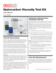
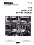
Small Diameter Filter Scavenger with Water Table Depression Pump Installation and Operation Manual Rev 05/28/2013 Part # 10441 TABLE OF CONTENTS Section 1: System Description …………………………..…………….………………………………… Function and Theory …………………………………………………………………………………. System Components ………………………………………………………………………………… Section 2: System Installation ……………………………..…………….………………………………. Section 3: System Operation …………………………………….……………………………………… Section 4: System Maintenance …………………………………………………………………………. Section 5: System Troubleshooting ……………………………..……………………………………… Section 6: System Specifications ……………………………………………………………………….. Section 7: Winch Assembly and Operation …………...............………….…………………………… Section 8: Replacement Parts and Accessories ……………………………………………………… Appendix A: Submersible Water Pumps …………….…………………………………………………. Appendix B: Decontamination Procedures ……………….……………………………………………. Warranty, Equipment Return, and Repair ……………………….……………………………….…….. 1 4 4 5 12 20 22 25 33 35 37 40 45 49 DOCUMENTATION CONVENTIONS This manual uses the following conventions to present information: An exclamation point icon indicates a WARNING of a situation or condition that could lead to personal injury or death. You should not proceed until you read and thoroughly understand the WARNING message. WARNING A raised hand icon indicates CAUTION information that relates to a situation or condition that could lead to equipment malfunction or damage. You should not proceed until you read and thoroughly understand the CAUTION message. CAUTION A note icon indicates NOTE information. Notes provide additional or supplementary information about an activity or concept. NOTE READ THE FOLLOWING CAUTIONS & SUGGESTIONS BEFORE PROCEEDING The Small Diameter Filter Scavenger (SDFS) is a sophisticated piece of equipment which must be installed, operated and maintained according to the procedures described in the system manual. Failure to follow these procedures or to observe the cautions included in this manual, may result in personal injury and will void the Standard Equipment Limited Warranty. Installation Do not deploy the SDFS until the well has been developed by qualified personnel. Silt and grit can damage the water pump and degrade its performance. Before deploying the system in the well, briefly test the water pump by turning the control switch to HAND. Do not run the water pump dry for more than 5 seconds at a time. Mount your GECM (or other control panel) under cover and in a location where it will never be submerged in water. All system wiring is to be carried out by a qualified electrician. For systems using a GECM or other control panel with an integrated Tankfull probe, the SDFS system will not run when the Tankfull probe is cut or disconnected. 2 Maintenance and Troubleshooting DISCONNECT POWER BEFORE OPENING ANY ENCLOSURE All maintenance and troubleshooting procedures must be carried out by qualified personnel only. Abraded or cut electrical cords should be replaced immediately. During system troubleshooting, attempt only the procedures outlined in Section 5 of the manual. Check the GECM control panel for accumulation of moisture. Whenever the pump/intake/probe assembly is removed from the well, clean the shafts on which the intake cartridge moves up and down. This will prevent fouling which could cause the cartridge to stick or bind. The optimal interval between cleaning will depend upon site-specific factors. If you require further assistance, please call Geotech at 800-833-7958 or (303) 320-4764. Figure 1 3 Section 1: System Description Function and Theory The Small Diameter Filter Scavenger (SDFS) is a hydrocarbon recovery system designed to operate in conjunction with a Water Table Depression Pump (WTDP). This combined product/water pumping system, built for either Product only or WTDP ready use, is available in 4” (10 cm) and 6” (15 cm) diameters. An extended travel model is also available. Figure 1-1 is an example of both units (the water pump and motor is not shown attached to the WTDP ready unit in this diagram). Figure 1-1 – Product Only and WTDP Ready SDFS Units. 4 When used with the Geotech Environmental Control Module (GECM), the standard SDFS system will consist of a downwell assembly that includes a product pump with product reservoir, a floating intake cartridge, a product/water probe (Reservoir probe), a Tankfull probe (optional), and a water pump (optional). Section 8 contains a breakdown diagram of a standard SDFS unit followed by a list of definitions and part numbers. An extended list of optional components is also included. Major system components are described on the following pages. SDFS are built for either Product only use or as WTDP ready (with water pump and motor). In either case, throughout the rest of this manual, the term SDFS will be used to describe the system in general. System Components Product Pump The Geotech product pump (with motor) is a magnetically coupled gear pump system that operates on 12VDC. The product pump turns on and off in response to signals sent to the GECM by a conductivity/density (reservoir) probe and a second separate Tankfull probe (these probes are described later in this section). A portion of the conductivity density probe is located inside the product reservoir. This probe has a shaft which extends to the top of the SDFS assembly, passing through the intake cartridge. The reservoir probe consists of HI and LO float actuated sensors inside the product reservoir. When the reservoir fills with product, the float rises, trips the HI sensor and turns on the product pump. When the product level falls, the float trips the LO sensor and shuts off the pump. A water override conductivity sensor is located inside the product reservoir at the base of the reservoir probe shaft. This sensor shuts down the product pump whenever water is detected inside the reservoir. The following chart represents a Gallons per Minute (GPM) per PSI (Pounds per Square Inch) average for the product pump. However, flow results can vary for a variety of reasons, i.e. new gear set, worn gear set, worn motor/bushings, line loss or low voltage to product pump motor. An example of the Product Pump performance curve is shown in Figure 1-2. PSI Range GPM/LPM Flow Rate Amps* Open flow .77 / 2.9 2.30 20 PSI (1.4 bar) .72 / 2.7 3.00 40 PSI (2.7 bar) .70 / 2.6 3.70 60 PSI (4 bar) .66 / 2.5 4.45 65 PSI (4.5 bar) (a functional product pump/motor will stay under 5 amps at 65 PSI / 4.5 bar) 80 PSI (5.5 bar) .61 / 2.3 5.10 100 PSI (6.9 bar) (a product pump/motor will decouple between 95 PSI and 105 PSI / 6.9 bar) *Test results were obtained using a Geotech Power Supply with an average output of 14.5VDC. The product pump is designed to decouple between 95 PSI (6.5 bar) and 105 PSI (7.2 bar) (or greater). 90 (6.2 bar) to 95 PSI (6.5 bar) is therefore the maximum pressure obtainable depending on the viscosity of the hydrocarbons being pumped. Factors that may reduce decoupling pressure (and therefore reduce maximum output pressure) include temperatures above 75°F (24°C), high fluid viscosities, abrasive fluids and pump wear. Once decoupling has occurred, the pump and motor can be recoupled by completely stopping and then restarting the unit. 5 Figure 1-2-1 – Product Pump performance curve (gallons per hour/PSI) Figure 1-2-2 – Product Pump performance curve (liters per hour/BAR) 6 Intake Cartridge The SDFS offers the advantage of a floating intake cartridge that follows the fluctuations of the water table. The intake float cartridge consists of a float with a specially treated oleophilic/hydrophobic screen. The screen is stainless steel with a PTFE coating and allows hydrocarbons to enter the cartridge while repelling water. The intake float cartridge is available in two mesh sizes - a standard 100 mesh for gasoline, kerosene, etc. and a coarser 60 mesh for hydrocarbons with viscosities between 100 – 400 SSU’s. The mesh sizes represent tradeoffs between oil flow and the ability to hold back water. The larger the hole sizes, the more easily oil flows through, but the more likely water is to enter the system. The 100 mesh screen has a blue coating while the 60 mesh is colored green. If the ground water contains any chemical that acts as a surfactant (amines, alcohols, sulfonate), reducing the surface tension of water, then some water will pass through the screen. When properly installed and operated, the system will reduce the thickness of hydrocarbon layers to 1/16 of an inch (1.6mm) or less. Should a water present alarm occur on the GECM, consider checking the function of the float screen or the condition of the ground water. The intake cartridge travels up and down a 1” x 36” water discharge pipe that also houses the electrical cable assembly supporting both the product and water pumps. The reservoir probe, product discharge tube and reservoir vent tube also pass through sleeved openings built into the intake cartridge. The SDFS design allows the cartridge 1’ (30cm) of working travel. Prior to installation the oleophilic/hydrophobic intake screen must be seasoned (or primed). To accomplish this use diesel, kerosene, or another similar hydrocarbon to saturate the screen portion of the intake. The optimum fluid would be the down well hydrocarbons to be recovered. Take care to avoid damaging the intake screen. Section 6 contains a graph on viscosity vs. temperature and the recovery rates of common hydrocarbons. A Hydrocarbon Viscosity Test Kit is also available from Geotech. The test kit can be used to evaluate the product being recovered to help you determine the best cartridge type to use. See Section 8 for part numbers to the Hydrocarbon Viscosity Test Kit User Manual and test kit, or contact Geotech at 303-320-4764 to discuss which cartridge is best suited for the product being recovered. Product Reservoir Attached to the intake cartridge is a flexible tube (guided by a pulley) that delivers product by gravity feed to a product reservoir positioned above the product pump. A float actuated switch inside the reservoir starts the product pump when the reservoir is full of product. Capacity of the reservoir is one quart (.95 liter). When the product pump is running, product flows from the reservoir down to the pump, up through the product discharge tube, and out through a flexible output hose to a recovery tank. The product reservoir is vented through a ¼” (6mm) stainless steel tube that extends from the reservoir to the top of the SDFS assembly. Attached to the vent tube is 4’ (122 cm) of 3/8” nylon hose which is capped with a breather element/debris screen. When placing the SDFS into the well, do not allow the vent tube to be submerged or the unit could “vapor lock” during operation. 7 Reservoir (Product/Water) Probe The product pump and water pump cycle on and off in response to signals sent to the GECM via float actuated HI and LO reed switches built into the reservoir probe shaft (as shown in Figure 5-2). A separate conductivity actuated sensor disables the product pump if water is detected in the reservoir. An installed reservoir probe runs the length of the SDFS unit, from the inside bottom of the product reservoir, to the top of the assembly. The water present sensor and switches controlling the product pump are located within the part of the probe shaft placed inside the reservoir. The portion of the probe shaft that extends above the reservoir houses the switches that control the water pump and water override. These float actuated switches are tripped by magnets embedded within the intake float cartridge, the water float (orange), and the product float (blue) as they move up and down the reservoir probe shaft. All probe wiring is rated Intrinsically Safe for Class 1, Div. 1, Group D hazardous locations. Water Pump A set of HI and LO sensors are located along the upper part of the reservoir probe shaft. These sensors are placed near the top and bottom limits of the intake cartridge travel and indicate the cartridge position during installation and operation. When the cartridge level becomes too high, a signal is sent to the GECM to turn on the water pump. The water pump (for WTDP ready systems) will automatically lower the cone of depression in the well and shut off when the intake cartridge reaches the lower sensor. This function keeps the intake cartridge travel as close to the product layer as possible. However, it may be necessary to re-adjust the SDFS position within the well also. Water pumps are available with 2-wire or 3-wire motors and range in power from 1/3 to 20 horsepower. 2-wire motors are available in single phase only and feature built-in start components and thermal overload protection. 3wire motors (through 1HP) include built-in thermal overload protection. 3 phase, deep well submersible pump motors, which require an external start component, can come with either an external start box or designated motor starter (installed within the GECM). Start boxes and motor starters are supplied by Geotech as an option. Most motor/pump scenarios, including multiple pumps, can be controlled by one GECM with the appropriate motor starter(s) installed. Refer to Appendix A for a list of water pumps available from Geotech. SDFS Accessories The following accessories must be ordered separately from the basic SDFS system. Refer to Section 8 of this manual for a listing of available accessories for your SDFS system. 8 Tankfull Probe When attached to the optional GECM control panel, the Tankfull probe is used to shut off the product pump when the product recovery tank becomes full. The Tankfull probe (Figure 1-3), containing a float actuated level switch, is installed in the top of the recovery tank. As a safety measure, systems with an integrated Tankfull probe will also shut down when the probe is disconnected or the cable is cut. All probe wiring is rated Intrinsically Safe for Class 1, Div. 1, Group D hazardous locations. Figure 1-3 – Tankfull Probe Assembly 9 Junction Boxes To facilitate the wiring of the SDFS system, Geotech offers ready to install power and signal junction boxes (Figure 1-4). The optional junction boxes contain terminal strips that allow the SDFS cable assembly and the reservoir probe cable to be joined to customer installed, conduit enclosed wire runs from the well head. Explosion proof junction boxes can be provided (as shown in Figure 1-4, items A and C) or terminal connections can be housed within a NEMA 4 junction box (item B). Figure 2-1 contains a generic example of a common site installation, showing power and signal junction box placement. Figure 1-4 – Junction boxes available for use with the SDFS system. (A) Explosion proof power junction box. (B) NEMA 4 signal junction box. (C) Explosion proof junction box with receptacle. Refer to the Section 8 for part numbers. Product Pump 12VDC Power Supply Power Supply’s are used to operate the 12VDC product pump motors built into the SDFS system. A 115VAC or 230VAC Power Supply is available from Geotech. Power requirements are dependent on either the main power or an installed transformer within the GECM. A Power Supply is designed to receive two power leads from the GECM; HOT and NEUTRAL for 115VAC, or two HOT leads for single phase 230VAC. The voltage is then converted to 12VDC (with an average output of 14.5VDC) for product pump operation. Figure 1-5 shows an example of a 230VAC to 12VDC Power Supply panel. 10 Each panel comes housed in a NEMA 4 enclosure with labeled terminal strips. A wiring diagram can be found on the inside cover of the enclosure. Power Supplies should be installed as near to the well as possible to reduce DC line loss between it and the product pump. Two AC power wires will then run from a relay or terminal strip within the GECM to terminal strip TB1 on the Power Supply panel. Single phase motors can be wired through the Power Supply box or directly to a motor starter within the GECM. Three phase water pump motors are wired directly to a designated motor starter within the GECM, bypassing the Power Supply. Figure 1-5 – Example of the components to a 230VAC to 12VDC power supply. Hoses 100’ (30m) of 3/8” nylon hose (for attachment to the discharge tube fitting) is provided with the SDFS system. Additional discharge hoses and fittings supporting both product and water pump use can be obtained from Geotech also. Additional Accessories A variety of options and accessories are available for the SDFS system, including globe valves and flow meters. If debris in the well is a concern, then consider fitting your unit with a protective well shroud. Refer to Section 8, Replacement Parts and Accessories, for a list of parts. Additional accessories can be found in the Geotech catalog. 11 Section 2: System Installation The SDFS system must be installed, operated and maintained according to the procedures described in this manual. Failure to follow these procedures, or to observe the Warnings and Cautions included in this manual, may result in personal injury and will void the Standard Equipment Limited Warranty. Do not deploy any pumps until the well has been developed by qualified personnel. Excessive silt and grit can clog the intake float cartridge or damage the water pump, degrading their performance. Never run the product or water pump dry for more than 5 seconds at a time. Position the water pump so that the intake is no closer than 1’ (30cm) from the bottom of the well. Inspection Inspect the SDFS unit and accessories upon arrival. If any items are missing or damaged, make note of this on the shipping papers and immediately notify your Sales Representative at Geotech. Also, in preparation for installation, remove any shipping straps and cable ties from around the intake float cartridge prior to deployment. System Wiring Throughout the wiring procedures described below, refer to the site installation drawing in Figure 2-1, the various wiring diagrams within this section, and to the separate Field Wiring Diagram provided with your GECM control panel. All wiring must be carried out by a qualified electrician and be in accordance with the state and local codes. Conduit runs must conform to Article 501-5 of the 1990 National Electrical Code (NEC). Install GECM In preparation for installation, mount the GECM control module under cover to protect the unit from the elements. Power must be disconnected and locked out at the panel or services before any installation procedures are attempted. Wiring Product and Water Pump Connections The SDFS system can be ordered with a variety of Grundfos water pumps attached. These pumps are operated with single and three phase motors. Product pumps are available only in 12VDC and are built and installed internally to the SDFS by Geotech. If applicable, refer to the GECM Field Wiring Diagram and to the wiring diagrams on the following pages for installation and wiring instructions specific to your system. Do not run any power wires within 2 inches (5 cm) of intrinsically safe (IS) wires or terminals. Reference NEC Article 508 for relevant codes. When wiring to a GECM control panel run the pump power wires through the bottom of the enclosure and attach them to the WATER PUMP and PRODUCT PUMP POWER OUT terminals. Attach the ground wire to the chassis grounding lug next to the terminal block. Check tightness of terminal screws. 12 Figure 2-1 – A WTDP ready SDFS deployed with the optional GECM, power supply, Tankfull probe, and explosion proof accessories. Wiring a Single Phase 115 or 230VAC SDFS with Water Pump and 12VDC Product Pump Motors Wire the water pump motor leads for a single phase, 115 or 230VAC motor through a wellhead junction box (optional) and attach the leads to labeled terminal strip TB2 within a 115 or 230VAC Power Supply. Single phase motor leads from a WTDP ready SDFS will be black, red, and yellow (ground) and will be connected color for color to positions 1, 2, and 3 on TB2. Wire the GECM to the Power Supply by attaching a pair of HOT leads to positions 1 and 2 on TB1 (AC power to be converted to 12VDC for the product pump), and a pair of HOT leads to positions 3 and 4 on TB1 (115 or 230VAC single phase power to run the water pump motor). These leads will generally come from labeled relays or terminal strips built onto the back panel of the GECM. Attach a ground wire from a designated ground lug to position 5 on TB1 (yellow/ground). Figures 2-2 and 2-3 are examples of 115 and 230VAC WTDP ready SDFS wiring diagrams. Terminal positions are labeled on all GECM back panels and on all Power Supply panels provided by Geotech. See the GECM Field Wiring Diagram and the Power Supply diagram for additional wiring instructions. Alternatively, the water pump power leads can also be run directly to a separate motor starter within the GECM, bypassing the Power Supply enclosure all together. 13 Figure 2-2 – Wiring the 115VAC 2-Wire Water Pump and the 12VDC Product Pump Motors. Figure 2-3 – Wiring the 230VAC 2-Wire Water Pump and the 12VDC Product Pump Motors 14 Wiring a Three Phase SDFS with Water Pump and 12VDC Product Pump Motors Wire the water pump motor leads for a three phase, 230VAC motor through a wellhead junction box (optional) and attach the leads to T1, T2 and T3 of an appropriate start box or to a motor starter labeled WTDP within the GECM. Wire the GECM to a 230VAC Power Supply by attaching a pair of HOT leads to positions 1 and 2 on TB1 (AC power to be converted to 12VDC for the product pump). These leads will generally come from a labeled relay or terminal strip built onto the back panel of the GECM. Figure 2-4 shows an example of a 230VAC three phase WTDP ready SDFS wiring diagram. Terminal positions are labeled on all GECM back panels and on all Power Supply panels provided by Geotech. See the GECM Field Wiring Diagram and the Power Supply diagram for additional wiring instructions. An 115VAC Power Supply can also be used if the GECM has an appropriate transformer installed. Figure 2-4 – Wiring the 3-Phase Water Pump and the 12VDC Product Pump Motors. 15 Wiring a 12VDC Product Pump (w/o Water Pump) Wire the product pump motor leads from a SDFS system through a wellhead junction box (optional) and attach the leads to positions 4 (blue/common) and 5 (orange/ground) on terminal strip TB2 within a 115 or 230VAC Power Supply enclosure. Wire the GECM to the Power Supply by attaching a pair of HOT leads to positions 1 and 2 on TB1 (AC power to be converted to 12VDC for the product pump). These leads will generally come from labeled relays or terminal strips built onto the back panel of the GECM. Attach a ground wire from a designated ground lug to position 5 on TB1 (yellow/ground). Figure 2-5 shows an example of a 115VAC SDFS wiring diagram for a product pump only. Figure 2-5 – Wiring for Product Only pump motor. 16 Wire Reservoir (Product/Water) Probe The product pump and water pump cycle on and off in response to signals sent to the GECM by float actuated HI and LO switches built into specific points within the reservoir probe shaft. A separate conductivity actuated sensor disables the product pump if water is detected in the reservoir. Run the reservoir probe cable through a wellhead junction box (optional) and then to the GECM. Run the cable through an access port on the upper side of the enclosure and attach the leads to a designated IS terminal strip on the GECM PCB (as shown in the GECM Field Wiring Diagram). Figure 2-6 shows the circuitry for the reservoir probe. Do not use the orange and green wires when wiring in a Product Only system. Do not place the reservoir probe cable near any power wires. Figure 2-6 – Reservoir Probe Wiring Diagram with Switch and Sensor Positions. 17 Wire Tankfull Probe After mounting the Tankfull probe in the product recovery tank attach the probe connector to the Tankfull receptacle on the side of the GECM enclosure. If the Tankfull probe does not have a connector attached then use the GECM Field Wiring Diagram to connect the wire ends to the internal PCB. Figure 2-7 shows the circuitry for the Tankfull probe. Figure 2-7 – Wiring a Tankfull probe to the GECM control panel. 18 System Pre-check Before deploying a SDFS system into the well, carry out the following unit preparation procedures. On Product Only Systems Fill the pump water jacket with clean water by turning the SDFS assembly upside down and removing the plug at the bottom of the unit’s water jacket. Take care not to damage the intake float cartridge. Check all wiring. On product only applications the orange and green wires will not be wired to the GECM. For WTDP ready SDFS, verify exposed wiring to the water pump/motor are zip tied and out of the way from catching on the walls of the well. System Deployment 1. Attach a winch cable to the cable at the top of the SDFS system and carefully lower the assembly into the well. As you place the unit into position, ensure that the water pump intake (WTDP applications) is no closer than 1’ (30cm) from the bottom of the well. This will prevent debris from entering the pump intake which can cause premature wear to the pump impellers. Under no condition should a SDFS system be suspended down well by its power cord or discharge hoses. 2. Confirm that the output hose of the water pump is connected to suitable collection point or proper runoff. Check local regulations. 3. Run the 3/8” nylon product discharge hose to the product recovery tank. 4. Apply power to the GECM. Set both the product and water pumps to OFF. This will allow you to watch the control panel display for float positions. 5. Adjust the position of the SDFS assembly in the well until the intake float is suspended in product and is at the midpoint of its travel. The GECM display will show “H2OM ORH” with the intake cartridge at midpoint. To confirm that the intake cartridge is at the midpoint of its travel, lower the unit until H2OH is received, then raise the unit approximately 6” (15 cm), or until the display changes to H2OM. 6. Observe the probe status for water and product levels on the GECM display. Refer to the GECM User Manual for display definitions. You may need to run the water pump in HAND until a stable “cone of depression” within the water table has been established. When the pump assembly passes through the hydrocarbon/water interface, fluid displacement will artificially raise the level of the interface in the well. This condition can persist for up to 48 hours depending upon the permeability of the earth surrounding the well. Readjustment of the SDFS system level as a whole may be required. 19 Section 3: System Operation System Startup Before starting the pump, read your GECM control panel manual and become thoroughly familiar with all panel controls and indicators. Proceed as follows to start the system. 1. Open the water pump discharge valve completely by turning it counter-clockwise. 2. With the PRODUCT and WATER PUMP CONTROL switches in the OFF position, turn the WATER PUMP CONTROL switch to AUTO. 3. The water pump should start and begin cycling on and off as the water level rises and falls in the well. The water pump side of the system should be purged if free hydrocarbon is present in the well at deployment. To do this, place the output hose in a suitable container and run the pump on HAND until the water runs clear. Dispose of purged hydrocarbon according to local codes. 4. With the water pump running on AUTO, establish a pumping level and throttle down the outflow by adjusting the discharge valve. Reduce the rate of pump cycling as far as possible without going below the minimum flow rate recommended by the pump’s manufacturer. Ideally, the pump should be “valved” to approach continuous operation while maintaining the desired level of drawdown. 5. Adjust the position of the downwell assembly as explained in Section 2. 6. Start the product pump by turning the PRODUCT PUMP switch to AUTO. Once startup has been achieved, the PSCAV system should function automatically. Refer to the GECM User Manual for details of control panel operation. GECM Display Messages for the SDFS The following display messages are common to the operation of a WTDP ready SDFS system. SDFS Displays – Line 1 messages: HAND:Px H2Ox ORx AUTO:Px H2Ox ORx AUTO: TANKFULL AUTO: H2O IN RES AUTO: OVERRIDE AUTO:PROBE FAULT (condition) (fault) (fault) (fault) Line 2 messages: PROD nnn H2O nnn Where x = H (high), M (middle), or L (low) nnn = ON or OFF 20 Multiple SDFS Systems Line 1 messages: SDFS SYSTEM # SDFS#: TANKFULL SDFS#:H2O IN RES SDFS#: OVERRIDE SDFS#:PROBEFAULT (condition) (fault) (fault) (fault) Line 2 messages: PROD nnn H2O nnn Where # = 1, 2, 3 or 4 (SDFS number) nnn = ON or OFF Additional Messages for Multiple SDFS Systems: SDFS#: LEVELS OVERRIDE (fault) SDFS#: LEVELS PROBE FAULT (fault) SDFS#: LEVELS Px H2Ox ORx Where # = 1, 2, 3 or 4 (SDFS number) x = H (high), M (middle), or L (low) 21 Section 4: System Maintenance It is recommended that your service technicians schedule training at our Denver location prior to servicing a SDFS system. The replacement of a major SDFS component, such as the product pump, reservoir probe, or intake cartridge, can easily put the SDFS unit out of calibration if any one part is not installed accurately. See your local Geotech Sales Representative for additional information on service or training on our equipment. Clean Intake Cartridge The floating intake cartridge is the heart of the SDFS system. Therefore, the intake cartridge (oleophilic/hydrophobic screen, float, float shaft, flexible intake hose and pulley-counterweight) should receive periodic thorough inspections. The floating height of the intake screen is minimal. Once primed, the cartridge will not pass water unless: (1) the intake cartridge has risen to the top of its travel allowing water to rise above the top of the cartridge (thus indicating that the system should be raised to a height at which the intake is floating within its 1’ (30 cm) of working travel, especially so with Product Only units), (2) an inordinate amount of debris is allowed to build up on the surface of the screen, (3) a detergent (surfactant) contacts the screen (a detergent will “wet” the screen and allow water to pass), and (4) there is little to no product in the well, eventually allowing water to pass. If the screen is found to be clogged with debris or has been submerged in water, a gentle rinsing in kerosene or gasoline is recommended. When the presence of detergents is suspected, samples should be taken and tested. The oleophilic/hydrophobic screen will not be effective in detergents, and in such cases, use of a Geotech Small Diameter Probe Scavenger should be considered. If there is no free phase product in the well, a thin film of petroleum jelly can be applied to the screen to keep water from passing through. Since the SDFS assembly must be removed from the well to perform maintenance on the intake screen, such occasions should be used to carry out a general inspection of the entire assembly. It is particularly important that the flexible product hose be carefully checked. This hose should be replaced if leaks or major kinks are discovered. Product Reservoir Probe The product reservoir probe contains a conductance actuated water sensor (water override) which will sense as little as ¾” (1.9 cm) of water in the bottom of the reservoir. When water is detected, the GECM will display “H2O IN RES” and the product pump will be prevented from running in the AUTO position. In this event, the selector switch can be turned to the HAND position (for 10 seconds at a time) to pump the water out of the reservoir. DO NOT RUN THE PUMP ON HAND FOR A LONGER PERIOD OF TIME AS THIS MAY RUN THE PUMP DRY AND CAUSE DAMAGE. If the water sensor continues to sense water in the product reservoir, a problem with the intake cartridge or faulty check valve are possible. Clean Tankfull Probe It is essential that the probe shaft and float be cleaned on a regular basis. Use phosphate free detergent, warm water and a soft brush. The required frequency of cleanings is highly site specific and must be determined by the user. Failure to clean the probe will result in fouling that could cause system malfunction and overflow of product. Ensure the float is re-installed correctly since the probe is magnetically activated. Backup Check Valve It is recommended that an alternate check valve be installed in the event of a primary check valve failure. Installation can be carried out without removing the downwell pump assembly from the well. The backup check valve will consist of a white Acetal valve, two stainless steel reducer bushings and two brass compression fittings. This specific valve is not interchangeable with the check valve installed on the unit and is mounted as a back up only. Contact your Geotech Sales Representative for these parts when a backup check valve is needed. 22 To install the check valve: 1. 2. 3. 4. 5. Cut the nylon discharge line at a convenient accessible location next to the well head. Thread the stainless steel reducer bushing into the valve ends using PTFE tape on all male threads. Orient the valve so that the arrow points in the direction of fluid flow. Thread the compression fittings into the reducer bushing using PTFE tape. Slip the cut ends of the discharge line into the compression fittings and tighten. Figure 4-1 – Parts configuration for a back up Acetal check valve. Water Pump Maintenance Following is a schedule of recommended water pump maintenance. Water Table Depression Pump System Frequency of Maintenance Tasks / Quarterly Calendar Week Task 1 2 3 4 5 6 7 8 9 10 11 12 Check flow rate to ensure minimum cycling frequency ● ● ● ● ● ● ● ● ● ● ● ● Remove cover from probe and clean floats/conductivity sensors ● ● ● ● ● ● ● ● ● ● ● ● Check start box for moisture accumulation Take current draw readings and compare with motor specification ● ● ● Inspect hoses and wires for cracks, cuts, and abrasions ● ● ● ● ● ● ● 23 SDFS Well Shroud To protect the intake cartridge from damage and to keep floating debris out of the intake cartridge and pulley travel, a PVC well shroud (Figure 4-2) can be attached to the SDFS unit prior to well deployment. The well shroud is secured to the SDFS with stainless steel screws (provided). Contact your Geotech Sales Representative to add this accessory to your unit. Figure 4-2 – SDFS Well Shroud 24 Section 5: System Troubleshooting These procedures are meant to be carried out by personnel qualified to work on electrical circuitry. If in doubt, obtain the services of a qualified electrician. Getting Help If the troubleshooting procedures in this section indicate a component failure, call Geotech Environmental Equipment after documenting the problem as outlined below. Read the entire manual and become thoroughly familiar with all system components and troubleshooting procedures. Prepare a written list of all problems encountered while operating the equipment. Service Locations Geotech Field Service personnel are trained on all aspects of the equipment and are dedicated to helping you maximize the efficiency and cost effectiveness of your PSCAV system. For technical support call our Geotech Service office. Geotech Environmental Equipment, Inc. th 2650 East 40 Avenue Denver, CO 80205 Toll Free Phone: (800) 833-7958 Commercial Phone: (303) 320-4764 Fax: (303) 322-7242 www.geotechenv.com TROUBLESHOOTING PROCEDURES In the process of troubleshooting, it may be necessary to open the GECM control panel. In such cases, always disconnect the power before proceeding. Avoid shorting any power to the PCB or PCB cover. Since all probe wiring is rated Intrinsically Safe, probe connectors may be disconnected from their receptacles without disconnecting the power. Troubleshooting the SDFS is primarily a matter of checking the function of the intake cartridge and the probes. The GECM is designed to be maintenance free. The water pump/motor is factory sealed with no field replaceable parts. Before proceeding with this section refer to the troubleshooting section of your GECM manual. Possible malfunctions are listed as follows: 25 Problem: Water pump running but no water delivered Cause: 1. 2. 3. 4. 5. Discharge valve closed. Discharge hose kinked or blocked. Pump motor running backwards (3 phase motors only). Debris clogging intake. Cut wire. Remedy: 1. 2. 3. 4. Open valve. Locate blockage and clear. Reverse any two legs at the connection between the pump power cord and the control panel. Pull unit and inspect all wiring. Problem: Product pump will not run on AUTO, runs dry on HAND Cause: These symptoms indicate that the intake float cartridge is neither accumulating product nor water. Remedy: 1. Verify that the intake float cartridge is not stuck above the product/water interface. If the shafts that run through the intake float become fouled or bent, the float may hang up as the water level in the well falls. In the event of a stuck float, gently shake the pump assembly up and down in the well. If this does not free the float, the assembly must be withdrawn from the well for inspection and cleaning. If needed, refer to Section 4 for intake cartridge removal and replacement procedures. 2. Confirm that the product layer is not too thin. When in the process of its normal operation, the intake float cartridge has skimmed the product layer down to approximately 1/16 of an inch (1.66mm) or less, a point will be reached when no further product can be collected. This condition should be suspected when tests reveal that the intake float cartridge is not stuck yet still picks up no product. Pull the pump assembly from the well and check the thickness of the product layer with a Geotech Interface Probe. At this time, inspect the intake float cartridge screen and clean if necessary. 3. Verify that the vent tube has not been completely submerged/flooded within the well. If there is any fluid in the vent tube line, the system will “vapor lock” and product will be kept from entering the reservoir. 26 Problem: Pump will not run on HAND or AUTO Remedy: 1. Confirm that power is reaching the GECM or other control panel. 2. If power is reaching the GECM, then check for a faulty Tankfull probe by unplugging its connector at the GECM and jumpering between receptacle sockets A and B. If the pump runs on HAND with the Tankfull disconnected, then the problem is most likely a faulty Tankfull probe or cable. 3. It is also possible that the recovery tank is just full, or that the float on the probe has been re-installed upside down after being cleaned. 4. If the problem is not in the GECM or Tankfull probe, then a faulty product pump/motor or cord should be suspected. Remove the pump assembly from the well, move it and the GECM to a non hazardous location and check the pump operation and its power cord. A faulty product pump/motor should be replaced. If the pump will not run after carrying out these procedures, the wiring or the pump motor itself may require repair or replacement. Call your Geotech Sales Representative for assistance. Problem: Pump produces product on HAND but does not run on AUTO Cause: The most likely source of trouble in the AUTO mode is a reservoir probe circuit fault, a stuck float, or a bad connection at the wellhead junction box. Remedies: 1. Use a continuity meter to check connections at the terminal strip inside the wellhead junction box. If no faulty connections are found, proceed as follows to determine if the probe fault is in the reservoir probe or in the GECM’s control circuitry. 2. Inspect all floats on the unit. Verify that they can travel freely on the probe. 3. Check for problem with the Product Reservoir Probe (GECM panels with 8 and 10 pin connectors) Disconnect the probe cable connector from its receptacle and use a thin wire to jumper the following pins. For example, with a D to F jumper in place, running a second jumper from J to F simulates the situation when the reservoir float is at the top of its travel (reservoir full). If the pump turns on with these jumpers in place, then the problem is probably a stuck reservoir float. To determine if the reservoir float is indeed stuck, use an ohm meter to check resistance between the pins (wires) of the probe cable connector. A reading of approximately 12 ohms indicates that the float is off the bottom. Now operate the pump on HAND. If resistance does not go from approximately 12 ohms to open, the float is stuck above its low position. In any case, if it is found that a stuck float is the problem, the SDFS assembly will have to be withdrawn from the well and the probe removed for recalibration or replacement. 4. Check for problem with the Water Override Sensor Run the pump briefly on HAND to clear any water from the product reservoir. If the pump still will not run on AUTO, and there is still water present (on the GECM display), then either the water override sensor is shorted to the reservoir body or water is leaking rapidly into the reservoir due to a leaking check valve or cartridge failure. In either case, the SDFS assembly will have to be removed from the well for repairs. The check valve can be disassembled for cleaning if it appears not to be seating properly. 27 PROBE RECEPTACLE CONNECTIONS Probe conditions may be simulated by jumpering pairs of contacts in the probe connector mounted on the GECM control panel. Listed below are jumper simulations for the probes used with the SDFS system. To make the necessary connections, use a piece of thin, insulated wire as a jumper and insert its ends into the indicated pin receptacles. Reservoir probe designator A B C D E F G H J K Probe wire color white black yellow blue orange red (not used) green brown violet JUMPER CONNECTIONS SDFS Reservoir Probe D–F Simulates that the reservoir product float is up from the bottom stop (acts as a latching circuit to completely pump out the reservoir.) J–F Simulates reservoir float at top of travel (product high). This signals the product pump to turn on. The J – F connection can then be broken and the pump will stay on until the D – F connection is broken. K – Ground Simulates water in the product reservoir. This condition will show “H2O IN RES” on the GECM display and will shut down the product pump. Figure 5-1 – 10 pin Reservoir Probe receptacle. 28 SDFS Reservoir Probe Cable Connector Pin Connections The actual status of the reservoir probe may be checked by using an ohm meter to measure resistances from pin to pin. A normally closed switch will give a resistance reading of approximately 12 -13 ohms unless the float magnet is holding the switch open. Similarly, a normally open switch will give an open reading unless the float magnet is holding the switch closed. Probe Connections D–F Product low switch inside the reservoir (Normally Closed). Held open when product float is at low position. J–F Product high switch inside the reservoir (Normally Open). Closed when product float is at high position. B–C Low switch at bottom of floating Intake Cartridge travel (Normally Closed). Held open when intake float is at low position. A–C High switch at top of floating Intake Cartridge travel (Normally Open). Closed when intake float is at high position. E–H Water override switch (Normally Closed). Held open when water float is at high position. K – GROUND This is a connection made through water between K (an insulated stainless steel tube inside the product reservoir) and Ground (the reservoir body). This connection cannot be measured unless product reservoir is filled with water. The following figures show the locations of the SDFS floats, probe switches, and sensor. 29 Figure 5-2 – SDFS switch and water sensor locations. 30 Figure 5-3 – Locations of switches and water sensor within the SDFS reservoir. 31 Tankfull Probe The following applies to control panels with a Tankfull receptacle. As a safety measure, systems with an integrated Tankfull probe will shut down when the probe is disconnected or the cable is cut. A–B Normally Closed connection. Simulates that the Tankfull float is down. Pump will run. Removing the A – B jumper connection will simulate a Tankfull float up. Shuts pump off. One common problem with the Tankfull probe not working is the float being installed upside down after cleaning. Figure 5-4 – 8 pin Tankfull Probe receptacle. 32 Section 6: System Specifications Figure 6-1 - Viscosity chart and temperature 33 New SDFS Specification Sheet System Type: ____ Product Only ____ WTDP Ready ____ 4” ____6” WTDP Power Requirements: ____ Voltage ____ Phase ____ HP ____ Hz Intake Float Cartridge: ____ 100 mesh ____ 60 mesh Power Supply: Y / N ____ 120V ____ 230V Winch Assembly: Y/ N ____ Standard ____ Heavy Duty Cable / Hose Lengths: Power Cord Length: ______ ft./m Discharge tubing length: ______ ft./m ____ Product Only Well Shroud: Y/ N Serial No. _______________________ P.I.D. _______________________ Inspected by: _______________________ 34 ____ WTDP Ready Section 7: Winch Assembly and Operation Winch assemblies are available for the SDFS system. Mount the winch on the well casing as shown in Figure 7-1. Attach the winch cable to the lift cable on the unit. Carefully lower the unit into the well and suspend at the desired level. The cable on a standard winch has a rated breaking strength of 2000 lb. (907 kg) using the recommended design ratio of 1 to 5. The rated break strength gives a maximum hanging weight of 400 lb. (181 kg). Because each application is different, it is impossible for Geotech to anticipate the exact hanging weight of your system. Hanging weight is the sum of pump weight, the weight of all discharge piping, and the weight of any water trapped inside the piping. Although it is unlikely that you will exceed the 400 lb. (181 kg) maximum, Geotech highly recommends that you take the time to calculate the hanging weight of your system before deployment. Use the following procedure to calculate hanging weight. 1. Weigh your pump assembly, including the intake and any attached probes. 2. The weight of the discharge piping can be calculated by weighing a sample length and multiplying by the number of feet suspended in the well. For example, 1.5” ID rubber hose weighs approximately 1 lb. (.45 kg) per foot (.3 m) . Therefore, 100’ (30 m) of this hose will weigh 100 lbs. (45 kg). 3. The weight of the water in the discharge piping can be estimated by calculating the volume of water in the piping and then converting the volume to weight as follows: Volume in gallons Volume (in³) = x [inside radius of pipe (in)]² x [length of pipe (in)] Gallons = 0.00433 x Volume (in³) 1 Gallon (water) = 8.325 lbs Weight of Water (lbs) = 8.325 x Gallons Volume in liters Volume (cm³) = x [inside radius of pipe (cm)]² x [length of pipe (cm)] Liters = 0.001 x Volume (cm³) 1 Liter (water) = 1 kg Weight of Water (kg) = Total number Liters 4. Find the sum of the pump weight, piping weight, and water weight. This sum will provide a close approximation of the total hanging weight. If the total hanging weight approaches or exceeds 400 lbs. (181 kg), then contact Geotech to discuss an optional winch cable with an increased break strength rating. 35 Figure 7-1 – Standard winch assembly attached to well head. 36 Section 8: Replacement Parts and Accessories Figure 8-1 – SDFS (Small Diameter Filter Scavenger) System with Water Pump (WTDP Ready) 37 Item # Parts Description 4" SDFS 1 2 2 3 4 5 5 6 7 8 9 10 11 12 13 14 15 ORS689001 2104100 2104101 2290008 2290010 2290401 2998737-17 ORS754008 2290006 2010037 2020102 2020101 ORS758002 ORS755002 PPF057020 PPP019002 PPP001057 16 17 18 19 20 21 25 26 27 28 29 34 34 35 38 39 42 43 44 45 49 50 51 52 53 54 55 56 57 58 59 60 61 62 63 64 65 WATER JACKET,SS,16",WTDP READY ASSY,CABLE,PRODUCT PUMP 100' FIELD REPLACEABLE ASSY,CABLE,WTDP 100' FIELD REPLACEABLE RESERVOIR ASSEMBLY PULLEY ASSEMBLY FLOAT CARTRIDGE,ASSY,100MESH4" FLOAT CARTRIDGE,ASSY,60MESH4" HOUSING,BREATHER,VENT TUBE RESERVOIR PROBE ASSY 100FT CABLE COLLAR,SHAFT,.25"DIA PRODUCT FLOAT ASSY,SM DIA ASSY,WATER FLOAT,SM DIA WELDMENT,CABLE EXIT SDFS DISC,CTRG,BOT,DEL,4 SDFS CLAMP,WORM DR,.62"-1.25" CMPRSN,BRS,3/8x1/4MPT HOSE, TYGON F-4040-A,1/8 ID X 1/4 OD HOSE, TYGON F-4040-A, 1/4 ID X 3/8 OD, 1/16 WALL COLLAR,SHAFT,.375"DIA TUBING,SS4,.37ODx37.37 CMPRSN UNION,BRS,3/8" LIFT COUPLING,SDFS SCREW,SS8,10-32x5/8",PNH STRAIN RELIEF,NYL,3/4"NPT CABLE,SS,3/16",NYLON JKT CLAMP,GALV,CABLE,3/16" DISC,CTRG,TOP,DEL,4 SDFS BUSHING,SS,.75x.25",SQ HEAD CMPRSN,SS6,1/4X1/4MPT,BORED THRU,VITON O-RING NIPPLE,SS,1"xCLOSE NIPPLE,SS,1"x3" QDISC,BRS,1"Mx1"FNPT CONN,2 PIN,CONNECTOR KIT FRANKLIN CONN,3 PIN,KIT MOT LEADS STRAIN RELIEF,.090-.265 CBL CONN,PWR,3/4"NPT,.312-.437 STRAIN RELIF CAP,AL,QDISC,1" CAP,PROTECTOR,3 PIN,CONN,SDFS SPRING,EXT,7/16"x.041"x20" SCREW,SS8,8-32x.25",PNH SCREEN,CUP,60M,.3DIAMx.5LONG UNCOATED NUT,HEX,SST,3/8-16 BOLT,NYL,3/8-16x.75",VENT TUBING,SS4,.375ODx1.625 WEIGHT,SS4,.75DIAx.5 NUT,HEX,NYL,10-32 DISC,NYL,PROBE CENTERING SCREW,SS8,6-32x.25",SET CMPRSN,BRS,3/8x1/4MPT HOSE,NYL,.375"OD,.05"WALL CMPRSN UNION,BRS,3/8x1/4 TUBING,SS4,.25ODx39.75 PRODUCT PUMP MOTOR ASSEMBLY CONN,2 PIN FOR PRODUCT CABLE ASSY,MALE COUPLING,SS4,1.5"x1" BAR STOCK ONLY 66 See Appendix A for available water pumps 38 6" SDFS 2290601 2290661 ORS755001 PPP019015 PPP001058 PPM109002 ORS090010 PPP053015 2290016 PPF037008 10519 PPM075001 PPM082001 ORS755003 ORS756004 PPP019008 PPP009017 PPP009093 PPP007041 10264 10807 PPM003003 PPE019007 PPP010005 ORS641002 PPM071011 PPF036006 ORS759009 PPF043001 ORS759008 ORS090008 ORS759002 PPF023002 ORS771003 PPF039006 PPP019002 PPP001051 PPP053017 ORS095021 2020104 PPE005040 PPP021036 ORS755004 Additional Parts and Accessories Parts Description Parts List POWER SUPPLY,115V 12V SITEPRO POWER SUPPLY,230V 12V SITEPRO 2391055 2392055 ASSY,WINCH,STD DUTY,71FT 1000LB MAX ASSY,WINCH,HEAVY DUTY,110FT 2500LB MAX 2020005 2030001 SHROUD,PVC40,4”X48”,SDFS SHROUD,PVC40,6”X48”,SDFS ORS762001 ORS762002 PLUG,SS4,1"MPT JB,SITEPRO SGNL JB,SITEPRO XP POWER RECEPTACLE ASSY,115V,EP POWER RECEPTACLE ASSY,230V,EP PPP038005 2390065 2390066 1011907 1022903 KIT,GEAR SET,MP,KEVLAR PRODUCT PUMP KIT,GEAR SET,MP,POLYAMIDE PRODUCT PUMP 16100001 16100002 TANKFULL PROBE,25’,NO CONN TANKFULL PROBE,2005 PROBE ASSY,SD,SITEPRO,50’ 2390073 56020009 2390056 SPARE PARTS BAG,115V,4"SDFS SPARE PARTS BAG,230V,4"SDFS SPARE PARTS BAG,115V,6"SDFS SPARE PARTS BAG,230V,6"SDFS 2290019 2290020 2290021 2290022 MANUAL,SD FILTER SCAVENGER WTDP READY MANUAL,TEST KIT,HYDROCARBON VISCOSITY TEST KIT,HYDROCARBON VISCOSITY SDFS HANDHELD INDICATOR 10441 26030020 86020001 86100009 39 Appendix A: Submersible Water Pumps Refer to the installation and operation manual included with your pump and motor. The following pages will include cable and motor specifications as well as start box schematics. Two or Three Wire Cable, 60 Hz (Service Entrance to Motor – Maximum Length in Feet) Motor Rating AWG Copper Wire Size Volts HP 14 12 10 8 6 4 3 2 1 0 00 000 0000 115 1/3 130 210 340 540 840 1300 1610 1960 2390 2910 3540 4210 5060 1/2 100 160 250 390 620 960 1190 1460 1780 2160 2630 3140 3770 1/3 550 880 1390 2190 3400 5250 6520 7960 9690 11770 1/2 400 650 1020 1610 2510 3880 4810 5880 7170 8720 3/4 300 480 760 1200 1870 2890 3580 4370 5330 6470 7870 1 250 400 630 990 1540 2380 2960 3610 4410 5360 6520 1 1/2 190 310 480 770 1200 1870 2320 2850 3500 4280 5240 2 150 250 390 620 970 1530 1910 2360 2930 3620 4480 3 120* 190 300 470 750 1190 1490 1850 2320 2890 3610 5 0 0 180* 280 450 710 890 1110 1390 1740 2170 2680 7 1/2 0 0 0 200* 310 490 610 750 930 1140 1410 1720 10 0 0 0 0 250* 390 490 600 750 930 1160 1430 1760 15 0 0 0 0 170* 270* 340 430 530 660 820 1020 1260 230 Lengths without the asterisk (*) meet the U.S. National Electrical Code ampacity for either individual conductors or jacketed 140°F (60°C) cable. Lengths marked * meet the NEC ampacity only for individual conductor 140°F (60°C) cable in free air or water, not in conduit. If cable rated other than 140°F (60°C) is used lengths remain unchanged, but the minimum size acceptable for each rating must be based on the NEC Table column for that temperature cable. Flat molded cable is considered to be jacketed cable. Maximum lengths shown maintain motor voltage at 95% of service entrance voltage, running at maximum nameplate amperes. If service entrance voltage will be at least motor name plate voltage under normal load conditions, 50% additional length is permissible for all sizes. This table is based on copper wire. If aluminum wire is to be used; it must be two sizes larger. Example: If the table calls for 12AWG copper wire, 10AWG aluminum wire would be required. The portion of the total cable length which is between the supply and single phase control box with line contactor should not exceed 25% of the total maximum allowable, to ensure reliable contactor operation. Single phase control boxes without line contactors may be connected at any point in the total cable length. 40 Lengths represent a 5% voltage drop. If 3% is required, multiply by .6 for maximum feet/meters. Contact manufacturer for 167°F (75°C) or 194°F (90°C) cable lengths. The portion of the total cable between the service entrance and a 3Ø motor starter should not exceed 25% of the total maximum length to assure reliable started operation. Use of smaller than recommended cable voids warranty, can cause failure of the motor to start and operate properly, and may cause cable overheating. Three Phase Cable, 60 Hz (Service Entrance to Motor – Maximum Length in Feet) 41 Three Phase Cable, 60 Hz (Service Entrance to Motor – Maximum Length in Feet) (continued) 42 Figure A-1 43 Figure A-2 44 Appendix B - Decontamination Procedures Some common decontamination solutions are listed below along with the contaminants they are effective against: Solution Water Dilute Acids Dilute Bases Organic solvents Effective Against Short-chain hydrocarbons, inorganic compounds, salts, some organic acids, other polar compounds. Basic (caustic or alkaline) compounds, amines, hydrazines. Acidic compounds, phenols thiols, some nitro- and sulfonic compounds. Non-polar compounds (such as some organic compounds) The use of organic solvents is not recommended because: 1) Organic solvents can permeate and/or degrade the protective clothing and 2) They are generally toxic and may result in unnecessary employee exposure to hazardous chemicals. When in doubt, use a dish washing liquid detergent. As a decontamination solution, it is readily available, is the safest of all the above, and is usually strong enough if used generously. The use of steam can also be effective for decontamination. A water-lazer (pressurized water) is exceptionally valuable. The following substances are noted for their particular efficiency in removing certain contaminants or for decontaminating certain types of equipment. Solution Effective Against Penetone PCB Contamination (since penetone may also remove paint, it is a good idea to spot-test before use) Phosphate free detergent Contaminated pumps Ivory liquid Oils Diluted HTH Cyanides Radiac Low level radioactivity Isopropanol Biological agents (should not be used on rubber products since it will break down rubber) Hexane Certain types of lab or sampling equipment (use of hexane is discouraged due to its flammability and toxicity) Zep General Purpose cleaning Phosphate free detergent General Purpose cleaning 45 Decontamination Solutions to Avoid Some decontamination solutions should be avoided because of their toxicity, flammability, or harmful effects to the environment. Halogenated hydrocarbons, such as carbon tetrachloride, should not be used because of their toxicity, possible incompatibility, and some because of their flammability. Organic decontamination solutions should not be used on personal protective equipment (PPE) because they may degrade the rubber or other materials comprising the PPE. Mercurials are sometimes used for sterilization. They should be avoided because of their toxicity. Chemical leaching, polymerization, and halogen stripping should be avoided because of possible complications during decontamination. Sand-blasting, a method of physical removal, should be avoided because the sand used on the contaminated object usually needs to be disposed of as hazardous waste, a very costly proposition. Also, sand-blasting exposes personnel to silica, a carcinogen. Freon is known to be particularly effective for the cleansing of PCB's but its effect on the ozone layer is extremely harmful. Its use is discouraged. Strong acids or bases should not be used when cleaning metals and gaskets or tools or other equipment because of the possibility of corrosion. Disposal of Decontamination Solutions and Waste Water All solutions and water used for decontamination must be collected. If lab analysis indicates that the water and/or solutions exceed allowable contamination levels, they must be treated as hazardous waste. Alternatively, the solutions and water may be treated on-site to lower the contamination levels and render them non hazardous. Containers such as 55-gallon drums should be available for storage of wastes. Spent decontamination solutions can be collected by using heavy-duty plastic sheets, visqueen sheets, kiddie pools, or if needed, a larger containment basin. The decontamination of equipment must be performed on the sheets or in the basins. They could be placed on a slight angle so that the spent decontamination solutions drain into a collection basin or drum. Recommended Supplies for Decontamination of Personnel, Clothing and Equipment The list below contains recommendations for supplies which would be on hand for the decontamination of personnel, clothing and equipment. Depending on the site activities, not all of these items may be needed. Alternatively, some additional items not listed here may be required. Drop cloths of plastic or other suitable material, such as visqueen, for heavily contaminated equipment. Disposal collection containers, such as drums or suitably lined trash cans for disposable clothing and heavily contaminated personal protective clothing or equipment to be discarded. Lined box with adsorbent for wiping or rinsing off gross contaminants and liquid contaminants. Wash tubs of sufficient size to enable workers to place booted foot in and wash off contaminants (without a drain or with a drain connected to a collection tank or appropriate treatment system). 46 Rinse tubs of sufficient size to enable workers to place booted foot in and wash off contaminants (without a drain or with a drain connected to a collection tank or appropriate treatment system Wash solutions selected to wash off and reduce the hazards associated with the contaminated wash and rinse solutions. Rinse solution (usually water) to remove contaminants and contaminated wash solutions Long-handled, soft-bristled brushes to help wash and rinse off contaminants. Lockers and cabinets for storage of decontaminated clothing and equipment. Storage containers for contaminated wash and rinse solutions. Plastic sheeting, sealed pads with drains, or other appropriate method for containing and collecting contaminated wash and rinse water spilled during decontamination. Shower facilities for full body wash or at a minimum, personal wash sinks (with drains connected to a collection tank or appropriate treatment system). Soap or wash solution, wash cloths and towels. Clean clothing and personal item storage lockers and/or closets. 47 DOCUMENT REVISIONS EDCF# DESCRIPTION REV/DATE - Previous Release 11/27/2012 1576 Edited item 15 on Parts List – updated material for hose. Added Revision History Table - SP 05/28/13 48 The Warranty For a period of one (1) year from date of first sale, product is warranted to be free from defects in materials and workmanship. Geotech agrees to repair or replace, at Geotech’s option, the portion proving defective, or at our option to refund the purchase price thereof. Geotech will have no warranty obligation if the product is subjected to abnormal operating conditions, accident, abuse, misuse, unauthorized modification, alteration, repair, or replacement of wear parts. User assumes all other risk, if any, including the risk of injury, loss, or damage, direct or consequential, arising out of the use, misuse, or inability to use this product. User agrees to use, maintain and install product in accordance with recommendations and instructions. User is responsible for transportation charges connected to the repair or replacement of product under this warranty. Equipment Return Policy A Return Material Authorization number (RMA #) is required prior to return of any equipment to our facilities, please call our 800 number for appropriate location. An RMA # will be issued upon receipt of your request to return equipment, which should include reasons for the return. Your return shipment to us must have this RMA # clearly marked on the outside of the package. Proof of date of purchase is required for processing of all warranty requests. This policy applies to both equipment sales and repair orders. FOR A RETURN MATERIAL AUTHORIZATION, PLEASE CALL OUR SERVICE DEPARTMENT AT 1-800-833-7958. Model Number: ________________ Serial Number: ________________ Date: ________________ Equipment Decontamination Prior to return, all equipment must be thoroughly cleaned and decontaminated. Please make note on RMA form, the use of equipment, contaminants equipment was exposed to, and decontamination solutions/methods used. Geotech reserves the right to refuse any equipment not properly decontaminated. Geotech may also choose to decontaminate equipment for a fee, which will be applied to the repair order invoice. 49 Geotech Environmental Equipment, Inc. th 2650 East 40 Avenue Denver, Colorado 80205 (303) 320-4764 ● (800) 833-7958 ● FAX (303) 322-7242 email: [email protected] website: www.geotechenv.com