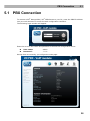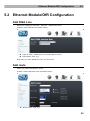
1
® 2N IVR Editor Voice Menu User Manual Version 1.0.2 www.2n.cz The 2N TELEKOMUNIKACE a.s. joint-stock company is a Czech manufacturer and supplier of telecommunications equipment. The product family developed by 2N TELEKOMUNIKACE a.s. includes GSM gateways, private branch exchanges (PBX), and door and lift communicators. 2N TELEKOMUNIKACE a.s. has been ranked among the Czech top companies for years and represented a symbol of stability and prosperity on the telecommunications market for almost two decades. At present, we export our products into over 120 countries worldwide and have exclusive distributors on all continents. 2N® is a registered trademark of 2N TELEKOMUNIKACE a.s.. Any product and/or other names mentioned herein are registered trademarks and/or trademarks or brands protected by law. 2N TELEKOMUNIKACE administers the FAQ database to help you quickly find information and to answer your questions about 2N products and services. On faq.2n.cz you can find information regarding products adjustment and instructions for optimum use and procedures „What to do if...“. Declaration of Conformity 2N TELEKOMUNIKACE a.s. hereby declares that the 2N® Omega Lite product complies with all basic requirements and other relevant provisions of the 1999/5/EC directive. For the full wording of the Declaration of Conformity see the CD-ROM enclosed and at www.2n.cz. The 2N TELEKOMUNIKACE company is a holder of the ISO 9001:2008 certificate. All development, production and distribution processes of the company are managed by this standard and guarantee a high quality and advanced technical level of and a professional approach to all of our products. Contents 1. Product Overview............................................................... 1 1.1 Product Description ....................................................................................................... 2 Basic Features.................................................................................................................. 2 ® Benefits of 2N IVR Editor Use ........................................................................................ 2 1.2 Innovations ..................................................................................................................... 3 1.3 Terms and Symbols Used ............................................................................................. 4 Symbols Used in Manual .................................................................................................. 4 Future Functions............................................................................................................... 4 2. Description and Installation .............................................. 5 2.1 Editor Description .......................................................................................................... 6 2.2 Installation ....................................................................................................................... 8 Porgram Installation ......................................................................................................... 8 2.3 Program Launch ........................................................................................................... 11 ® 2N IVR Editor Launch ................................................................................................... 11 3. 2N® IVR Editor Configuration .......................................... 12 3.1 Configuration ................................................................................................................ 13 New ....................................................................................................................... 13 Open ..................................................................................................................... 13 Save/Save as Export .............................................................................................. 13 ..................................................................................................................... 13 Answer ................................................................................................................. 14 Hang up ................................................................................................................ 14 Ring ..................................................................................................................... 15 Progress ............................................................................................................. 16 Wait ..................................................................................................................... 17 Play .......................................................................................................................... 17 DTMF Menu ......................................................................................................... 18 DISA Menu ........................................................................................................... 19 Calling Menu ........................................................................................................ 21 Called Menu ......................................................................................................... 22 Transfer ................................................................................................................ 25 4. Ethernet Module /OfR Configuration and IVR Recording27 4.1 PBX Connection ........................................................................................................... 28 4.2 Ethernet Module/OfR Configuration ........................................................................... 29 Add DISA Line ................................................................................................................ 29 Add route ........................................................................................................................ 29 LCR ................................................................................................................................ 30 4.3 Recording of IVR Configuration into Ethernet Module/OfR ..................................... 32 5. Supplementary Information ............................................ 35 5.1 Troubleshooting ........................................................................................................... 36 5.2 List of Abbreviations .................................................................................................... 37 5.3 General Instructions and Cautions ............................................................................ 38 1 1. Product Overview In this section, we introduce the 2N® IVR Editor product, outline its application options and highlight the advantages following from its use. Here is what you can find in this section: Product Description Innovations Terms and Symbols Used 1 Product Description 1.1 1.1 Product Description The 2N® IVR Editor application helps users create a user-defined voice menu for 2N® Omega PBX series and 2N® OfficeRoute systems. Call routing can be set according to the following criteria: DTMF dialling, called party number (CPN), or calling subscriber number (CLIP). Moreover, a user-defined voice message can be played, calls can be transferred and timeouts can be defined. Basic Features IVR – voice menu creation Up to 5MB configuration mp3, wav and alaw voice message playing While exported to tar.gz, the inserted mp3 and wav are reduced and converted into the alaw format. Benefits of 2N® IVR Editor Use Call routing in DTMF menu Entering the DTMF menu, you can route your call using the DTMF characters 0-9,* and #. Call routing according to CLIP If you know the calling subscriber number (a VIP client, e.g.), you can route the call via a route other than that for the other calls. Call routing according to CPN If your company has more numbers than one, you can route each called number to a different extension or department. Call routing in DISA Entering the DISA menu you can dial an internal subscriber/department number, or wait and descend to the next IVR level. Easy installation 2 Innovations 1.2 1.2 Innovations The manufacturer reserves the right to modify the product in order to improve its qualities. Manual version Revisions 1.0 The manual relates to IVR version 1.0.0.16 (Basic function). Caution In response to its customers’ requirements, the manufacturer constantly improves the IVR software. For the latest 2N® IVR Editor version and the User Manual refer to www.2n.cz. 3 Terms and Symbols Used 1.3 1.3 Terms and Symbols Used Symbols Used in Manual Caution Important information. Disobedience may result in a malfunction. Tip Useful information for easy and quick use and programming. Note Routines and advice for efficient use of the device. Future Functions The grey-marked text in this document designates the functions that are under preparation or development at present. 4 2 2. Description and Installation This section describes the 2N® IVR Editor product and its installation. Here is what you can find in this section: E Installation Program Launch 5 Editor Description 2.1 2.1 Editor Description The 2N® IVR Editor is a voice menu creating program. The following functions are available: - New -> Open a new IVR tree - Open -> Open an existing IVR tree - Save -> Save the IVR tree - Save as -> Save the IVR tree into another file - Export -> Create a tar.gz file for export to 2N® Omega - Answer -> Answer the call - Hang up -> Hang up the call - Ring -> Send RINGING to the calling user - Progress -> Send SEsubscriberION PROGREsubscriber plus tone?? to calling - Wait -> Wait for a defined count seconds before next operation - Play -> Play a user-defined voice message - DTMF menu - DISA menu - Calling menu - Called menu - Transfer - Centre -> Put the IVR tree in the screen centre 6 Editor Description 2.1 Caution These functions will be referred to in detail later. Before you start Installation Conditions 2N® IVR Editor is designed for Win XP, Win Vista and Win 7 operating systems. Install .Net Framework to make your 2N® IVR Editor work properly. Install your 2N® IVR Editor onto your PC hard disk; the editor size is very small (a few MB). 7 Installation 2.2 2.2 Installation Program Installation Install IVR from the IVRsetup.msi file. Together with IVRsetup.msi, the folder has to contain setup.exe. Either file is necessary for installation. The IVR wizard is launched. Now continue by clicking Next. Here select the path to the installation folder. C:\Program Files\2N TELEKOMUNIKACE\2N IVR Editor is selected by default. Click on Browse to select another path (another installation folder on the hard disk). Push Disc cost to display vacancies on your PC hard disks. 8 Installation 2.2 3. Select Just me to restrict the editor to yourself, or Everyone to make the IVR Editor accessible to multiple PC users. Having completed the settings, click Next to continue 9 Installation 2.2 Caution Check .NET Framework using Windows update please. 10 Program Launch 3.1 3.1 Program Launch 2N® IVR Editor Launch Launch the 2N® IVR Editor using the Start – Programs – 2N TELEKOMUNIKACE – 2N IVR Editor menu or the appropriate short-cut icon on the desktop. Or, launch the IVR Editor from C:\Program files\2N TELEKOMUNIKACE\2N IVR Editor\IVR.exe (unless you have selected another installation folder for your IVR Editor). 11 3 ® 4. 2N IVR Editor Configuration This section describes the 2N® IVR Editor configuration. The meanings of some functions including examples will be given for easier configuration. 12 Configuration 4.1 4.1 Configuration The voice message configuration runs in the 2N® IVR Editor program. The grey text denotes a menu that is displayed by the right mouse click. New Create a new configuration. Open Open the configuration from a file. Save/Save as Save – Save a non-saved configuration into a file. Save as – Save the configuration into a file other than the original one. Export Create a tar.gz file. Export the file to the 2N® OfficeRoute/2N® Omega PBX Ethernet module. Caution You cannot re-open the file in the IVR Editor program. Use Save or Save as to save the file. 13 Configuration 4.1 Answer Answer the call. Insert this function at the beginning of the IVR tree to make a call be answered. Change destination Create a path to a new, existing or no destination. Modify Delay – set the call answering timeout. Remove Remove the Answer function. Caution – IVR without Answer You can use the IVR tree without the Answer function too but with the Called and Calling menus only, where the call is routed according to the called/calling number. The voice message related to the Called/Calling menu is not played. The voice message is played in the menu but not in the call, which results in a call transfer delay (the call is not transferred until the menu voice message has been played). Do not set any voice message to eliminate the call transfer delay. Hang Up Use the Hang up function at the end of the IVR tree to terminate the call instead of go on routing. No destination follows this function. Rename Rename the destination for better orientation in the IVR tree. Remove Remove the Hang up function. 14 Configuration 4.1 Ring Insert this function, together with Wait, before the Answer function at the beginning of the IVR tree. The calling subscriber can hear the ringing tone and waits for a defined period of time before being answered. The purpose of this function is to make the calling user hear the ringing tone before entering IVR without being confused by immediate answering and voice message playing. Rename Rename the destination for better orientation in the IVR tree.ee Change destination Create a path to a new, existing or no destination. Remove Remove the Ring function. Example: A user calling to IVR can hear 10s ringing, is answered and played the DISA message in the DTMF menu where further dial-in can be made. 15 Configuration 4.1 Progress Insert this function, together with Play, before the Answer function at the beginning of the IVR tree. The calling subscriber can hear the voice message defined in the Play function instead of ringing. Rename Rename the destination for better orientation in the IVR tree. Change destination Create a path to a new, existing or no destination. Remove Remove the Progress function. Example: A user calling to IVR is played the welcome note. After the welcome note, the call is answered and proceeds to the DTMF menu. 16 Configuration 4.1 Wait Wait for a defined period of time before proceeding to the next destination in the IVR tree. Rename Rename the destination for better orientation in the IVR tree. Change destination Create a path to a new, existing or no destination. Modify ID – see Rename. Delay – set the waiting time before proceeding to the next destination. Remove Remove the Wait function. Play Play the user-defined voice message. Having created this function, you are immediately invited to insert a voice message. You cannot add the function without inserting a voice message. In addition, you can set Discontinue on DTMF and a delay. Change destination Create a path to a new, existing or no destination. Modify Play message – modify the set voice message. Discontinue on DTMF – discontinue the voice message whenever a DTMF character is pressed. Delay – set the voice message playing timeout. Caution Supported audio formats: wav, mp3 and alaw. wma formats are not supported now. 17 Configuration 4.1 DTMF Menu If you create a DTMF menu, the call is routed using the defined DTMF characters (09,* and #), or with the symbol in other cases (when the DTMF character is not entered within a timeout, or a non-defined DTMF character is entered). Rename Rename the destination for better orientation in the IVR tree. Modify ID – see Rename. Delay – set the delay before voice message playing and DTMF dialling. Play message – select or change the voice message to be played. Discontinue on DTMF – discontinue the voice message whenever a DTMF character is pressed. DTMF timeout – set the DTMF receiving timeout after which the call is routed via . Add DTMF Add a DTMF character (0-9,* and #) to be used for next destination routing. You can use the function to add a DTMF character too. Remove Remove the DTMF menu. DTMF Menu Control - add a DTMF char – no more adding will be possible if all characters are exhausted. - go on in other cases – select a path to the destination with this symbol if a defined DTMF character is not received, or the DTMF receiving timeout has elapsed. 18 Configuration 4.1 - set delay – click on the right-hand mouse button and then on Modify to get into the delay changing menu. - set the message to be played. Left mouse click to set the message. If already set, the message is played. Re-click to discontinue the message unless it has stopped. Right mouse click and select Modify or Play. Play – play the message. Modify – modify the message and Discontinue on DTMF. DISA Menu This menu is particularly useful if the calling subscriber knows the internal subscriber dial-in number. If the calling subscriber does not know the internal subscriber number, the other route is selected (No DTMF), to the secretary, for example. Caution Enter Transfer DTMF behind the symbol to execute call transfer to a known number from the DISA menu successfully. 19 Configuration 4.1 Example of configuration: Suppose you get through to IVR, enter the DISA menu m0 with a 1s delay. You will be played the IVR message (‘If you know the subscriber number, enter the number’, ‘If you do not know the subscriber number, wait’). If you know the subscriber number, dial it (using Transfer DTMF). If you enter nothing, the call will be routed via No DTMF to DTMF menu m1 after a DTMF receiving timeout. If you do not select any of the available DTMF menu items (Dial 1 for Czech trade; Dial 2 for foreign trade; Dial 3 for marketing, etc.), the call will be hung up. Rename Rename the destination for better orientation in the IVR tree. 20 Configuration 4.1 Modify ID – like Rename Delay – set the delay before voice message playing and DTMF dialling. Play message – select or change the voice message to be played. Discontinue on DTMF – discontinue the voice message whenever a DTMF character is pressed (this function is always enabled in this menu and cannot be changed). DTMF timeout – set the DTMF receiving timeout after which the call is routed via . Max count of DTMF chars – set the maximum number length. If a line number is longer than the value set in this parameter, the line will not be accessible. If a line number is shorter than the maximum value, the menu will wait for more characters for a while (DTMF timeout) and then the call will be set up. End character – select a character to terminate dialling with a DTMF character instead of defining the Max count of DTMF chars. DTMF characters * and # are the best choice since they are not included in internal subscriber numbers. Caution – Max count of DTMF chars The ringing table will be used for calls to the PBX when the internal line is not identified. The ringing able will also be used for routing calls to a defective key system phone. The call will be hung up for calls to a VoIP phone when the telephone number is not identified. Example: If you use two-digit numbering for your PBX and four-digit numbering for your SIP phones, set the Max count of DTMF chars parameter to 4. Whenever 4 digits are dialled, the call is immediately routed to the matching line. When 2 digits are dialled, the menu waits for a defined count of seconds (DTMF receiving timeout) to connect the call. Calling Menu Calls are routed according to the Caling Line Identification Presentation (CLIP) from this menu. Tip This function is particularly useful for VIP clients, which can be routed directly, without additional dial-ins. For other, non-matching numbers, the route will be used. 21 Configuration 4.1 Example: Suppose you get through to IVR. If your number is 602123456 or 603987654, you will be immediately routed to department 1 (line 10, VIP client salesman, e.g.). If your number is different, you will be routed to department 2 (line 20, more salesmen for more clients) and played the DISA message. Then you will wait for 5s as defined and be transferred to line 20 (dept. 2). Called Menu Calls are routed according to the Called Party Number (CPU) from this menu. The CPN comes in the full format: 222333411, for example. Use normalisation to avoid long number entering into the IVR Editor (222333411). Remove the prefix (2223334) and add 6 to get number 611 (6 – added number, 11 – remaining number from 222333411) for IVR. 6 is LCR routing to IVR and 11 is the internal subscriber number. Caution - normalising Enter 2223334 and add 6 for IVR routing. 11 is the internal subscriber number. 22 Configuration Enter 611 in the Called menu to make call routing successful. 6 is not removed in the LCR and so all numbers must have 6 at their beginnings in IVR. 6 is the default value for IVR routing in the LCR (can be changed). 4.1 Figure: Call Routing with Normalisation Caution Be sure to set the LCR correctly if you use the Called menu. Be sure to remove the prefix correctly if you use normalising. Remember to add 6 for routing via LCR to IVR when you have removed the prefix. Normalising Settings for Called 23 Configuration 4.1 For normalising, remove the prefix 2223334 and add 6. As a result, 611 will be routed to IVR. Change the type to Called incoming in the normalising window. For another called number, 555666711, e.g., remove the prefix 5556667 and add 6 again for routing to IVR. The result is number 611. LCR Settings for Called In our example, number 611 will always enter the LCR after normalisation (generally, the number is 6XX, where XX represents the last two digits of the CPN). 1 and 2 – route to PBX (PBX numbers 11-29); 3 – route to VoIP (VoIP phones such as 3001); 5;vm- - route to VoiceMail; 6 – route to IVR. The LCR is based on a prefix. If a prefix is detected, the call is routed via the given route. Example: Suppose 611 is incoming. As there is a ‘6’ at the beginning, the call is routed to IVR. 6 is not removed so that the number remains 611 at all times. 24 Configuration 4.1 Caution The prefix must always start with a different digit. Thus, there may be just one prefix for IVR routing. All called numbers are normalised. For normalising, remove the prefix leaving a three-digit number (both after normalisation and addition). In this case, number 6XX is always the result of normalising (where XX represents the last two digits of the called number, generally the internal line number). Transfer There are two types of call transfer. Transfer DTMF This call transfer type is used for the DISA menu only where the calling subscriber knows the called subscriber number and dials in. Transfer DTMF: Transfer to Number For this call transfer type, enter the number of an internal line, department (user groups in 2N® OfficeRoute), VoIP phone connected to the 2N® Omega PBX Ethernet module/2N® OfficeRoute, or an external telephone. Example: - transfer to department 10 (LCR routes the call via the PBX). 25 Configuration 4.1 - transfer to internal line 11 (LCR routes the call via the PBX). - transfer to VoIP line 3001 (LCR routes the call via VoIP). - transfer to a mobile phone (the number is for example only, generally, LCR and call routing settings are required for this function). Caution The LCR has to be set properly for external call routing (outside the PBX). 26 4 5. Ethernet Module /OfR Configuration and IVR Export This section describes the 2N® Omega PBX Ethernet module/2N® OfficeRoute configuration. Here is what you can find in this section: Configuration Ethernet Module Configuration Export of IVR Configuration to Ethernet module/OfR Configuration of 2N® Omega PBX Basic Part 27 PBX Connection 5.1 5.1 PBX Connection To connect a 2N® Omega PBX / 2N® OfficeRoute to your PC, enter the PBX IP address into your web browser to access the web configuration interface. The following login window will appear. Enter the correct user name and password to access the configuration menu. User name: admin Password: ***** Having done so correctly, you will get the main page. 28 Ethernet Module/OfR Configuration 5.2 5.2 Ethernet Module/OfR Configuration Add DISA Line Open the Telephony services – Devices – DISA lines menu. Create a new DISA line as shown below. Type of DISA : DISA/IVR on internal Flash memory. Description: IVR, e.g. Now that you have added the line, set the route. Add route Enter the Least Cost Router (LCR). Create a new DISA-IVR route as shown below. Route name: IVR, e.g. 29 Ethernet Module/OfR Configuration Lines of route: DISA – IVR. Time interval: define on which days the IVR route should be effective (weekdays, weekend, workdays). Select all the options (Ctrl + click on interval) for always. CLIP/CLIR: set default (for both CLIP and CLIR). Description: need not be completed. 5.2 Now that you have added the route to IVR, proceed to the LCR. LCR Here set the prefix for routing calls to IVR. Click on Add in the LCR window. The LCR settings will get displayed. 30 Ethernet Module/OfR Configuration Enabled: be sure to tick off the checkbox. Destination name: IVR, e.g. Prefix: 6 is the default value (can be changed). Line selection: default. 5.2 Now IVR is set successfully. The following subsection describes how to upload the IVR file to the 2N® Omega PBX Ethernet module /2N® OfficeRoute. 31 Upload of IVR Configuration to Ethernet Module/OfR 5.3 5.3 Upload of IVR Configuration to Ethernet Module/OfR Enter the PBX IP address into your web browser and enter the Admin password. Enter the Telephony services – Devices – DISA lines menu. Click on the DISA/IVR symbol (blue symbol in the right-hand bottom corner) to get to the IVR configuration adding menu (tar.gz). 32 Upload of IVR Configuration to Ethernet Module/OfR 5.3 Click on Browse to select the path to the tar.gz file in your PC and push Add to save the file into your internal Flash memory. To update a new IVR configuration, click on Update (‘pencil’) next to the selected DISA line. Having updated, click on the Modify (‘diskette’) to save the changes (even if no changes have been made). 33 Upload of IVR Configuration to Ethernet Module/OfR 5.3 Caution Be sure to update any new IVR configuration using the Update (‘pencil’) symbol next to the selected DISA – IVR line. Do not change anything in the DISA – IVR line setting, just confirm the changes. Click on the ‘diskette’ symbol in the right-hand bottom corner to save the file. Now your IVR configuration is updated and available. 34 5 6. Supplementary Information This section provides supplementary information on the 2N® IVR Editor product. Here is what you can find in this section: Troubleshooting List of Abbreviations General Instructions and Cautions 35 Troubleshooting 6.1 6.1 Troubleshooting For tips concerning solutions of other potential problems see faq.2n.cz. I cannot see the configuration in the 2N® IVR Editor. Voice messages cannot be played in the 2N® IVR Editor. Place the configuration into the centre of the screen. Check the voice message format (mp3, wav). I cannot get through to IVR. Check the LCR settings by, for example, calling via the trunk with VoIP from the PBX and accessing IVR. Set 866 for the internal line by default. (only for Omega Lite/48) The changes have no effect on IVR. Update IVR by clicking on the ‘pencil’ and resave the configuration in the Telephony services – Devices – DISA lines – web interface menu. 36 List of Abbreviations 6.2 6.2 List of Abbreviations CLIP - Calling Line Identification Presentation DTMF - Dual Tone MultiFrequency IVR - 2N® IVR Editor program FW - firmware LCR - Least Cost Router (set in the PBX VoIP module) OfR - 2N® OfficeRoute PBX, PABX – Private (Automatic) Branch Exchange PC - Personal Computer, IBM PC compatible SW – software IL – internal line 37 General Instructions and Cautions 6.3 6.3 General Instructions and Cautions Please read this User Manual carefully before using the product. Follow all instructions and recommendations included herein. Any use of the product that is in contradiction with the instructions provided herein may result in malfunction, damage or destruction of the product. The manufacturer shall not be liable and responsible for any damage incurred as a result of a use of the product other than that included herein, namely undue application and disobedience of the recommendations and warnings in contradiction herewith. Any use or connection of the product other than those included herein shall be considered undue and the manufacturer shall not be liable for any consequences arisen as a result of such misconduct. Moreover, the manufacturer shall not be liable for any damage or destruction of the product incurred as a result of misplacement, incompetent installation and/or undue operation and use of the product in contradiction herewith. The manufacturer shall not be liable and responsible for any loss or damage incurred as a result of a natural disaster or any other unfavourable natural condition. The manufacturer shall not be held liable for any damage of the product arising during the shipping thereof. The manufacturer shall not make any warrant with regard to data loss or damage. The manufacturer shall not be liable and responsible for any direct or indirect damage incurred as a result of a use of the product in contradiction herewith or a failure of the product due to a use in contradiction herewith. The consumer shall, at its own expense, obtain software protection of the product. The manufacturer shall not be held liable and responsible for any damage incurred as a result of the use of deficient or substandard security software. The consumer shall, without delay, change the access password for the product after installation. The manufacturer shall not be held liable or responsible for any damage incurred by the consumer in connection with the use of the original password. The manufacturer also assumes no responsibility for additional costs incurred by the consumer as a result of making calls using a line with an increased tariff. 38 2N TELEKOMUNIKACE a.s. Modřanská 621, 143 01 Prague 4, Czech Republic Tel.: +420 261 301 500, Fax: +420 261 301 599 E-mail: [email protected] Web: www.2n.cz 1641v1.0.2