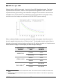
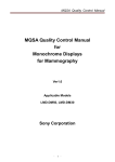
1
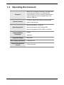
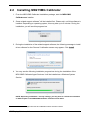
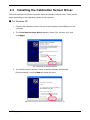
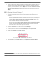
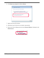
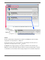
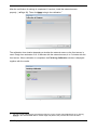
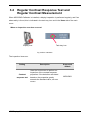
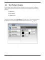
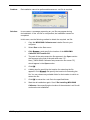
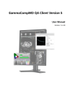
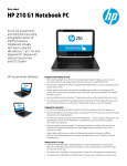
MD215MG Calibrator
User's Manual
Version 1.0
Contents
1 Introduction..........................................................................................................3
1.1 Overview.....................................................................................................................3
1.2 Operating Environment.............................................................................................4
2 Installation............................................................................................................5
2.1 Installing the Display.................................................................................................5
2.2 Installing MD215MG Calibrator.................................................................................6
2.3 Installing the Calibration Sensor Driver..................................................................9
3 Main Functions...................................................................................................12
3.1 Main Menu and Task Tray Icon...............................................................................12
3.2 Calibration................................................................................................................14
3.3 Display Inspection...................................................................................................19
3.4 Regular Contrast Response Test and Regular Contrast Measurement.............21
4 Useful Functions................................................................................................22
4.1 Calibration History...................................................................................................22
4.2 Test Pattern Display.................................................................................................24
4.3 Options......................................................................................................................25
5 De-installing MD215MG Calibrator...................................................................25
6 Troubleshooting.................................................................................................26
6.1 Display Status..........................................................................................................26
6.2 Other Problems........................................................................................................27
7 After-sales service.............................................................................................29
8 Appendix.............................................................................................................30
8.1 Attaching the Calibration Sensor...........................................................................30
8.2 Gamma Correction...................................................................................................31
8.3 Custom Gamma Correction File.............................................................................32
8.4 Test Patterns............................................................................................................33
8.5 How to Read the Graphs.........................................................................................36
NEC Display Solutions, Ltd.
-2-
1
Introduction
This document describes how to use the NEC MD215MG Calibrator. Please read
this user's manual before use to ensure proper functioning.
1.1
Overview
MD215MG Calibrator is software designed to manage the quality of NEC medical image
displays. The functions include:
■ Monitoring of display status: The display configuration is recognized automatically and is
shown resident as an icon in the task tray, notifying the user of the display status. After
starting the application, use this function to quickly check the display status.
Page 12
■ Display Adjustment: Perform various adjustments, including calibration to DICOM GSDF
or other gamma correction curves.
Page 14
■ Display Inspection: Test of luminance and gamma correction curve.
Page 19
■ Calibration History: Easily check details of previously performed calibrations and display
inspections.
Page 22
■ Test Pattern Display: Display test patterns using either AAPM TG18 test patterns
or other QA testing standard test patterns.
NEC Display Solutions, Ltd.
Page 24
-3-
1.2
Operating Environment
Computer
System memory
IBM PC/AT compatible computers, equipped with
processors equivalent to or exceeding Intel
Pentium/Celeron 2 GHz, meeting recommended
system requirements and equipped with more
than one USB port
512 MB or higher and meeting recommended
system requirements
Microsoft Windows 7 32/64-bit
Operating system
Microsoft Windows Vista 32/64-bit SP2
Microsoft Windows XP 32-bit SP3 / 64-bit SP2
Supported Menu
Languages
Supported display
Max. display attachment
Supported calibration
sensors
NEC Display Solutions, Ltd.
English
Japanese
MD215MG
6 displays total
X-Rite Chroma 5
-4-
2
Installation
This chapter explains how to connect cables and install the hardware and software. Make sure
to log in as a user with administrative privileges on a local computer before starting installation
of MD215MG Calibrator.
2.1
Installing the Display
Connect the DVI video cable and the USB cable, as supplied with the display, between the
ports on the display and the computer. For detailed information on cable connections,
including multiple display setup, please refer to the MD215MG Installation & Maintenance
Guide.
DVI Video cable
USB cable
Chroma 5
To AC outlet
Fig. 1:Computer to display connections
NEC Display Solutions, Ltd.
Computer
-5-
2.2
Installing MD215MG Calibrator
1. From the MD215MG Calibrator Installation package, start the MD215MG
Calibrator.exe installer.
2. Some related support software1 will be installed first. Please wait, until this software is
installed. Depending on operating system, this may take up to 2 minutes. During the
installation, you will see this progress bar.
Fig. 2:Progress bar
3. During the installation of the related support software, the following message to install
driver software for the Chroma 5 calibration sensor may appear. Click install.
install
Fig. 3:Windows security message
4. You may see the following installation progress bar during the installation of the
MD215MD Calibrator Agent Services. It will be installed as a Windows System
Service.
Fig. 4:MD215MG Calibrator Agent Services message
NOTE: Depending on Window 7 security settings, you may have to confirm the installation
of different parts of the MD215MG Calibrator software several times.
1
MD215MG Calibrator Agent Services and calibration sensor Chroma 5 driver
NEC Display Solutions, Ltd.
-6-
5. When the installation of the related support software is completed, the MD215MG
Calibrator setup wizard starts. Click Next > to begin the installation of the MD215MG
Calibrator software.
Fig. 5:License Agreement confirmation
6. The License Agreement window appears. To accept the agreement and proceed
with installation, select "I Agree" and click Next >.
>
7. When the Select Installation Folder window appears, select a destination folder.
Further down the menu, you can select, in which user's Start menu the shortcut to
this software should be created. To share it with all users of this computer, select
"Everyone". To use it only by yourself, select "Just me". Then click Next >.
>
Fig. 6:Select Installation Folder
NEC Display Solutions, Ltd.
-7-
8. When the Confirm Installation window appears, click Next > to start installation.
Fig. 7:Confirm Installation
9. When the Installation Complete window appears, click Close to complete
installation.
10. A message appears, prompting for restart of the computer. Click Yes and
restart the computer.
Fig. 8:Confirm Restart of system
After the computer restarts, MD215MG Calibrator Agent Services starts as a Windows System
Service and the display configuration is detected automatically. All displays - not only
supported displays - are detected.
The MD215MG Calibrator software is now ready for use.
NEC Display Solutions, Ltd.
-8-
2.3
Installing the Calibration Sensor Driver
Follow the instructions below to install the external calibration sensor driver. There are two
ways, depending on the Operating System of the computer.
● For Windows XP
1. Connect the calibration sensor Chroma 5 to the display or the USB port on the
computer.
2. The Found New Hardware Wizard appears. Select "Yes, this time only," and
click Next >.
>
Fig. 9:Found New Hardware Wizard
3. The following screen appears. Select "Install the software automatically
[Recommended]," and click Next > to install the driver.
Fig. 10:Confirm installation of the Chroma 5 external sensor
NEC Display Solutions, Ltd.
-9-
4. When the MD215MG Calibrator installation has been properly completed, the driver
software was found and installed automatically. If the driver installation has failed,
please try manual installation. Click the Back button and select Install from a list or
specific location [Advanced]. Specify the device driver location/source then click
Next >.
>
● For Windows Vista and Windows 7
1. Connect the calibration sensor Chroma 5 to the display or the USB port on the
computer.
■ When the MD215MG Calibrator installation has been properly completed, the
message Device driver software was successfully installed appears. The
driver installation has been completed successfully.
■ When the message Device driver software was not successfully installed
appears, first install the MD215MG Calibrator software and then connect the
Chroma 5 sensor. If this still fails, go to the next step.
2. Right-click Computer2 on the Start menu and select Manage.
3. In the left pane of the window, select Device Manager under System Tools.
4. Double-click Calibrator under Other devices.
Fig. 11:System Tools - Device Manager - Other Devices
5. On the Driver tab, click Update driver to open Update Driver Software Wizard.
2
The description "Computer" can be "My computer" depending on the Operating System you are using.
NEC Display Solutions, Ltd.
- 10 -
6. Click Browse my computer for driver software.
Fig. 12:Update Driver Software - Calibrator
7. Specify the device driver location.
8. Windows will now find the driver and installs it automatically.
9. Return to the Device Manager and check that Chroma Calibrator is displayed under
X-Rite Devices.
Fig. 13:Chroma Calibrator installed
NEC Display Solutions, Ltd.
- 11 -
Main Functions
3
MD215MG Calibrator comes with the necessary functions for managing the accuracy of the
display for displaying medical images.
3.1
Main Menu and Task Tray Icon
When MD215MG Calibrator starts with Windows, an icon resides in the task tray. This icon is
an indication of display monitoring, to notify the user of the display status.
You may decide later, whether or not the MD215MG Calibrator icon resides in the task tray.
Page 25.
MD215MG Calibrator task tray icon
Fig. 14:Task tray icon
The task tray icon indicates display status information as below:
Icon
Status
Normal: Normal Operation.
Warning: Display status cannot be verified.
Error: Display error detected.
Detailed status information of warnings and errors are displayed in the MD215MG Calibrator
main menu. To open the main menu, either select MD215MG Calibrator on the Windows Start
menu, or right-click the task tray icon and select Open MD215MG Calibrator.
NEC Display Solutions, Ltd.
- 12 -
Fig. 15:Elements of the MD215MG Calibrator main menu
・ Home tab
・ Test Patterns tab
(
Page 24)
・ Options tab
(
Page 25)
NOTES:
■ When multiple display configurations are enabled in the Option tab, select the display
configuration in the drop-down box.
Page 25
■ Placing the mouse cursor over the display icon on the displays in the main menu, an
explanation of the display status is shown.
Page 26
■ Important: Any change of settings on the display via OSD will not be reflected in the
Home tab, unless the MD215MG Calibrator software is closed and restarted again. Therefore
it is advisable to use the software method to apply changes of the 3 selectable configurations.
NEC Display Solutions, Ltd.
- 13 -
3.2
Calibration
Perform calibration by using the Calibration button on the Home tab. Clicking Calibration for
the display to be adjusted displays the Starting Calibration window. Calibration can be
performed with either the the front sensor or the Chroma 5 external sensor. When an external
sensor is connected, clicking Calibration enables the external sensor to be used. When an
external sensor is not connected, the front sensor is used3.
■ Important: For more accurate calibration, use the external sensor to perform a
calibration. When a calibration is performed using the external sensor, a calibration of the
front sensor is performed as well. It is recommended to do an external sensor calibration
regularly, about once a year.
Fig. 16:Starting Calibration menu
Check the following information on the Starting Calibration menu.
■ Calibration Settings: Displays the calibration settings. Displays the previous calibration
results by default. To change the settings, click Change Settings.
Settings
■ Sensor: Displays the sensor used for calibration. If zero calibration of the external sensor is
required, the Zero Calibration button is displayed. Place the sensor on an even surface and
click the button. Not required in conjunction with Chroma 5 external sensor.
■ Elapsed time since the display is turned on: Displays the elapsed time since the display
was turned on4. If the elapsed time is too short, calibration cannot be performed accurately.
Wait at least 60 minutes after the display is turned on before beginning calibration.
3
4
If the sensor manual selection option is enabled (
Page 25) and you select External Sensor, the
external sensor is selected.
This is the elapsed time since the display was turned on. If the power save function is enabled or power
is turned off, the value returns to 0. Please disable the Windows power save function for this purpose.
NEC Display Solutions, Ltd.
- 14 -
Calibration Settings
The following items can be changed on the Calibration Settings dialog that appears when
clicking Change Settings.
Settings
Fig. 17:Calibration Settings menu
When multiple configurations are enabled in the Option tag, the following items are also
displayed.
Page 25
Setting
Description
Display
Configuration
Select the display configuration to be
adjusted.
Configuration
Name
Specify the name of the configuration.
This field is optional.
NEC Display Solutions, Ltd.
- 15 -
Additional information
Can only be set when
multiple configurations are
enabled with the
MD215MG Calibrator
settings.
Page 25
Setting
Max. Luminance
Description
Specify the luminance (cd/m2) when
white is displayed. Use the default
value unless otherwise required.
Maximum luminance can be set within
the range specified for the display.
Min. Luminance
Ambient Light
Gamma
Comment
5
6
Specify the luminance (cd/m2) when
black is displayed. Use the default
value unless otherwise required.
Specify the luminance (cd/m2) affecting
the display surface according to the
ambient light.5
If the effect of ambient light does not
need to be taken into account, use the
default value of 0.0 cd/m2 .
Additional information
Due to luminance
degradation caused by
deterioration of the
backlight over time, the
result may fall short of the
target luminance.
May be lifted up to comply
with regulations or recommendations, i.e. PAS
1054 = min. 1.0 cd/m2 or
NHS guidelines for
Mammography systems.
A Measure button is
displayed,6 as an ambient
light sensor is integrated
into the MD215MG.
Specify the gamma properties.
Page 31
If grayscale images will be displayed,
DICOM GSDF is recommended.
Add a comment at the time of
adjustment for later reference. This
information is optional.
When ambient light is set, the ambient light value will be added to the resulting maximum and minimum
luminance.
Measurements using the integrated ambient light sensor uses a proprietary method. To manage
displays according to QA testing standards, refer to respective relevant standards.
NEC Display Solutions, Ltd.
- 16 -
After the verification of settings is completed, if required, install the external sensor
properly (
Page 30). Then click Start to begin the calibration.7
Fig. 18:Calibration in Progress
The calibration time duration depends on whether the external sensor or the front sensor is
used. Rough time estimates: 9 to 10 Minutes with the external sensor, 4 to 5 minutes with the
front sensor. When calibration is completed, the Finishing Calibration window is displayed
together with the results.
Fig. 19:Calibration Finished
7
You can cancel adjustment by pressing the ESC key on the screen during adjustment or by clicking
Cancel in the wizard. Note: After a certain stage has passed, the process cannot be canceled.
NEC Display Solutions, Ltd.
- 17 -
Result
Description
Calibration completed normally, also passed inspection.
Pass
Fail
Calibration completed normally, but during inspection, a deviation
was outside the appropriate range (
Page 37). Allow for more
elapsed time since the display was turned on, and then perform
the calibration again.
If the result is still Fail, the display may have a problem.
Click on Show Details to display the details of the calibration results in different graphs.
For how to read the graphs, see
NEC Display Solutions, Ltd.
Page 36.
- 18 -
3.3
Display Inspection
Clicking Display Inspection on the Home tab starts the display inspection. Display inspection
can be performed with either the the front sensor or the Chroma 5 external sensor. When an
external sensor is connected, clicking Display Inspection enables the external sensor to be
used. When an external sensor is not connected, the front sensor is used.8
■ Important: For more accurate display Inspection, use the external sensor.
If the front sensor is selected and at least 60 minutes have elapsed since the display was
turned on, inspection begins immediately. Otherwise, the Starting Display Inspection
window appears. Check the following information on this menu.
Fig. 20:Starting Display Inspection
■ Sensor: Displays the sensor, which is used for inspection. If a zero calibration with the
sensor is required, the Zero Calibration button is displayed. Place the sensor on an even
surface and click the button. Not required in conjunction with the Chroma 5 external sensor.
■ Elapsed time since the display is turned on: Displays the elapsed time since the display
was turned on9. If the elapsed time is too short, inspection cannot be performed accurately.
Wait at least 60 minutes after the display is turned on before beginning inspection.
8
9
If the sensor manual selection option is enabled (
Page 25) and you select External Sensor, the
external sensor is selected.
This is the elapsed time since the display was turned on. If the power save function is enabled or power
is turned off, the value returns to 0. Please disable the Windows power save function for this purpose.
NEC Display Solutions, Ltd.
- 19 -
After the verification of settings is completed, if required, install the external sensor
properly (
Page 30). Then click Start to begin the display inspection.10
When inspection is completed, the Finishing Display Inspection window is displayed
together with the results.
Fig. 21:Display Inspection finished
Result
Description
The inspection result passed.
Pass
Fail
The inspection result failed. Please perform a re-calibration
of the display.
Click on Show Details to display the details of the inspection results in in different graphs.
For how to read the graphs, see
Page 36.
10 You can cancel inspection by pressing the ESC key on the screen during inspection or by clicking
Cancel in the wizard. Note: After a certain stage has passed, the process cannot be canceled.
NEC Display Solutions, Ltd.
- 20 -
3.4
Regular Contrast Response Test and
Regular Contrast Measurement
When MD215MG Calibrator is installed, a display inspection is performed regularly, and if an
abnormality is found, this is indicated in the task tray icon and in the Home tab of the main
menu.
When an inspection error has occurred
Display icon
Task tray icon
Task tray icon
Display icon
Fig. 22:Error indication
The inspection items are:
Setting
Contrast
response test
NEC Display Solutions, Ltd.
Description
Uses the front sensor to perform an
inspection of the contrast response
properties. If the deviation calculated
based on the properties greatly
exceeds the standard value, an error
occurs.
- 21 -
Supported
models
MD215MG
Useful Functions
4
MD215MG Calibrator comes with useful functions for managing the accuracy of the display for
medical images reproduction. You can perform a detailed analysis of the display quality and
manage complex display configurations.
4.1
Calibration History
You can display the results of previously performed calibrations and display inspections both
graphically and numerically.
● Displaying the detailed calibration information
1. Click History on the Home tab of the main menu.11
2. Select a display in the Calibration History section. The calibration history for the
selected display appears below.
3. Select a record from the calibration history to display the detailed settings information
in the Calibration Settings section.
3
2
Fig. 23:Calibration History
11 If a calibration has not yet been done, the History button is disabled.
NEC Display Solutions, Ltd.
- 22 -
● Displaying the calibration results graphically
1. Select a calibration record and click Add to add it to the Selected Items section.
2. To compare with other records, select multiple records using the same procedure.
You can compare two records graphically at the same time.
3. Click Create.
Create (For how to read the graphs
Page 36)
1
2
3
Fig. 24:24 Record selection
NEC Display Solutions, Ltd.
- 23 -
4.2
Test Pattern Display
You can select between different methods to display full-screen test patterns, one Basic
method and three advanced methods, as proposed by the three different major QA testing
standards.
■ AAPM TG18
■ DIN V 6868-57
■ JESRA X-0093
To display a test pattern, select Test Patterns on the main menu. The selected test patterns
are displayed on the selected display. For all available test patterns see
Fig. 25:Test Patterns selection
NEC Display Solutions, Ltd.
- 24 -
Page 33.
4.3
Options
MD215MG Calibrator includes the following options to changing the software operation.
To change the settings, open the Options tab on the main menu.
After you configure the settings, click Apply to apply the settings to MD215MG Calibrator.
Setting
5
Description
Hide icon in Windows
task tray
When this is selected, the icon does not reside in
the task tray. Closing the main menu exits the
application.
Enable multiple
display configuration
Displays and enables switching of display
configurations using the Home tab on the main
menu and calibration settings.
Enable manual sensor
selection
Enables manual selection of the front sensor and
external sensor when performing calibration and
inspection.
De-installing MD215MG Calibrator
To de-install MD215MG Calibrator, select Uninstall a program from Windows Control Panel.
Then select NEC MD215MG Calibrator. All related software12 will be de-installed as well.
■ If a message requesting an .msi file appears during de-installation, please refer to
Troubleshooting
Page 28.
■ After de-installation, the installation folder may remain on the system.
Delete this folder manually, as needed.
12 MD215MG Calibrator Agent Services is de-installed at the same time.
NEC Display Solutions, Ltd.
- 25 -
Troubleshooting
6
6.1
Display Status
The display status is indicated by the task tray icon and on the main menu. Placing the
mouse cursor over the display icon on the main menu of the Home tab displays a detailed
explanation of the display status.
Icon
Message
Solution
Status OK
Check the connection between the
computer and display.
Page 5
When a communication error occurs for
or
Communication Error
a display detected for the first time,
appears. When a communication error
occurs for a display previously detected,
appears.
The registered information of the display
configuration and actual connection do
not match. Check the connection
between the computer and display(
Page 5) and the on-screen settings.
No Video Cables
Contrast Response Test Failed
Calibration Recommended
The display does not support calibration
or other adjustments. It can be used as
is.
Unsupported Display
NEC Display Solutions, Ltd.
Page 14
If this error occurs, use of an external
sensor is recommended.
Luminance Change Larger
Calibration Recommended
No Icon
Perform a calibration.
- 26 -
6.2
Other Problems
Problem:
The message "Application cannot be started." appears and the application
cannot be started.
Solution:
A communication error may occur when an application other than MD215MG
Calibrator is communicating with the display. Before starting MD215MG
Calibrator, be sure to close all other applications. Also, a display inspection
may be running in the background, so wait a moment before starting the
application.
Problem:
The calibration sensor Chroma 5 is not recognized even when connected, or
an error message, such as "Sensor not found," appears.
Solution:
Depending on the computer, Chroma 5 may not be recognized when the
computer is turned on even if Chroma 5 is connected.
How to find out whether or not the calibration sensor is recognized:
1. Right-click Computer on the Start menu and select Manage.
2. In the left pane of the window, select Device Manager under System
Tools.
3. In the right pane of the window, check the Device Manager. If
Chroma Calibrator is listed under X-Rite Devices, the calibration
sensor is recognized; if it is not recognized, it appears as either Other
Devices or USB Device.
How to get the Chroma 5 recognized:
①. If Chroma 5 is not recognized, even if the driver is installed, reconnect
Chroma 5 after the operating system has started.
If the driver is not installed, install it at this time.
Page 9
②. Before starting QA testing with NEC GammaCompMD QA software,
exit the MD215MG Calibrator software.
NEC Display Solutions, Ltd.
- 27 -
Problem:
De-installation cannot be performed because an .msi file is required.
Solution:
In rare cases, a message requesting an .msi file may appear during
de-installation. If the .msi file is not specified, de-installation cannot be
completed.
In this case, use the following method to obtain the required .msi file.
1.
Copy the MD215MG Calibrator.exe installer file onto your
computer.
2.
Select Run on the Start menu.
3.
Click Browse... and specify the location of the MD215MG
Calibrator.exe installer file.
4.
The path of the setup execution file appears in the Open section.
Add a space to the end of the path and enter "/C".
Now, ["<MD215MG Calibrator setup execution file name>"/C]
should appear in the Open section.
5.
Click OK.
OK
6.
A dialog box for specifying the location for extracting the file
appears. Click Browse and specify the location for extracting the
file. You can choose any writable folder for the location to which to
extract the file.
7.
Click OK to extract the .msi file to the specified folder.
8.
Start the de-installation again. See: 5 De-installing MD215MG
Calibrator. Now specifying the location of the extracted .msi file will
continue the de-installation.
NEC Display Solutions, Ltd.
- 28 -
7
After-sales service
Please contact your supplier for technical support.
You may also contact the technical support email addresses below,
if you write your inquiry in English language.
◆ For more information on NEC products, visit our web sites
For Europe: www.medical.nec-display-solutions.com
Note: This site also provides the MD215MG Calibrator software for download.
Registration is required.
For USA: www.necdisplay.com/medical
◆ Email address for sales information:
For Europe: [email protected]
For USA: www.necdisplay.com/medical
◆ Email address for technical support:
For USA: [email protected]
For Europe: [email protected]
NEC Display Solutions, Ltd.
- 29 -
8
8.1
Appendix
Attaching the Calibration Sensor
This section explains how to attach the Chroma 5 calibration sensor.
Attach the sensor gently on the surface - to the center of the measuring area - by adjusting the
position of the counterweight on the USB cable. Be careful not to damage the panel surface
with either the calibration sensor or the counterweight. For good contact of the external sensor
to the screen, please tilt the screen back by 10 to 15 degrees.
Fig. 26:Attaching the Chroma 5 external calibration sensor
IMPORTANT NOTE: The calibration sensor can deteriorate if exposed to high temperature,
high humidity, rapid temperature change or permanent high luminance. When you do not use
the Chroma 5 external sensor, store it in the transport packaging, as delivered.
NOTE:
Order information for the Chroma 5 external sensor at NEC Display Solutions Europe:
Order Number
Description
100012556
MDSVSENSOR PRO
NEC Display Solutions, Ltd.
- 30 -
8.2
Gamma Correction
Gamma
DICOM GSDF
Description
Grayscale Standard Display Function as specified by the DICOM
standard Part 14, Commonly used for medical image display devices.
This is set to linearize the display luminance output to the perceptual
capabilities of the human visual system.
Gamma properties expressed by y=xn, where n is a variable.
Exponential
Calibration setting to make an input signal to the display and display
the luminance exponential. The display luminance after calibration is
proportional to the n-th power of the input signal. Generally, either 2.2
or 2.4 is used for the exponential value n.
You can create and use user-defined gamma properties.
Custom
To apply the properties to the display, create a custom gamma
correction file and load it to MD215MG Calibrator.
NEC Display Solutions, Ltd.
- 31 -
8.3
Custom Gamma Correction File
A custom gamma correction file is a file used to apply user-defined gamma correction
properties to a display. This section describes the method for creating this file.
A custom gamma correction file is a text file. It can be edited using Notepad or a different pure
text editor. There are two file types, which provide the same functionality. When creating a new
custom gamma correction file, use the standard custom gamma correction file format.
The standard format sample (sample.usg) is located in the \var sub-folder of the MD215MG
Calibrator installation folder.
● Standard format
This explains how to create a custom gamma file using Notepad.
1. Open Windows Notepad.
2. Enter "#USG" on the first line.
3. Describe the luminance properties on the next lines. Enter one luminance per line, in
order from low to high luminance. MD215MG Calibrator interpolates any data
insufficient for adjustment. You must enter at least five lines of data.
4. Select Save As from the menu.
5. Enter the file name. Add .usg as the file extension. Select All Files for Save as type:
and click Save.
Save
The following is an example* of a standard-format custom gamma correction file.
#USG
1.0
1.9
3.1
4.7
6.9
9.7
13.2
17.7
23.2
29.9
38.5
48.6
60.9
76.4
94.6
116.5
144.0
159.2
187.5
229.9
279.1
338.1
410.0
NEC Display Solutions, Ltd.
* For demonstration only. This file consists of one column
in a real custom gamma correction file.
- 32 -
8.4
Test Patterns
● Basic test patterns
SMPTE
SMPTE (Society of
Motion Picture and
Television Engineers)
medical diagnostic
imaging test pattern
White
White solid pattern
Gradation
Black
White to black gradation
pattern
Black solid pattern
Auto Size Pattern
Auto-size pattern for
analog video signal
● AAPM TG18 test patterns
TG18-QC
TG18-PQC
Resolution, luminance,
distortion, artifacts
Resolution, luminance,
contrast for prints
TG18-LN8-01
TG18-CT
Luminance response. The
pixel value of the central
region is 0.
Luminance response
TG18-LN8-18
TG18-UN10
Luminance response. The
pixel value of the central
region is 255.
TG18-UNL10
TG18-UN80
Luminance and color
uniformity with defining
lines
Luminance and color
uniformity
NEC Display Solutions, Ltd.
Luminance and color
uniformity
- 33 -
TG18-UNL80
TG18-AD
Luminance and color
uniformity with defining
lines
Contrast threshold at low
luminance for evaluating
diffuse reflection
TG18-RH
TG18-MP
Luminance response (bitdepth resolution)
TG18-RV
5 horizontal lines at 3
luminance levels for LSF
evaluation
TG18-PX
5 vertical lines at 3
luminance levels for LSF
evaluation
Array of single pixels for
spot size
TG18-LPH
TG18-CX
Horizontal bars with 1
pixel width and 1/16
modulations at 3
luminance levels
Array of Cx patterns and
a scoring reference for
resolution uniformity
TG18-LPV
TG18-AFC
Vertical bars with 1 pixel
width and 1/16
modulations at 3
luminance levels
Display noise
TG18-NS
TG18-GV
Similar to TG18RV/TG18-RH, for noise
evaluation
Veiling glare (for visual
evaluation)
TG18-GVN
TG18-GQ
Veiling glare (for visual
evaluation)
Dark-spot pattern for glare
ratio measurement
TG18-CH
TG18-KN
Anatomical chest pattern
Anatomical knee pattern
NEC Display Solutions, Ltd.
- 34 -
TG18-MM
TG18-MM2
Anatomical mammogram
pattern
Anatomical mammogram
pattern
● DIN V 6868-57 test patterns
DIN-GEOMETRY
DIN Image 2 CONTRAST and
GRAYSCALE
For evaluations on
geometric properties such
as distortion, line
structure, artifact, and
instability
White and Black contrast
ratio and Grayscale
reproduction evaluation
DIN Image 3 LUMINANCE DEVIATION
DIN-RESOLUTION
Luminance deviation
between the center and
four corners (for
quantitative evaluation)
Resolution evaluation
SMPTE (
Page 33) is the same as the basic patterns.
● JESRA X-0093 test patterns
JIRA-BN01
JIRA-BN18
Luminance response. The
pixel value of the central
region is 0.
Luminance response. The
pixel value of the central
region is 255.
JESRA (Standard Image)
JESRA (Japan
Engineering Standard of
Radiation Apparatus)
standard clinical image
SMPTE (
JIRA-CHEST-QC
Combines the evaluation
area of JESRA (Standard
Image) and TG18-QC
Page 33) is the same as the basic patterns.
TG18-QC, TG18-LN8-01, TG18-LN8-18, TG18-UNL80 (
AAPM TG18 test patterns.
NEC Display Solutions, Ltd.
- 35 -
Page 33) are the same as the
8.5
How to Read the Graphs
● DDL-L
Where X-axis is DDL, Y-axis is luminance. You can choose the scale of the axis between
linear (default) and logarithmic. The full line represents the target according to the calibration
settings and the dotted line indicates the actual measurement.
● JND-L
Where X-axis is JND (Just Notified Difference), Y-axis is luminance. You can choose the scale
of the axis between linear (default) and logarithmic. The full line represents the target
according to the calibration settings and the dotted line indicates the actual measurement.
This graph is only available when the display was calibrated to DICOM GSDF (gamma
setting).
NEC Display Solutions, Ltd.
- 36 -
● JND-dL/L per JND
Where X-axis is JND (linear scale), Y-axis is dL/L per JND (logarithmic scale). The X-axis
represents the linear scale, and the Y-axis represents the logarithmic scale. The full line
represents the target according to the calibration settings and the maximum and minimum
allowable limits, and the dotted line indicates the actual measurement. This graph is only
available when the display was calibrated to DICOM GSDF (gamma setting).
When multiple calibration records are selected to create their graphs, select the record to
show its graph in drop-down box of “Select a chart.” The allowable deviation where Pass is
decided on the graph is determined according to the QA testing standard and its performance
class selected to apply for each display set with the Agent Settings.13
QA testing
standard
Performance
class
Allowable
deviation
Primary
±10%
Secondary
±20%
Grade 1
±15%
Grade 2
±30%
Class A
Not defined
Class B
Not defined
AAPM TG18
JESRA X-0093
DIN V 6868-5714
13 This standard is applied only for digital video input. This restriction does not apply for analog video
input.
14 A luminance response deviation range is not defined for DIN V 6868-57. This value is a proprietary
standard value.
NEC Display Solutions, Ltd.
- 37 -
Notes for the User's Manual
NEC Display Solutions, Ltd.
MD215MG Calibrator Ver. 1.0 User's Manual
March 2011 Edition
■ No part of this manual, whether partly or wholly, may be reproduced or copied without
authorization.
■ The content of this manual is subject to change without notice.
■ Although this manual has been prepared carefully, please let us know if you find any errors,
omissions, or ambiguous explanations.
NEC Display Solutions, Ltd.
- 38 -