1
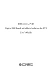
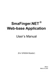
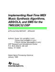
MODEL BVR-32
SIGNAL PROCESSING BOARD
FOR THE PCI BUS
Dalanco Spry
89 Winslow Avenue
Rochester, NY 14620
U.S.A.
Tel: (585) 473-3610
Fax: (585) 271-8380
[email protected]
www.dalanco.com
Copyright (c) 2002 Dalanco Spry
TABLE OF CONTENTS
1. INTRODUCTION
2. INSTALLATION
A. Hardware
B. Software
3. ARCHITECTURE AND MAJOR ELEMENTS
4. OPERATION EXAMPLE
5. HARDWARE FEATURES WITH EXAMPLES
A. SRAM Memory Access
B. Flash Memory Access
C. Direct Digital Synthesis (DDS)
D. TMS320 DSP
1. Start (Set) TMS320 Operation
2. Stop (Reset) TMS320 Operation
3. Set TMS320 to MICROPROCESSOR Mode
4. Set TMS320 to BOOT LOADER Mode
E. PCI Bus to Local Bus MAILBOXES
F. Interrupts
1. PCI Bus to Local Bus
1. PC Host interrupts the TMS320
2. TMS320 interrupts the PC Host
2. Virtex interrupts the TMS320
G. Digital and Analog I/O
1. J10 Generic / IDE connector
2. J11 Additional signals
3. A/D Converter
4. D/A Converter
5. J14 Panel I/O
H. DSP Serial Port
I. DSP Clock/Timers
J. Local RESET
6. TMS320 DSP UTILITIES
A. A300 Assembler
B. D300 Debugger
C. LOADCOFF TI COFF File Loader
7.
FLASH MEMORY PROGRAMMING AND UTILITIES
8.
VIRTEX CONFIGURATION
9.
HOST INTERFACE LIBRARY
10. APPLICATIONS EXAMPLES
A. FFT Software
B. Record and Playback
11. TMS320 in BOOT LOADER Mode
APPENDICES
A. Model BVR-32 Memory Map
B. Emulation Header
C. Texas Instruments C Compiler
REFERENCES
1. INTRODUCTION
This manual is the reference to the Model BVR-32 Digital Signal Processor Board and its accompanying software.
The reference for the Texas Instruments TMS320C32 Digital Signal Processor and its assembly language are the
TMS320C3x User's Guide and the TMS320C32 User's Guide available from TI.
Partial List of References
1. TMS320C3x User's Guide , Texas Instruments Reference no. SPRU031
2. Virtex 2.5V Field Programmable Gate Arrays, Xilinx
3. V350EPC, V360EPC Local Bus to PCI Bridge User's Manual, V3 Semiconductor
2. INSTALLATION
A. Hardware
J7, the BOOT LOADER/MICROPROCESSOR MODE jumper for the TMS320 DSP, must be in the
MICROPROCESSOR MODE position (Jumper OFF).
J8, J9, J16, J13 are NOT jumpered.
B. Software
Please follow the installation instructions in the readme.txt file of the Dalanco Spry installation CD.
3. ARCHITECTURE and MAJOR ELEMENTS
The major elements of the Model BVR-32 are the TI TMS320C32 DSP, the Xilinx VIRTEX FPGA, and the V3
(now QuickLogic) PCI to Local Bus Interface chip. Figure 2 shows the architecture of the Model BVR-32.
Recommendation for New Users of the Model BVR-32.
The mastery of each element is not necessary for doing productive work with the Model BVR-32. Start out
by using one of the default VIRTEX configurations. Follow the software examples, and use the subroutines
provided in the Host Interface Library for handling the PCI to Local Bus interface.
The Virtex configuration determines the interaction of the A/D, D/A, and digital I/O with the Local Bus. It determines
the overall dataflow of the Model BVR-32.
The Default Configuration Revision 1 (BVR1) shown in Figure 1 gives the Model BVR-32 a design similar to most
DSP boards. The local bus is mostly controlled by the TMS320 DSP. Access to analog and digital I/O is done by the
TMS320. The digital I/O is configured as an IDE connector for direct connection to a hard drive in data acquisition
applications.
A second revision (BVR2) will incorporate direct access by the PC Host as well as by the TMS320 DSP. Other
enhancements will be forthcoming. This is, after all, an FPGA.
IDE CONNECTOR
DDS CLOCK
A/D
CONVERTER
'SWITCH'
D/A
CONVERTER
CONTROL
SIGNALS
INTERRUPTS
LOCAL BUS INTERFACE
Figure 1. Generic Virtex FPGA Configuration
TMS320C32
DSP
60 MHZ
4 Channel 12 BIT
A/D CONVERTER
THS1206
DUAL HIGH
SPEED 12 BIT
D/A CONVERTER
AD9765
A/D
Clock
DDS CLOCKOUT
D/A
Clock
GENERAL
PURPOSE /
ATA-IDE I/O
XILINX VIRTEX FPGA
XCV50 (50K GATES)
OR LARGER
DIRECT DIGITAL
SYNTHESIZER
AD9850
AUXILIARY
DIGITAL I/O
60 MHZ CLOCK
LOCAL BUS - 32 bits Data, 26 bits Address
LOCAL
BUS
CLOCK
TMS320C32
DSP
60 MHZ
PCI TO LOCAL
BUS BRIDGE
V360
MASTER/SLAVE
PCI BUS
DSP
SERIAL
PORT
EMULATOR
PORT
STATIC
RAM
512K Bytes
VOLTAGE
SUPERVISOR
--------------------BOOTLOAD/
MICROPROCESSOR
MODE SELECTOR
Figure 2. Dalanco Spry Model BVR-32 FLOW DIAGRAM
FLASH
MEMORY
512K Bytes
LOCAL BUS
ARBITER
4. OPERATION EXAMPLE
The best way to become familiar with the TMS320 aspects of the Model BVR-32 is to use the D300 debugger. To use
D300 and other PC based programs with the Model BVR-32, set J7 to MICROPROCESSOR MODE (Jumper OFF).
For this example, the Virtex FPGA may be configured in the Default Mode, or may be left unconfigured.
We will use D300 to:
1) Display memory.
2) Fill memory with a constant.
3) Write a short program using the Assemble and Substitute commands.
4) Disassemble the program to make sure it is correct.
5) Run the program.
6) Halt the program.
7) Display the result.
Note: In the discussion below, <cr> indicates a carriage return.
Invoke D300:
Type D300 at the MS-DOS prompt. A dash (-) appears as the new prompt.
Make sure the TMS320 DSP is not running. The TMS320 /RESET status bit should be displayed as 0. If not, halt the
DSP:
-h<cr>
Display memory:
To display the first 40h words of memory, type
-d0,3f<cr>
Note that the addressing always points to 32 bit words (DWords).
Fill memory with a constant:
Enter the Fill command and D300 responds with three questions. In the example below, we are filling 1000h locations
with zeroes.
-f<cr>
Enter constant?0<cr>
Starting Address?0<cr>
Number of Locations to fill (HEX)?1000<cr>
Write a short program:
To insert the Reset Vector at location 0, use the Substitute command. The Reset Vector is the address location of the
first instruction in your program. Type
-s0<cr>
The address 0 and its current contents appear and D300 awaits your entry. Type
40
Note: If D300 responds with ???, you made an entry error. Reenter the instruction. D300 provides the next address (in
this example, 1) and waits for your entry. If you don't want to enter anything at that address, press <cr> to move to the
following address. If you exit the Substitute command, type
.<cr>
The dash (-) prompt reappears.
We will continue our program at address 40h, so type
-a40<cr>
Then enter the rest of the program
40 LDP 0
41 LDI 900H,SP
42 LDF @50H,R0
43 LDF @51H,R1
44 ADDF3 R0,R1,R2
45 STF R2,@52H
46 B 46H
47 . <cr>
The instruction at location 41h sets the stack pointer. It is necessary if you later decide to trace through this new
program using the Extended instructions.
Using the Substitute command, let's enter data at locations 50h and 51h.
-s50<cr>
0050 ABCDEF89-0.75<cr>
0051 C0000000-1.05<cr>
0052 12340987-.<cr>
Here we are entering the floating point number 0.75 at location 50h. Note that we entered 0.75, not .75. The leading
zero is necessary.
Disassemble the program:
The following command disassembles the statement at location 40h.
-u40
Continue to press <cr> to disassemble subsequent instructions. Correct any errors using the Assemble or Substitute
commands.
To return to the prompt, enter .<cr>
Run the program:
Enter the Go command to run your program.
-g<cr>
Halt the program:
Enter the Halt command to stop your program.
-h<cr>
Display the result:
SInce you have just performed a high speed floating point calculation, you will probably want to look at the data in its
floating point format. To do this, enter a dot <.> after the Display or Substitute command.
-d.50,52<cr>
or
-s.50<cr>
Does location 52h contain the sum of locations 51h and 50h ?
5. HARDWARE FEATURES
IMPORTANT NOTE on Addressing:
Addresses in PC programs are in units of 8 bit Bytes.
Addresses in TMS320C3x programs are in units of 32 bit words (DWords).
Thus the PC C language statement:
V3PBC_WriteDWord(BVR32handle, 0x400, 0x12345678);
And the TMS320C3x Assembly language code:
RAMLOC
.word 100h
ldi
@RAMLOC, AR2
sti
R0, *AR2
are referencing the same location in memory, ie. 400H(Byte addressing) = 100H(DWord addressing).
In many of the PC program examples, this is emphasized by expressing the PC byte address as DSP address << 2,
where <<2 denotes shift left 2 bits or multiply by 4.
A. SRAM
The Model BVR-32 holds a single block of SRAM (Static Random Access Memory) which starts at address 0. There
are 128K DWords (512K Bytes) of SRAM.
Accessing location 1000h (Dword addressing) in SRAM:
From the PC Host:
V3PBC_WriteDWord(BVR32Handle, 0x1000 <<2, 0x12345678);
From the DSP:
RAMLOC
.word 1000h
ldi
@RAMLOC, AR2
sti
R0, *AR2
Accessing the second Byte at location 0 from the PC Host:
Byte_Val = V3PBC_ReadByte(BVR32handle, 1);
B. Flash Memory
Flash memory appears in the memory space of the TMS320C32 at 900000h and continues for 512K DWords. The
Flash memory data bus is 8 bits (1 byte) wide and is wired to the low byte of the TMS320C32's 32 bit data bus (d0-d7).
The first byte of Flash appears at 900000h, the second byte at 900001h, and the last byte is at 97ffffh. Bits 8-31 appear
'empty' to the TMS320C32 in this memory region.
To read location Address_Offset in Flash memory from the PC Host:
Byte Value = ReadByte(BVR32handle, FLASH_PC + Address_Offset)
From the Address Map in Appendix A, note that FLASH_PC, the base address of the Flash memory, resides at address
0x2000000 in PC space.
To read location 0 from the TMS320 DSP:
FLASHLOC0
.word 900000h
ldi
@FLASHLOC0, AR3
ldi
*AR3, R2
Writing to Flash memory is more complex. Use the Flash proramming utilities described in Section 7. A detailed
explanation of Flash memory may be found in Reference 5.
C. Direct Digital Synthesizer (DDS)
The DDS is a high precision programmable clock which can be used for setting sampling rates and for other purposes.
From the PC, the DDS registers are located at addresses DDS_WCLK, DDS_FQUD, and DDS_RESET.
The program LOADDDS can be used to program the DDS. LOADDDS prompts for the desired output frequency, and
then informs the user of the actual output frequency, which differs from the desired output frequency by an amount not
exceeding the DDS output resolution. On the Model BVR-32 this resolution is 0.015 Hz.
In your own software, use the function AVR32_DDS provided in the Host Interface Library to program the DDS.
64MHz is the input DDS frequency on the Model BVR-32.
From the PC Host:
At the MS-DOS prompt:
>LOADDDS
LOADDDS prompts for the desired output frequency.
In the user's C program:
float BVR32_DDS_INPUT = 64000000.0;
AVR32_DDS (BVR32handle, BVR32_DDS_INPUT, output_frequency);
From the TMS320C32,
See the subroutine program_dds in boot.asm.
From the Virtex FPGA,
This will depend on the configuration of the Virtex FPGA.
D. TMS320C32 DSP Access
1. Start TMS320C32 Operation
The PC instruction to begin TMS320C32 execution is to set bit 0 of the DSP_CONTROL register to 1.
Or use the provided function:
AVR32_StartTMS320(BVR32handle);
2. Halt TMS320C32 Operation
The PC instruction to halt TMS320C32 execution is to set bit 0 of the DSP _CONTROL register to 0.
Or use the provided function:
AVR32_StopTMS320(BVR32handle);
3. Set TMS320C32 to Microprocessor Mode
The PC instruction to set the TMS320C32 to Microprocessor Mode is to set bit 1 of the DSP _CONTROL register to 0.
Or use the provided function:
AVR32_MPModeTMS320(BVR32handle);
4. Set TMS320C32 to Boot Loader Mode
The PC instruction to set the TMS320C32 to Boot Loader Mode is to set bit 1 of the DSP_CONTROL register to 1.
Or use the provided function:
AVR32_BLModeTMS320(BVR32handle);
E. Mailbox Access
The V3 PCI interface chip contains 16 bidirectional mailbox registers for communications of small amounts of data
between the PC Host and the Local Bus. They may be accessed in Byte (1 mailbox), Word (2 mailbox), or DWord (4
mailbox) increments.
Access examples from the PC Host:
Byte_value = V3PBC_ReadRegByte(BVR32handle, V3PBC_MAIL_DATA0);
V3PBC_WriteRegDWord(BVR32handle, V3PBC_MAIL_DATA4, DWorddata);
Access examples from the TMS320 DSP:
V3REGC0
.word 600030h
ldi
@V3REGC0, AR3
sti
R0, *AR3
ldi
*+AR3(1), R1
; Write DWord to Mailbox 0
; Read DWord from Mailbox 4
F. Interrupts
1. PCI Bus to Local Bus Interrupts. Details on the PCI Bus to Local Bus Interrupts may be found in Reference 3.
a. The PC Host generates an interrupt to the TMS320C32 pin on the /INT2 pin.
Example incorporating a mailbox transaction:
Clear any possible pending interrupts.
Enable local interrupts on PCI bus writes to Mailbox 0.
Global Mailbox enable.
Generate the interrupt by writing to the Mailbox.
WriteRegByte(BVR32handle, MAILBOX0,Byte Data);
Please see INTDSP.C and the corresponding TMS320 interrupt handler INTDSP.ASM on the distribution disk.
b. Model BVR-32 interrupts the PC Host's CPU.
Example:
The TMS320C32 DSP first sets the PCI_INT_CFG register.
Then it generates the interrupt by writing to the PCI_INT_STAT register.
See INTPC.ASM and the PC Windows interrupt handler in INTPC.C. The WinDriver documentation (Reference 4) has
more complete information on PC interrupts under Windows.
These interrupts may also be tied to a Mailbox transaction. See the IntMail.c examples on the distribution disk.
2. Other Interrupts to the TMS320C32 DSP
TMS320C32 interrupts /INT0, /INT1, and /INT3 originate from the Virtex FPGA. In the default configuration BVR1,
they are used as follows:
/INT0 IDE Event Interrupt
/INT1 A/D FIFO Interrupt
/INT3 not used
G. Digital and Analog I/O
1. J10 - General Purpose/IDE Connector
The general pin functions for J10 are listed below:
PIN 1
OUTPUT
PIN 3
BI-DIRECTIONAL
PIN 5
BI-DIRECTIONAL
PIN 7
BI-DIRECTIONAL
PIN 9
BI-DIRECTIONAL
PIN 11
BI-DIRECTIONAL
PIN 13
BI-DIRECTIONAL
PIN 15
BI-DIRECTIONAL
PIN 17
BI-DIRECTIONAL
PIN 19
GND
PIN 21
INPUT
PIN 23
OUTPUT
PIN 25
OUTPUT
PIN 27
INPUT
PIN 29
OUTPUT
PIN 31
INPUT
PIN 33
OUTPUT
PIN 35
OUTPUT
PIN 37
OUTPUT
PIN 39
INPUT
PIN 2
PIN 4
PIN 6
PIN 8
PIN 10
PIN 12
PIN 14
PIN 16
PIN 18
PIN 20
PIN 22
PIN 24
PIN 26
PIN 28
PIN 30
PIN 32
PIN 34
PIN 36
PIN 38
PIN 40
GND
BI-DIRECTIONAL
BI-DIRECTIONAL
BI-DIRECTIONAL
BI-DIRECTIONAL
BI-DIRECTIONAL
BI-DIRECTIONAL
BI-DIRECTIONAL
BI-DIRECTIONAL
KEY
GND
GND
GND
NC
GND
INPUT
NC
OUTPUT
OUTPUT
GND
J10 is configured as follows when the Virtex FPGA is in the default configuration BVR1:
PIN 1
HRESET(O)
PIN 2
GND
PIN 3
IDED7(IO)
PIN 4
IDED8(IO)
PIN 5
IDED6(IO)
PIN 6
IDED9(IO)
PIN 7
IDED5(IO)
PIN 8
IDED10(IO)
PIN 9
IDED4(IO)
PIN 10
IDED11(IO)
PIN 11
IDED3(IO)
PIN 12
IDED12(IO)
PIN 13
IDED2(IO)
PIN 14
IDED13(IO)
PIN 15
IDED1(IO)
PIN 16
IDED14(IO)
PIN 17
IDED0(IO)
PIN 18
IDED15(IO)
PIN 19
GND
PIN 20
KEY
PIN 21
DMARQ(I)
PIN 22
GND
PIN 23
DIOW(O)
PIN 24
GND
PIN 25
DIOR(O)
PIN 26
GND
PIN 27
IORDY(I)
PIN 28
NC
PIN 29
DMACK(O)
PIN 30
GND
PIN 31
INTRQ(I)
PIN 32
IOCS16(I)
PIN 33
DA1(O)
PIN 34
NC
PIN 35
DA0(O)
PIN 36
DA2(O)
PIN 37
CS1FX(O)
PIN 38
CS3FX(O)
PIN 39
DASPWA(I)
PIN 40
GND
(O) means that the signal is an OUTPUT from the Model BVR-32.
(I) means that the signal INPUT into the Model BVR-32.
(IO) means that the signal is bi-directional.
NC means No Connection.
IDED0-IDED15 (IO) are bits 0-15 of the the buffered data bus from the Virtex FPGA
DA0-DA2 (O) are the buffered address lines 0-2 from the Virtex FPGA
J10 is configured as an IDE connector under the default configuration. Under BVR1, the following IDE signals are not
connected: DMARQ, DMACK, DASPWA, IOCS16.
2. J11 - Additional Signals
J11 signals are as follows. They do not depend upon the Virtex configuration:
PIN 1
PIN 3
PIN 5
PIN 7
PIN 9
NC
+5V
NC
H3
RW
PIN 2
PIN 4
PIN 6
PIN 8
PIN 10
GND
NC
NC
TCLK0
STRB
These signals are buffered TMS320 clock and control signals.
3. A/D Converter
The A/D Converter is the 12 bit 4 channel Texas Instruments THS1206..
In the Virtex BVR1 Configuration, it is wired to the upper 12 bits 15-4 of a 16 bit data word.
It is clocked by the signal A/DClock from the Virtex FPGA.
Please refer to the TI documentation and examples on the distribution disk.
4. D/A Converter
The D/A Converter is the Analog Devices 12 bit dual channel AD9765, which is capable of being clocked to 25 MSPS
and higher frequencies..
In the BVR1 Configuration, it is wired to the upper 12 bits 15-4 of a 16 bit data word.
It is normally clocked by the signal D/AClock from the Virtex FPGA.
Keep in mind that the 12 bit A/D and D/A converters are wired to bits 15-4 of the data bus in the BVR1 configuration
when reading and writing to these devices. Data and configuration values must be shifted by 4 bits.
The following examples of A/D Converter and D/A Converter usage may be found on the distribution disk.
1. AD-DA pass-through example using the Virtex BVR1 configuration: BVR1, ADDA.C, ADDA.ASM, LOADDDS
2. Digital Filter uses Virtex to implement the filter: FILTER, LOADDDS
3. 4 Channel A/D input: BVR1, THS4.ASM, LOADDDS
5. J14 - Panel I/O
4 I/O lines, 2 input and 2 output, are available at the DB-25 connector. They are connected to the Virtex FPGA via a
buffer. The table below describes the signal functions under the Virtex BVR1 configuration.
J14 DB-25 Connector Signals
PIN 1, 2
PIN 3,4,5
GND
GND
PIN 7
PIN 8
TTL-OUT4(O)
TTL-OUT2(O)
PIN 12,13
GND
PIN 14
PIN 15
PIN 16
PIN 17
PIN 20
PIN 21
PIN 24
PIN 25
TTL-OUT4 is an OUTPUT from the Model BVR-32
TTL-OUT2 is an OUTPUT from the Model BVR-32
TTL-IN3 is an INPUT to the Model BVR-32
TTL-IN1 is an INPUT to the Model BVR-32
A/D is an INPUT to the Model BVR-32
D/A is an OUTPUT from the Model BVR-32
H. DSP Serial Port
The buffered serial port of the TMS320C32 is available at J12.
PIN 1
PIN 3
PIN 5
CLKX
FSX
DR
Test configuration
Connect the following:
CLKR to CLKX
FSR to FSX
DR to DX
Run SERTEST.ASM on the distribution disk.
PIN 2
PIN 4
PIN 6
FSR
DX
CLKR
A/D - BINP (I)
A/D - BINM(I)
A/D - AINP(I)
A/D - AINM(I)
TTL-IN3(I)
TTL-IN1(I)
D/A1(O)
D/A0(O)
I. Clock/Timers
There are two clock/timer pins on the TMS320C32. They are TCLK0 and TCLK1.
TCLK0 is available as Clock/Timer/IO on the Digital connector J11.
TCLK1 is connected to the Virtex FPGA.
Test files for the TCLK0 and TCLK1 are TT0.ASM and TT1.ASM:
J. Local RESET
The Local RESET pulse is a signal which sets the devices on the Model BVR-32 to a known idle state. It is generated
after power-up after the onboard voltage supervisor has decided that the voltage supply of the Model BVR-32 is stable
and at the correct level.
In the Default condition, known as NOCLEAR, the Local RESET pulse is dependent on no other stimulus. For
example, a filter passing data from the A/D to D/A will continue to run even if Windows is restarted, or the PC reset
button is pushed.
The LRST# signal from the V360EPC PCI chip may also generate the Local RESET pulse. This is the CLEAR
condition. The Model BVR-32 is set to a known idle state each time Windows is restarted, or the PC reset button is
pushed.
Setting the Local RESET pulse to NOCLEAR:
V3PBC_WriteByte(BVR32Handle, NOCLEAR_ON_LRST ,0);
Setting the Local RESET pulse to CLEAR:
V3PBC_WriteByte(BVR32Handle, CLEAR_ON_LRST ,1);
6. TMS320 DSP UTILITIES
A. A300 Assembler
A300 is the assembler for the Model BVR-32.
The Command line
>A300 {-output mode} infile
The output mode can be:
c COFF -- COFF format. This output may be read directly into the MODEL BVR-32 using LOADCOFF.
a ascii -- ASCII format. This output may be used as an array in the user's C language programs.
f flash -- Flash memory format. This output is used to generate a file to be written to Flash memory.
If the output mode is c, a COFF Version 2 .OUT file is generated
If the output mode is a, a .ASC file is generated.
If the output mode is f, a .FLA file is generated.
INSTRUCTIONS
Label:
Label:
Opcode Operand
Opcode Operand
;comment
;comment
;comment
DIRECTIVES
.aorg <position pointer>
Changes the current position pointer to the one specified. This feature is not compatible with the TI Assembler, which
relies on its Linker for placement of code and data segments in memory.
Example:
.aorg 10h
.space <number of memory locations>
Advances the current position pointer by the specified number of words.
Example:
.space 100
.word <data word>
Stores the data word.
Example:
SinTab .word
.word
0
abcd324h
.float <floating point data word>
Stores the data word in floating point format. It is useful for storing sine tables, window and filter coefficients, etc..
Example:
.float
.float
1.070098e-1
0.98120
; NOT .98120 !
.end
Ends assembly, no further instructions are recognized. This directive is not necessary if the file ends in a blank line.
Example:
.end
.set
Equates a variable to an expression.
Example:
Here
.set 400h
The following TI Linker related directives have no effect on the assembly process:
.data, .text, .global
RESERVED WORDS
All of the TMS320 Opcodes and Assembler directives are Reserved Words. If they are used as labels or variable
names, a "Syntax Error" will result.
Example:
End:
End1:
br
br
End
End1
; illegal because ".END" is a directive
; OK
DIFFERENCES BETWEEEN THE TI AND DALANCO ASSEMBLERS.
A300 has the following requirements:
1.
Labels must be followed by a colon ':'.
Example:
here:
2.
nop
br
@here
Comments must begin with a semicolon ';'.
3.
Three operand instructions must have a '3' in their opcode.
Example:
mpyf
r0,r4
; 2 operand instruction
mpyf3
r0,r4,r7 ; 3 operand instruction, OK
mpyf
r0,r4,r7 ; SYNTAX ERROR
4.
Source and destination operand must be explicitly written.
Example:
neg
neg
r0,r0
r0
; OK
; SYNTAX ERROR
EXAMPLES:
To create an ascii file.
>A300 -a test
To create a COFF file and load the Model BVR32.
>A300 -c test
>LOADCOFF test.out
To create an executable to be loaded to Flash memory
>A300 -f test
>LOADF test
B. D300 Debugger
D300, the debugger, is the basic tool for 'manually' controlling the Model BVR-32 board.
Syntax: >D300 <cr>
The commands are explained below:
A - Assemble
The A command places TMS320C3x instructions into memory one line at a time. As each line is assembled, its
corresponding object code is displayed on the screen.
-ab90 <cr>
B90 b 7b4h <cr>
B92 sti r0,@100h<cr>
B93 rolc r2 <cr>
Press <cr> to assemble the next instruction. D300 displays the assembled object code. Exit by entering a dot (.)
followed by <cr>.
B - Boot Loader Mode
Places the TMS320C32 on the Model BVR-32 in Boot Loader Mode
by setting the MCBL/MP pin HIGH.
-b<cr>
C - Copy
The Copy command moves data from one block of memory (the source) to another (the destination). D300 prompts the
user for the start and end addresses of the source block and the beginning address of the destination block. The memory
must be offchip, ie external to the TMS320.
D - Display
The D command displays memory in hexadecimal or floating point notation. Syntax: Daddress1,address2 or
D.address1,address2 where address2 is greater than address1.
-d54,110<cr>
displays all memory locations between 54h and 110h in hexadecimal format.
-d.54,110<cr>
displays all memory locations between 54h and 110h in floating point format.
To pause the display, enter <Cntrl-s>.
To terminate the display prematurely, enter <ESC>.
F - Fill
The F command fills a portion of memory with a 32 bit constant. The user is in turn prompted for the constant in
hexadecimal or floating point notation, the first address at which the constant is to be placed, and the number of
memory locations to be filled.
-f Enter constant in hex ? 11200 <cr>
Starting Address in hex ? BCD <cr>
Number of Locations to Fill (hex) ? 300 <cr>
This example fills the 300h locations in memory starting at BCDh with 11200h.
G - Go
The G command sets the TMS320 set/reset pin, thus setting the processor into operation.
-g<cr>
The TMS320 is set into operation and continues to run until the Halt command is issued.
H - Halt
The Halt command resets the TMS320 set/reset pin. This halts TMS320 operation.
-h<cr>
MP - Microprocessor Mode
Places the TMS320C32 on the Model BVR-32 in Microprocessor Mode
by setting the MCBL/MP pin LOW.
-mp<cr>
Q - Quit
Used to exit the D300 program.
-q<cr>
R - Read from Disk
This command reads the contents of a COFF Version 2 file into the Model BVR-32 memory. This command serves the
same function as the LOADCOFF program.
-rb:crypto.out<cr>
reads the file b:crypto.out into memory.
S - Substitute
The Substitute command allows the replacement of the 32 bit word at each memory location. The input may be in
hexadecimal integer or floating point format. Floating point numbers are converted to the TMS320C3x floating point
format.
-s556<cr>
556 111CA321-8000<cr>
557 A098AD37-1.07e-3<cr>
558 ffff0000-0.987<cr>
559 C8000000-.<cr>
In the above example the user has replaced the words at addresses 556h through 558h. Enter <cr> to modify the next
memory location. Exit by entering a dot (.) followed by <cr>. In the case of fractional floating point numbers, a zero
must be the leading character, ie enter 0.123, not .123.
U - Unassemble
This command disassembles memory contents into their TMS320C3x instruction codes one line at a time. Enter <cr> to
disassemble the next memory location. Exit by entering a dot (.) followed by <cr>.
-u5<cr>
5 ROR R5 <cr>
6 NEGI 100,R5 <cr>
8 LDI *-AR1(IR0),R3 . <cr>
V - View
The View command continuously scans the desired range of offchip RAM. In this way one may examine areas of
memory during Model BVR-32 operation. Input syntax is similar to Display.
-v400,41f<cr>
for hexadecimal display.
-v.400,41f<cr>
for floating point format display.
W - Write to Disk
This command writes the contents of memory to a file in the COFF Version 2 format.
-wtest.out<cr>
Starting Location in memory (Hex) ?10<cr>
Number of Locations to write to file ?12<cr>
writes memory locations 10h to 22h to test.out
C. LOADCOFF COFF File Loader
LOADCOFF loads COFF version 2 .OUT files created by A300 or by the TI Linker into the Model BVR-32.
LOADCOFF gives you the ability to control TMS320 execution. It may also be used to convert COFF files to .ASC or
.FLA format files.
>LOADCOFF {preload options} {postload options} {output options} infile
Preload Options
-1h
Before loading the binary fle, LOADCOFF will Halt the TMS320.
-1hg
Before loading the binary file, LOADCOFF will not change the TMS320 Start/Halt status.
Postload Options
-2hg
After loading the binary file, LOADCOFF will not change the TMS320 Start/Halt status.
-2g
After loading the binary file, LOADCOFF will Start the TMS320.
The following option sets are equivalent and are the default operation of LOADCOFF:
>LOADCOFF TEST
>LOADCOFF -1h -2hg TEST
>LOADCOFF -1h
TEST
In the next example, the TMS320 is NOT halted during the loading process:
>LOADCOFF -1hg
TEST
Caution must be observed when loading a board with a running TMS320. Do not load a memory location which the
TMS320 is currently accessing!
Output Options
Example 1:
>LOADCOFF TIFFT
loads the contents of TIFFT.OUT into the correct locations on the Model BVR-32.
Example 2:
>LOADCOFF -A TIFFT
reads the contents of TIFFT.OUT and produces TIFFT.ASC for inclusion as array(s) in the user's C program.
Example 3:
>LOADCOFF -F TIFFT
reads the contents of TIFFT.OUT and produces TIFFT.FLA for subsequent programming of the Model BVR-32's
onboard Flash memory.
7. FLASH MEMORY PROGRAMMING and UTILITIES
The Model BVR-32 has 512K Bytes of Flash memory. Flash memory generally contains initialization code, an entire
application, and/or data that your program might require.
The Flash memory resides in the TMS320C32's memory space starting at address 900000h. This is the Boot 3 address
associated with a low /INT2 input at startup.
To program Flash memory with your TMS320 executable:
1) Write the code that you wish to place in the Flash memory. See the examples on the distribution disk.
2) Assemble your code with the '-f' flag.
>A300 -f myprog
This will create the file myprog.fla.
3) Erase any code that might be on the Flash memory using the SECTORE program.
>SECTORE
SECTORE will prompt you for the sectors to be erased. There are 8 sectors labelled 0-7 each occupying 64K Bytes.
You will need to erase Sector 0, and also succeeding sectors if 'myprog' is a large program.
4) Program the Flash memory with your new executable code.
>LOADF myprog
To write an array of data to Flash memory from a Xilinx HEX file, use the LFV program. Make sure that the target
sectors are erased.
Example: To write the Xilinx HEX file test.hex to location 10000h, make sure that sectors1 and 2 (and possibly more
if you are using a larger Virtex device) are erased.
LFV -10000 test.hex
The LFVCHK program checks Flash memory against a Xilinx HEX file
LFVCHK -10000 test.hex
checks that the previous operation has been successful.
RDFLASH and WRFLASH are Flash memory reading and writing utilities. Be sure that the location written to by
WRFLASH has been previously erased.
FLASHE erases the entire Flash memory.
8. VIRTEX CONFIGURATION
LOADVIR loads the HEX file containing the Virtex configuration information into the Model BVR-32's Virtex FPGA.
The HEX file is created by the Xilinx PromFile Formatter. See the Virtex Configuration for the Model BVR-32
document. The default configuration BVR1.HEX is loaded as follows:
>LOADVIR BVR1
Upon successful loading LOADVIR will respond with a DONE message and indicate the number of bytes loaded.
9. HOST INTERFACE LIBRARY
This section describes the utility functions for controlling the Model BVR-32 that are linkable to the user's software.
These routines run on the PC Host and assume the user's use of a Windows 32 bit Operating System (Windows
98/NT/2000).
The Dalanco provided functions are in AVR32__.LIB. The accompanying C header is AVR32.h.
Set TMS320C32 to Boot Loader Mode
AVR32_BLModeTMS320(BVR32handle);
Set TMS320C32 to Microprocessor Mode
AVR32_MPModeTMS320(BVR32handle);
Start TMS320C32 Operation
AVR32_StartTMS320(BVR32handle);
Halt TMS320C32 Operation:
AVR32_StopTMS320(BVR32handle);
Program the DDS:
AVR32_DDS(BVR32handle, (double)Input_frequency, (double)Output_frequency);
Configure the Virtex device:
AVR32_LoadVIRTEX(BVR32handle, HEXFileName);
10. APPLICATIONS EXAMPLES
A. FFT Software
The FFT routine provided was downloaded from the TI website and may also be found in the TMS320C3x User's
Guide:
FFT.ASM : The above FFT routine but modified for use with the A300 Assembler. There is no link step when using
the Dalanco tools. Therefore the sine table is included as part of FFT.ASM.
In each case the real values are loaded in at 1400H and the imaginary values are loaded in at 1500H. Thus locations
1400H through 15FFH are reserved for input.
The results of the FFT replace the input.
Example: a 'manual' FFT in D300.
-g <cr>
-h
-d1400,14ff <cr>
; Start TMS320
; Stop
; look at results
The FFT routine outputs STARTING and COMPLETED words to Mailbox 0. This is to inform the PC Host as to what
the TMS320 is doing.
Example: FFT in a user's program.
If you program in C, see the FFT300.C file on the distribution disk. This program is also on your disk in executable
form.
B. Record and Playback
RECORD
This program transfers continuous data from the A/D Converter to the PC’s hard disk. The maximum amount of data
which may be recorded is dictated by the remaining free space on the disk. The maximum direct-to-disk sampling rate
depends upon the computer and type of hard disk used. The RECORD program prompts the user for the following
data:
2.Sample Rate.
3.Disk file name (for writing).
PLAYBACK
This program transfers data from the PC's hard disk to the Model BVR-32 for output to the D/A converter. The
program prompts for the following data:
1.Sample Rate.
2.Disk file name (for reading).
11. BOOT LOADER MODE
The jumpers are set as follows for Boot Loader mode:
J7 -
Jumper installed
In this mode the TMS320C32 begins operation at power-up. The TMS320C32 is set for Boot Loader operation (the
MCBL/MP pin of the TMS320C32 is set high) and your application is loaded from the Flash memory. After the
loading process, the TMS320C32's program counter jumps to 1000h, where normal operation of your program begins.
Steps for creating software for Boot Loader Mode operation.
Assume you have created and debugged a program in the PC environment with the Model BVR-32 in Microprocessor
Mode which you wish to 'port' to Boot Loader Mode.
Step 1.
Make the changes to your software which are needed for Boot Loader Mode operation. Changes are needed because
addresses 0-FFFh are reserved for Boot Loader operations and cannot be used by your program (at least, not initially).
Your program will need to start at 1000h.
If you are using interrupts, you will probably need to relocate the Interrupt Vector Table from 0 to an unused block of
addresses above 1000h.
Example on disk of the changes:
SA_PRG0.ASM --> SA_PRG1.ASM
Step 2.
Create a .FLA file from this program and load it to the Flash memory.
>A300 -F SA_PRG1
Erase Flash Memory.
>SECTORE
Load your new program into Flash memory.
>LOADF SA_PRG1
You can test the program without actually setting the board jumper J7 to Boot Loader Mode. This allows for rapid
modification and testing of your program. Leave the board in Microprocessor Mode (J7 removed).
Set the MCBL/MP pin of the TMS320C32 to Boot Loader operation by entering the 'b' command in D300.
Next, using D300, start the board by entering the 'g' command. Since the TMS320C32 is set for Boot Loader operation,
the software will be loaded from Flash memory and then run, just as if J7 were set in Boot Loader Mode.
>D300
-b
-g
Finally, after the program has been debugged, the last step is to set J7 for Boot Loader Mode, power up the board, and
watch your application run.
APPENDIX A
MODEL BVR32 ADDRESS MAP 22-JUL-02
From PC
RAM
FLASH
PROGRAM VIRTEX
VIRTEX_ADDR
VIRTEX_STAT
VIRTEX_WRCS
VIRTEX_BUSY
VIRTEX_PROG
PULSE VIRTEX
CLEAR ON LRST
NOCLEAR ON LRST
VIRTEX INTERNALS
BYTE Address
0 - 0x7FFFF
0x2000000 - 0x21FFFFF
0x3000000
0x3000000
0x3000004
0x3000004
0x3000008
0x3000008
0x300000C
0x300000C
0x300000C
A23 A22 A21
00x
10x
110
0x1000000 - 0x1FFFFFF
01x
111
DDS
DDS_WCLK
0x3800008
DDS_FQUD
0x3800004
DDS_RESET
0x380000C
DSP_STATUS
(bits1-0) for /RS, BLMP
DSP_CONTROL 0x3800000
DSP_STATUS
0x3800000
V3 REGISTERS
110
110
110
Word Size
DWORD usually
BYTE
DWORD
BYTE read
BYTE write
BYTE read
BYTE write
BYTE read
BYTE write (=1)
BYTE write (=0)default
DWORD usually
BYTE write
BYTE write
BYTE write
111
BYTE write
BYTE read
From DSP
RAM
FLASH
PROGRAM VIRTEX
VIRTEX_ADDR
VIRTEX_STAT
VIRTEX_WRCS
VIRTEX_BUSY
VIRTEX_PROG
PULSE VIRTEX
VIRTEX INTERNALS
IDE INTERFACE
AD Converter
DA Conv. Ch 0
DA Conv. Ch 1
INOUT PINS
DWORD Address
0 - 0x1FFFF
0x910000 -
A23 A22 A21
000
100
11x
0xC00000
0xC00001
0xC00001
0xC00002
0xC00002
0xC00003
0x200000 0x220000
0x220001
0x220003
0x220002
11x
001
0x600000
DWORD
DWORD
DWORD
DWORD
DWORD write
DWORD write
*
*
*
*
*
DDS
DDS_WCLK
0xA00001
DDS_FQUD
0xA00002
DDS_RESET
0xA00003
PC SPACE
DSP_STATUS
(bits1-0) for /RS, BLMP
DSP_CONTROL
0xA00000
DSP_STATUS
0xA00000
V3 REGISTERS
Word Size
DWORD
DWORD write
DWORD write
DWORD
101
DWORD write
DWORD write
DWORD write
010
101
DWORD write
DWORD read
011
DWORD
APPENDIX B
EMULATION HEADER
J5 is the emulation header, where the Model BVR-32 is used as the target system.
EMU1
EMU0
EMU2
+5V
EMU3
H3
o o GND
o o GND
o o GND
o o KEY
o o GND
o o GND
APPENDIX C
TEXAS INSTRUMENTS C COMPILER
The Texas Instruments Optimizing C Compiler for the TMS320C3x and TMS320C40 may be used with the Model
BVR-32. The advantages of using the C compiler are clear:
Rapid creation of applications, as well as easier maintenance of code.
Existing algorithms coded in C for other platforms may be recompiled to run on the TMS320C3x.
The C-COMPILER subdirectory of the distribution diskette contains the examples and batch files needed for a quick
start in using the C compiler.
CTEST.C is a test C program.
DOCL30.BAT is the batch file for compiling and linking, and for loading the program to the Model BVR-32. Modify
to conform to your own system setup.
CTEST.CMD is the Linker command file called by DOCL30.BAT. It specifies the memory map of the Model
BVR-32. Note the allocation of a small 'window' of memory for variables shared by the PC and TMS320C32.
Compile and link the program
DOCL30 CTEST
Be sure that the Linker produces a Version 2 COFF file as its output. Run D300 and trace through the program.
If you don't have the C compiler but would like to trace through the code created by the C compiler, type
LOADCOFF CTEST
and then use D300.
REFERENCES
1. TMS320C3x User's Guide, Texas Instruments Reference no. SPRU031
2. Virtex 2.5V Field Programmable Gate Arrays, Xilinx
3. V350EPC, V360EPC Local Bus to PCI Bridge User's Manual, V3 Semiconductor
4. WinDriver Developer's Guide, Jungo, 2000
5. AM29F040 Flash Memory, Advanced Micro Devices, Inc. 1994