1
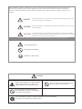
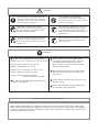
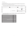
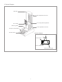
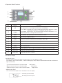
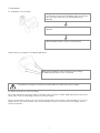
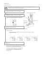
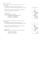
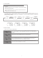
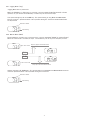
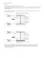
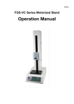
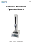
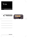
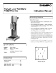
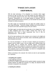
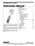
90000
Vertical Force Test Stand
FGS-100E-H/L
Operation Manual
Please read carefully before using this product.
Read carefully "Safety Precautions" and Handling Instructions.
Use appropriately as directed.
NIDEC-SHIMPO CORPORATION
Before Installation, Operation or Maintenance, be sure to read carefully this Operation Manual and use the equipment as
directed. Use the equipment after carefully reading all the caution items, safety information, and other discriminations.
In this User's Manual, the Safety Awareness Items are divided into three different categories: "Danger", "Warning" and
"Caution".
DANGER
This symbol indicates if you ignore the contents mentioned and improperly operate, it may
lead to serious injury from a potential fire.
WARNING
This symbol indicates a potential dangerous situation that could produce a serious injury if
improperly handled.
CAUTION
This symbol indicates a potential situation that could produce a minor injury or damage to
material if it is improperly handled. However, depending upon the situation, there could be a
possibility that it may cause more serious results.
Protection categories are explained and separated by the following symbols.
Proceed with Caution
Not Allowed -Prohibited
Mandatory- Must Follow
WARNING
Heavy! Take sufficient care while handling.
Ensure stand is placed on a flat, level,
stable surface that can support the unit.
Do not operate in areas where explosive
gases or vapors may be present.
Do not touch the running, inner parts.
Keep appendages and loose clothing away
from running, moving parts.
Do not attempt to inspect or perform maintenance on the unit with the
electrical cord connected to a power source.
1
CAUTION
Do not install in a high humidity
environment or near where water may
be present. Electric shock may occur if
water is encountered.
If a loud noise is created from the unit
during operation, check the mounting of
the gauge or level of the stand. If noise
persists, contact the factory.
Hold power plug while removing the
power cord. Do not pull or put tension on
the cord. Doing so could result in cord
damage and electric shock.
Do not scratch, damage, cut, over-turn,
pull, twist, or bundle the power supply
cord. The electric power cord may be
broken and may cause electric shock, fire
or accident.
Use only matching electrical sockets. Do
not alter the power connector in order
to fit an unmatched socket. Shock or fire
could result.
Confirm that the power supply is the same
voltage rating as the displayed voltage
rating on the unit.
Mandatory
Do Not Use in Below Mentioned Locations.
Take care that the Force Gauge Cable is
not caught in the moving parts. This can
be prevented by properly securing the
cable so that it cannot come into contact
with the moving parts.
① Where water, oil or chemicals may come in contact.
② Where there is ample amounts of dust.
③ Where condensation may emerge.
④ Where a fire or explosion may exist or occur.
Mount the Force Gauge to the Test Stand
with the Test Stand's power switch in the
off position.
⑤ Where vibration of machinery exists.
⑥ Where temperatures will go outside
of 32 oF to104 oF (0oC to 40oC).
Do Not adjust the limit knobs while the Test
Stand is moving.
Do not clean with flammable liquids such as
thinner and gasoline.
Ensure that the green earth grounding wire
of the power cord is grounded.
Installation of Digital Force Gauge FGV Series
While installing the Digital Force Gauge FGV Series to the Test Stand FGV Function Setting F06
Outer Parts Output Switchover Setting is to be performed by the Over Load Output (over) Setting.
If setting is performed using the Comparator Output, then with the Force Gauge Over Load (Excess
Load), the Stand does not Stop.
2
Index
1. Before Use
1.1. Force Gauge Installation
4
4
1.2.Inspection of Included Accessories
4
2. Specification
5
3. Product Diagram
6
4. Operation Panel Functions.
6
5. Preparation
8
5.1. Installation of Force Gauge.
8
5.2. Cable connection to the Force Gauge.
8
6. Operation.
9
6.1. Basic Movement
9
6.2. Speed unit change
10
6.3. Changing Mode
11
6.4. Movement Mode
11
6.4.1 Jogging Mode. (JOg)
12
6.4.2 Manual Mode. (MAU)
12
6.4.3 1 Cycle Mode. (SIg)
13
6.4.4 Continue Mode. (CON)
14
6.5. Speed
15
7. Display Error
16
8. Outer Dimensions.
17
9. Trouble Shooting.
18
3
1. Before Use
1.1. Force Gauge Installation
This Shimpo Instruments FGS-100E Test Stand is to be installed with a Shimpo Instruments Digital Force Gauge Series FGV and is
able to perform all types of Load Tests. Related to its execution from installation to measurement, utilize the following procedure. If
encountering issues, check the Trouble Shooting section of this manual.
Confirmation before Use.
Connection.
Installation of Force Gauge
Issues
Trouble Shooting.
1.2.Inspection of Included Accessories
Name of Product.
Quantity.
1
1
1
4
2
1
1
1
1
FGV Connecting Cable (2m).
Power Supply Cable
Cable Clip
Socket Bolt (M4 x 8) for Installing Gauge to Sta
Socket Bolt (M6 x 12) for Test Jig Installation.
Allen Key Spanner for M6t.
Allen Key Spanner for M4
Operation Manual
Guarantee
4
Measurement Mode Separate
Operation Method.
2. Specifications
Series
Model
FGS-100E-L
FGS-100E-H
Low Speed Specifications
High Speed Specifications
Measuring Load
500N(50kgf) (112.4 lbf)
Load Resistance
500N(50kgf) (112.4 lbf)
Forwarding Speed
Display
FGS-100E
6-180mm/min(0.23-7.00in/min)
20-600mm/min(0.78-23.60in/min)
Speed Settings
Set the Speed through Operation panel.
Speed Accuracy
± 5%
Stroke
400mm (15.75in)
Display Parts
LCD 3 Digits indicates movement speed, Operation Mode.
Movement Speed
Operation Mode
Input
6-180mm/min(0.23-7.00in/min)
20-600mm/min(0.78-23.60in/min)
Manual (MAU), Jogging (JOG), 1 Cycle (SIG), Continuous (CON).
Over Load Input
Stops by FGV Over Load Signal
Measurement Table
93 × 150mm(3.66 × 5.91in)
Temperature Range
0 ~ 45° (No Condensation) 32 to 113° F
Power Supply
AC100 ~ 230V ± 10%
Weight
Approx.20kg(40.1lbs)
Outer Dimensions
220 × 680 × 358mm (8.7 × 26.8 × 14.1in)
Corresponding Force Gauge
FGE-0.5 ~ 100
5
FGV-0.5 ~ 100
3. Product Diagram
Cable Clip
Upper Adjustable Limit Knob
Force Gauge Mounting Bracket
Force Gauge
Measuring Table
Lower Adjustable Limit Knob
Emergency Stop Switch
Operation Panel
Backside Diagram
Fuse
Power Switch
Power Cable Outlet
FGV Connecting Cable
6
4. Operation Panel Functions
5
1
6
8
2
10
11
3
7
4
1
No.
Names
1
UP
2
DOWN
3
MAX
4
5
6
7
8
9
10
11
MODE
Function
Set Movement Speeds for Manual (MAU), JOGGING (JOg) Modes and during PUSH/
PULL Operation in 1 Cycle (SIg) and Continuous (CON) Modes.
inch/min Mode : Pressed once , the movement speed increases/decreases by 0.01
if pressed continuously , it changes at the rate of 0.1 .
mm/min Mode : Pressed once , the movement speed increases/decreases by 1 ,if
pressed continuously , it changes at the rate of 10 .
Overrides to the maximum speed value possible of the Stand's motor when pressed.
Once released, the speed returns to the previous set value.
Scroll through the Modes (MAU)
LCD
Displays the condition of Movement Speed, Mode, Alarms. Etc.
PULL
Starts the Operation of PULL Direction
PUSH
Starts the Operation of PUSH Direction
STOP
Stops Test Operation
MAX_LED
Pressing MAX Key, when the Movement Speed is at Maximum, the Lamp lights.
PULL_LED
During PULL Operation it flashes
PUSH_LED
During PUSH Operation it flashes
LCD Normal Display
1) Sub Display Parts:
Presently selected Operation Mode is displayed at the top Sub-Display of LCD.
Limit Position, Over Load condition, or when the Emergency Stop is ON, the Operation Mode and all the Indicators
light-up alternately.
① Limit Position Reached in Operation Mode
② Over Load Occurrence in Operation Mode
LMT Flashes
OVR Flashes
③ When Emergency Stop is ON in Operation Mode
EMg Flashes
2) Main Display Parts:
The set movement speed value is indicated in the main display.
Sub Display (Operation Mode)
Main Display (Movement Speed)
7
5. Preparation
5.1. Installation of Force Gauge
Using the Allen wrench spanner provided in the
accessories, remove the installation bolts connecting
the Test Stand and the Force Gauge Mounting
Bracket
Attach the Force Gauge to the Force Gauge Mounting
Bracket.
With Installation Bolts, secure to the bracket.
※ Attach the Force Gauge to the Mounting Bracket.
With the 4 Installation bolts, install the Force Gauge
and Mounting Bracket to the Test Stand
Possible Force Gauges to install on the FGS-100E is the FGV Series Force Gauges
5.2. Cable connection to the Force Gauge.
Insert the attached connecting cable to the back-side connector of FGS-100E Stand and connect the
other side to the corresponding connector of Force Gauge.
If this communication cable is not connected, the automatic stop function of the Stand due to a Force
Gauge sensor over load condition may not be available. In order to protect the Force Gauge, ensure
proper connection.
8
6. Movement
6.1. Basic Movement
Take sufficient care while aligning, as there is potential of catching a hand, finger or
clothes in the Stand which would cause injury.
Test Stand Power Cord is connected to outlet as well as
Force Gauge power Adapter. Turn on Force Gauge.
(Example) Tension Test of Wire.
Test Stand Power Cord is connected to outlet as well as
Force Gauge power Adapter. Turn on Force Gauge.
Once on, the display will indicate the model number,
then will show the speed setting as shown below.
Power Supply.
Crimped Terminal.
Wedge Chuck
(OPTIONAL)
MODE (Measuring Method) Setting.
Select the Movement Mode, matching to your required test needs.
Movement Mode
Press the PUSH Key or PULL Key to cycle through Manual, Jogging, 1Cycle or
Continuous movement.
Manual Mode Display.
Jogging Mode Display.
1 Cycle Mode Display.
Continuous Mode Display.
MAU
JOg
SIg
CON
Start Measuring
With the PUSH or PULL Key, Measurement can be started.
For details refer to the Movement Mode Operation described
later. Load Tests as follows can be performed.
Press Test - Tensile Strength Test - Weld Strength
Test - Peel off Test - Absorption Power Test
Resistance Power Test - Uncapping (Seal) Test Punching Test.
9
6.2. Speed unit change
① When changing the operation speed to inch/mm from mm/min
a) Power OFF
Turn ON the stand while holding down the “MAX” key.
Keep pressing the “MAX” key until the display shows JOG mode
OFF
b) After the stands turn ON, the display shows its model name
*Still keep pressing “MAX” key at this point
FGS
c) To JOg mode
Then, the stand goes to JOg mode.
The stand shows default value of operation speed.
Low speed : 0.30inch/min
High speed : 0.80inch/min
Then, the unit change is finished.
Jog
② When changing the operation speed to mm/min from inch/mm
a) Power OFF
Turn ON the stand while holding down the “MAX” key.
Keep pressing the “MAX” key until the display shows JOG mode
OFF
b) After the stands turn ON, the display shows its model name
*Still keep pressing “MAX” key at this point
FGS
c) To JOg mode
The stand goes to JOg mode and shows default of operation
speed.
Low speed : 6mm/min
High speed : 20mm/min
The unit change is finished
10
Jog
6.3. Changing Mode
To perform a load test manually, press the PUSH or PULL key.
Examples.
Press the PULL Key once, if you want to move the Force Gauge
up to the top Limit Knob
Press the PUSH Key once, if you want to make move the Force
Gauge down to the bottom Limit
If the Mode Selection Switch (Operation Panel) is pressed, the Movement Mode changes by turns as
follows. Utilize by selecting the Movement making Mode. The present Movement Mode is displayed at
the upper centre of LCD.
MODE
Jog
Mode
MODE
MAU
SIG
Mode
MODE
CON
Mode
MODE
Mode
Jogging Mode Display.
Manual Mode Display.
1 Cycle Mode Display.
Continuous Mode Display.
Jog
MAU
SIG
CON
6.4. Movement Mode
Select out of 4 varieties of Movements
Manual Mode
MAU
Jogging Mode
Press the PUSH or PULL Key once, the Stand proceeds at the preset speed
until hitting the Upper or Lower Adjustable Limit Knobs or if the STOP button is
pressed.
Stand moves as long as PUSH or PULL key remain pressed.
JOg
1 Cycle Mode
SIg
Continuous Mode
CON
Press the PUSH or PULL key once. The Stand will proceed towards the Limit
Knob in the PUSH/PULL direction. It will hit that Limit, then move in the
opposite direction all the way to the opposing Limit Knob.
Press the PUSH or PULL key once. The Stand will cycle between the Limits
continuously until the STOP key is pressed.
11
6.4.1 Jogging Mode (JOg)
Jogging Movement is performed
While the PUSH Key or PULL Key is pressed, it moves towards PUSH (downward) or PULL
(upward). If you release the PUSH Key or PULL Key the movement stops.
The speed changes by UP or DOWN Key. The speed setting of JOg Mode and MAU Mode
become common. Speed Variation is also possible during the movement while PUSH/PULL
are depressed.
Movement Mode
Jog
Speed Setting
6.4.2. Manual Mode (MAU)
If the PUSH Key or PULL Key is pressed once, it moves downward (PUSH) or upward (PULL).
When the Limit Knob is reached, it stops. The STOP key can at any time stop the process.
MAU
Stops by Upper Limit Switch Knob
Upper Limit Knob
LMT
PULL
PUSH
LMT
MAU
Lower Limit Knob
Stops by Lower Limit Switch Knob
Change speed by UP, DOWN Key. The speed setting of JOG Mode and MANU Mode becomes
common. Speed Variation is also possible during the movement.
Movement Mode
MAU
Speed Setting
12
6.4.3 1 Cycle Mode (SIg)
Contents
1 Cycle (Compression. Expansion) Movement is performed.
Between the Limits, the stand repeats movement for 1 time cycle only. The Stand will proceed towards the Limit
Knob in the PUSH/PULL direction. It will hit that Limit, then move in the opposite direction all the way to the
opposing Limit Knob.
If either PUSH Key or PULL Key is pressed, the stand starts moving toward that respective direction. STOP
key can instantly end the test.
Stops by position of Adjustable Limit Knob.
After stopping for 1 second, it turns back and moves
towards PUSH Direction.
SIG
Upper Limit Knob.
LMT
PULL Speed
PULL
LMT
PUSH Speed
SIG
Lower Limit Knob.
Stops by Limit Switch in ON position.
SIG
Stops by Limit Knob position.
Upper Limit Knob.
LMT
PULL Speed
PUSH
LMT
PUSH Speed
SIG
Lower Limit Knob.
Stops by Limit Knob position.
After stopping for 1 second, it turns back and moves
towards PULL Direction.
Change speed by UP, DOWN Key. SIG Mode and CON Mode Speed Setting are commonly used. During
movement, Speed variation is not possible. When no movement is occurring (at idle), the display shows
movement Mode and the latest operated speed. When the movement starts, the respective memorized
movement speed is displayed.
13
6.4.4 Continuous Mode (CON)
Stand performs the continuous repeated movement in between the Adjustable Limit Knobs.
When the PUSH Key or PULL Key is pressed, the stand moves towards that respective direction, hits the knob,
then continues on in the opposite direction. This process will continue and cycle until the STOP Key is pressed.
Stops at Limit Knob position.
After stopping for 1 second, it turns back and moves
towards PUSH Direction.
CON
Upper Limit Knob.
LMT
PULL Speed
PULL
LMT
PUSH Speed
CON
Lower Limit Knob.
Stops at Limit Knob position.
After stopping for 1 second, it turns back and moves
towards PULL Direction.
Stops at Limit Knob position.
After stopping for 1 second, it turns back and moves
towards PUSH Direction.
CON
Upper Limit Knob.
LMT
PULL Speed
PUSH Speed
PUSH
LMT
CON
Lower Limit Knob.
Stops at Limit Knob position.
After stopping for 1 second, it turns back and moves
towards PULL Direction.
Change speed by UP, DOWN Key. SIg Mode and CON Mode Speed Setting are commonly used.
During movement, speed variation is not possible. When no movement is occurring (at idle), the display shows
movement Mode and the latest operated speed. When the movement starts, the respective memorized
movement . Speed is displayed.
14
6.5 Speed Setting
The Movement Mode becomes either 1Cycle Mode (SIg) or Continuous Mode (CON) and during the Stop
Movement, while pressing the MAX Key, it enters/turns into the Speed Setting.
Setting the PUSH Direction Movement Speed by UP/DOWN Key, if the MAX is pressed, it turns into the PULL
Direction Movement Speed Setting.
Setting with the UP/DOWN Key, if the MAX is pressed, then the two-way movement speed is memorized.
In case the setting is to be cancelled during adjustments, press the STOP Key and it will be cancelled.
MAX
Setting of PUSH Movement Speed
PUS
Speed of the PUSH Direction movement could be
set by UP/DOWN Key.
MAX
Setting of PULL Movement Speed
PUL
Speed of the PULL Direction movement could be
set by UP/DOWN Key.
MAX
After memory input, the display returns to normal.
15
7. Display Error
LMT
Lower Limit Knob is reached. Upper Display, LMT
and MODE flash alternately. Main Display becomes
PUSH.
In normal Limit movement, this Display is generated.
LMT
Upper Limit Knob is reached. Upper Display, LMT
and MODE flash alternately. Main Display becomes
PULL.
In normal Limit movement, this Display is generated.
OVR
The Force Gauge's sensor PUSH over load was
detected. Upper Display alternately lights-up with
OVR and MODE.
Release opens the movement and load. Confirm the
load given to the Force Gauge and confirm whether
the rated capacity of the installed Force Gauge is
appropriate.
OVR
The Force Gauge's sensor PULL over load was
detected. Upper Display alternately lights-up with
OVR and MODE.
Release opens the movement and load. Confirm the
load given to the Force Gauge and confirm whether
the rated capacity of the installed Force Gauge is
appropriate.
EMg
Emergency Stop Switch was pressed.
Upper display alternately lights-up with EMG and
MODE.
After avoiding the abnormal condition, put the
Emergency Stop Switch to OFF.
ALM
A motor abnormality was generated.
Upper display flashes ALM.
Switch the Power Supply OFF for 1 minute, then
turn ON. If again the same Error is generated,
then enquire with your local agent or contact our
customer service.
16
8. Outer Dimensions
20
150
75
20
4-φ4.5
(115)
93
40
(188)
Cable Clip
150
172
Force Gauge Installation Bracket Parts Details
70
13
57
(93)
3-M6 P=1.0 Depth 9
Force Gauge Installation Bracket.
30 30
(150)
Measuring Table Parts Details.
680
Stroke : 400
115
Force Gauge (sold separately).
188
9
129
3
Measuring Table
220
358
17
9. Trouble Shooting
Following is the explanation of the examples of general troubles and respective solutions. If you still have issues,
then please enquire with your local agent or contact our customer service.
Phenomenon.
Trouble Solution Method.
Confirm whether AC100~240V Power Supply is provided to the Power Supply Cord.
Supply AC100 ~ 240 V
Even though Power Supply is ON, the LCD
does not display.
Confirm whether the Stand Back Side Fuse is interrupted.
In case it is interrupted, confirm whether any abnormalities exist in the
Power Supply, replace the Fuse.
For Fuse Replacement, use FGMB 250V 5A PBF Fuji Terminal
(Appropriate goods)
Arm / Alarm do not work.
"ALM" lights up at LCD Display.
Motor Alarm
Confirm whether excessive load exists.
Remove Stand Load
Confirm whether Emergency Stop Switch is ON.
"EMg" lights up at LCD Display.
(Emergency Stop Switch ON)
"OVR" lights up at LCD Display.
(Overload detection)
"LMT" lights up at LCD Display.
(Upper or Lower Limit knob
detection).
After confirming that there is no abnormal condition and confirming that
there is no problem, then put the Emergency Stop Switch to OFF.
Confirm the Over Load of Force Gauge.
Remove the excessive load of Force Gauge.
Reaches to Limit Switch.
Change the position of Limit Switch.
The Guarantee Card of this product is attached with the product. For
contents of the Guarantee, please see the back of Guarantee Card.
18
NIDEC-SHIMPO AMERICA CORPORATION
1701 Glenlake Avenue Itasca , IL 60143
Phone: (800)237-7079 Fax:(630)924-0342
19