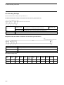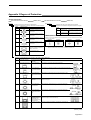
1
Microwave RFID System
V690 Series
User’s Manual
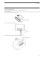
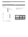
Read/Write Antenna, ID Tag, and Link Unit
Read/Write Antenna
Model V690-HMG01A
ID Tag
Model V690-D8KR01A
Link Unit
Model V690-L01
Cat. No. Z149-E1-02
Introduction
Thank you for choosing a V690-series Microwave-type RFID System. The V690 Series was developed by OMRON based on our
advanced technology and extensive experience. This user’s manual describes the functions, performance, and usage of the V690 Series.
When you use V690-series products, observe the following precautions:
• V690-series products must be operated by a qualified electrical engineer with expert knowledge on electrical systems.
• Read this user’s manual carefully, understand the V690-series products fully, and use them correctly.
• Keep this user’s manual in a safe place where it is easily accessible for future reference.
Application Considerations
When you use the V690 Series in the following environments, operate it within the ratings and functions, take sufficient safety measures, such as installing a fail-safe system, and consult your nearest OMRON representative.
(1) Use in conditions or environments not described in this manual
(2) Use for nuclear energy control, railroads, aeronautical systems, cars, combustion equipment, medical equipment, amusement
facilities, safety devices, etc.
(3) Use for applications that may have a serious influence on people’s lives and property or any other way requiring a high level
of safety.
Read and Understand this Manual
Please read and understand this manual before purchasing the product. Please consult your OMRON representative if
you have any questions or comments.
Warranty and Limitations of Liability
WARRANTY
OMRON's exclusive warranty is that the products are free from defects in materials and workmanship for a period of one
year (or other period if specified) from date of sale by OMRON.
OMRON MAKES NO WARRANTY OR REPRESENTATION, EXPRESS OR IMPLIED, REGARDING NONINFRINGEMENT, MERCHANTABILITY, OR FITNESS FOR PARTICULAR PURPOSE OF THE PRODUCTS. ANY
BUYER OR USER ACKNOWLEDGES THAT THE BUYER OR USER ALONE HAS DETERMINED THAT THE
PRODUCTS WILL SUITABLY MEET THE REQUIREMENTS OF THEIR INTENDED USE. OMRON DISCLAIMS ALL
OTHER WARRANTIES, EXPRESS OR IMPLIED.
LIMITATIONS OF LIABILITY
OMRON SHALL NOT BE RESPONSIBLE FOR SPECIAL, INDIRECT, OR CONSEQUENTIAL DAMAGES, LOSS OF
PROFITS OR COMMERCIAL LOSS IN ANY WAY CONNECTED WITH THE PRODUCTS, WHETHER SUCH CLAIM IS
BASED ON CONTRACT, WARRANTY, NEGLIGENCE, OR STRICT LIABILITY.
In no event shall the responsibility of OMRON for any act exceed the individual price of the product on which liability is
asserted.
IN NO EVENT SHALL OMRON BE RESPONSIBLE FOR WARRANTY, REPAIR, OR OTHER CLAIMS REGARDING THE
PRODUCTS UNLESS OMRON'S ANALYSIS CONFIRMS THAT THE PRODUCTS WERE PROPERLY HANDLED,
STORED, INSTALLED, AND MAINTAINED AND NOT SUBJECT TO CONTAMINATION, ABUSE, MISUSE, OR
INAPPROPRIATE MODIFICATION OR REPAIR.
Application Considerations
SUITABILITY FOR USE
OMRON shall not be responsible for conformity with any standards, codes, or regulations that apply to the combination of
products in the customer's application or use of the products.
At the customer's request, OMRON will provide applicable third party certification documents identifying ratings and
limitations of use that apply to the products. This information by itself is not sufficient for a complete determination of the
suitability of the products in combination with the end product, machine, system, or other application or use.
The following are some examples of applications for which particular attention must be given. This is not intended to be
an exhaustive list of all possible uses of the products, nor is it intended to imply that the uses listed may be suitable for the
products.
• Outdoor use, uses involving potential chemical contamination or electrical interference, or conditions or uses not
described in this manual.
• Nuclear energy control systems, combustion systems, railroad systems, aviation systems, medical equipment, amusement machines, vehicles, safety equipment, and installations subject to separate industry or government regulations.
• Systems, machines, and equipment that could present a risk to life or property.
Please know and observe all prohibitions of use applicable to the products.
NEVER USE THE PRODUCTS FOR AN APPLICATION INVOLVING SERIOUS RISK TO LIFE OR PROPERTY
WITHOUT ENSURING THAT THE SYSTEM AS A WHOLE HAS BEEN DESIGNED TO ADDRESS THE RISKS, AND
THAT THE OMRON PRODUCTS ARE PROPERLY RATED AND INSTALLED FOR THE INTENDED USE WITHIN THE
OVERALL EQUIPMENT OR SYSTEM.
Disclaimers
CHANGE IN SPECIFICATIONS
Product specifications and accessories may be changed at any time based on improvements and other reasons.
It is our practice to change model numbers when published ratings or features are changed, or when significant
construction changes are made. However, some specifications of the products may be changed without any notice. When
in doubt, special model numbers may be assigned to fix or establish key specifications for your application on your request.
Please consult with your OMRON representative at any time to confirm actual specifications of purchased products.
DIMENSIONS AND WEIGHTS
Dimensions and weights are nominal and are not to be used for manufacturing purposes, even when tolerances are
shown.
PERFORMANCE DATA
Performance data given in this manual is provided as a guide for the user in determining suitability and does not constitute
a warranty. It may represent the result of OMRON's test conditions, and the users must correlate it to actual application
requirements. Actual performance is subject to the OMRON Warranty and Limitations of Liability.
ERRORS AND OMISSIONS
The information in this manual has been carefully checked and is believed to be accurate; however, no responsibility is
assumed for clerical, typographical, or proofreading errors, or omissions.
Signal Words and Alert Symbols
• Meanings of Signal Words
For the safety operation of the V690-series RFID System, the signal word described below is used in this manual.
Precautions given with this signal word are important for safety operation. Be sure to follow the precautions provided.
The signal word and meaning are as follows:
WARNING
Indicates a potentially hazardous situation which, if not avoided, will result in minor
or moderate injury, or may result in serious injury or death. Additionally there may
be significant property damage.
• Meanings of Alert Symbols
• Indicates a danger of explosion under particular conditions.
Alert Statements in this Manual
WARNING
A lithium battery is contained in an ID Tag. Do not disassemble, deform under pressure, heat to
above 212 °F (100°C), or incinerate the ID Tag. Otherwise serious injury may result from fire or
rupturing of the battery.
Precautions for Safe Use
For safety, observe the following precautions.
1. Do not operate the product in any flammable, explosive, or corrosive gas environment.
2. Do not disassemble, repair, or alter the product.
3. Tighten the base lock screws and terminal block screws securely.
4. Use wiring crimp terminals of the specified size.
5. The 24 VDC power supply must meet the following conditions:
(1) The 24 VDC power supply must be used for the V690 Series only and must not be connected to any other devices or apparatuses.
(2) The voltage of the DC power supply must be within the specified ratings (24 VDC +10%/−15%).
6. Observe all precautions given in this manual.
Precautions for Correct Use
1. Do not install the V690-HMG01A, V690-D8KR01A, or V690-L01 in the following areas:
• Areas exposed to the direct sunlight.
• Humid areas where condensation may occur.
• Areas subject to vibration or shock.
2. Preliminary Check of Installation Site
The V690 Series uses the 2,450 MHz frequency band for communications between the Antenna and Tags. Some wireless equipment,
such as wireless LANs, cellular phones, personal handyphone systems and transceivers, motors, and switching power supplies, may
generate radio waves (noise) that affect communications with the Tags. If you must use the product near such devices, check for negative influences in advance.
To minimize the general influence of noise, follow these precautions:
• Ground any metallic material located around the product according to 100 Ω or less.
• Wire the product separated as far as possible from high voltages and heavy currents.
3. Ambient Environment and Communications Range
• The communications range depends on environment of the installation site. This is because metallic materials and the ground
reflect radio waves, and water and the human body absorb it. Place an Antenna and Tag in the communications range and check
the radio wave environment in advance.
• The V690-HMG01A Read/Write Antenna has a communications test command to check the radio wave environment at the working site. (Refer to 4-5 Communications Test.)
4. Ground any ground terminal to 100 Ω or less. Performance may deteriorate if the system is not properly grounded.
5. Cleaning the V690-HMG01A, V690-D8KR01A, and V690-L01
• Do not use any organic thinners. Resin materials and the case paint are dissolved by thinner.
Laws and Standards
1. Japan
The V690 is covered under the Specified Low-Power Wireless Station - Wireless Equipment for Mobile Object Identification
(ARIB RCR STD-29 Version 3.2) and thus does not require a license for use in Japan.
2. USA
The V690 is covered under FCC Part 15 Subpart C and thus does not require a license for use in the USA.
FCC ID: E4E6CYCIDV6900101
The following restrictions apply for use in the USA:
The output power must be set to the low-power (2 m) mode. This is the default setting.
If the Antenna is set to the high-power (5 m) mode, it will be in violation of FCC regulations and subject to punishment.
3. Europe
The V690 is covered under the Radio and Telecommunications Terminal Equipment Directive 1999/5/EC (R&TTE Directive).
Radio wave Directives:EN 300 440-1 (2001-09)
EN 300 761-1 (2001-06)
EMC Directives:
EN 300 440-1 (2001-09)
EN 300 761-1 (2001-06)
EN 301 489-1, -3 (2000-08)
A license is not required for use in the following countries.
Iceland, Ireland, England, Italy, Austria, the Netherlands, Greece, Switzerland, Spain, Denmark, Norway, Finland, France, Belgium, or Luxemburg.
The following restrictions apply for use in these countries:
Always use radio wave channel 5 for the Antenna. This is the default setting.
If the Antenna is set to any other radio wave channel, it will be in violation of the R&TTE Directive and subject to punishment.
4. Other Areas
Please ask your nearest OMRON representative.
Interference with Second-generation Low-power Data Communications Systems (Wireless LANs), Cellular Phones, etc.
1. Radio Interference between Wireless Stations
The 2,450 MHz frequency band (2,434.25 to 2,465.75 MHz) used by the V690 Microwave RFID System is designated for secondgeneration low-power data communications system (wireless LANs), local area wireless stations for mobile object identification, and
specified low-power wireless stations, as well as industrial, scientific, or medical equipment, such as microwave ovens. Radio interference can be expected in this frequency band.
Second-generation low-power data communications system (wireless LAN)
Low-power data communications systems
Amateur radio
Mobile object identification (microwave RFID)
Frequency band of
the V690
Specified
frequency
band
Note: Cellular phones and personal handyphone systems (900 to 1900 MHz) may also generate radio interference.
2. Possible Trouble Due to Radio Interference
• Communications Failure in RFID Systems
The radio waves from an ID Tag to the Antenna are weak and, therefore, communications between the Antenna and ID Tag may
fail due to radio interference caused by any other devices. Keep sufficient distance between the RFID System and any other
devices. For specific distances, refer to 8-5 Distance to Wireless LAN Cellular Phone (Reference).
• ID Tag Battery Power Loss
The electronic circuits in the ID Tag may be started by radio waves from other device, causing the battery power to be consumed
considerably. The V690 has a Tag power-saving function (refer to 4-7 ID Tag Power-Saving Functions) to control the battery
power. Nevertheless, the battery power may be still consumed depending on the working environment. Keep sufficient distance
between ID Tags and any other devices. For specific distances, refer to 8-5 Distance to Wireless LAN Cellular Phone (Reference).
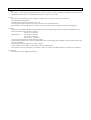
♦ Communications Failure in RFID System
♦ ID Tag Battery Power Loss
ID Tag
ID Tag
Antenna
Wireless LAN
Wireless LAN
3. Preparations at the Working Site
(1) Checks at the Working Site
1) Before using the V690, check that second-generation low-power data communications systems (wireless LANs), local area wireless stations (Microwave RFID Systems) for mobile object identification, or specified low-power wireless stations (Microwave
RFID Systems) are not operating near the V690.
2) If the V690 causes radio interference to a local area wireless station for mobile object identification, change the channel immediately or stop the V690 from emitting radio waves. Then, contact your nearest OMRON representative to take necessary actions to
prevent interference (e.g., partitioning).
3) Contact your nearest OMRON representative is the V690 causes radio interference to the second-generation low-power data communications system or specified low-power wireless station for mobile object identification or if any other trouble happens.
(2) Product Label and Caution Label
A product label and caution label come with the product.
• Attach the product label to a visible position on the Antenna unit.
• Attach the caution label to a visible position near the Antenna. The caution label must show the contact address or phone number
of the person in charge of installation and any other related information.
♦ Product Label
♦ Caution Label
The frequency 2450 MHz band of this device is designated for second-generation low-power data communication system (wireless LAN), local area radio
station (a license required) for mobile object identification and specified lowpower radio station (no license required) as well as industrial, scientific or
medical equipment such as microwave oven.
1) Before using this device, check that second-generation low-power data
communication system (wireless LAN), local area radio station (Microwave RFID System) for mobile object identification or specified low-power
radio station (Microwave RFID System) does not work near this device.
2) If this device causes radio interference to the local area radio station for
mobile object identification, change the frequency band immediately or
stop this device emitting the radio wave. Then, we would like you to contact below to take necessary actions to avoid interference (e.g., partitioning).
3) If this device causes radio interference to the second-generation lowpower data communication system or specified low-power radio station
for mobile object identification or if any other trouble happens, feel free to
contact below.
Contact:
(3) Meaning of Product Label
• 2.4:
Radio equipment that uses the 2.4 GHz frequency band
• RFID: The application of Radio Frequency Identification
• 10 mW: The Antenna power.
• @@@: Frequency band as follows:
The V690 Antenna uses the 2,450 MHz frequency band and, therefore “2450” is given.
Frequency band: 2440 2450 2455 MHz
2400 to 2427
Frequency band: 2,470.75 to 2,483.5 MHz
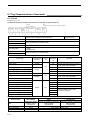
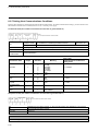
Manual Revision History
A manual revision history code is added to the end of catalog number shown at the lower right of the front cover
and back cover
Cat. No.
Z149-E1-02
Revision code
Revision
code
Date of revision
Reason for revision/Revised pages
01
October 2000
Original production
02
March 2004
Added sleep and standby time descriptions.
Added information on overseas standards and overhauled
the manual.
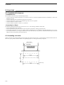
Contents
Contents
Chapter 1
Installation Precautions
1-1 Microwaves.........................................................................................................................1-1
1-1-1 V690 Frequency Bank: 2,450 MHz ............................................................................1-1
1-1-2 Characteristics of Microwaves....................................................................................1-2
1-1-3 Directional Characteristics of the Read/Write Head...................................................1-5
1-1-4 ID Tags as Radio Wave Reflectors.............................................................................1-6
1-2 Installation Procedure .........................................................................................................1-7
1-2-1 Installation Flowchart .................................................................................................1-7
1-2-2 Determining V690 Application Methods ...................................................................1-8
1-2-3 Programming the Host ..............................................................................................1-11
1-2-4 Installation to the System..........................................................................................1-12
1-2-5 Confirming Communications with Tags...................................................................1-12
1-3 International Radio Wave Laws........................................................................................1-14
Chapter 2
Features and System Configuration
2-1 Features ...............................................................................................................................2-1
2-2 System Configuration .........................................................................................................2-2
2-3 Operation Overview............................................................................................................2-4
Chapter 3
Specifications and Performance
3-1 H690-HMG01A Read/Write Antenna ................................................................................3-1
3-1-1 Specifications..............................................................................................................3-1
3-1-2 Dimensions .................................................................................................................3-1
3-1-3 Connector Signals (Connector Enclosed) ...................................................................3-2
3-1-4 Indicators ....................................................................................................................3-2
3-2 V690-D8KR01A ID Tag.....................................................................................................3-3
3-2-1 Specifications..............................................................................................................3-3
3-2-2 Dimensions .................................................................................................................3-3
3-2-3 Memory Map ..............................................................................................................3-4
3-2-4 Battery Life Characteristics ........................................................................................3-5
3-2-5 Battery Voltage Alarm Function.................................................................................3-5
3-3 V690-L01 RS-422A/485 Link Unit ....................................................................................3-6
3-3-1 Specifications..............................................................................................................3-6
3-3-2 Dimensions .................................................................................................................3-6
3-3-3 Function ......................................................................................................................3-7
3-4 Connecting Cables ..............................................................................................................3-8
3-4-1 Specifications..............................................................................................................3-8
3-4-2 Dimensions .................................................................................................................3-8
3-5 Tag Communications Performance...................................................................................3-10
3-6 Host Communications Specifications ...............................................................................3-11
Contents-11
Contents
Chapter 4
4-1
4-2
4-3
4-4
4-5
4-6
4-7
Functions
Single, FIFO, and Multi Mode Access ............................................................................... 4-1
Switching between Low-power (2 m) and High-power (5 m) Mode .................................4-2
Radio Wave Channel Switching .........................................................................................4-3
Simplified Communications Test .......................................................................................4-4
Communications Test .........................................................................................................4-5
Write Protect Function........................................................................................................4-6
ID Tag Power-Saving Functions.........................................................................................4-8
Chapter 5
Installation and Connection
5-1 Read/Write Antenna and ID Tag ........................................................................................5-1
5-1-1 Installation Environment ............................................................................................5-1
5-1-2 Installing the Antenna.................................................................................................5-2
5-1-3 Rainproofing the Antenna...........................................................................................5-3
5-1-4 Install Tags..................................................................................................................5-4
5-1-5 Connecting the Cable to the Antenna .........................................................................5-5
5-2 Wiring the Host...................................................................................................................5-6
5-2-1 Wiring an RS-232C Interface .....................................................................................5-6
5-2-2 Wiring for RS-422A/485 ............................................................................................5-9
5-3 Link Unit...........................................................................................................................5-14
5-3-1 Installation Environment ..........................................................................................5-14
5-3-2 Installing Link Units .................................................................................................5-14
5-3-3 Wiring Link Units.....................................................................................................5-15
5-3-4 Switch Settings .........................................................................................................5-18
Chapter 6
Controlling Operation from the Host
6-1 Operation Status of Read/Write Antenna and ID Tags.......................................................6-1
6-2 Communications Operation Sequences .............................................................................. 6-2
6-2-1 Communications Modes with Commands..................................................................6-2
6-2-2 Communications Modes with Communications Designations...................................6-5
6-2-3 Other Communications Modes ...................................................................................6-7
6-3 Command and Response Formats.......................................................................................6-8
6-4 Commands and Communications Designations ...............................................................6-10
6-5 Data Code Designation .....................................................................................................6-13
6-6 Communications Response Flow......................................................................................6-15
6-7 Tag Communications Commands.....................................................................................6-16
6-7-1 Read ..........................................................................................................................6-16
6-7-2 ID Code Read ...........................................................................................................6-18
6-7-3 Designated Tag Read ................................................................................................6-20
6-7-4 Write .........................................................................................................................6-22
6-7-5 Designated Tag Write ...............................................................................................6-24
6-7-6 Data Fill ....................................................................................................................6-26
6-7-7 Designated Tag Data Fill ..........................................................................................6-28
Contents-12
Contents
6-7-8 Communications Test ...............................................................................................6-29
6-8 Antenna Operation Commands.........................................................................................6-30
6-8-1 Auto Repeat Cancel ..................................................................................................6-30
6-8-2 Reset..........................................................................................................................6-31
6-8-3 Request to Respond ..................................................................................................6-32
6-8-4 Request to Retransmit ...............................................................................................6-33
6-9 Antenna Setting Commands .............................................................................................6-34
6-9-1 Radio Wave Transmission ON/OFF.........................................................................6-34
6-9-2 Communications Range and Radio Wave Channel Selection ..................................6-35
6-9-3 Radio Wave Output Status Read ..............................................................................6-36
6-9-4 Setting the Time to Wait for a Tag ...........................................................................6-37
6-9-5 Setting the Command Data Response Time .............................................................6-38
6-9-6 Read Data Length Setting .........................................................................................6-39
6-9-7 Setting Host Communications Conditions................................................................6-40
6-9-8 Setting the Station Number.......................................................................................6-41
6-9-9 Reading Settings .......................................................................................................6-42
6-10 End Code List .................................................................................................................6-43
Chapter 7
7-1
7-2
7-3
7-4
7-5
7-6
Trial Operation....................................................................................................................7-1
Diagnosis Function .............................................................................................................7-2
Error List .............................................................................................................................7-3
Errors and Countermeasures ...............................................................................................7-4
Maintenance and Inspection ...............................................................................................7-5
Troubleshooting ..................................................................................................................7-6
Chapter 8
8-1
8-2
8-3
8-4
8-5
8-6
8-7
Startup and Operating Procedures
Communications Performance and Characteristic Data (Reference)
Communications Area (Reference).....................................................................................8-1
Influence of Ambient Temperature (Reference).................................................................8-2
Communications Time (Reference)....................................................................................8-3
Mutual Interference between Antennas (Reference) ..........................................................8-5
Distance to Wireless LAN Cellular Phone (Reference) .....................................................8-6
Influence of Tag Installation Angle (Reference) ................................................................8-7
Influence of Back Metal (Reference)..................................................................................8-8
Appendix
Appendix 1 Glossary...................................................................................................... Appendix-1
Appendix 2 JIS 8-bit Code List (ASCII List) ................................................................ Appendix-4
Appendix 3 Degree of Protection................................................................................... Appendix-5
Appendix 4 Standard Models......................................................................................... Appendix-6
Contents-13
Chapter 1 Installation Precautions
1-1 Microwaves
The V690-series Microwave RFID (radio frequency identification) System has a communications range between the Antenna and a Tag
of up to 5 m. A Microwave RFID System, however, employs radio waves, and installation must be performed with care to ensure proper
performance.
1-1-1 V690 Frequency Bank: 2,450 MHz
The frequency band of 2,450 MHz that is generally approved under law for use in microwave RFID systems is the same frequency band
as used by microwave ovens. Under the law, microwaves are from 3,000 to 30,000 MHz and 2,450 is a submicrowave. Microwaves are
transmitted by metal and in some application environments can be propagated for long distances. It is thus very import when setting up
an application to use the Communications Test command and confirm the effects of the V690 Antenna and other wireless devices in the
working site. (Section 4-5).
Frequencies and Wavelengths
RFID system
Frequency
Electromagnetic induction
Microwave
propagation
OMRON products
Wavelengths (m)
125 kHz
V700
2,400
530 kHz
V600
566
13.56 MHz
V670, V720
22
2.45 GHz
V690
0.12
Wireless Devices that Operate in the 2.4 GHz Frequency Band:
RFID Systems
Wireless LANs: IEEE 802.11b, IEEE 802.11g
Bluetooth
Other original wireless devices
1-1
1-1 Microwaves
1-1-2 Characteristics of Microwaves
♦ Influence of External Objects
• Radio Wave Absorbers: Water, Human Body, Water Films, Water-absorbing Materials, etc.
Radio waves (microwaves) penetrates any solid body or liquid other than metal, but it is attenuated while penetrating. In particular,
water absorbs radio waves extremely well. When radio waves penetrate water, the radio waves are absorbed considerably. Also, radio
waves are attenuated remarkably in a human body, which contains much water. There must thus be no solid body or liquid between the
Antenna and a Tag.
A general-purpose plastic or glass plate that is a few millimeters thick does not absorb radio waves, and radio wave attenuation is not a
serious problem with these materials. However, the radio wave attenuation depends on a type of material and/or thickness of external
objects which the radio wave penetrates. Perform a communications test in the working site in advance. If, however, the communication
is performed through a plastic plate or glass plate that is wet or covered with water due to rain, the radio waves will be absorbed. The
radio waves will be attenuated by the water film and the communication may fail. Perform a communications test in the working site in
advance and take great care not to get out of the communications range during operation.
Dry wood and paper do not attenuate radio waves very much. Wood and paper, however, absorb water easily. Wet wood and paper may
attenuate radio waves considerably. Perform a communications test in the working site in advance using both dry materials and wet
ones.
A part of the radio
waves is reflected.
Radio waves transmitted
from an Antenna
Object
Absorbed in an object and attenuated.
Tag
Radio waves transmitted from a Tag.
• Radio Wave Reflectors: Metal, Ground, Etc.
Metal reflects radio waves (microwaves) like a mirror reflects light. If there is a metal surface near an Antenna communications area,
the communications area will be affected by the metal. If a metal object is placed between an Antenna and Tag, communications
between the Antenna and Tag may fail. Metal, whether a metal plate or wire netting, may affect communications. Also, the ground
affects the communications like metal.
As shown below, a radio wave absorber or reflector can be used to interrupt radio waves. When you interrupt radio waves, perform a
communications test in the working site in advance.
Example of radio wave absorber: ECCOSORB AN75 (61 x 61 cm, E&C Engineering)
Incoming
Communications area
Outgoing
Radio wave interruption
Antenna
Tag for which you
want to process data
Tag for which you do not want to process data
1-2
1-1 Microwaves
• Communications Area Affected by the Ground
If an Antenna is installed near the ground, radio waves (microwaves) emitted from the Antenna and ones reflected by the ground overlap
each other. Therefore, the outline of the communications area becomes ragged and complex. In this case, dead zones may be formed frequently, where no communications can be made to a Tag.
Antenna
Tag
Ground
Communications area affected by the ground
Tag
Communications area not
affected by the ground
Antenna
Ground
Precaution for Correct Use
Depending on the working site, a special point may be created in the communications area preventing communications
with the Tag at that point. Be sure to check communications with a communications test (refer to Section 4-5).
1-3
1-1 Microwaves
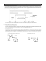
♦ Metal Propagation of Microwaves
Microwaves will resonate in any metal that is an integral multiple of the wavelength of microwaves (122 mm) in length, causing the
metal to act as an antenna. This “antenna” will cause the microwaves to be propagated in the metal a long way with little attenuation.
Metal
Ground
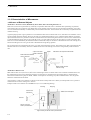
A V690 Antenna installed in a high location can affect Antennas installed far away when it transmits radio waves. If the is metal that
will function as an antenna, the metal will cause the radio waves to be propagated a long way with little attenuation. In one actual example, a Read/Write Antenna installed more than 30 m away was affected.
Antenna
ID Tag
More than 30 m
1-4
Antenna
Antenna
ID Tag
ID Tag
1-1 Microwaves
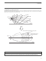
1-1-3 Directional Characteristics of the Read/Write Head
Cellular phones, wireless LANs, other common wireless devices must be able to communicate with other wireless devices within a specific area. They thus use nondirectional antennas and transmit radio waves in all directions.
2,400 to 2,497 MHz
Output: 260 mW
800 MHz or 1.5 GHz band
Output: 800 mW
Wireless LAN
Cellular phone
Microwave RFID antennas, however, must communicate only with specific ID Tags. The Read/Write Antenna thus use directional radio
waves to detect specific ID Tags. When the V690 Read/Write Antenna is set in low-power (2 m) mode, the oscillation power inside the
Antenna is amplified to 4 mW, the directional antenna’s gain goes to 14 dBi, and 100 mW is radiated. The radiation level from the back
of the case is 1 mW maximum, a negligible level.
V690 Antenna
Radiation level from back of case: 1 mW max.
Radiation level in center of case: 100 mW
1-5
1-1 Microwaves
1-1-4 ID Tags as Radio Wave Reflectors
Regardless of whether a microwave system or a electromagnetic induction system is used, the ID Tags in common RFID systems are
transponders. The ID Tags do not transmit radio waves themselves, but rather they transmit data by reflecting the radio waves from the
Read/Write Antenna. The Read/Write Antenna can communicate with ID Tags in the communications area because the ID Tags act as
reflectors. Also, the battery built into an ID Tag is not used to transmit radio waves, but only for the operation of the electronic circuits
inside the Tag (e.g., static-RAM memory and the CPU). The battery in an ID Tag thus has a long life of 5 years (reference value).
The operation of an ID Tag as a reflector also makes them very sensitive. When the V690 Antenna and ID Tag are separated by only
1 m, the ID Tag returns only one part in one hundred million of the radio wave level output by the Antenna. If the V690 is set to the lowpower (2 m) mode, the power of the radio waves received by the Antenna at a distance of 1 m is only 1 nW. The V690 uses subcarrier
technology to perform modulation at frequencies lower than 2,450 MHz and create a structure resistant to noise from other wireless
devices in the 2.4 GHz band, but it is still more susceptible to noise in the 2.4 GHz band than common wireless devices.
Patch antenna (reflector)
V690 Antenna
Patch antenna
2.45 GHz
oscillator
4 mW
Demodulation
circuit
20dBm
=100mW
-20dBm
=10 µW
(1/10,000)
Demodulation
circuit
−60dBm=1nW
(1/100,000,000)
Distance: 1 m
1-6
ID Tag
1-2 Installation Procedure
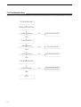
1-2 Installation Procedure
1-2-1 Installation Flowchart
The following flowchart shows the procedure to introduce a V690 System.
START
Determine V690 application methods (Section 1-2-2)
1. Stationary or moving communications
2. Output power mode
3. Distance between Antenna and Tags
4. Communications time for moving Tags
5. Communications with host
6. Introducing other wireless devices
Program the host (Section 1-2-3)
Install the system (Section 1-2-4)
Test communications (Section 1-2-5)
Trial operation of entire system
Operate system
END
Refer to the following sections for further information:
1-2-2 Determining V690 Application Methods
1-2-3 Programming the Host
1-2-4 Installation to the System
1-2-5 Confirming Communications with Tags
1-7
1-2 Installation Procedure
1-2-2 Determining V690 Application Methods
Consider the information provided in this section when determining the applications methods of the V690.
(1) Communications with Stationary or Moving Tags
ID Tags are attached to product, palettes, or other object and then communications are performed with the Read/Write Antenna. It makes
an important difference whether communications are performed with ID Tags when they are stationary or when they are moving. Decide
which is the best method after proper consideration.
---
Communications with stationary ID Tags
Communications with moving ID Tags
Objects are detected with
sensors and then the host
sends a command to the
Antenna.
Objects are detected with
sensors and then the host
sends a command to the
Antenna.
Communications
reliability
Acceptable
If communications fail due to
noise, retries can be performed to increase reliability.
There may be, however,
areas in which communications are not possible or distorted due to the effects of
reflections or other factors.
Acceptable
If communications fail due to noise, retries may not be possible
if the Tag has left the communications area, possibly affecting
the entire system. Some means of recovery must be used
when communications fail.
Even if there are areas in which communications are not possible due to the effects of reflections or other factors, the movement of the Tags through the communications area will enable
communications.
System cost
Acceptable
Sensors are required detect
objects, increasing the system cost by the cost of the
sensors.
Acceptable
Sensors are required detect
objects, increasing the system cost by the cost of the
sensors.
Effect on other V690
Antennas or other
wireless devices
Good
The effects will be relatively small because the Antenna will
transmit radio waves only when communicating. The effects,
however, will have to be checked in the working site.
Note 1: Command types: Trigger, Auto, and Repeat
(Refer to 6-2-1.)
Note 2: See the illustration at the right for one means
of detecting objects.
Note 3: As one example of a means to recover when
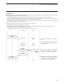
communications fail, two Antennas can be
used. If communications with the first Antenna
fail, they can be performed from the second
Antenna, as shown in the following illustration.
Antenna 1
Antenna 2
ID Tag
1-8
Objects are not detected and
Auto or Repeat command is
used.
Good
Sensors are not required to
detect objects.
NG
The system will be affected
greatly because radio waves
are being transmitted constantly.
Host
Sensor
V690 Antenna
ID Tag
1-2 Installation Procedure
(2) Selecting the Output Power Mode
The “5 m” given for the high-power output power mode is the maximum communications range. The distance between the Read/Write
Antenna and ID Tag must be, under normal circumstances, less than 5 m. Using the high-power mode increases the output power,
increasing the radio waves reflected from the surroundings, which can in turn reduce the communications distance or even enable communications in unlikely locations. The low-power (2 m) mode should be used whenever possible to reduce affecting other devices. The
low-power (2 m) mode is the default setting.
Output power mode
Low-power (2 m) mode
High-power (5 m) mode
Radio wave output from
Antenna
4 mW
10 mW
Distance between Antenna
and Tag at room temperature
2 m max.
3.5 m max.
Installation distance between
two V690 Antennas installed
in parallel
4.5 m min. (See note.)
6 m min. (See note.)
Note:
The parallel installation distances of 4.5 and 6 m minimum given above assume that there is no radio wave reflection. Any
metal in the surrounding area will affect the installation distance. It may be necessary to program the system so that adjacent
Antennas do not transmit at the same time or so that they use different radio wave channels.
(3) Distance between Read/Write Antenna and ID Tags
The communications distance can be calculated as shown below when there is no metal near the Read/Write Head or ID Tag.
Conditions:
Low-power (2 m) mode
Tag installation angle: ±15° = −15% max.
Metal behind Tag at 0 mm: −10% (from Section 8-7)
The distance will be set to 70% of the maximum communications distance.
Calculation:
2.0 m × (1 − 0.15) × (1 − 0.10) × 70% = 1.0 (m)
The width of the communications for each Antenna can be affected by metal at the working site. Always perform communications tests
to measure the radio wave environment value and check for radio wave interference at the working site.
(4) Time for Communications with Moving Tags
A calculation example for the speed of Tag movement is provided in
Section 8-3. Here, the time available for communications will be calculated.
Conditions:
Low-power (2 m) mode
Distance between Tag and Antenna: 1.5 m
Width of communications area at 20°C: 800 mm (from Section 8-1)
Tag speed: 100 mm/s
Tag rotation: 0° to 360°
Tag installation angle: ±15° = −15% max.
Metal behind Tag at 5 mm: −5% (from Section 8-7)
V690 Antenna
Width of
communications area
Distance
ID Tag
Calculation:
800 ÷ 100 × (1-0.15) × (1-0.05) = 6.5 s
The system would be designed to complete communications well within 6.5 s to allow for a margin for error. The communications time
required to read 8 Kbytes is 260 ms (from Section 8-3), which provides plenty of margin.
1-9
1-2 Installation Procedure
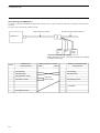
(5) Communications between Read/Write Antenna and Host
With the V690 Series, either RS-232C or RS-422A/RS-485 can be used for communications between the Read/Write Antenna and the
host. Select the type of communications based on the required baud rate and length of the communications path.
Protocol
RS-232C
RS-422A/RS-485
Baud rate
19.2 kbps max.
115.2 kbps max.
Path length
15 m max.
300 m max.
Note 1: Whenever possible, use the BCC as a check code for communications between the Read/Write Antenna and the host, particularly if the baud rate is above 20 kbps.
Note 2: Specify the data length to use when returning data from the Read/Write Antenna to the host. Refer to Section 6-9-6. Keep the
data length as short as possible to help improve the reliability of data communications.
(6) Introducing Other Wireless Devices
It is not recommended to use wireless LANs or other wireless devices that operate in the 2.4 GHz band in the same building as the
V690. OMRON cannot assume responsibility for such applications. If such applications are unavoidable, observe the following precautions.
Do Not Use FHSS Wireless Devices
Do not use FHSS (frequency hopping spread spectrum) systems or Bluetooth systems. Use DSSS (direct sequence spread spectrum)
systems (wireless LAN IEEE 802.11b) or other frequency bands (e.g., the 400 MHz band).
Post Warnings
Post warnings asking for caution in using wireless devices, such as wireless LAN or Bluetooth systems, because an RFID system using
the 2.4 GHz band is being operated.
1-10
1-2 Installation Procedure
1-2-3 Programming the Host
Observe the following precautions when programming the host (e.g., Programmable Controller or personal computer).
Retries
Perform retries by sending the same command after a delay of 10 ms whenever the end code in the response from the Read/Write
Antenna is 72 (no Tag) or 70 (communications error with Tag).
Executing Multiple Commands
For example, when executing a read followed by a write, wait at least 200 ms after receiving a normal response (00) for the read command before executing the Write command. The ID Tag will sleep for at least 200 ms.
Writes with Verification
To increase the reliability of writing, use Write commands with verification (W1, W4, or W7) whenever possible.
End Code 7B
An end code of 7B is a warning indicating that the voltage of the battery in the ID Tag has dropped. Record the ID code of the ID Tag for
which an end code of 7B was returned and have the battery replaced. If the ambient temperature is 0°C or lower, an end code of 7B may
be returned even if the battery has sufficient charge. End codes of 7B can generally be ignored if the temperature is 0°C or lower.
Communications Log
Keep a log of commands and responses between the Read/Write Antenna and ID Tags to help in troubleshooting any problems that
might occur. At the very least, keep a log of end codes and ID codes.
Discontinuing Auto Repeat Commands
When communications have been completed for Auto Repeat Commands, be sure to send the Auto Repeat Clear command (C2) to stop
transmission of radio waves. This is necessary to reduce the time that radio waves are transmitted and thus reduce the effects on other
Antennas.
Number of Read/Write Bytes
Communications between the Read/Write Antenna and an ID Tag are performed in units of 256-byte packets. Even if the required number of read bytes is only 2 kbytes, program structure, such as the use of common program sections, may call for 8-kbyte reads. Whenever possible, however, read/write only the required number of bytes to increase the stability of communications.
Errors in Host Communications
Read commands are sent to the Read/Write Antenna, which returns a response. If an error occurs in host communications, it is not
always necessary to send the same command again. The Request to Retransmit command (H1) can be sent to read the response again.
End Code 70 for Writes
If an end code of 70 is returned for a Write command, it is possible that the specified write address in the ID Tag was corrupted and that
the data was written to the wrong address. Take steps in programming to handle this possibility.
1-11
1-2 Installation Procedure
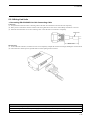
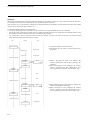
1-2-4 Installation to the System
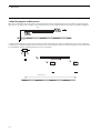
Observe the following precautions when installing the Read/Write Antenna.
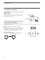
Installation Direction
Install the Antennas in a consistent direction to enable easier maintenance.
Operation Indicators
The operation of the Antenna can be monitored using the four indicators
provided on it. This will aid in maintenance work. Install the Antenna so
that the indicators are easily visible.
V690 Antenna
ID Tag
Indicators
1-2-5 Confirming Communications with Tags
Object
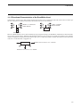
♦ Confirmation for Overall System
The width of the communications for each Antenna can be affected by
metal at the working site. Always perform communications tests to measure the radio wave environment value and check for radio wave
interference at the working site.
Evaluating Communications Performance for Individual V690
Antennas
With the line stopped, use the Communications Test command (T0) and
the commands that will actually be used to confirm the range in which
communications are possible for each V690 Antenna. Set up the system
so that the radio wave environment value is 50 or less.
Influence from Other V690 Antennas
Set any V690 Antennas that might influence operation so that they are
transmitting radio waves and then repeat the above evaluation.
V690 Antenna
Vertical margin
ID Tag
Radio wave transmission
V690
Antenna
1-12
V690
Antenna
Communications width
1-2 Installation Procedure
♦ Countermeasures for High Radio Wave Environment Values
Perform tests using the Communications Test command and maintain a radio wave environment value of 50 or less. Stable operation
will not be possible if the radio wave environment value is greater than 50. If the value cannot be reduced below 50, take the following
measures.
High Radio Wave Environment Values for Individual V690 Antennas
• Adjust the distance between the Read/Write Antenna and ID Tags or adjust positioning.
• Remove as many metallic objects as possible to reduce the effects of metal.
High Radio Wave Environment Values Due to Other V690 Antennas
• Do not transmit radio waves from adjacent Antennas at the same time.
• Set the radio wave channels to 0, 5, and 9.
The V690 supports 10 channels of radio wave frequencies from channel 0 to channel 9. These can be used to reduce interference with
other wireless devices. For adjacent V690 Antennas, however, only three channels can be used, i.e., 0, 5, and 9 (default: 5). This is
because of the high-speed communications (600 kbps) of the V690, which requires that the channels of adjacent Antennas be separated
by at least 4 channels.
Channel
Frequency
(MHz)
Note:
0
1
2
3
4
5
6
7
8
9
2437.5
2440.0
2442.5
2445.0
2447.5
2450.0
2452.5
2455.0
2457.5
2460.0
Only channel 5 can be used in Europe. It is thus not possible to use different channels to prevent interference, so adjust the timing of transmitting radio waves instead.
♦ Testing Communications with Tags
Test Mechanism
V690
One packet (256 bytes) is sent from the Read/Write Antenna to the ID
256 bytes
Antenna
Tag. The ID Tag returns 256 bytes to the Antenna to complete the first
cycle. In the communications test, this cycle is repeated 256 times,
meaning that approximately 65 Kbytes of data is handled during one
256 bytes
communications test. Approximately 2.5 s is required to complete the
test.
The Read/Write Antenna uses a CRC (cyclic redundancy check) code to
256 times
check the data and determines if each cycle is OK or NG. The NG count
is returned as the radio wave environment value. The radio wave environment value is between 0 and 256.
ID Tag
Application Method
Radio Wave Environment Values (Example)
Send the Communications Test command (T0) from the host to the Read/
--Radio wave environment value
Write Antenna. Refer to Section 6-7-8 for the command and response for1
10
mats. The radio wave environment value may vary depending on the tim2
3
ing. Repeat the test at least five times for each position of the Read/Write
3
5
Antenna and ID Tag and use the average value.
4
50
5
Average
12
16
1-13
1-3 International Radio Wave Laws
1-3 International Radio Wave Laws
Laws governing the use of radio waves are different in different countries. The output power modes and radio wave channels that can be
used thus depend on the country where the Microwave RFID System is used.
♦ Japan
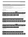
The V690 falls under the frequency band from 2,434.5 to 2465.75 MHz stipulated in the Specified Low-Power Wireless Station - Wireless Equipment for Mobile Object Identification (RCR STD-29). Each Antenna is issued a Technical Regulation Conformity Certification by the Telecom Engineering Center (http://www.telec.or.jp/) before shipping. Within Japan, either the low-power (2 m) or highpower (5 m) mode can be used and any of the radio wave channels from channel 0 to channel 9 can be used.
Radio wave
channel (MHz)
Output power Low (2 m)
mode
High (5 m)
0
1
2
3
4
5
6
7
8
9
(2437.5) (2440.0) (2442.5) (2445.0) (2447.5) (2450.0) (2452.5) (2455.0) (2457.5) (2460.0)
OK
OK
OK
OK
OK
OK
OK
OK
OK
OK
OK
OK
OK
OK
OK
OK
OK
OK
OK
OK
♦ USA
The V690 conforms to FCC 15.245 of the FCC (http://www.fcc.gov/). In FCC 15.245, however, 500 mV/m is specified as the fundamental wave electric field strength. The high-power (5 m) mode thus cannot be used. Within the USA, only the low-power (2 m) mode
can be used, but any of the radio wave channels from channel 0 to channel 9 can be used.
(If the Antenna is set to the high-power (5 m) mode, it will be in violation of FCC regulations and subject to punishment.)
Radio wave
channel (MHz)
Output power Low (2 m)
mode
High (5 m)
0
1
2
3
4
5
6
7
8
9
(2437.5) (2440.0) (2442.5) (2445.0) (2447.5) (2450.0) (2452.5) (2455.0) (2457.5) (2460.0)
OK
OK
OK
OK
OK
OK
OK
OK
OK
OK
No
No
No
No
No
No
No
No
No
No
♦ Europe
In the EU, an application must be made according to the Radio and Telecommunications Terminal Equipment Directive 1999/5/EC
(R&TTE Directive). The V690-HMG01A complies with Radio Wave Directives EN 300 440-1and EN 300 761-1, EMC Directives
EN 301 489-1, -3, and Safety Directive EN 61010-1.
At present, laws regarding radio waves vary with the country, although the laws are scheduled to be revised to respect the ERC Recommendation 70-03 E for short-distance wireless devices (including RFID systems). The V690 conforms to specification in Annex 11: RF
Identification Systems in this Recommendation, but the frequency range is limited to 2,446 to 2,454 MHz. The V690 can thus be used
only when set to radio wave channel 5. Within the EU, only radio wave channel 5 can be used, but either the low-power (2 m) or highpower (5 m) mode can be used.
(If the Antenna is set to any radio wave channel other than channel 5, it will be in violation of the R&TTE Directive and subject to punishment.)
Radio wave
channel (MHz)
Output power Low (2 m)
mode
High (5 m)
Note:
1-14
0
1
2
3
4
5
6
7
8
9
(2437.5) (2440.0) (2442.5) (2445.0) (2447.5) (2450.0) (2452.5) (2455.0) (2457.5) (2460.0)
No
No
No
No
No
OK
No
No
No
No
No
No
No
No
No
OK
No
No
No
No
Refer to Laws and Standards at the front of this manual for a list of countries where the V690 can be used.
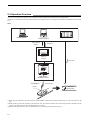
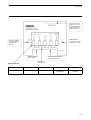
Chapter 2 Features and System Configuration
2-1 Features
The V690 Series is a Microwave RFID System that achieves long-range, high-performance communications. The V690 System is
highly suited for assembly lines, physical distribution systems, and product control applications.
V690-HMG01A
Read/Write Antenna
V690-D8KR01A
ID Tag
V690-L01
RS-422A/485 Link Unit
(1) V690-HMG01A Read/Write Antenna
• Consists of an antenna unit, which communicates with ID Tags, and a controller unit, which controls communications.
• The antenna unit achieves a communications speed of 600 kbps and a maximum communications range of 5 m.
• The Antenna uses circularly polarized waves as radio waves. An ID Tag facing the Antenna can communicate at any angle of
rotation on the center axis. The maximum communications range depends on the angle of the Tags.
• This Antenna is a specified low-power wireless station and, therefore, no wireless station license is required for use in Japan.
• A Multi Access function enables accessing several Tags in the Antenna communications area and a FIFO (First-In First-Out)
function enables accessing Tags coming in the communications area sequentially one by one.
• Commands from the host can be used to switch the output power mode (communications range) between the low-power (2 m) and
high-power (5 m) mode, or to switch the radio wave channel at the working site. You can select the most suitable output power
mode at the working site to easily prevent mutual interference between Antennas.
• The controller unit supports an RS-232C interface. It can connect to a general-purpose personal computer or Programmable Controller (PLC) that supports RS-232C communications. Also, several Antennas can be connected to one host using the RS-422A/
485 Link Unit.
• A simplified communications test function, which can check communications with Tag without a host, and a communications
test, which can check the radio wave environment at the working site, are also supported.
(2) V690-D8KR01A ID Tag
• This Tag contains a battery and have a memory capacity of 8 kbytes.
• Write Protection is supported to disable writing in using of 256 bytes.
• An IEC IP67 (JEM IP67g) protective structure has been achieved. This Tag can be used even in a place subject to water and oil
splashes.
• The battery life is 5 years at 25°C (reference value). The battery is not replaceable, but a power-saving function and battery voltage alarm function are supported.
(3) V690-L01 RS-422A/485 Link Unit
• Use when communicating with the host through RS-422A or RS-485 communications.
• The power supply to the Read/Write Antenna can be controlled, the operation/setting mode can be switched, communications can
be switched between RS-422A and RS-485, and the terminating resistance can be turned ON/OFF.
2-1
2-2 System Configuration
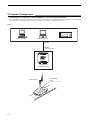
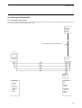
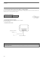
• Example System Configuration for the V690-HMG01A: 1:1 Host Connection via RS-232C
The V690-HMG01A supports an RS-232C serial interface and can connect to a general-purpose personal computer or Programmable
Controller easily. All communications with Tags are controlled according to commands from the host.
Host
Desktop computer
Programmable Controller
Notebook computer
RS-232C
V690-A4@
Connecting Cable
V690-HMG01A
Read/Write Antenna
Communication
2-2
V690-D8KR01A
ID Tag
2-2 System Configuration
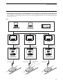
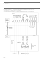
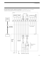
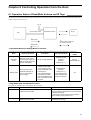
• Example System Configuration for the V690-HMG01A: 1:N Host Connection via RS-422A (4-wire)/RS-485 (2-wire)
The V690-HMG01A supports an RS-422A/485 interface and up to 32 V690-HMG01A Antennas can connect to one general-purpose
personal computer or Programmable Controller through up to 32 V690-L01 RS-422A/485 Link Units. The maximum length of RS422A/485 cable is 300 m.
Host
Desktop computer
Notebook computer
Programmable Controller
RS-422A/RS-485
V690-L01
Link Unit
Communication
V690-A5@
Connecting Cable
V690-A5@
Connecting Cable
V690-A5@
Connecting Cable
V690-HMG01A
Read/Write Antenna
V690-L01
Link Unit
V690-L01
Link Unit
V690-HMG01A
Read/Write Antenna
Communication
V690-D8KR01A
ID Tag
V690-HMG01A
Read/Write Antenna
Communication
2-3
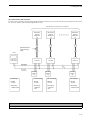
2-3 Operation Overview
An overview of V690 Series operation is provided below using assignments of destination in car transportation.
An ID Tag is mounted on the car body and the destination is assigned to the car according to the destination information stored in the ID
Tag.
Host
Desktop computer
Notebook computer
Auto command
(Read)
Programmable Controller
Response
V690-L01
Link Unit
I/O Control
V690-HMG01A
Read/Write Antenna
V690-D8KR01A
ID Tag
Communication
Execution
(Assignment)
(1)When an auto command is sent from the host to the Read/Write Antenna, the Antenna becomes ready to work and waits for an ID
Tag.
(2)When an ID Tag enters the Antenna’s communications area, the Antenna reads data from the ID Tag and returns the data from the
memory area specified in the auto command (Read) as a response.
(3)Based on the data, the host controls a transportation device and assigns the destination for the car.
2-4
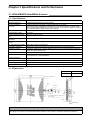
Chapter 3 Specifications and Performance
3-1 H690-HMG01A Read/Write Antenna
3-1-1 Specifications
Item
Specifications
Emitting frequency
2,450 MHz band (2,434.25 to 2,465.75 MHz)
Power supplied to
Antenna
5 mW in low-power (2 m) mode, 10 mW in high-power (5 m) mode
(The system is thus classified as a specified low-power wireless station - wireless equipment for mobile object identification in Japan. The user is not required to apply for a license
for a wireless station in Japan for this type of system.)
Power supply
24 VDC +10%/−15%
Consumption current
0.5 A max.
Ambient operating temperature
-20 to 60°C (with no icing)
Ambient operating
humidity
35% to 85% (with no condensation)
Ambient storage temperature
-20 to +60°C (with no icing)
Ambient storage humidity
35% to 85% (with no condensation)
Insulation resistance
20 MΩ min. (at 100 VDC) between the cable terminals as a group and the case
Withstand voltage
1,000 VAC, 50/60 Hz for 1 minute, detected current of 1 mA or less between the cable terminals as a group and the case
Degree of protection
IP62 (IEC60529) *With the cable outlet turned downward.
Vibration resistance
10 to 150 Hz, single amplitude 0.35 mm, maximum acceleration 50 m/s2 sweeping 10 times
for 8 minutes in X, Y, and Z directions
Shock resistance
150 m/s2 three times each in X, Y, and Z directions, i.e., 18 times total
Indicator
Power supply, radio wave emission, host transmission, Tag transmission
Cable length
0.5 m (A round connector (watertight) comes with the cable.)
Weight
2.6 kg max. (including a cable of 0.5 m in length and connector)
3-1-2 Dimensions
Case material
ABS resin
Cable
Vinyl chloride
Four 6-dia. mounting holes
Bush
Connector
28
Vinyl insulated round cord, 7.5 dia., 12-core,
0.5 m in length
Indicator
(Unit: mm)
Precaution for Correct Use
The degree of protection of the Antenna (IP62) provides protection against drops of water. If the Antenna is subjected to
water spray or a water jet, cover the Antenna with a protective cover. (Refer to Appendix 3 Degree of Protection.)
3-1
3-1 H690-HMG01A Read/Write Antenna
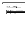
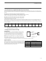
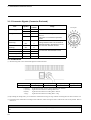
3-1-3 Connector Signals (Connector Enclosed)
Symbol
Pin
number
+24V
A
0V
B
+P
C
-P
D
RS-422A RD
(Receiving)
RD+
E
RD-
F
RS-422A SD
(Sending)
SD+
SD-
G
H
RS-232C Receiving
Rx
J
RS-232C Sending
Tx
K
RS-232C Signal 0 V
SG
L
Frame ground
GR
M
Item
Power supply
Setting
Usage
Pin Layout
Supply 24 VDC.
Short-circuit for setting mode. Refer to Section 6-1.
This pin is not connected in operation
mode.
Use for RS-422A communications. (Terminating resistance 220 Ω is connected to
both RD and SD in the Antenna.) Do not
connect when RS-232C is used.
Use for RS-232C communications. Do not
connect when RS-422A/485 is used.
Ground to 100 Ω or less.
3-1-4 Indicators
(1) The following items can be checked through the Antenna indicators.
Indicator
P (green)
C (red)
H (yellow)
T (green)
Meaning
Power supply
Radio wave emission
Host transmission
Tag transmission
P (Power):
C (Carrier):
H (Host):
T (Tag):
Lights when 24 VDC power is being supplied to the Antenna.
Lights when the Antenna is emitting radio waves.
Lights when the Antenna is sending data to the host.
Lights when the Antenna is sending data to a Tag.
(2) By enabling the setting mode, you can check the communications range for Tags without connecting the host. Refer to Section 4-4.
(3) If operation fails, troubleshoot according to these indicators, which will light or flash to indicate the cause of the problem. Refer to
Section 7-2.
Precaution for Correct Use
Do not disassemble the Antenna or touch the inside when the power supply is turned ON. Otherwise, the Antenna may
fail.
3-2
3-2 V690-D8KR01A ID Tag
3-2-1 Specifications
Item
Specifications
Memory capacity
8 Kbytes
Type of memory
SRAM (volatile memory). Data is backed up by a battery.
Battery life (Reference
value)
5 years
*At an ambient temperature of 25°C. For details, refer to Section 3-2-4.
The battery is not replaceable.
There is a battery voltage alarm function.
Ambient operating temperature
−20 to 60°C during communications, −25 to 70°C otherwise (with no icing)
Ambient operating humidity
35% to 85% (with no condensation)
Ambient storage temperature
−25 to 70°C (with no icing)
Ambient operating humidity
35% to 85% (with no condensation)
Degree of protection
IP67 (IEC60529) and IP67g (JEM1030)* When mounted on a flat surface without any level
difference.
Vibration resistance
10 to 2,000 Hz, single amplitude 0.75 mm, maximum acceleration 150 m/s2 sweeping 10
times for 15 minutes in X, Y, and Z directions
Shock resistance
500 m/s2 3 times each in X, Y, and Z directions, i.e., 18 times total
Weight
75 g max.
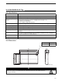
3-2-2 Dimensions
Case material
ABS resin
Fill resin
Epoxy resin
Two 4.5 dia mounting holes
13.8
86
8
44±0.2
54
76±0.2
(Unit: mm)
WARNING
A lithium battery is contained in an ID Tag. Do not disassemble, deform under pressure, heat to
above 212 °F (100°C), or incinerate the ID Tag. Otherwise serious injury may result from fire or
rupturing of the battery.
3-3
3-2 V690-D8KR01A ID Tag
3-2-3 Memory Map
♦ User Data
The memory capacity for user data on an ID Tag is 8,192 bytes. The minimum unit of memory is 1 byte and memory is specified using
addresses (0000h to 1FFFh). h: Hexadecimal number
Data address
Bit
7
6
5
0000h to
1FFFh
4
3
2
1
0
User data (8 kbytes)
Initial values: All 00h
Writing by
user
Related
commands
Possible
Section 6-7-1, 6-73 to 6-7-7
♦ System Data
In addition to user data, system data is included in the ID Tag memory. Uppercase words, such as DATE are used as addresses. For
details on reading and writing, refer to Section 6-7-1 to 6-7-5.
Content
Date of manufacture
ID code
Bit
7
6
5
4
3
2
1
Thousand’s place of Year
Hundred’s place of Year
Ten’s place of Year
One’s place of Year
Ten’s place of Month
One’s place of Month
Ten’s place of Day
One’s place of Day
8 bytes *A value inherent to the Tag.
0
Writing by
user
Not possible
Not possible
Write Protect
data
4 bytes *Refer to Section 4-6
Initial value: Write Protect disabled in all the areas.
Possible
Sleep waiting
time
2 bytes *Refer to Section 4-7.
Initial value: 4800 (8 minutes). Set in units of 100 ms.
Possible
3-4
Related commands
Section 6-7-1 and
6-7-3
Section 6-7-2
Section 6-7-1, 6-73 to 6-7-5
3-2 V690-D8KR01A ID Tag
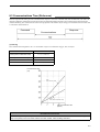
3-2-4 Battery Life Characteristics
The ID Tag contains a battery. The charts below show the relation between the ID Tag battery life, number of communications bytes,
and ambient temperature. The battery life is the time until the battery voltage alarm is given.
Communications Data and Battery Life (at an Ambient Temperature of 25°C)
Battery life
(Years)
8
7
Conditions
• Write (single trigger without verification)
• One Tag
• The Tag enters sleep mode after a command is
executed.
Example of command
[STX]0080W3SUAA0000 0100
[write_data] [ETX]
6
5
4
3
2
1
0
0
2
4
6
8
Communications data k bytes
(100 times/day)
Battery life
(Years)
Ambient Temperature and Tag Battery Life (256 bytes x 100 times/day)
Ambient temperature
3-2-5 Battery Voltage Alarm Function
When the voltage of the battery in an ID Tag becomes low, 7B will be returned as the end code when a Tag communications command
(Read or Write) is executed.
Precaution for Correct Use
After the end code 7B is first returned, the ID Tag can be used for approximately one month in normal situations. We recommend, however, that you replace the Tag with a new one immediately. If the ambient temperature is 0°C or lower, an
end code of 7B may be returned even if the battery has sufficient charge. End codes of 7B can generally be ignored if the
temperature is 0°C or lower.
3-5
3-3 V690-L01 RS-422A/485 Link Unit
3-3-1 Specifications
Item
Interface specifications
Power supply voltage
Allowable voltage
Power consumption
Operating temperature
Operating humidity
Storage temperature
Storage humidity
Insulation resistance
Withstand voltage
Degree of protection
Vibration resistance
Shock resistance
Ground
Weight
Specifications
RS-422A, RS-485
24 VDC
20.4 to 26.4 VDC
6 W max.
0 to 55°C (with no icing)
35% to 85% (with no condensation)
−10 to 65°C (with no icing)
35% to 85% (without condensation)
20 MΩ min. (at 100 VDC) between the cable terminals as a group and the case, excluding GR
1,000 VAC, 50/60 Hz for 1 minute, detected current of 20 mA or less between the cable terminals as a group and the case, excluding GR
IP30 (IEC60529) *When connected to connector on V690-A5@ Connecting Cable.
10 to 150 Hz, single amplitude 0.35 mm, maximum acceleration 50 m/s2 sweeping 10 times
for 8 minutes in X, Y, and Z directions
150 m/s2 3 times each in X, Y, and Z directions, i.e., 18 times total
Ground to 100 Ω or less.
450 g or less
3-3-2 Dimensions
Case material
SECC (Iron)
Antenna indicator
Operation indicator
Two 4.5-dia. mounting holes
(Unit: mm)
3-6
3-3 V690-L01 RS-422A/485 Link Unit
3-3-3 Function
The Link Unit functions as a relay when operation is controlled through RS-422A/RS-485 communications between the host and
Antenna. For an example of internal circuits, refer to Section 5-2-2.
Connect the connector
(D-sub 15-pin) of the
RS-422A/RS-485 Link
Unit Connecting Cable.
RUN Indicator
Lights when the
24 VDC power supply
is ON.
ANT PWR Indicator
Lights when 24 VDC
is supplied to the
Antenna.
Connect 24 VDC
power supply.
Connect RS-422A/RS-485
communications line.
Ground to
100 Ω or less.
Switch Functions
ANT PWR
SET UP
Turn ON to supply power to the
Antenna.
Turn ON to short-circuit the setting mode
terminals (+P and -P).
Turn OFF to turn
OFF the power to
the Antenna.
Turn OFF to open the
circuit between the
setting mode terminals (+P and -P).
RS-422A/
RS-485
Switches
between
RS-422A
and RS-485.
Connects/disconnects the
terminating resistance
(220 Ω) of RS-422A RD
(Receiving) for RS-422A
communications.
RS-422A SD (Sending)
RS-485
Connects/disconnects the
terminating resistance
(220 Ω) of RS-422A SD
(Sending) for RS-422A
communications.
The terminating resistance
cannot be turned ON/OFF
for RS-485 communications.
The terminating resistance
cannot be turned ON/OFF
for RS-485 communications.
RS-422A RD (Receiving)
Precautions for Correct Use
Always connect a grounding wire. Otherwise, errors may occur in operation.
Do not touch any terminal when the power supply is turned ON. Otherwise, an error may occur in operation.
Do not disassemble the Unit or touch the inside when the power supply is turned ON. Otherwise, the Unit may fail.
3-7
3-4 Connecting Cables
3-4-1 Specifications
Item
Specifications
Cable outer diameter
7.5 mm
Cable color
Dark gray
Sheathing material
Vinyl chloride resin
Number of cores
12 (Three AWG22 lines for power supply and GR and nine AWG26 lines for signals)
Insulation resistance
50 MΩ/km min. between the cables as a group and the cable sheath
Withstand voltage
500 VAC for 1 minute between the cables as a group and the cable sheath
3-4-2 Dimensions
(1) RS-232C Connecting Cables (for IBM PC/AT or Compatible)
Item
Specifications
Connector at Antenna
Round connector (watertight)
Connector at host
D-sub 9-pin, female (not watertight)
Model
Cable length
V690-A40
2m
V690-A41
3m
V690-A42
5m
V690-A43
10 m
V690-A44
15 m
Connection
label
Vinyl insulated round cord, 7.5 dia.
Connector for computer
Brown
Blue
Light Green
20 dia.
Connector for Antenna
Black
Green/Yellow
Cable length
Inch screw thread (M2.54)
3-8
(Unit: mm)
3-4 Connecting Cables
(2) RS-422A/485 Link Unit Connecting Cables
Item
Specifications
Connector at Antenna
Round connector (watertight)
Connector at Link Unit
D-sub 15-pin, male (not watertight)
Model
Cable length
V690-A50
2m
V690-A51
3m
V690-A52
5m
V690-A53
10 m
V690-A54
20 m
V690-A55
30 m
V690-A56
50 m
20 dia.
Cable length
Connector (at Antenna)
Metric screw
thread (M2.5)
Vinyl insulated round
cord 7.5 dia.
Connector (at Link Unit)
Connection
label
(Unit: mm)
3-9
3-5 Tag Communications Performance
Item
Specifications
Frequency
2,450 MHz band (microwave, 2,434.25 to 2,465.75 MHz)
Type of wireless station
Classified as a specified low-power wireless station - wireless equipment for mobile object
identification (RCR STD-29 Version 3.0) in Japan.
*The user is not required to apply for a license for a wireless station in Japan.
Transmission output at
modulation
5 mW for low-power (2 m) mode and 10 mW for high-power (5 m) mode
Polarized waves
Circularly polarized wave
Output power mode
(communications range)
Low-power (2 m) mode/high-power (5 m) mode switched by host command. (Section 4-2)
Low-power mode: 0.2 to 2.0 m (reference value)
High-power (5 m) mode: 0.2 to 5.0 m (reference value)
*Conditions for reference value
• Ambient temperature of 20±5°C
• Place the Tag at a suitable rotating position so that the logo “omron” is upright. (Refer to
the figure below.)
• Place the Tag on the center axis of the Antenna at a height of 1.5 m in a large room where
radio wave noise is minimal.
Communications speed
600 kbps
Communications error
check
16-bit CRC bidirectional check (CRC: Cyclic Redundancy Check)
Tag rotation: 0 degrees
Antenna
*The hatched area
Tag
on the Tag is the “omron” logo.
Precautions for Correct Use
• The communications range depends on the installation site environment. This is because metal materials and the
ground reflect a radio wave, and water and the human body absorb it. Place the Antenna and Tag in the communications range and check the radio wave environment in advance.
• The V690-HMG01A Read/Write Antenna has a communications test command to check the radio wave environment at
the working site. (Refer to Section 4-5.)
3-10
3-6 Host Communications Specifications
Item
Applicable standards
Specifications
RS-232C
RS-422A
RS-485
Remarks
Note 1
Communications method
Bidirectional half-duplex transmissions
Baud rate
4,800 bps, 9,600 bps, 19,200 bps, 38,400 bps,
57,600 bps, and 115,200 bps
Note 2
Synchronization method
Start-stop synchronization (1 or 2 stop bits)
Note 2
Transmission code
ASCII 7 bit or JIS 8 bit
Note 2
Maximum number of connected Antennas
32
Error control
Vertical parity (even, odd, none). Horizontal parity is used as BCC.
Line length
RS-232C: 15 m max.
RS-422A: 300 m max.
RS-485: 300 m max.
Note 2
Note 1. The Antenna is equipped with RS-232C and RS-422A terminals. Refer to Section 3-1-3. RS-422A/485 is connected through
the Link Unit.
Note 2. Switched by a command from the host. (Refer to Section 6-9-7.)
3-11
3-6 Host Communications Specifications
3-12
Chapter 4 Functions
4-1 Single, FIFO, and Multi Mode Access
You can use one of the three communications modes according to the number of Tags in the communications area and the situation. The
communications mode can be specified in the communications designation of a command.
(1) Single Mode
In Single mode, a communication is made with one Tag in the Antenna communications area. In Single mode, only one Tag must be in the Antenna communications
area. If two or more Tags are in the Antenna communications area, a communications error will occur.
(2) FIFO Mode (First-In First-Out)
FIFO mode enables accessing Tags entering the communications area sequentially
one by one. When the communication with one Tag has been completed, the Tag is
prohibited from communicating again. Even if there are Tags that have completed
communications in the Antenna communications area, a communication will be
made with the next Tag that entered the area. When a Tag prohibited from communicating has gone out of the Antenna communications area, communications with
that Tag will be enabled again.
(3) Multi Mode
Multi mode enables accessing all the Tags in the Antenna communications area. A
Selective Access function can be used to communicate only with specific Tags in
the Antenna communications area.
Precaution for Correct Use
When you use FIFO mode, do not allow more than one Tag to enter the Antenna communications area simultaneously. If
more than on Tag enters the Antenna communications area simultaneously, a communications error will occur and communications will not be possible until there is only one Tag in the Antenna communications area.
4-1
4-2 Switching between Low-power (2 m) and High-power (5 m) Mode
You can switch between the low-power (2 m) and high-power (5 m) output power mode by using a command from the host. Use either
one depending on the working site.
For information on the command, refer to Section 6-9-2 and 6-9-3. The default value is the low-power mode.
For information on the communications range for the low-power mode and high-power mode, refer to Section 8-1.
4-2
4-3 Radio Wave Channel Switching
In this RFID System, the 2,450 MHz frequency band frequencies from 2,437.5 to 2,462.5 MHz can be divided into 10 channels (at 2.5MHz intervals). Those channels can be switched using a command from the host. Use them to prevent mutual interference between
Antennas or interference caused by any other devices.
For information on the command, refer to Section 6-9-2 and 6-9-3. The default value is Channel 5 (2,450 MHz).
Channel
2,450 MHz frequency band
Laws and Standards
• Always use the low-power (2 m) mode when using the Antenna in the USA.
• Always use radio wave channel 5 when using the Antenna in Iceland, Ireland, England, Italy, Austria, the Netherlands,
Greece, Switzerland, Spain, Denmark, Norway, Finland, France, Belgium, or Luxemburg.
Precaution for Correct Use
Due to frequency dispersion, adjacent channels may overlap each other. Do not assign consecutive numbers to the
channels of adjacent Antennas.
4-3
4-4 Simplified Communications Test
You can check communications between an Antenna and Tag using the Antenna only without connecting to the host.
In the simplified communications test, the Antenna detects the Tag approximately every 2 seconds and, if the Tag responds, it lights the
C indicator.
(1)
(2)
(3)
(4)
Turn OFF the power supply.
Short-circuit the setting terminals +P and -P.
Turn ON the power supply. The setting mode will be enabled. (Refer to Section 6-1.)
The simplified communications test will start. As shown below, the C indicator (radio wave emission) shows whether communications with the Tag are successful.
(5) The communications test will stop when any command is sent from the host to the Antenna.
Antenna indicators
P (green)
C (red)
H (yellow)
T (green)
Power
supply
Radio
wave
emission
Host transmission
Tag transmission
Lit
Flashing
Not lit
Flashing
C and T flash approximately every 2 seconds. This shows that
there is no Tag.
Lit
Lit
Not lit
Flashing
C lights. This shows that there is a Tag in the Antenna communications area.
Meaning
Flashing: Flashing approximately every 2 seconds. (This shows that data is being sent.)
4-4
4-5 Communications Test
Execute the communications test to check the radio wave environment at the working site.
Data (256 bytes) is communicated 256 times between the Antenna and Tag and the communications status is output. A total of
128 kbytes of data is communicated in two directions. A few seconds is required to execute this test. Communications are not retried.
Refer to Section 6-7-8.
(1)
(2)
(3)
(4)
(5)
(6)
(7)
Create a communications program at the host.
Enable the operation mode. (Disconnect the terminals +P and -P from each other. Refer to Section 6-1.)
Turn ON the power supply.
Put the Tag in front of the Antenna.
Send a communications test command (Section 6-7-8). If the Antenna is 00, the command is [STX]0080T0SU[ETX].
If the Antenna responds to the host, the communication between the host and Antenna was made successfully.
In the response [STX]8000T0000256@@[ETX], the radio wave environment value @@ will be between 0000 and 0256. If the value
is close to 0000, communications with the Tag are stable.
Example of response from Antenna:
*Radio wave environment is good.
[ STX] 8 0 0 0 T 0 0 0 0 2 5 6 0 0 0 0 [ ETX ]
Number of
Radio wave
communications environment value
*Radio wave environment is poor or there is no Tag is in the communications area.
[ STX] 8 0 0 0 T 0 0 0 0 2 5 6 0 2 5 6 [ ETX ]
Number of
Radio wave
communications environment value
Precaution for Correct Use
We recommend you to maintain a radio wave environment value of 50 or less.
4-5
4-6 Write Protect Function
You can enable write protection for user data (8 kbytes) for each page (256 bytes). Write protection prevents data from being destroyed
by accidental writing.
♦ Scope of Write Protection
The addresses of pages P0 to P31 are listed below.
Page
256 bytes/page
P0
0000 to 00FF (h)
P1
0100 to 01FF (h)
P2
0200 to 02FF (h)
.
.
.
.
.
.
P30
1E00 to 1EFF (h)
P31
1F00 to 1FFF (h)
256 bytes x 32 pages = 8,192 bytes
*(h) means that the value is a hexadecimal number.
♦ Enabling Write Protection
The 32 bits of Write Protection data (4 bytes) in the system data (refer to Section 3-2-3) correspond to the pages of Tag memory. A page
can be write-protected by setting the bit corresponding to the page to 1 (enable). To disable write protection, clear the bit to 0.
The relation between the bits in write protection data and pages is shown below.
Write protection data (4 bytes)
Code
Bit
7
6
5
4
3
2
1
0
A1
P7
P6
P5
P4
P3
P2
P1
P0
A2
P15
P14
P13
P12
P11
P10
P9
P8
A3
P23
P22
P21
P20
P19
P18
P17
P16
A4
P31
P30
P29
P28
P27
P26
P25
P24
P**: Status of write protection for page ** (between 0 and 31).
4-6
Description
Status of Write Protection
0: Disabled (Default
value)
1: Write-protected
4-6 Write Protect Function
♦ Examples of Write Protection
(1) The write protection data to write-protect pages P3 and P14 in the initial state of the ID Tag would be as follows:
Write-protects P14
Write-protects P3
Binary notation
Hexadecimal
notation
The Write command (Section 6-7-4) would be as follows:
Command code
Communications
designation
Split
flag
Data designation
Start address
Number of write bytes
Write data
The response from the Antenna for a normal end would be as follows:
Command code
End code
Response number
ID code
(2) The write protection data to disable write protection for page P14, which was write-protected in the step (1), and to write-protect
P17 and P28 would be as follows:
Write-protects P28
Write-protects P17
Clears protection for P14
Decimal notation
Hexadecimal
notation
The Write command (Section 6-7-4) would be as follows:
Command code
Communications
designation
Split
flag
Data designation
Start address
Number of write bytes
Write data
(3) The write protection data to disable write protection for all pages would be as follows:
Decimal notation
Hexadecimal
notation
The Write command (Section 6-7-4) would be as follows:
Command code
Communications
designation
Split
flag
Data designation
Start address
Number of write bytes
Write data
4-7
4-7 ID Tag Power-Saving Functions
The Tag has the two power-saving functions.
♦ Preventing Battery Power Loss Due to Radio Wave from Other Radio Equipment
This function operates constantly. No settings are necessary.
If any radio equipment is located near a Tag, the Tag will operate (i.e., it will become ready to communicate) because the Tag’s receiving
band is wide. As a result, the Tag’s battery may be consumed. (Refer to Interference with Second-generation Low-power Data Communications
Systems (Wireless LANs), Cellular Phones, etc. at the beginning of this manual.) To prevent this power loss, the Tag has a function to enter a
sleep state (refer to Appendix 1 Glossary) against radio waves emitted from any other wireless equipment.
• The V690 Antenna sends a wake command (refer to Appendix 1 Glossary) every 100 ms after emitting radio waves and the Tag
operates (i.e., it will become ready to communicate).
• When the Tag receives radio waves from any other wireless equipment, the Tag may operate (i.e., it will become ready to communicate), but unless it receives a valid wake command, the Tag will return to a sleep state in 2 seconds.
Wake command
100 ms
ON
Antenna radio wave emission
OFF
Even if there is no command from the host, the Antenna sends a wake command every 100 ms while emitting radio waves.
Operates (ready to operate)
Tag
Sleep
2 s (fixed)
If the Tag receives a valid wake command within 2 seconds
after it starts operation, the Tag will not sleep.
Operates (Ready to operate)
Tag
Sleep
2 s (fixed)
If the Tag does not receive a valid wake command within 2
seconds after it starts operation, the Tag sleeps.
4-8
4-7 ID Tag Power-Saving Functions
♦ Prevent Battery Power Loss Due to Neglect
This function operates constantly. No settings are necessary.
When you use the Antenna with a Repeat command (refer to (3) in Section 6-2-1), troubles at the working site may cause the Tag to be
left in front of the Antenna while it is emitting radio waves, causing the Tag to operate (ready to operate). Here again, the Tag’s battery
will be consumed. To prevent this power loss, the Tag has a function to enter a sleep state when a waiting time for sleeping (refer to a
chart below) has passed.
If the Tag does not receive a valid command within the waiting time for sleeping after receiving a valid command, the Tag enters a sleep
state. A default value of the waiting time for sleeping is 480 seconds (8 minutes). To change the waiting time, specify “SLEP” as the
address in the Read/Write command. The wait time can be set to between 0000 and 9999 in units of 0.1 s, e.g., 0001 × 0.1 s = 0.1 s and
4800 × 0.1 s = 480 s. A setting of 0000 sets an infinite time. (Refer to Section 6-7-1 and 6-7-3 to 6-7-5.)
To wake the Tag from the sleep state:
• Turn OFF the power supply of the Antenna and turn it ON again.
• Take the Tag out of the communications area and place it in the communications area again.
Antenna radio wave emission
(A radio wave is being emitted)
Command process
Tag
Operates (ready to operate)
Sleep
Waiting time for sleeping
4-9
4-7 ID Tag Power-Saving Functions
4-10
Chapter 5 Installation and Connection
5-1 Read/Write Antenna and ID Tag
5-1-1 Installation Environment
(1) Antenna and Tags
Install the Antenna and Tags so that the front sides of the Antenna and Tags face each other. Confirm the front sides and back sides. The
front sides must face each other.
Tag
Antenna
Front side
Front side
(2) Antennas
Keep sufficient distance between the Antennas according to Section 8-4. If sufficient distance cannot be obtained perform the following:
• Assign the most different channel numbers to the radio channels of adjacent Antennas. (Refer to Section 4-3.)
• Permit only one of Antennas to transmit radio waves at a time so that the Antennas do not transmit radio waves simultaneously.
(3) Tag Rotation in Respect to the Antenna
The Antenna and Tag use circularly polarized waves as radio waves to communicate with each other. The Tags can communicate with
the Antenna at any angle of rotation.
• Conceptual Diagram of Circularly Polarized Waves
The arrows show the direction to the oscillating surface. The radio wave propagates while the oscillating surface is rotating.
Tag
Antenna
*The hatched area
on the Tag indicates the “omron” logo.
5-1
5-1 Read/Write Antenna and ID Tag
(4) Installation Environment
Do not install the Antenna and Tags in any of the following locations:
• Locations where the ambient temperature is no between −20 and 60°C for the Antenna and −25 and 70°C for the Tag, where the temperature fluctuates considerably, or where condensation can occur
• Locations where the relative humidity not between 35% and 85%
• Locations where there is corrosive gas, flammable gas, dust, salt, or iron powder
• Locations subject to vibration or shock
• Locations subject to splashes of water, oil, or chemicals
5-1-2 Installing the Antenna
Install an Antenna on a flat plane, taking care not to bend it by applying excessive force. As shown below, mount the Antenna with four
M5 screws, spring washers, and flat washers. The tightening torque is 2.0 N•m (approximately 20 kgf•cm). Do not use any lock paint to
fix the screws.
Spring washer
Flat washer
(Unit: mm)
Precaution for Correct Use
Do not disassemble the Unit or touch the inside when the power supply is turned ON. Otherwise, the Unit may fail.
5-2
5-1 Read/Write Antenna and ID Tag
5-1-3 Rainproofing the Antenna
The Antenna is not waterproof. Do not install the Antenna outdoors or in any other location where it would be subject to water without
waterproofing it.
If you must install the Antenna outdoors, protect the Antenna against rain with a plastic rainproof box. To prevent water droplets entering the Antenna through a cable, be sure to turn the Antenna cable section downward.
Gap between the Antenna surface and window plate is 10 to 20 mm.
Example of Protection Box
Cover the window with a
plate 3 mm in thickness that
radio waves can penetrate
easily, e.g. an acrylic plate.
Size enough to cover
the entire Antenna
including connector.
If the box is metallic, make
a window in the box. The
window size should be the
same as the Antenna.
Drill a large hole for ventilation
and drainage.
Clamp it to prevent the connector
being pulled directly.
Precaution for Correct Use
The protective structure IP62 of the Antenna is for protection against the drops of water. If the Antenna is splashed with
water spray or water jet flow, cover the Antenna with a protection plate. (Refer to Appendix 3 Degree of Protection.)
5-3
5-1 Read/Write Antenna and ID Tag
5-1-4 Install Tags
♦ Installation
Install a Tag on a flat plane taking care not to bend it by applying excessive force. As shown below, mount the Tag with two M4 screws,
spring washers, and flat washers. The tightening torque is 1.2 N•m (approximately 12 kgf•cm). Do not use any lock paint to fix the
screws.
Spring washer
Flat washer
(Unit: mm)
♦ Influence on Communications: Adhesive, Metal Tape, Water Films, Etc.
• When you apply adhesive or other substances to the surface of a Tag, radio waves are attenuated and the communications area may
be affected. Performs a communications test under application conditions in advance.
• If a metallic tape is attached to the surface of a Tag, radio waves will be interrupted and communications with the Antenna will fail.
• If the Tag is put on a glass plate with double-sided adhesive tape as shown below, the gap between the glass plate and Tag sweats easily. Moreover, a water film may be generated. In this case, radio waves will be absorbed and the communications range may become
smaller.
Double-sided adhesive tape
ID Tag
Glass plate
5-4
5-1 Read/Write Antenna and ID Tag
5-1-5 Connecting the Cable to the Antenna
To connect the Antenna and host, use a Connecting Cable (sold separately).
RS-232C Connecting Cable
V690-A4@ *Refer to Section 3-4.
RS-422A/485 Link Unit Connecting Cable
V690-A5@ *Refer to Section 3-4.
(1) When you connect the connector on the cable and connector on Antenna, be sure to hold those connectors and insert them into each
other completely.
(2) When you have connected the connectors, turn the ring completely as shown below.
Antenna connector
Connecting Cable
Ring
Precautions for Correct Use
• Do not connect or disconnect the connectors when the power supply is ON. Otherwise, product failure may result.
• Do not pull the cable with excessive force.
• Do not touch the connecting terminals on the connector.
• Do not touch the connector during operation.
5-5
5-2 Wiring the Host
5-2 Wiring the Host
5-2-1 Wiring an RS-232C Interface
(1) Using RS-232C Connecting Cable
To connect a Read/Write Antenna to an IBM PC/AT or compatible, use a V690-A4@ RS-232C Connecting Cable. Connect the five electric wires at a connector of host as shown below.
RS-232C Connecting Cable (V690-A4@)
IBM PC/AT or compatible
V690-HMG01A
Antenna
Ground to
100 Ω or
less
Switch,
etc.
24 VDC
power
supply
• Recommended 24 DC Power Supply
S82K-01524 (Output: 24 VDC, 0.6 A. Input: 100 to 240 VAC, OMRON)
UL Class 2 Power Supply
Connecting the Leader Lines of RS-232C Connecting Cable
Leader lines of Connecting Cable
Brown
Thick wire: AWG22
Blue
Light green
Black
Green/Yellow
Details of connection
(+) of 24 VDC power supply
(-) of 24 VDC power supply
Thin wire: AWG26
+P and -P for the setting mode: Open for operation mode.
Short-circuit for setting mode.
Thick wire: AWG22
Ground to 100 Ω or less.
Connector Pin Layout
Pin
No.
IBM PC/AT or
compatible
V690-A4@
RS-232C Connecting Cable
Socket (Male)
Plug (Female)
1
2
RD (Receiving)
TX (Sending)
3
SD (Sending)
RX (Receiving)
SG (Signal ground)
SG (Signal ground)
4
View from connecting side
5
6
7
RS (Request to send)
8
CS (Clear to send)
9
5-6
Loop back (Short-circuit)
5-2 Wiring the Host
(2) Using RS-232C Connecting Cable to Extend a Cable and Connecting to IBM PC/AT or Compatible (Typical)
To connect an IBM PC/AT or compatible (typical) extending a RS-232C Connecting Cable, prepare the cables as shown below.
The wires in the cable must be AWG26 or thicker.
Cable prepared by customer
RS-232C Connecting Cable (V690-A4@)
IBM PC/AT or compatible
Ground to
100 Ω or
less
Switch,
etc.
DC 24 V
power
supply
• Recommended 24 VDC Power Supply
S82K-01524 (Output: 24 VDC, 0.6 A. Input: 100 to 240 VAC, OMRON)
If you do not use the recommended power supply or an equivalent, connect to the 24 VDC power supply via a line filter.
Pin No.
IBM PC/AT or compatible
(typical)
Socket (Male)
Cable prepared by customer
Female
Male
V690-A4@
RS-232C Connecting Cable
Plug (Female)
RD (Receiving)
TX (Sending)
SD (Sending)
RX (Receiving)
SG (Signal ground)
SG (Signal ground)
RS (Request to send)
CS (Clear to send)
Loop back
5-7
5-2 Wiring the Host
(3) Connecting to an OMRON PLC
To connect an Antenna and OMRON Programmable Controller (PLC), prepare a V690-A4@ RS-232C Connecting Cable and connection cable.
The wires in the cable must be AWG26 or thicker.
RS-232C Connecting Cable (V690-A@)
Cable prepared by customer
OMRON PLC
Ground to
100 Ω or
less.
Switch,
etc.
24 VDC
power
supply
• Recommended 24 DC Power Supply
S82K-01524 (Output: 24 VDC, 0.6 A. Input: 100 to 240 VAC, OMRON)
UL Class 2 Power Supply
Pin No.
OMRON PLC
Socket (Female)
Cable prepared by customer
Male
Female
RS-232C Connecting Cable
Plug (Female)
SD (Sending)
TX (Sending)
RD (Receiving)
RX (Receiving)
RS (Request to send)
CS (Clear to send)
Loop back
(Short-circuit)
SG (Signal ground)
Loop back
SG (Signal ground)
5-8
5-2 Wiring the Host
5-2-2 Wiring for RS-422A/485
(1) 1:1 Connection with Link Unit
To connect an Antenna and host through an RS-422A/485 connection, use the Link Unit. The following example shows the connection
of one Antenna and one host through RS-422A (4-wire).
Microwave
Antenna
Station No.
00
RS-422A/485 Link Unit Connecting Cable
Host
Link Unit
24 VDC
grounding
Host settings
*RS-422A
(4-wire)
*Terminating
resistance
RD ON
SD ON
Link Unit settings
*RS-422A
(4-wire)
*Terminating
resistance
RD ON
SD ON
5-9
5-2 Wiring the Host
The internal configuration of a 1:1 connection of an Antenna and host through RS-422A (4-wire) is shown below.
• The signal lines (Rx, Tx and SG) of RS-232C are disconnected.
• If RS-422A is selected with the Link Unit, SD and RD terminating resistance (220 Ω) can be turned ON/OFF.
Antenna
Power supply circuit
Setting
mode
RS-232C circuit
Grounding
RS-422A circuit
Microwave
Antenna
Station No. 00
RS-422A/485
Link Unit Connecting Cable
Cut in connector.
Link Unit
Link Unit
Antenna
power
supply
switch
Setting switch
When switching
RS-422A
24 VDC
5-10
0V
5-2 Wiring the Host
(2) 1:N Connection with Link Unit
To connect several Antennas and the host through RS-422A/485 connections, use Link Units. The following example shows the connection of several Antennas and one host through RS-485 (2-wire).
A maximum of 32 units can be connected.
Microwave
Antenna
Station No.
00
Microwave
Antenna
Station No.
01
Microwave
Antenna
Station No.
31
Link Unit
Link Unit
Link Unit
RS-422A/485 Link
Unit Connecting
Cable
Host
24 VDC
grounding
24 VDC
grounding
24 VDC
grounding
Host settings
Link Unit settings
Link Unit settings
Host Settings
*RS-485
(2-wire)
*RS-485
(2-wire)
*RS-485
(2-wire)
*RS-485
(2-wire)
*Terminating
resistance ON
*Terminating
resistance
OFF
*Terminating
resistance
OFF
*Terminating
resistance ON
Precaution for Correct Use
Turn ON (connected) the terminating resistances at both ends of the entire RS-422A/RS-485 communications wiring.
5-11
5-2 Wiring the Host
Precaution for Correct Use
The host must send the next command within 10 ms after checking a response from an Antenna. When you use an RS232C/485 converter at the host, the command must be sent after the command transmission has been enabled completely. When the command has been sent completely, switch into the receiving state within 10 ms. Otherwise, communications with the Antenna may fail.
Host
Command frame
Command frame
(1st time)
(2nd time)
V690-HMG01A
Read/Write Antenna
Signal
name
Response frame
V690-A5@
Link Unit connector
pin number
Antenna connector
pin number
+24V
1
A
0V
2
B
+P
3
C
-P
4
D
RD+
5
E
RD-
6
F
SD+
7
G
SD-
8
H
GR
12
M
5-12
5-2 Wiring the Host
The internal configuration of the 1:N connection of an Antenna and host through RS-485 (2-wire) is shown below.
• The signal lines (Rx, Tx and SG) of RS-232C are disconnected.
• If RS-485 is selected with the Link Unit, the terminating resistance (220 Ω) can be turned ON/OFF.
Antenna
Power supply circuit
Setting
mode
RS-232C circuit
Grounding
RS-422A circuit
Microwave
Antenna
Station No. 00
Cut in connector.
RS-422A/485
Link Unit Connecting Cable
Link Unit
Link Unit
Antenna
power
supply
switch
Setting switch
When switching
RS-485
24 VDC
0V
5-13
5-3 Link Unit
5-3 Link Unit
5-3-1 Installation Environment
♦ Installation site
Do not install a Link Unit in any of the following locations:
• Locations where the ambient temperature is no between 0 and 55°C, where the temperature fluctuates considerably, or where condensation can occur
• Locations where the relative humidity not between 35% and 85%
• Locations where there is corrosive gas, flammable gas, dust, salt, or iron powder
• Locations subject to vibration or shock
• Locations subject to splashes of water, oil, or chemicals
♦ Assembly in a Panel
The ambient operating temperature of a Link Unit is 0 to 55°C. The following conditions must be met.
• Provide sufficient space for ventilation.
• Do not install the Link Unit near by any heat sources (heaters, transformers, and large-sized resistors).
• If the ambient temperature rises to 55°C or higher, install a ventilating fan or air conditioner to keep the temperature at 55°C or less.
• If you wire power lines (e.g., for high currents to drive motors) near the Link Unit, perform a communications test fully to check the
influence of noise and wire the power lines with care.
5-3-2 Installing Link Units
Install a Link Unit on a flat plane taking care not to bend it by applying excessive force. As shown below, mount the Antenna with two
M4 screws, spring washers, and flat washers. The tightening torque is 1.2 N•m (approximately 12 kgf•cm).
Spring washer
Flat washer
(Unit: mm)
5-14
5-3 Link Unit
5-3-3 Wiring Link Units
♦ Connecting RS-422A/485 Link Unit Connecting Cable
Connecting:
(1) Always hold the connector on the Connecting Cable to the Link Unit and insert it into the Link Unit completely.
(2) When you have inserted the connector into the Link Unit, tighten the two lock screws with a Phillips screwdriver to secure it.
(3) Attach the enclosed ferrite core to the Connecting Cable. Close the ferrite core and lock it completely.
Ferrite core
Within 10 cm
Disconnecting:
(1) To disconnect the connector, loosen the two lock screws completely and pull the connector out straight, holding the connector hood.
(2) If the connector is hard to pull out, push the Link Unit while pulling out the connector.
Precaution for Correct Use
Be sure to connect a grounding wire. Otherwise, an error may occur in operation.
Do not touch any terminal when the power supply is ON. Otherwise, an error may occur in operation.
Do not disassemble the Unit or touch the inside when the power supply is turned ON. Otherwise, the Unit may fail.
5-15
5-3 Link Unit
♦ Connecting the Power Supply, Ground Wire, and Signal Wires
M3 screws are used for the power supply, ground, and signal terminals. For crimp terminals, use either one of those listed below. The
tightening torque is 0.6 N•m (approximately 6 kgf•cm).
• Applicable Crimp Terminals
Applicable wire
AWG22 to AWG16
Type
Forked
(For M3)
• Recommended 24 VDC Power Supply
S82K-01524 (Output: 24 VDC, 0.6 A. Input: 100 to 240 VAC. OMRON)
UL Class 2 Power Supply
• Ground GR to 100 Ω or less.
(Example of connection)
+24 VDC
0V
Ground to 100 Ω or less.
Precaution for Correct Use
If excessive noise is superimposed on the power supply line, supply power through a line filter. A line filter will considerably reduce ground noise.
5-16
5-3 Link Unit
♦ Connecting Signal Wires
To suppress noise, attach the enclosed ferrite core to the signal lines as shown below.
(1) Wire the signal wires.
(2) Put the signal wires together and wind the signal wires round the ferrite core once to prevent the ferrite core from moving. Position
the ferrite core within 10 cm from the Link Unit.
Put the signal wires together.
(3) Close the ferrite core and lock it completely.
Within 10 cm
To the host
♦ After completing wiring, attach the enclosed terminal block cover.
Enclosed terminal block cover
5-17
5-3 Link Unit
5-3-4 Switch Settings
Turn ON/OFF the switches with the enclosed plastic screwdriver. By default, all the
switches are set to OFF or RS-485.
(Enclosed plastic screwdriver)
♦ Enabling Setting Mode (Refer to Section 6-1)
(1) Turn OFF the ANT PWR switch (A) (see next page).
(2) Turn ON the SET UP switch (B).
(3) Turn ON the ANT PWR switch (A). → The ANT PWR indicator will light and setting mode will be enabled.
♦ Enabling Operation Mode (Refer to Section 6-1)
(1) Turn OFF the ANT PWR switch (A) (see next page).
(2) Turn ON the SET UP switch (B).
(3) Turn ON the ANT PWR switch (A). → The indicator ANT PWR will light and operation mode will be enabled.
♦ Enabling RS-422A communications
(1)
(2)
(3)
(4)
(5)
Turn OFF the 24 VDC power supply to the Link Unit (see next page).
Set the RS-422A/RS-485 switch (C) to RS-422A.
Turn ON or OFF the terminating resistance of RS-422A RD (D) and RS-422A SD (E) as required by the system configuration.
Connect the signal line terminals.
Turn ON the 24 VDC power supply to the Link Unit.
♦ Enabling RS-485 Communications
(1)
(2)
(3)
(4)
(5)
Turn OFF the 24 VDC power supply to the Link Unit (see next page).
Set the RS-422A/RS-485 switch (C) to RS-485 to disable RS-422A RD (D).
Turn ON or OFF the terminating resistance of RS-422A SD (E) as required by the system configuration.
Connect the signal line terminals.
Turn ON the 24 VDC power supply to the Link Unit.
5-18
5-3 Link Unit
Connect the connector (D-sub 15-pin) on
the RS-422A/RS-485
Link Unit Connecting
Cable (V690-A5@).
RUN Indicator
Lit when the 24 VDC
power supply is ON.
ANT PWR Indicator
Lit when 24 VDC is
supplied to the
Antenna.
Connect 24 VDC
power supply.
Connect RS-422A/RS-485
communications lines.
Ground to
100 Ω or less.
Switch Functions
(A)
(B)
(C)
(D)
(E)
ANT PWR
SET UP
RS-422A/RS-485
RS-422A RD
(Receiving)
RS-422A SD (Sending)
RS-485
5-19
5-3 Link Unit
5-20
Chapter 6 Controlling Operation from the Host
6-1 Operation Status of Read/Write Antenna and ID Tags
The Antenna in a V690 Series RFID System communicates with a Tag according to commands (1) sent from the host and returns the
results to the host as responses (3).
Host
Communications line
ID Tag
Read/Write Antenna
Commands
Communications between
the Antenna and Tag
Responses
♦ Operation Mode and Setting Mode of Antenna
Two modes are available in the operation of the Antenna. The available commands depend on the mode. Refer to Section 6-4.
Antenna station
Mode
Entering the mode
Description
Host communications
number
Operation
mode
Setting mode
Disconnect the two Antenna
terminals +P and -P and
reset the power supply (turn
OFF the power supply once
and turn it ON again).
Short-circuit the two
Antenna terminals +P
and -P and reset the
power supply.
Use for normal operation.
Settings can be
changed.
(Refer to
Section 6-9-7.)
00 to 31
(initial value 00)
• A simplified communications function (without connection to the
host) is available. Refer
to Section 4-4.
• Tag communications
commands and radio
wave transmission ON/
OFF commands cannot
be used.
Fixed settings.
(Refer to
Section 6-9-7.)
Use when the host
communications settings are unknown.
99
♦ Tag Status after Command Execution
Two modes are available after a command has been executed.
Mode
How to change mode
Description
Sleep state
Specify S@ or R@ in the communications designation of the command.
• Tag battery power can be saved.
• A Tag cannot be started within 0.2 seconds after
entering sleep state.
• Use for FIFO (First-In First-Out) communications. Refer to (3) of Section 6-2-1.
Standby state
Specify W@ or C@ in the communications designation of the command.
• Use when several commands are executed consecutively for one Tag.
6-1
6-2 Communications Operation Sequences
Operation sequences, such as communications with a Tag and response return timing, depend on the designations made with commands.
Designations must be made according to the Tag status in the Antenna communications area and the type of communications with the
host.
6-2-1 Communications Modes with Commands
(1) Trigger
With a Trigger command, a communication is performed with the Tag in the Antenna communications area when a command is
received. Check that the Tag is in the Antenna communications area before executing the command. If there is no Tag in the Antenna
communications area when the command is executed, the Antenna will return an error response.
After the command is executed, the Tag will enter sleep mode or standby mode.
• Sleep Mode (Communications Designation: SU or SN)
The Tag battery power can be saved in sleep mode. The Tag cannot be started within 0.2 seconds after entering sleep state.
• Standby Mode (Communications Designation: WU or WN)
Use the standby mode to execute several commands consecutively for one Tag.
Host
Antenna
Tags
No tag present
Trigger command
(1)The host must check that the Tag is in the
Antenna communications area and then
execute the command.
Tag
Communications process
(2)The Antenna communicates with the Tag
according to the command.
Tag
Sleep or
standby
Response
(3)When processing has been completed, the
Antenna returns a response saying that
processing has been completed to the
host and waits for another command.
Command process ended
Precaution for Correct Use
In Trigger Mode, always confirm that a Tag is in the Antenna communications area before executing a command.
6-2
6-2 Communications Operation Sequences
(2) Single Auto
With a Single Auto command, the Antenna will wait until a Tag enters the communications area and then communicates with the Tag.
To end Single Auto Mode, perform one of the following:
• Execute an Auto Repeat Cancel command (C2). The Antenna will leave Single Auto Mode and wait for a command.
• Execute any other command. The Antenna will leave Single Auto Mode and execute the new command. If the command format is
wrong, the Antenna will return a format error response of 14 and leave Single Auto Mode.
• If a waiting time is set for a Tag (refer to Section 6-9-4), the Antenna will return a no-Tag error response of 72 and leave Single Auto
Mode when the waiting time for the Tag has expired.
After the command is executed, the Tag will enter sleep mode or standby mode.
• Sleep Mode (Communications Designation: SU or SN)
The Tag battery power can be saved in sleep mode. The Tag cannot be started within 0.2 seconds after entering sleep state.
• Standby Mode (Communications Designation: WU or WN)
Use the standby mode to execute several commands consecutively for one Tag.
Host
Antenna
Tags
Single Auto
command
Waits for Tag
Waits for Tag
approaching
Communications process
No tag
present
(1)A Single Auto command is sent from the
host.
(2)The Antenna does not return a response
until the Tag approaches. The host waits
for the response.
No tag
present
Tag
Sleep or
standby
(3)When the Tag passes the front of the
Antenna, the Antenna communicates
with the Tag according to the command.
Response
Command process ended
Pass
(4)When processing has been completed, the
Antenna returns a response saying that
processing has been completed to the
host and waits for another command.
6-3
6-2 Communications Operation Sequences
(3) Repeat
When a Repeat command is received by the Antenna from the host, the Antenna will wait for a Tag, communicate with the Tag whenever the Tag enters the Antenna communications area, and return responses to the host.
If the sleep state (S@) is specified in the communications designation when the command is executed, FIFO (First-In First-Out) communications will be performed. (Refer to Section 4-1).
To end Repeat Mode, perform one of the following:
• Execute an Auto Repeat Cancel command (C2). The Antenna will leave Repeat Mode and wait for a command.
• Execute any other command. The Antenna will leave Repeat Mode and execute the new command. If the command format is wrong,
the Antenna will return a format error response of 14 and leave Repeat Mode.
• If a waiting time is set for a Tag (refer to Section 6-9-4), the Antenna will return a no-Tag error response of 72 and leave Repeat
Mode when the waiting time for the Tag has expired.
Host
Antenna
Tags
Repeat command
(Waits for Tag)
(Waits for Tag)
(1)A Repeat command is sent from the host.
(2)The Antenna does not return a response until the Tag
approaches.
No Tag present
No Tag present
(Waits for a response)
Communications process
Tag 1
Sleep
Response
Receives a
response
(3)When a Tag passes the front of the Antenna, the
Antenna communicates with the Tag according to the
command.
(4)When processing has been completed, the Antenna
returns a response saying that communication have
been completed to the host and waits for another Tag.
Pass
(Waits for Tag)
Pass
(Waits for a response)
Communications process
Tag 2
Sleep
Response
Receives a
response
(Waits for Tag approaching)
Pass
(Waits for a response)
Waits for Tag
6-4
No Tag present
(5)When another Tag passes the front of the Antenna, the
Antenna communicates with the Tag.
(6)When processing has been completed, the Antenna
returns a response saying that communications have
been completed to the host and waits for another Tag.
6-2 Communications Operation Sequences
6-2-2 Communications Modes with Communications Designations
(1) Polling Designation
If a normal auto command is used when one host controls several Antennas, a response is returned when Tag communications have been
completed. Several Antennas will return a response. With a Polling designation, the Antenna will return the response only at the request
of the host. This prevents more than one response from being returned simultaneously so that several Antennas can be controlled.
To terminate polling, perform one of the following:
• Execute an Auto Repeat Cancel command (C2). The Antenna will discontinue Polling Auto/Polling Repeat and wait for a command.
• Execute any other command. The Antenna will leave the polling mode and execute the new command. If the command format is
wrong, the Antenna will return a format error response of 14 and discontinue Polling Auto/Polling Repeat.
• If a waiting time is set for a Tag (refer to Section 6-9-4), the Antenna will return a no-Tag error response of 72 and discontinue Polling Auto when the waiting time for the Tag has expired. For Polling Repeat, the Antenna will return an error response and continue
Polling Repeat.
After the command is executed, the Tag will enter sleep mode or standby mode according to the communications designation (C@ or
R@).
Host
Antenna
Station No. 00
Tags
Antenna
Station No. 01
Tags
Polling Auto command
Station No. 00
Polling response
No Tag
present
Receives a response
Polling Auto command
Station No. 01
(Waits for Tag)
Polling response
No Tag
present
Receives a response
Requests a response
Station No. 00
(Waits for Tag)
Response of “No Tag”
No Tag
present
Receives a response
Requests a response
Station No. 01
(Waits for Tag)
Response of “No Tag”
No Tag
present
(1)A Polling Auto command is sent from
the host to the Antenna station No. 00.
(2)Immediately after receiving the command, the Antenna returns a response
saying the command has been accepted.
(3)A Polling Auto command is sent from
the host to the Antenna station No. 01.
(4)Immediately after receiving the command, the Antenna returns a response
saying the command has been accepted.
(5)The host can inquire about the progress
of process using a response request. If a
Tag has not yet approached, a response
of “No Tag” is returned to the response
request.
(6)When a Tag passes the front of the
Antenna station No. 00, the Antenna station No. 00 communicates with the Tag.
Receives a response
Communications process
(7)When the response request is sent to an
Antenna that had completed communications with a Tag, the Antenna returns a
response giving the processing results
and waits for another command.
Tag
Requests a response
Station No. 00
Response
Pass
(Waits for Tag)
Receives a response
Requests a response
Station No. 01
Response of “No Tag”
Receives a response
No Tag
present
(Waits for Tag)
6-5
6-2 Communications Operation Sequences
(2) Multi
With a Multi command designation, communications can be made with all the Tags in the Antenna communications area. Multi Trigger
and Multi Repeat commands are supported.
With a Multi Trigger command, the Antenna communicates with all the Tags in the communications area when it receives a command.
When processing has been completed, the Antenna will return a communications end response (end code 72).
With a Multi Repeat command, the Antenna will wait for a Tag after it receives a command. The Antenna continues to communicate
with all the Tags entering the communications area.
To terminate Multi Repeat, perform one of the following:
• Execute an Auto Repeat Cancel command (C2). The Antenna will discontinue Multi Repeat and waits for a command.
• Execute any other command. The Antenna will discontinue Multi Repeat and execute the new command. If the command format is
wrong, the Antenna will return a format error response of 14 and discontinue Multi Repeat.
If a waiting time is set for a Tag (refer to Section 6-9-4), the Antenna will return a no-Tag error response of 72 and discontinue Multi
Repeat when the waiting time for the Tag has expired.
After the command is executed, the Tag will enter sleep mode according to the communications designation (S@).
An example of Multi Trigger is illustrated below.
Antenna
Tags
Communications process
Tag 0
Host
Multi Trigger command
Response
Receives a response
Communications process
Tag 1
Response
Receives a response
Communications End response of 72
Receives a response
Multi S/M/L
The Time Slot method (refer to Appendix 1 Glossary) is used to detect several Tags. Select S, M, or L to optimize the Multi communications time.
6-6
Code
Number of Tags with which to
communicate
Number of time slots
S
M
L
Approximately 4 Tags
Approximately 8 Tags
Approximately 16 Tags
8
16
32
6-2 Communications Operation Sequences
6-2-3 Other Communications Modes
(1) Selective Access
Every Tag has an inherent ID code which cannot be rewritten. By using this ID code, communications can be performed with a particular Tag in the Antenna communications area even if more than one Tag is present.
Execute ID Code Read (I@)
Refer to Section 6-7-2.
Reads the ID code of a Tag in the communications area.
Execute Designated Tag Read command
Refer to Sections, 6-7-3, 6-7-5 and 6-7-7.
Uses the ID code and executes a command to the designated Tag.
(2) Radio Wave Transmission ON Mode
Usually, an Antenna transmits radio waves after receiving a command from the host. When the Radio Wave Transmission ON Mode of
Antenna is enabled, the Antenna will transmit radio waves continuously even if a command is not received from the host. The Radio
Wave Transmission ON Mode can be effectively used in applications in which the ID Tag moves quickly.
Execute Radio Wave Transmission ON (A1)
Refer to Section 6-9-1.
Execute Read/Write
Mode
Radio Wave
Transmission
OFF Mode
Radio Wave
Transmission
ON Mode
Initial value
Entering mode
Radio wave transmission status
The Antenna does not transmits radio waves while it
waits for a command. When the Antenna receives a
communications command, the Antenna transmits
radio waves and communicates with a Tag. When
the communications have ended, the Antenna stops
transmitting radio waves.
ON
Radio Wave Transmission ON (A1)
Refer to Section 6-9-1.
Switching to the Radio Wave Transmission
OFF Mode
• Radio Wave Transmission OFF command
(A0) Refer to Section 6-9-1.
• Reset command (C0) Refer to Section 6-9-2.
• Reset the power supply.
The Antenna transmits radio wave continuously even if a command is not received
from the Antenna.
6-7
6-3 Command and Response Formats
6-3 Command and Response Formats
(1) Commands
The text portion of a command consists of the command code and an option section, which specifies additional information. The command is executed only when the Antenna receives all the data from STX to ETX correctly and only when the Antenna station No. and
DA match. If the Antenna receives another STX before it receives ETX, the second STX will be taken as the beginning of the command.
You can specify whether the BCC is included. By default, BCC is not included. Refer to Section 6-9-7 for information on enabling and
disabling the BCC.
• Without BCC *The number of characters is given below each item.
Command code
Option
Command code
Option
• With BCC
Name
Description
STX
Indicates the beginning of a command or response frame. It corresponds to 02h in the ASCII table.
DA
Destination (Antenna) station number. In operation mode: 00 to 31 (initial value: 00). In setting mode: 99.
The station number in operation mode can be changed using the Station Number Setting command.
SA
Source (host) station number 80 to 89. Several hosts can be used. If only one host is used, specify 80.
Command
Code
Specifies the command for Antenna operation. For supported command codes, refer to the command list
in Section 6-4.
Option
Provides communications specifications for command execution, read data, write data, etc. For details,
refer to the formats of individual commands beginning with Section 6-7.
ETX
Indicates the end of a command or response. It corresponds to 03h in the ASCII table.
BCC
Block Check Character (BCC). Calculation result of horizontal parity from immediately after STX to ETX. It
is given as one character. For example of calculating the BCC, refer to the next page.
Note: “h” indicates hexadecimal notation.
(2) Responses
The text portion of a response consists of the command code, an end code, and a data section.
• Without BCC *The number of characters is given below each item.
Command code
End code
Data
Command code
End code
Data
• With BCC
Name
Description
DA
Destination (host) station number 80 to 89.
SA
Source (Antenna) station number. In operation mode: 00 to 31 (initial value: 00). In setting mode: 99.
Command Code
The command code sent with the command is returned.
End Code
Returns the result of command execution as an end code. For end codes, refer to the end code list in
Section 6-10.
Data
Returns a response number, ID code, read data, etc. For details, refer to the formats of individual
commands beginning with Section 6-7.
6-8
♦ Example of Calculating the BCC
The BCC is used to detect data errors caused by noise in data communications between the host and Antenna. The BCC is one character
resulting from an XOR by character of all data that was sent from DA to ETX. For details, refer to JIS5001 Character Configuration on
Transmission Line and Horizontal Parity Usage.
An example of calculations is given below.
Example: ID Code Read, Single Trigger
Data
Name
STX
DA
SA
Command
Code
Data
02h
“00”
“80”
“I3”
Communications Designation
“W”
“U”
ETX
BCC
03h
73h
Note: “h” indicates hexadecimal notation.
DA
0
0011
0000
XOR
0
0011
0000
XOR
SA
8
0011
1000
XOR
0
0011
0000
XOR
Command Code
I
0100
1001
XOR
3
0011
0011
XOR
Communications Designation
W
0101
0111
XOR
U
0101
0101
XOR
ETX
03H
0000
0011
0111
0011
7h
3h
6-9
6-4 Commands and Communications Designations
6-4 Commands and Communications Designations
There are three types of commands as follows:
(1) Tag communications commands: A command to communicate with a Tag
(2) Antenna operation commands: A command to control the Antenna when communicating with a Tag.
(3) Antenna setting commands: A command to set the Antenna before operating a system.
(1) Tag Communications Commands
Use these commands when the Antenna is in operation mode. They cannot be used in setting mode. Refer to Section 6-1.
Commands
Communications
Command
Command code
Function
mode
(Section 6-2-1)
Read
(Section 6-7-1 and
6-7-3)
ID Code Read
(Section 6-7-2)
Trigger
R3
Single Auto
R6
Repeat
R9
Trigger
I3
Single Auto
I6
Repeat
I9
Write Without Verification
(Section 6-7-4 and
6-7-5)
Trigger
W3
Single Auto
W6
Repeat
W9
Write With Verification
(Section 6-7-4 and
6-7-5)
Trigger
W1
Single Auto
W4
Repeat
W7
Data Fill
(Section 6-7-6 and
6-7-7)
Trigger
F3
Single Auto
F6
Repeat
F9
Trigger
T0
Communications Test
(Section 6-7-8)
Reads data, write protection settings, date of production, and the waiting time for sleeping.
Reads the ID code of a Tag.
*The ID code is a value inherent to a Tag and cannot be changed.
Writes data, write protection settings, and the waiting time for sleeping.
Writes data, write protection settings, and the waiting time for sleeping. Reads and checks write data
after writing.
Writes specific data into a specified range of memory. For example, memory can be cleared by writing
0 into all areas in memory.
Communications test between the Antenna and a
Tag.
Communications Designations
Direct response/Polling
((1) in Section 6-2-2)
One Tag/Multi (several
Tags)/Designated Tag
((2) in Section 6-2-2 and
(1) in Section 6-2-3)
Tag status after command execution
(Section 6-1)
Communications designation
(1)
(2)
Direct response
One Tag
Sleep
S
U
Direct response
One Tag
Standby
W
U
Polling
One Tag
Standby
C
U
Direct response
Multi (several Tags)
Sleep
S
S/M/L
Polling
Multi (several Tags)
Sleep
R
S/M/L
Direct response
Designated Tag
Sleep
S
N
Direct response
Designated Tag
Standby
W
N
* Direct response: A communications mode in which a command is received from the host and a response is made immediately after
command execution.
Communications designation (1)
W: Direct response. The Tag after execution is placed in standby state.
S: Direct response. The Tag after execution is placed in sleep state.
C: Polling. The Tag after execution is placed in standby state.
R: Polling. The Tag after execution is placed in sleep state.
Communications designation (2)
U: One Tag access without ID code designation.
N: One Tag access with ID code designation.
S/M/L: Multi Tag access.
6-10
6-4 Commands and Communications Designations
Multi Tag Access S/M/L
The time slot method is used to detect several Tags. Select S/M/L to minimize the communications time for Multi. (Even if the number
specified in S/M/L and the number of actual Tags do not match, Multi communications can be made. However, it may take a long time
to communicate.)
Number of Tags in communicaSymbol
Number of time slots
tions area at one time
S
M
L
Approximately 4 Tags
Approximately 8 Tags
Approximately 16 Tags
8
16
32
(2) Antenna Operation Commands
Any command that controls the Antenna is executed immediately.
Command name
(Referred item)
Auto Repeat Cancel
(Section 6-8-1)
Reset (Section 6-8-2)
Command
code
Operation
mode
Setting
mode
C2
Cancels and discontinues Auto and Repeat commands.
C0
Enabled
Enabled
Request to Respond
(Section 6-8-3)
H0
Request to Retransmit (Section 6-8-4)
H1
Function
• Clears data read from a Tag by polling. A response
will not be returned for a Request to Response
(H0) command.
• Clears the immediately preceding response. A
response will not be returned to a Request To
Retransmit (H1) command.
• Disables the Radio Wave Transmission ON Mode.
• Enables the host communications condition setting
and station number setting commands.
Requests a response from a Tag during polling
operation.
Enabled
Requests to retransmit the immediately preceding
response.
6-11
6-4 Commands and Communications Designations
(3) Antenna Setting Commands
Any command that sets the Antenna is executed immediately.
Operation
mode
Command name
(Referred item)
Setting
mode
After resetting
power supply or
executing reset
Function
Initial
value
Radio Wave Transmission OFF (Section 6-9-1)
A0
Radio Wave Transmission
ON (Section 6-9-1)
A1
Communications Range
Selection (Section 6-9-2)
A4
Sets the output power mode
(communications range) to lowpower (2 m) or high-power (5 m)
mode.
Radio Wave Channel
Selection (Section 6-9-2)
A5
Sets the radio wave channel (0 to
5
(2,450 MHz)
9).
Radio Wave Output Status Read (Section 6-9-3)
A6
Reads the power output mode
(communications range) and radio
wave channel.
Disabled
Enabled
Command Data
Response Time Setting
(Section 6-9-5)
H4
Read Data Length Setting
(Section 6-9-6)
H3
Host Communications
Condition Setting
(Section 6-9-7)
H5
Station Number Setting
(Section 6-9-8)
H6
Setting Read
(Section 6-9-9)
M2
Returns to the radio
Sets the radio wave ON mode.
wave OFF mode.
Setting before
resetting does
not change.
T4
Setting of Time to Wait
Tag (Section 6-9-4)
No change in the radio Sets the radio wave transmission
wave OFF mode.
OFF mode.
OFF
mode
Lowpower
(2 m)
mode
Sets the waiting time for communications with a Tag after command execution when executing
an Auto or Repeat command.
Unlimited
Sets the command response time
and data response time interval.
10 ms
10 ms
Enabled
Sets the maximum data length that
can be returned in one response for 256 bytes
a data read command.
Enabled (Note 1)
Disabled
Sets the conditions for communications with the host.
27E200
(Note 2)
Sets the Antenna station number.
00
Reads the Antenna setting values.
Note 1. To enable changes made using the Host Communications Condition Setting or Station Number Setting command, execute a
reset command (Section 6-8-2) or reset the power supply after executing the command.
Note 2. 9.6 kbps, data length: 7 bits, even parity, stop bits: 2, no BCC. (Refer to Section 6-9-7)
Laws and Standards
• Always use the low-power (2 m) mode when using the Antenna in the USA.
• Always use radio wave channel 5 when using the Antenna in Iceland, Ireland, England, Italy, Austria, the Netherlands, Greece,
Switzerland, Spain, Denmark, Norway, Finland, France, Belgium, or Luxemburg.
6-12
6-5 Data Code Designation
6-5 Data Code Designation
You can specify the type of code used to transmit data to be read or written between the host and Read/Write Antenna.
ASCII and hexadecimal designations are supported.
♦ ASCII (JIS 8-bit Code): Code Designation A
One byte of data for a Tag is transmitted directly as ASCII or JIS 8-bit code. One transmitted character is equal to a 1 byte of data in
the Tag. Character data can be read/written directly.
Do not use any control codes, such as [SOH] or [CR], in transmission data. Otherwise, a command error will occur.
Writing Example 1
In the data shown here, “OMRON” is specified as write data for 5 bytes of memory beginning with 10h, and the data is written into Tag
memory as shown below.
ASCII designation
Command
STX
DA
SA
00
80
Command code Communications designation
W1
SU
Split flag
Code designation
Start address
Number of write bytes
Write data
A
A
0010
0005
OMRON
DA
SA
Command code
End code
Response number
ID code
80
00
W1
00
01
∗∗∗∗∗∗∗∗
Response
STX
ETX
Address
ETX
Tag Memory
Reading Example 1
In the data shown here, 5 bytes of memory beginning with 10h is read out,
and the read data is “OMRON”.
Command
STX
DA
SA
00
80
Command code Communications designation
R3
Split flag
Code designation
Start address
Number of read bytes
A
A
0010
0005
DA
SA
Command code
End code
Response number
ID code
Split flag
Code designation
Start address
Number of read bytes
Number of read data
80
00
R3
00
01
********
A
A
0010
0005
OMRON
SU
ETX
Response
STX
ETX
Writing Example 2
In the data shown here, “1234” is specified as write data for 4 bytes of memory beginning with 10h, and the data is written into Tag
memory as shown below.
Command
STX
ASCII designation
Command code Communications designation
Split flag
Code designation
Start address
Number of write bytes
Write data
A
A
0010
0004
1234
DA
SA
00
80
W1
SU
DA
SA
Command code
End code
Response number
ID code
80
00
W1
00
01
∗∗∗∗∗∗∗∗
Response
STX
ETX
Address
ETX
Tag Memory
Reading Example 2
In the data shown here, 4 bytes of memory beginning with 10h is read out, and the read data is
“1234”.
Command
STX
DA
SA
00
80
Command code Communications designation
R3
Split flag
Code designation
Start address
Number of read bytes
A
A
0010
0004
DA
SA
Command code
End code
Response number
ID code
Split flag
Code designation
Start address
Number of read bytes
Read data
80
00
R3
00
01
********
A
A
0010
0004
1234
SU
ETX
Response
STX
ETX
6-13
6-5 Data Code Designation
♦ Hexadecimal: Code Designation H
One byte of data in the Tag is converted into two hexadecimal numbers (00 to FF) and those numbers are transmitted. Two transmitted characters are equal to 1 byte of data in the Tag. Be sure to specify write data in two hexadecimal numbers from 00 to FF (even).
If an odd number of data is specified, a command error will occur.
Writing Example
In the data shown here, “1234” is specified as write data for 2 bytes of memory beginning with 20h, and data is written into Tag memory
as shown below.
Command
STX
Hexadecimal designation
DA
SA
00
80
Command code Communications designation
W1
SU
Split flag
Code designation
Start address
Number of write bytes
Write data
A
H
0020
0002
1234
DA
SA
Command code
End code
Response number
ID code
80
00
W1
00
01
∗∗∗∗∗∗∗∗
Response
STX
Tag Memory
Address
ETX
ETX
Reading Example
In this data shown here, 2 bytes of memory beginning with 20h is read out, and the read data is “1234”.
Command
STX
DA
SA
00
80
Command code Communications designation
R3
Split flag
Code designation
Start address
Number of read bytes
A
H
0020
0002
DA
SA
Command code
End code
Response number
ID code
Split flag
Code designation
Start address
Number of read bytes
Number of read data
80
00
R3
00
01
********
A
H
0020
0002
1234
SU
ETX
Response
STX
6-14
ETX
6-6 Communications Response Flow
6-6 Communications Response Flow
Depending on the command and the communications designation, the command transmission from the host to an Antenna and the
response from the Antenna to the host vary.
(1) No Response
When the host sends a reset command to the Antenna, the Antenna does not send any response, resets itself, and waits for a command.
Host
Reset Command
Execution of Reset
Antenna
(2) One to One
When the host sends a Single Trigger or Single Auto Tag communications command, or when the host sends an Antenna operation command or Antenna setting command, the Antenna returns one response per command.
Host
Command
Antenna
Response
(3) Several Responses
When the host sends a Single Repeat, Multi Trigger, or Multi Repeat, the Antenna returns several responses per command.
Host
Antenna
Command
Response
Response
Response
Response
6-15
6-7 Tag Communications Commands
6-7-1 Read
Reads data from a Tag.
Command Format (The number of characters for each item is given beneath it.)
(BCC)
*It can be specified whether BCC is enabled or disabled.
Split flag
Code designation
Command Communicode
cations designation
DA
SA
Command code
Communications designation
Split flag
Code designation
Start address
Number of read bytes
Start address
Number of
read bytes
Destination (Antenna) station number: 00 to 31. This can be
Initial value: 00
modified in 6-9-8 Setting the Station Number.
Source (host) station number: 80 to 89. If only one host is used, specify 80.
Specify according to the following table.
Specify “A”.
Specify whether data read out of a Tag is ASCII or hexadecimal.
A: ASCII
H: Hexadecimal
Specify according to the following table.
Command Codes and Communications Designations
Single Trigger
Sleep
Communications designation
SU
Single Trigger
Standby
WU
Tag status after
execution
Command
Command
code
R3
Multi Trigger (approximately 4 Tags)
Multi Trigger (approximately 8 Tags)
Multi Trigger (approximately 16 Tags)
Single Auto
Sleep
SS
SM
Sleep
SL
SU
Single Auto
Standby
R6
WU
Polling Single Auto
Single Repeat
CU
SU
Multi Repeat (approximately 4 Tags)
SS
Multi Repeat (approximately 8 Tags)
Multi Repeat (approximately 16 Tags)
SM
SL
Polling Single Repeat
Polling Multi Repeat (approximately 4 Tags)
Sleep
Polling Multi Repeat (approximately 8 Tags)
Polling Multi Repeat (approximately 16 Tags)
R9
RU
RS
RM
RL
Remarks
Another command can be executed
for the same Tag immediately.
Another command can be executed
for the same Tag immediately.
FIFO
For the Request To Respond command for polling, refer to 6-8-3
Request to Respond.
Start Address and Number of Read Bytes
Read content
Start address
Reading start address
(0000 to 1FFF)
*Hexadecimal
Write protection settings
“WPRO”
Date of production
“DATE”
Waiting time for sleeping
“SLEP”
Data
6-16
Number of read bytes
ASCII
Hexadecimal
Specify the number of read bytes Specify the number of read bytes
(0001 to 2000)
(0001 to 2000)
*Hexadecimal
*Hexadecimal
(Not supported)
0004 *Refer to Section 4-6.
0008 *Refer to Section 3-2-3.
0004 *Refer to Section 4-7.
6-7 Tag Communications Commands
Response Format (The number of characters for each item is given beneath it.)
Split flag
(BCC)
*It can be specified whether BCC
is enabled or disabled.
Code designation
Command
code
End code
Response
number
ID code
Start address
Number of
read bytes
1
Read data
Specified number
DA
Destination (host) station number. *In the command format, the destination is the Antenna.
SA
Source (Antenna) station number.
End code
00: Normal end. For other end codes, refer to 6-10 End Code List.
Response number
Consecutive number of responses from the Tag. For one response, only 01. For several
responses, 02 or higher.
ID code
ID code of Tag. This is inherent to the Tag and cannot be rewritten.
Split flag
The data read length can be set in the Antenna (Refer to Section 6-9-6). The initial value is
256 bytes.
• If number of read bytes ≤ data read length, the flag is “A”.
• If number of read bytes > data read length, the data is divided and sent to the host using
several responses.
“T” is set for the start of data, “C” for data continuations, and “E” for final data.
Read data
Data read out of the Tag. The number of characters of data is as follows:
ASCII specified: Number of read bytes
Hexadecimal specified: Number of read bytes x 2
Polling Response Format (The number of characters for each item is given beneath it.)
Response immediately after a polling command is sent.
Command
code
End code
End code
(BCC)
*It can be specified whether BCC is enabled or disabled.
Always 00.
Precaution for Correct Use
For the available number of read bytes, check the ID Tag memory capacity.
6-17
6-7 Tag Communications Commands
6-7-2 ID Code Read
Reads the ID code from a Tag. The ID code is inherent to a Tag and cannot be rewritten.
Command Format (The number of characters for each item is given beneath it.)
Command
code
Communications
designation
(BCC)
*It can be specified whether BCC is enabled or disabled.
DA
Destination (Antenna) station number: 00 to 31. This can be
modified in 6-9-8 Setting the Station Number.
SA
Source (host) station number: 80 to 89. If only one host is used, specify 80.
Initial value: 00
Command code
Communications designation
Specify according to the following table.
Command Codes and Communications Designations
Tag status after
execution
Command
Single Trigger
Command
code
Sleep
Single Trigger
Multi Trigger (approximately 4 Tags)
Standby
Multi Trigger (approximately 8 Tags)
Multi Trigger (approximately 16 Tags)
Sleep
Single Auto
Single Auto
Sleep
I3
Standby
Polling Single Auto
Single Repeat
WU
SS
Remarks
Another command can be executed for the same Tag immediately.
SM
SL
I6
Multi Repeat (approximately 4 Tags)
Multi Repeat (approximately 8 Tags)
Multi Repeat (approximately 16 Tags)
Polling Single Repeat
Communications designation
SU
SU
WU
Another command can be executed for the same Tag immediately.
CU
SU
FIFO
SS
SM
Sleep
I9
SL
RU
Polling Multi Repeat (approximately 4 Tags)
Polling Multi Repeat (approximately 8 Tags)
RS
RM
Polling Multi Repeat (approximately 16 Tags)
RL
For the Request To Respond command for polling, refer to 6-8-3
Request to Respond.
Response Format (The number of characters for each item is given beneath it.)
Command
code
End code
Response
number
ID code
(BCC)
*It can be specified whether BCC is enabled or disabled.
DA
Destination (host) station number. *In the command format, the destination is an Antenna.
SA
Source (Antenna) station number.
End code
00: Normal end. For other end codes, refer to 6-10 End Code List.
Response number
Consecutive number of responses from the Tag. For one response, only 01. For several
responses, 02 or higher.
ID code
ID code of Tag. This is inherent to the Tag and cannot be rewritten.
6-18
6-7 Tag Communications Commands
Polling Response Format (The number of characters for each item is given beneath it.)
Response immediately after a polling command is sent.
Command
code
End code
End code
(BCC)
*It can be specified whether BCC is enabled or disabled.
Always 00.
6-19
6-7 Tag Communications Commands
6-7-3 Designated Tag Read
Reads data from a particular ID Tag.
Command Format (The number of characters for each item is given beneath it.)
Split flag
(BCC)
*It can be specified whether BCC is
enabled or disabled.
Code designation
Com- Commumand nications
designacode
tion
ID code
Start address
Number of
read bytes
DA
Destination (Antenna) station number: 00 to 31. This can be
modified in 6-9-8 Setting the Station Number.
SA
Source (host) station number: 80 to 89. If only one host is used, specify 80.
Command code
R3: Single Trigger
Communications
designation
Gives the communications designation for a Tag.
SN: The Tag will enter sleep state after execution.
WN: The Tag will enter standby state after execution.
ID code
Specify the ID code of a particular Tag.
Split flag
Specify “A”.
Code designation
Specify whether data read out of a Tag is ASCII or hexadecimal.
A: ASCII
H: Hexadecimal
Start address
Number of read bytes
Initial value: 00
Specify according to the following table.
Start Address and Number of Read Bytes
Read content
Start address
Number of read bytes
ASCII
Hexadecimal
Reading start address
(0000 to 1FFF)
*Hexadecimal
Specify the number of read bytes
(0001 to 2000)
*Hexadecimal
Specify the number of read bytes
(0001 to 2000)
*Hexadecimal
Write protection settings
“WPRO”
Unavailable
0004 *Refer to Section 4-6.
Date of production
“DATE”
0008 *Refer to Section 3-2-3.
Waiting time for sleeping
“SLEP”
0004 *Refer to Section 4-7.
Data
6-20
6-7 Tag Communications Commands
Response Format (The number of characters for each item is given beneath it.)
Split flag
(BCC)
*It can be specified whether BCC
is enabled or disabled.
Code designation
Command
code
End code
Response
number
ID code
Start address
Number of
read bytes
1
Read data
Specified number
DA
Destination (host) station number. *In the command format, the destination is an Antenna.
SA
Source (Antenna) station number.
End code
00: Normal end. For other end codes, refer to 6-10 End Code List.
Response number
Always 01.
Split flag
The data read length can be set in the Antenna (Refer to Section 6-9-6). The initial value is
256 bytes.
• If number of read bytes ≤ data read length, the flag is “A”.
• If number of read bytes > data read length, the data is divided and sent to the host using
several responses.
“T” is set for the start of data, “C” for data continuations, and “E” for final data.
Read data
Data read out of the Tag. Number of characters of data is as follows:
ASCII specified: Number of read bytes
Hexadecimal specified: Number of read bytes x 2
Precautions for Correct Use
• Before executing this command, you need to use the ID Code Read command (I@) to check the ID code of the Tag.
• For the available number of read bytes, check the ID Tag memory capacity.
6-21
6-7 Tag Communications Commands
6-7-4 Write
Writes data into a Tag.
Command Format (The number of characters for each item is given beneath it.)
(BCC)
*It can be specified whether BCC is
enabled or disabled.
Split flag
Code designation
CommuCom- nications
mand designation
code
Start address
Number of
write bytes
Write data
Specified number
DA
Destination (Antenna) station number: 00 to 31. This can be
modified in 6-9-8 Setting the Station Number.
SA
Source (host) station number: 80 to 89. If only one host is used, specify 80.
Initial value: 00
Command code
Communications designation
Specify according to the following table.
Split flag
Specify “A”.
Code designation
Specify whether the data written to the Tag is ASCII or hexadecimal.
A: ASCII
H: Hexadecimal
Start address
Number of write bytes
Specify according to the following table.
Command Codes and Communications Designations
Tag status after
Command
execution
Command
code
Communications
designation
Single Trigger
Sleep
SU
Single Trigger
Standby
WU
W1
W3
Multi Trigger (approximately 4 Tags)
Multi Trigger (approximately 8 Tags)
Single Auto
SM
Sleep
SU
SL
Single Auto
Standby
W4
W6
WU
Polling Single Auto
CU
Single Repeat
SU
Multi Repeat (approximately 4 Tags)
SS
Multi Repeat (approximately 8 Tags)
SM
Multi Repeat (approximately 16 Tags)
Polling Single Repeat
Another command can be executed
for the same Tag immediately.
SS
Sleep
Multi Trigger (approximately 16 Tags)
Remarks
Sleep
W7
W9
Another command can be executed
for the same Tag immediately.
FIFO
SL
RU
Polling Multi Repeat (approximately 4 Tags)
RS
Polling Multi Repeat (approximately 8 Tags)
RM
Polling Multi Repeat (approximately 16 Tags)
RL
For the Request To Respond command for polling, refer to 6-8-3
Request to Respond.
With verification read
W1, W4, W7
After the Antenna writes data into the Tag, the Antenna reads the data from the Tag
and checks whether the data is correct. If the data is not correct, the end code will be
71. Writing is more reliable, but the communications time with a verification read is
twice as long as that without a verification read.
Without verification read
W3, W6, W9
The Antenna does not read the data after the Antenna writes data to the Tag.
6-22
6-7 Tag Communications Commands
Start Address and Number of Read Bytes
Written content
Number of write bytes
Start address
ASCII
Hexadecimal
Reading start
address (0000 to
1FFF)
*Hexadecimal
Specify the number of write
bytes
(0001 to 2000)
*Hexadecimal
Specify the number of write
bytes
(0001 to 1000)
*Hexadecimal
Write protection settings
“WPRO”
Unavailable
0004 *Refer to Section 4-6.
Waiting time for sleeping
“SLEP”
Data
0004 *Refer to Section 4-7.
Response Format (The number of characters for each item is given beneath it.)
Command
code
End code
Response
number
(BCC)
*It can be specified whether BCC is enabled or disabled.
ID code
DA
Destination (host) station number. *In the command format, the destination is an Antenna.
SA
Source (Antenna) station number.
End code
00: Normal end.
For other end codes, refer to 6-10 End Code List.
Response number
Consecutive number of responses from the Tag. For one response, only 01. For several
responses, 02 or higher.
ID code
ID code of Tag. This is inherent to the Tag and cannot be rewritten.
Polling Response Format (The number of characters for each item is given beneath it.)
Response immediately after a polling command is sent.
Command
code
End code
End code
(BCC)
*It can be specified whether BCC is enabled or disabled.
Always 00.
Precaution for Correct Use
For the available number of write bytes, check the ID Tag memory capacity.
6-23
6-7 Tag Communications Commands
6-7-5 Designated Tag Write
Writes data into a particular ID Tag.
Command Format (The number of characters for each item is given beneath it.)
(BCC)
*It can be specified whether BCC
is enabled or disabled.
Split flag
Code designation
Command
code
Communication
designation
ID code
Start address
Number of
write bytes
Write data
Specified number
DA
Destination (Antenna) station number: 00 to 31. This can be
modified in 6-9-8 Setting the Station Number.
SA
Source (host) station number: 80 to 89. If only one host is used, specify 80.
Command code
W1: Single Trigger, with verification read
W3: Single Trigger, without verification read
*For information on the verification read, refer to Section 6-7-4.
Initial value: 00
Communications designation
Gives communications designation to a Tag.
SN: The Tag will enter sleep state after execution.
WN: The Tag will enter standby state after execution.
ID code
Specify an ID code of a particular Tag.
Split flag
Specify “A”.
Code designation
Specify whether data read out of a Tag is ASCII or hexadecimal.
A: ASCII
H: Hexadecimal
Start address
Number of write bytes
Specify according to the following table.
Start Address and Number of Read Bytes
Written content
Start address
Number of write bytes
ASCII
Hexadecimal
Reading start
address
(0000 to 1FFF)
*Hexadecimal
Specify the number of write
bytes
(0001 to 2000)
*Hexadecimal
Specify the number of write
bytes
(0001 to 1000)
*Hexadecimal
Write protection settings
“WPRO”
Unavailable
0004 *Refer to Section 4-6.
Waiting time for sleeping
“SLEP”
Data
6-24
0004 *Refer to Section 4-7.
6-7 Tag Communications Commands
Response Format (The number of characters for each item is given beneath it.)
Command
code
End code
Response
number
(BCC)
*It can be specified whether BCC is enabled or disabled.
ID code
DA
Destination (host) station number. *In the command format, the destination is an Antenna.
SA
Source (Antenna) station number.
End code
00: Normal end.
For other end codes, refer to 6-10 End Code List.
Response number
Always 01.
ID code
ID code of Tag. This is inherent to the Tag and cannot be rewritten.
Precaution for Correct Use
For the available number of write bytes, check the ID Tag memory capacity.
6-25
6-7 Tag Communications Commands
6-7-6 Data Fill
Writes the same data to a specified area of a Tag.
Command Format (The number of characters for each item is given beneath it.)
(BCC)
*It can be specified whether BCC is
enabled or disabled.
Split flag
Code designation
Command Communicacode
tions designation
Start address
Number of
write bytes
Data
DA
Destination (Antenna) station number: 00 to 31. This can be
modified in 6-9-8 Setting the Station Number.
SA
Source (host) station number: 80 to 89. If only one host is used, specify 80.
Initial value: 00
Command code
Communications designation
Specify according to the following table.
Split flag
Specify “A”.
Code designation
Specify whether data read out of a Tag is ASCII or hexadecimal.
A: ASCII
H: Hexadecimal
Start address
Number of read bytes
Specify according to the following table.
If the code designation is ASCII, one character.
If the code designation is hexadecimal, two characters.
Data
Command Codes and Communications Designations
Tag status
after execution
Command
Single Trigger
Communications designation
Command
code
Sleep
Single Trigger
Standby
Single Auto
SU
F3
WU
Sleep
Single Auto
Standby
Remarks
Another command can be executed
for the same Tag immediately
SU
F6
WU
Another command can be executed
for the same Tag immediately
Polling Single Auto
CU
Single Repeat
SU
FIFO
RU
For the Request To Respond command for polling, refer to 6-8-3
Request to Respond.
Sleep
Polling Single Repeat
F9
Start Address and Number of Read Bytes
Read content
Data
6-26
Start address
Reading start address
(0000 to 1FFF)
*Hexadecimal
Number of write bytes
ASCII
Hexadecimal
Specify the number of write bytes
(0001 to 2000)
*Hexadecimal
6-7 Tag Communications Commands
Response Format (The number of characters for each item is given beneath it.)
Command
code
End code
Response
number
(BCC)
*It can be specified whether BCC is enabled or disabled.
ID code
DA
Destination (host) station number. *In the command format, the destination is an Antenna.
SA
Source (Antenna) station number.
End code
00: Normal end. For other end codes, refer to 6-10 End Code List.
Response number
Always 01.
ID code
ID code of Tag. This is inherent to the Tag and cannot be rewritten.
Poling Response Format (The number of characters for each item is given beneath it.)
Response immediately after a polling command is sent.
Command
code
End code
End code
(BCC)
*It can be specified whether BCC is enabled or disabled.
Always 00.
Precaution for Correct Use
For the available number of write bytes, check the ID Tag memory capacity.
6-27
6-7 Tag Communications Commands
6-7-7 Designated Tag Data Fill
Writes the same data to a particular ID Tag.
Command Format (The number of characters for each item is given beneath it.)
(BCC)
*It can be specified whether BCC
is enabled or disabled.
Split flag
Code designation
Command
code
Communication
designation
ID code
Start address
Number of
write bytes
data
DA
Destination (Antenna) station number: 00 to 31. This can be
modified in 6-9-8 Setting the Station Number.
SA
Source (host) station number: 80 to 89. If only one host is used, specify 80.
Command code
F3: Single Trigger
Communications designation
Gives communications designation to a Tag.
SN: The Tag will enter sleep state after execution.
WN: The Tag will enter standby state after execution.
ID code
Specify an ID code of a particular Tag.
Split flag
Specify “A”.
Code designation
Specify whether data read out of a Tag is ASCII or hexadecimal.
A: ASCII
H: Hexadecimal
Start address
Initial value: 00
Specify according to the following table.
Number of read bytes
Data
If the code designation is ASCII, one character.
If the code designation is hexadecimal, two characters.
Start Address and Number of Read Bytes
Read content
Number of write bytes
Start address
ASCII
Reading start address
(0000 to 1FFF)
Data
Hexadecimal
Specify the number of write bytes
(0001 to 2000)
Response Format (The number of characters for each item is given beneath it.)
Command
code
End code
Response
number
(BCC)
*It can be specified whether BCC is enabled or disabled.
ID code
DA
Destination (host) station number. *In the command format, the destination is an Antenna.
SA
Source (Antenna) station number.
End code
00: Normal end. For other end codes, refer to 6-10 End Code List.
Response number
Always 01.
ID code
ID code of Tag. This is inherent to the Tag and cannot be rewritten.
Precaution for Correct Use
For the available number of write bytes, check the ID Tag memory capacity.
6-28
6-7 Tag Communications Commands
6-7-8 Communications Test
To check the radio wave environment, data (256 bytes) is communicated 256 times between the Antenna and Tag and the communications status is output. A total of 128 kbytes of data is communicated both ways. It takes a few seconds to execute this test.
Although communications are retried in actual use communications are not retried in a communications test.
Command Format (The number of characters for each item is given beneath it.)
Command
code
End
code
(BCC)
*It can be specified whether BCC is enabled or disabled.
DA
Destination (Antenna) station number: 00 to 31. This can be
modified in 6-9-8 Setting the Station Number.
SA
Source (host) station number: 80 to 89. If only one host is used, specify 80.
Command code
T0: Single Trigger
Communications designation
SU: The Tag will enter sleep state after execution.
Initial value: 00
Response Format (The number of characters for each item is given beneath it.)
(BCC)
*It can be specified whether BCC is enabled or disabled.
Command
code
End
code
Number of
communications
Radio wave
environment
value
DA
Destination (host) station number. *In the command format, the destination is an Antenna.
SA
Source (Antenna) station number.
End code
Always 00.
Number of communications
Always 0256.
Radio wave environment
value
0000 to 0256 (decimal)
A smaller radio wave environment value shows a better radio wave environment.
(The radio wave environment value is the number of failed communications out of a total of
256 communications. In the communications test, communications are not retried. When
communications fail in actual operation, however, communications are retried. If the radio
wave environment value is 50 or less, a communications error will not occur in actual operation.)
Precaution for Correct Use
Check your radio wave environment with this command before operating your system. We recommend you maintain a
radio wave environment value of 50 or less.
6-29
6-8 Antenna Operation Commands
6-8 Antenna Operation Commands
6-8-1 Auto Repeat Cancel
Cancels the Auto or Repeat command during execution of the command. After execution, the Antenna will wait for another command.
Command Format (The number of characters for each item is given beneath it.)
(BCC)
*It can be specified whether BCC is enabled or disabled.
Command
code
DA
Destination (Antenna) station number: 00 to 31. This can be
modified in 6-9-8 Setting the Station Number.
SA
Source (host) station number: 80 to 89. If only one host is used, specify 80.
Command code
C2
Initial value: 00
Response Format (The number of characters for each item is given beneath it.)
Command
code
End
code
(BCC)
*It can be specified whether BCC is enabled or disabled.
DA
Destination (host) station number. *In the command format, the destination is an Antenna.
SA
Source (Antenna) station number.
End code
Always 00.
6-30
6-8 Antenna Operation Commands
6-8-2 Reset
Resets the Antenna. It takes approximately 2 seconds to reset.
Resetting:
• Clears data read out of a Tag at polling. After resetting, a response will not be returned for the Request to Response (H0) command.
• Clears the immediately preceding response. After resetting, a response will not be returned for the Request to Retransmit (H1) command.
• Changes the Radio Wave Transmission ON mode to the Radio Wave Transmission OFF mode.
• Enables the Host Communications Condition Setting (Section 6-9-7) and Station Number Setting (Section 6-9-8) commands.
Command Format (The number of characters for each item is given beneath it.)
(BCC)
*It can be specified whether BCC is enabled or disabled.
Command
code
DA
Operation mode
Destination (Antenna) station number: 00 to 31. This can
be modified in 6-9-8 Setting the Station Number.
Setting mode
99
SA
Source (host) station number: 80 to 89. If only one host is used, specify 80.
Command code
C0
Initial value: 00
Response Format
There is no response format.
6-31
6-8 Antenna Operation Commands
6-8-3 Request to Respond
Requests a Tag to respond during the execution of a polling command.
Command Format (The number of characters for each item is given beneath it.)
(BCC)
*It can be specified whether BCC is enabled or disabled.
Command
code
DA
Destination (Antenna) station number: 00 to 31. This can be
modified in 6-9-8 Setting the Station Number.
SA
Source (host) station number: 80 to 89. If only one host is used, specify 80.
Command code
H0
Initial value: 00
Response Format (The number of characters for each item is given beneath it.)
• If a Tag responds:
The response received from Tag that received the Polling command is returned.
• If a Tag does not respond:
Command
code
End code
(BCC)
*It can be specified whether BCC is enabled or disabled.
DA
Destination (host) station number. *In the command format, the destination is an Antenna.
SA
Source (Antenna) station number.
End code
Always 74.
6-32
6-8 Antenna Operation Commands
6-8-4 Request to Retransmit
Request to retransmit the immediately preceding response.
Command Format (The number of characters for each item is given beneath it.)
(BCC)
*It can be specified whether BCC is enabled or disabled.
Command
code
DA
Destination (Antenna) station number: 00 to 31. This can be
modified in 6-9-8 Setting the Station Number.
SA
Source (host) station number: 80 to 89. If only one host is used, specify 80.
Command code
H1
Initial value: 00
Response Format (The number of characters for each item is given beneath it.)
• If there is an immediately preceding response, that response is returned.
• If there is no immediately preceding response (i.e., it is not stored in the Antenna), the following response is returned.
Command
code
End code
(BCC)
*It can be specified whether BCC is enabled or disabled.
DA
Destination (host) station number. *In the command format, the destination is an Antenna.
SA
Source (Antenna) station number.
End code
Always 15.
6-33
6-9 Antenna Setting Commands
6-9 Antenna Setting Commands
6-9-1 Radio Wave Transmission ON/OFF
Specifies the radio wave transmission OFF mode or radio wave transmission ON mode for the Antenna. (Refer to (2) in Section 6-2-3.)
This command can be used in operation mode, not in setting mode. (Refer to Section 6-1 and (3) in Section 6-4.)
When the power supply is reset or a reset command is executed, the radio wave transmission OFF mode (initial value) is enabled.
Command Format (The number of characters for each item is given beneath it.)
(BCC)
*It can be specified whether BCC is enabled or disabled.
Command
code
DA
Destination (Antenna) station number: 00 to 31. This can be
modified in 6-9-8 Setting the Station Number.
Initial value: 00
SA
Source (host) station number: 80 to 89. If only one host is used, specify 80.
Command code
A0: Specifies the radio wave transmission OFF mode.
A1: Specifies the radio wave transmission ON mode.
Initial value: Radio wave
transmission OFF mode
Response Format (The number of characters for each item is given beneath it.)
Command
code
End code
(BCC)
*It can be specified whether BCC is enabled or disabled.
DA
Destination (host) station number. *In the command format, the destination is an Antenna.
SA
Source (Antenna) station number.
End code
Always 00.
6-34
6-9 Antenna Setting Commands
6-9-2 Communications Range and Radio Wave Channel Selection
Selects the communications range (output power mode) and radio wave channel for the Antenna. The communications range can be
changed by selecting the output power mode. The frequency is changed by selecting the radio wave channel and to help prevent interference between Antennas and interference caused by any other radio equipment.
Command Format (The number of characters for each item is given beneath it.)
Set value
(BCC)
*It can be specified whether BCC is enabled or disabled.
Command
code
Operation mode
Destination (Antenna) station number: 00 to 31. This can
be modified in 6-9-8 Setting the Station Number.
Setting mode
99
DA
SA
Source (host) station number: 80 to 89. If only one host is used, specify 80.
Command code
A4: Selects the communications range (output power mode).
A5: Selects the radio wave channel.
Set value
Initial value: 00
For the command A4
L: 2 m (low-power mode)
H: 5 m (high-power mode)
Initial value: 2 m (lowpower mode)
For the command A5
0 to 9: One of text divisions of frequency range 2,437.5 to 2,462.5 MHz
Initial value: Radio
wave channel
Channel 5
Response Format (The number of characters for each item is given beneath it.)
Command
code
End code
(BCC)
*It can be specified whether BCC is enabled or disabled.
DA
Destination (host) station number. *In the command format, the destination is an Antenna.
SA
Source (Antenna) station number.
End code
Always 00.
Laws and Standards
• Always use the low-power (2 m) mode when using the Antenna in the USA.
• Always use radio wave channel 5 when using the Antenna in Iceland, Ireland, England, Italy, Austria, the Netherlands, Greece,
Switzerland, Spain, Denmark, Norway, Finland, France, Belgium, or Luxemburg.
6-35
6-9 Antenna Setting Commands
6-9-3 Radio Wave Output Status Read
Reads the communications range (power output mode) and radio wave channel of the Antenna.
Command Format (The number of characters for each item is given beneath it.)
(BCC)
*It can be specified whether BCC is enabled or disabled.
Command
code
DA
Operation mode
Destination (Antenna) station number: 00 to 31. This can
be modified in 6-9-8 Setting the Station Number.
Setting mode
99
SA
Source (host) station number: 80 to 89. If only one host is used, specify 80.
Command code
A6
Initial value: 00
Response Format (The number of characters for each item is given beneath it.)
Radio wave channel
Communications range
(BCC)
*It can be specified whether BCC is enabled or disabled.
Command
code
End code
DA
Destination (host) station number. *In the command format, the destination is an Antenna.
SA
Source (Antenna) station number.
End code
Always 00.
Communications range
L: 2 m (low-power mode)
H: 5 m (high-power mode)
Radio wave channel
One of text divisions of frequency range 2,437.5 to 2,462.5 MHz
6-36
6-9 Antenna Setting Commands
6-9-4 Setting the Time to Wait for a Tag
Specifies the time to wait for communications with a Tag after sending an Auto or Repeat command. The initial value is infinity (0000).
When the waiting time for Tag has been elapsed for the Auto command, the Antenna will return a no-Tag error response of 72 and will
discontinue the Auto command. When the waiting time for Tag has been elapsed for the Repeat command, the Antenna will return a noTag error response of 72 and will continue the Repeat command.
Command Format (The number of characters for each item is given beneath it.)
(BCC)
*It can be specified whether BCC is enab
Command
code
DA
Set value
Operation mode
Destination (Antenna) station number: 00 to 31. This can
be modified in 6-9-8 Setting the Station Number.
Setting mode
99
SA
Source (host) station number: 80 to 89. If only one host is used, specify 80.
Command code
T4
Set value
0000: Infinity.
0001 to 9999: A left value x 100 ms.
Initial value: 00
Initial value: 0000
(infinity)
Response Format (The number of characters for each item is given beneath it.)
Command
code
End code
(BCC)
*It can be specified whether BCC is enabled or disabled.
DA
Destination (host) station number. *In the command format, the destination is an Antenna.
SA
Source (Antenna) station number.
End code
Always 00.
6-37
6-9 Antenna Setting Commands
6-9-5 Setting the Command Data Response Time
Specifies the minimum time until the Antenna returns a response after receiving a command and the minimum time until the Antenna
returns the next response after returning the last response. The initial values are 10 ms. (Refer to "Precaution for Correct Use" of (2) in
Section 5-2-2.)
Command Format (The number of characters for each item is given beneath it.)
Command
code
DA
Command
response
(BCC)
*It can be specified whether BCC is enabled or disabled.
Data
response
Operation mode
Destination (Antenna) station number: 00 to 31. This can
be modified in 6-9-8 Setting the Station Number.
Setting mode
99
Initial value: 00
SA
Source (host) station number: 80 to 89. If only one host is used, specify 80.
Command code
H4
Command
response
Specifies the minimum time until the Antenna returns a response after receiving a command: 00 to 99 (ms): Number at left × 1 ms
Initial value: 10
(10 ms)
Data response
Specifies the minimum time until the Antenna returns the next response after
returning the last response when the Antenna returns several responses:
00 to 99 (ms): Number at left × 1 ms
Initial value: 10
(10 ms)
Response Format (The number of characters for each item is given beneath it.)
Command
code
End code
(BCC)
*It can be specified whether BCC is enabled or disabled.
DA
Destination (host) station number. *In the command format, the destination is an Antenna.
SA
Source (Antenna) station number.
End code
Always 00.
6-38
6-9 Antenna Setting Commands
6-9-6 Read Data Length Setting
Specifies the maximum number of read bytes that can be returned as one response for a Read command. If the conditions of communications with the host are good, specify a large number. If not, specify a small number.
Data will be returned in multiple responses if the maximum number of read bytes is exceeded for one command. For example, if you try
to read 2,048 bytes of data using the Read command with a maximum read data length of 256 bytes, the Antenna will return eight
responses.
Command Format (The number of characters for each item is given beneath it.)
(BCC)
*It can be specified whether BCC is enabled or disabled.
Command Number of read
code
bytes
DA
Operation mode
Destination (Antenna) station number: 00 to 31. This can
be modified in 6-9-8 Setting the Station Number.
Setting mode
99
SA
Source (host) station number: 80 to 89. If only one host is used, specify 80.
Command code
H3
Number of read
bytes
0020 to 4000 (hexadecimal), Unit: byte
Initial value: 00
Initial value: 0100
(256 bytes)
Response Format (The number of characters for each item is given beneath it.)
Command
code
End code
(BCC)
*It can be specified whether BCC is enabled or disabled.
DA
Destination (host) station number. *In the command format, the destination is an Antenna.
SA
Source (Antenna) station number.
End code
Always 00.
6-39
6-9 Antenna Setting Commands
6-9-7 Setting Host Communications Conditions
Specifies the conditions of communications between the host and Antenna. To enable communications settings, you must sent this command and then send the Reset command (Section 6-8-2) or reset the power supply.
Command Format (The number of characters for each item is given beneath it.)
Command
code
(BCC)
*It can be specified whether BCC is enabled or disabled.
Communications
conditions
2
DA
Operation mode
Destination (Antenna) station number: 00 to 31. This can
be modified in 6-9-8 Setting the Station Number.
Setting mode
99
SA
Source (host) station number: 80 to 89. If only one host is used, specify 80.
Command code
H5
Communications
condition data
As described below.
Initial value: 00
Set Character String (Specify all of the following parameters in order as listed below.)
Initial value
Communications conditions in
setting mode
Byte
length
Set value
Baud rate
1
1
2
3
4
5
6
4.8 kbps
9.6 kbps
19.2 kbps
38.4 kbps
57.6 kbps
115.2 kbps
2 = 9.6 kbps
Data length
1
7
8
7 bits
8 bits
7 = 7 bits
Parity
1
E
O
N
Even
Odd
None
E = Even
Stop bits
1
1
2
1 bit
2 bits
2 = 2 bits
Communications
mode
1
0
Fixed
0
BCC enabled/disabled
1
0
1
BCC disabled
BCC enabled
0 = No BCC
Parameter name
Meaning
Response Format (The number of characters for each item is given beneath it.)
Command
code
End code
(BCC)
*It can be specified whether BCC is enabled or disabled.
DA
Destination (host) station number. *In the command format, the destination is an Antenna.
SA
Source (Antenna) station number.
End code
Always 00.
Precaution for Correct Use
If the data length is set to 7 bits, only alphanumerical characters can be used.
6-40
6-9 Antenna Setting Commands
6-9-8 Setting the Station Number
Specifies the station number of an Antenna as a wireless station. To enable this setting, you must send this command and then send the
Reset command (Section 6-8-2) or reset the power supply.
Command Format (The number of characters for each item is given beneath it.)
ComNew
mand station
code number
DA
(BCC)
*It can be specified whether BCC is enabled or disabled.
Operation mode
Destination (Antenna) station number: 00 to 31.
Setting mode
99
SA
Source (host) station number: 80 to 89. If only one host is used, specify 80.
Command code
H6
New station number
00 to 31
Initial value: 00
Response Format (The number of characters for each item is given beneath it.)
Command
code
End
code
(BCC)
*It can be specified whether BCC is enabled or disabled.
DA
Destination (host) station number. *In the command format, the destination is an Antenna.
SA
Source (Antenna) station number.
End code
Always 00.
6-41
6-9 Antenna Setting Commands
6-9-9 Reading Settings
Reads Antenna attributes, settings, date of production, etc.
Command Format (The number of characters for each item is given beneath it.)
(BCC)
*It can be specified whether BCC is enabled or disabled.
Command
code
DA
Operation mode
Destination (Antenna) station number: 00 to 31. This can
be modified in 6-9-8 Setting the Station Number.
Setting mode
99
SA
Source (host) station number: 80 to 89. If only one host is used, specify 80.
Command code
M2
Initial value: 00
Response Format (The number of characters for each item is given beneath it.)
(BCC)
*It can be specified whether BCC is enabled or disabled.
Command
code
Data
End
code
DA
Destination (host) station number. *In the command format, the destination is an Antenna.
SA
Source (Antenna) station number.
End code
Always 00.
Data
As described below.
Data Read for Settings (M2)
Data
Name
Radio wave
transmission
OFF time
Power
output
mode
Radio
wave
channel
Waiting
time for
Tag
Command
response
time
Data
response
time
Read
data
length
Communications
condition
Station
number
Number
of retries
Data
“0000”
“H/L”
*
“eeee”
“nn”
“ii”
“kkkk”
“abcdef”
“ff”
“m”
Number of
characters
4
1
1
4
2
2
4
6
2
1
Note: The radio wave transmission OFF time and the number of retries are fixed.
6-42
Total 27
6-10 End Code List
The meanings of end codes in responses are given below.
Type
End code
Normal end
00
Normal end
Command execution has ended normally.
15
Non-executable
There is no immediately preceding response for a Request to
Retransmit command (Section 6-8-4).
72
Multi Trigger ended
Multi Trigger ended.
74
No polling Tag communications
Communications with a Tag for a Polling command are not finished.
10
Parity error
A parity error occurred in a character of command.
11
Framing error
A framing error occurred in a character of command.
12
Overrun error
An overrun error occurred in a character of command.
Host
communications
error
Communications
error
System error
Name
Description
13
BCC error
BCC in received command is invalid.
14
Format error
A format of a command received without error is incorrect.
15
Non-executable
A received command cannot be executed in the current mode.
18
Frame length error
ETX has not been received after receiving more than 8,220 characters after STX.
70
Communications error An error has occurred during communications with a Tag and the
communications cannot be completed normally.
71
Verification error
Writing was not performed correctly. A data error was detected
during write verification.
72
No-Tag error
There was no Tag in front of the Antenna when the Trigger command was executed.
Waiting time for a Tag has expired for the Auto Repeat command.
7A
Address error
Memory address of nonexistent ID Tag was designated.
7B
Battery voltage low
Voltage of battery built in an ID Tag is low.
The complete response will be returned for this end code only.
7D
Write Protect error
An attempt was made to write to a write-protected page.
92
Antenna failure
Failure of radio wave transmitter, etc. or an error in the program in
the Antenna.
93
Tag memory error
An ID Tag data error was detected while reading data.
Precaution for Correct Use
If a communications error or verification error occurs during execution of a Write command, the data at the address designated in the command may be rewritten partially or completely.
6-43
6-10 End Code List
6-44
Chapter 7 Startup and Operating Procedures
7-1 Trial Operation
♦ Items to Check
Before performing trial operation, check the following items:
No.
Items to check
Checking
Reference
1
Installation environment of
Antenna and Tag
Whether the installation environment is suitable.
Section 5-1-1
2
Installation of Antenna and
Tag
Whether the Antenna and Tag are installed correctly.
Section 5-1-2
and 5-1-3
3
Connection of Antenna
and Connecting Cable
Whether the connector is connected properly.
Section 5-1-4
4
Connection to host
• Whether RS-232C, RS-422A, and RS-485 are connected properly.
• Whether connected to 24 VDC power supply.
• Whether installed.
• Whether +P and -P are connected.
Section 5-2
5
Installation of Link Unit for
RS-422A and RS-485
Whether the Link Unit is installed correctly.
Section 5-3
♦ Trial Operation Procedure
Turn ON the power supply.
• Check the power supply voltage and power supply terminal connections.
• Check whether the POWER indicator on the Antenna is lit.
Simplified communications test
Communications test
Trial operation for system.
Check communications between the Antenna and Tags without connection to the host
(or with connection to the host).
Check the communications between the host and the Antenna and between the Antenna and Tags.
Check overall system operation with actual commands.
End.
♦ Simplified Communications Test
Communications between the Antenna and Tags can be tested without connection to the host. Use this test to check the location of the
Antenna and Tags. Refer to Section 4-4.
♦ Communications Test
The connection to the host is made and the Communications Test command is sent from the host to the Antenna. This enables checking
the communications cable connections, communications processing, and communications status between the Antenna and Tags. Refer
to Section 4-5.
7-1
7-2 Diagnosis Function
You can diagnose through the indicators on the Antenna to shorten the system down time if an error occurs in the Antenna.
♦ During Normal Operation
Antenna Indicator
P (green)
C (red)
H (yellow)
T (green)
Power
supply
Radio
wave
transmission
Host transmission
Tag transmission
Lit
Not lit
Not lit
Not lit
Lit
Sometimes lit
Not lit
Sometimes lit
Lit
Lit
Not lit
Sometimes lit
Simplified communications function in setting mode is in
progress.
When indicator C is sometimes lit, the Antenna is waiting for a
Tag. When indicator C is lit continuously, the Antenna is communicating with a Tag.
Lit
Sometimes lit
Sometimes lit
Sometimes lit
A Trigger command has been executed and communications
with a Tag are in progress.
Lit
Lit
Not lit
Lit
An Auto or Repeat has been executed and the Antenna is waiting for a Tag.
Lit
Lit
Sometimes lit
Lit
An Auto or Repeat has been executed and communications
with a Tag are in progress.
Meaning
Power is being supplied to the Antenna, but no communications with a Tag are in progress.
:Sometimes lit: Lit only during radio wave transmission or communications.
♦ Following an Error
Antenna Indicator
Trouble
P
(green)
Power
supply
Not lit
Antenna does
not respond
Tag does not
respond
7-2
C
(red)
H
(yellow)
T
(green)
Probable cause
Countermeasures
Radio wave
Host
Tag
transmission communications transmission
Not lit
Flashing Flashing
Not lit
Not lit
Not lit
Not lit
Lit
Not lit
Not lit
Not lit
Lit
—
Flashing
—
Lit
Lit during communications
—
Flasing
• An error in the power
supply to the Antenna
• Antenna failure.
• Check the power supply voltage.
• Replace the Antenna with a new one.
• Antenna failure.
• Replace the Antenna with a
new one.
• An error in communications with the host.
• Check the communications line to
the host.
• The Tag is in sleep state.
• Tag failure.
• Antenna failure.
• Take the Tag out of the communications area and return it to the area
again.
• Replace the Tag with a new one.
• Replace the Antenna with a new one.
7-3 Error List
Refer to 6-10 End Code List also.
♦ Host Communications Error
Error code
Name
Check points
10
Parity error
• Settings of the communication conditions with the host
→ Refer to Section 6-9-7 and 6-9-9.
• Wiring of RS-232C, RS-422A, and RS-485 (Example: Terminating resistance and
influence of ambient noise)
→ Refer to Sections 5-2, 5-3 and 7-4.
11
Framing error
12
Overrun error
13
BCC error
• Calculating the BCC → Refer to Section 6-3.
• Wiring of RS-232C, RS-422A, and RS-485 (Example: Terminating resistance and
influence of ambient noise)
→ Refer to Sections 5-2, 5-3 and 7-4.
14
Format error
18
Frame length error
• Command format (Example: Applicable characters and position of STX/ETX)
→ Refer to Sections 6-7 to 6-9.
♦ Communications Errors
Error code
Name
Check points
70
Communications
error
• Distance between the Antenna and Tags, and Tag movement speed
• Wiring of FG, power cable, etc. (Influence of ambient noise)
• Noise environment around Antenna (FG ground of devices, shield and location
change)
→ Refer to Sections 5-2, 5-3 and 7-4.
71
Verification error
• Noise environment around Antenna. (FG ground of devices, shield, and location)
→ Refer to Sections 5-2, 5-3 and 7-4.
72
No existence error
• Distance between the Antenna and Tags, and Tag movement speed
7A
Address error
• Designation of address/number of bytes in executed command
• Tag memory capacity and applicable address range
→ Refer to Section 6-7.
7B
Battery voltage low
• Traffic, ambient temperature, and battery life
→ Refer to Section 3-2-4 and 3-2-5.
7D
Write protection error
• Write protection settings
→ Refer to Section 4-6.
• Designation of address/number of bytes in executed command
→ Refer to Section 6-7.
♦ System Errors
Error code
Name
Check points
92
Antenna failure
• Antenna indicators
→ Section 7-2.
93
Tag memory error
• Take the Tag out of the communications area, return it to the area again, and
check the end code.
If the same error occurs, replace the Tag with a new one.
7-3
7-4 Errors and Countermeasures
The eight main causes of troubles in V690 Series are as follows:
• Influence of installation environment . . . . . . Refer to Section 5-1-1.
• Influence of noise. . . . . . . . . . . . . . . . . . . . . . Take countermeasures against noise.
• External device failure ö
÷
• Antenna failure
÷
• Link Unit failure
ý . . . . . . . . . . . . . Must be repaired.
• Cable failure
÷
• Tag failure
÷
ø
• Others
♦ Influence of Noise
If an error occurs in operation of your system, take suitable countermeasures against noise, referring to the following table.
No.
Trouble
Estimated Cause
Countermeasures
1
Troubles caused by large-capacity
motors, transformers, capacitors,
etc., when power is turned ON
Instantaneous voltage drop in
power supply system due to inrush
current of large-capacity load
• Increase the capacity of power supply equipment or of power cable.
Common mode noise due to above
cause
• Supply the power through 1:1 non-contact
insulation transformer.
• Do not use together with a ground to any
large-capacity load. Ground to 100 Ω or less
Noise superposed on the power
supply
• Supply the power through 1:1 non-contact
insulation transformer or noise filter.
• Do not use together with a ground to any
large-capacity load. Ground to 100 Ω or less.
Influence of space noise
• Keep the Antenna at least 1 meter or more
away from any computer, AC adapter for a
computer, switching power supply, programmable terminal, motor, proximity switch, etc.
2
Trouble caused at irregular intervals
• Improving the Ground
• Countermeasure against Power Supply Noise
Line filter
Other
device
Antenna
Other
device
Antenna
Antenna
Ground to
100 Ω or less.
Twisted. Do not place in parallel with any power line, etc.
Precaution for Correct Use
A distance of 1 meter away from a noise generating source is a reference value. Depending on the noise generating
source, more than 1 meter will be required. Perform a communications test to check.
7-4
7-5 Maintenance and Inspection
To maintain the V690 Series in the best condition, you need to inspect it daily or periodically. The V690 Series mainly consists of semiconductor components which have a long life. However, the following malfunctions are expected with time depending on the service
environment and operating conditions.
(1) Deterioration of elements due to overvoltages or overcurrents.
(2) Deterioration of elements due to long-term stress from use in a high-temperature site.
(3) Deterioration of insulation or imperfect contact of connectors due to unsuitable temperature or dust.
(4) Imperfect contact of connectors or corrosion of elements due to corrosive gas.
♦ Inspection Items
No.
1
Inspection Item
Fluctuation of power supply voltage
Inspection
Criterion
Remarks
(1) Check at a terminal block of
power supply.
Within the specifications
for power supply voltage.
Tester.
(2) Check whether instantaneous power failure occurs
frequently and whether voltage fluctuates are too large.
Within a allowable voltage
fluctuation range.
Power supply
analyzer.
Lowest temperature thermometer.
Hygrometer.
2
Ambient environment
(1) Temperature
(2) Humidity
(3) Vibration or shock
(4) Dust
(5) Corrosive gas
(1) Within specifications.
(2) Within specifications.
(3) Influence of vibration or
shock from machines.
(4) Dust or foreign material.
(5) Discoloration or corrosion in
metal parts.
(1) Within specifications.
(2) Within specifications.
(3) Within specifications.
(4) No dust or foreign material is acceptable.
(5) No discoloration or corrosion is acceptable.
3
Panel conditions
(1) Whether the panel is
ventilated.
(2) Whether packing material of sealed structure
is deteriorated.
(1) Check whether natural ventilation or forced ventilation
and cooling are adequate.
(2) Check whether packing
material in the panel is
removed or damaged.
(1) Ventilation must be performed properly. Temperature must be within
-10 and 55°C.
(2) Any damage is unacceptable.
4
Power supply for I/O
(1) Voltage fluctuation
(2) Ripple
Check at a terminal block of
every I/O section.
Within the specifications.
5
Mounting state
(1) Whether every device is
mounted tightly.
Every device must be
mounted tightly.
—
(2) Whether every connector is
inserted completely.
Every connector must be
locked properly and fixed
by screws.
—
(3) Whether terminal block
screws are tightened completely.
The terminal block screws
must be tightened completely.
—
(4) Whether wire is damaged.
The wire must not be damaged.
—
(5) Whether conditions
between the Tags and
Antenna are within the
specifications.
The conditions must be
with in the specifications.
(6) Whether the ground is
properly connected to
100 Ω or less.
—
Tester.
Oscilloscope.
—
—
7-5
7-6 Troubleshooting
When an error has occurred, grasp the situation fully and check according to the flow below (“Trial operation procedure” in Section 71).
Turn ON the power supply
Simplified communications test
Simplified communications test
OK?
Wrong
Antenna operation check list
Wrong
Host connection check list
Wrong
Tag communications check list 1
Wrong
Tag communications check list 2
Ambient environment check list
Correct
Communications test
Communications with host
OK?
Correct
Communications with Tag
OK?
Correct
Trial operation with system
Trial operation OK?
Correct
Correct
7-6
7-6 Troubleshooting
♦ Antenna Operation Check List
Check Point
Countermeasures
@ Antenna’s P indicator (power supply) lit.
• Check 24 VDC power supply line.
• Turn ON the Antenna power supply switch on Link Unit.
• Check the power supply voltage.
• Replace the Antenna with a new one.
@ Antenna’s C indicator (radio wave transmission) lit.
• Enable the setting mode. → Refer to Section 4-4.
• Replace the Antenna with a new one.
♦ Host Connection Check List
Check Point
Countermeasures
@ Connection of the host communications cable, connectors,
and Link Unit.
• Connect appropriately.
@ Host communications conditions of Antenna.
• Modify the communications conditions.
→ Refer to Section 6-9-7 and 6-9-9.
@ Host operation (communications port).
• Replace the host with a new one.
@ Host communications conditions of host.
• Modify the communications conditions.
@ Program at host.
• Modify the program.
@ Antenna station number.
• Change the Antenna station number.
@ Does H (host communications) indicator light momentarily
when Antenna sends data to the host?
• Replace the Antenna with a new one.
♦ Tag Communications Check List 1
Check Point
@ Operation of Tag and Antenna.
(Check communications distance.)
Countermeasures
• Replace the Tag with a new one.
• Replace the Antenna with a new one.
♦ Tag Communications Check List 2
Check Point
Countermeasures
@ Check using 7-3 Error List
@ Distance between the Antenna and Tags.
• Change the output power mode (communications range):
Low-power (2 m) or high-power (5 m).
@ Tag face (front/reverse).
• Turn the Tag to face the Antenna.
@ Tag movement speed.
• Movement speed. Change the movement speed.
♦ Ambient Environment Check List
Check Point
Countermeasures
@ Radio wave interrupted by an object (e.g., human body)
that contains metal or water.
• Remove the object.
• Change the Antenna position.
@ Dead zone generated by reflection at surrounding metal
face.
• Change the metal object position.
• Change the Antenna position.
• Change the output power mode (communications range):
Low-power (2 m) or high-power (5 m).
@ Interference caused by an adjacent Antenna.
• Change the radio wave channel.
• Move the installation location.
@ Interference caused by wireless equipment.
• Change the radio wave channel.
• Move the installation location.
@ Check using 7-4 Errors and Countermeasures
@ Check using 7-5 Maintenance and Inspection
7-7
7-6 Troubleshooting
7-8
Chapter 8 Communications Performance and Characteristic Data (Reference)
8-1 Communications Area (Reference)
• Ambient temperature: 20±5°C. Antenna and Tag rotation are shown below.
• Communications area at a height of 1.5 m in a large room where radio wave noise is minimal.
♦ High-power (5 m) Mode
Antenna
*The hatched area
Tag
on the Tag indicates the “omron” logo.
♦ Low-power (2 m) Mode
Antenna
Antenna
Precaution for Correct Use
Before operating the system, perform the communications test (Section 4-5) between the Antenna and Tags and check
that the communications can be made reliably with the Tags.
8-1
8-2 Influence of Ambient Temperature (Reference)
The influence of ambient temperature for Tags is shown below.
Tag rotation: 0 to 360 degrees
Y
Tag
Antenna
X
*The hatched area
on the Tag indicates the “omron” logo.
HIgh-power (5 m) Mode
Low-power (2 m) Mode
Communications distance (m)
Communications distance (m)
6
5
4
3
5
4
3
2
2
1
1
0
−30 −20
−10
0
10
20
30
40
50 60
Temperature (°C)
8-2
6
0
−30 −20
−10
0
10
20
30
40
50 60
Temperature (°C)
8-3 Communications Time (Reference)
The time required from starting to send a command until a response is received is called the TAT (Turn Around Time). The TAT is calculated by adding the communications time between the host and the Read/Write Antenna to the communications time between the
Antenna and ID Tag. The communications time for the Tag depends on the number of bytes being processed and the amount of data, and
is calculated as described below.
Command
Response
Communications
(1) One Tag
The communications designation is SU. N is the number of bytes. The command is Trigger, Auto, or Repeat.
Command
Communications time (ms)
Read
Write (without verification read)
t = 11 + 0.03 * N
Write (with verification read)
t = 13 + 0.06 * N
ID code read
t = 10
Communications test
t = 1,100
Communications time
(ms)
Write
(with verification read)
Read
Write (without verification read)
Tag communications data
(kbytes)
Precaution for Correct Use
The baud rate (115.2 kbps max.) between the host and Antenna is faster than that between the Antenna and a Tag. If the
Tags move quickly to the front of the Antenna one after another, use the Polling command.
8-3
8-3 Communications Time (Reference)
(2) Multi (Several Tags)
The communications time of Multi commands depends on the number of processed bytes, the number of Tags, and communications
designation S/M/L. Average values are shown below.
Communications designation
Number of Tags
Average communications time (ms)
U
1
17
S
Approximately 4
65
M
Approximately 8
128
L
Approximately 16
256
(3) Calculating the Maximum Movement Speed of Tags
The maximum speed of a Tag moving at the front of the Antenna can be calculated as follows:
Travel distance in communications area
Maximum movement speed =
Communications time
Travel
Tag
Antenna
Example Calculation 1
Calculate the maximum speed of a Tag as shown below based on a distance of 1 m between the Antenna and Tag and a 32-byte read.
If the distance is 2 m in low-power (2 m) mode, the area width is 0.8 m.
The communications time for a 32-byte read is 12 ms.
0.8 m
0.8 m =
= 4 km per minute (= 240 km per hour)
Maximum movement speed =
0.012 x 1/60 (minutes)
12 ms
Example Calculation 2
Calculate the maximum speed of a Tag as shown below based on a distance of 4 m between the Antenna and Tag and a 256-byte read.
If the distance is 4 m in high-power (5 m) mode, the area width is 1.5 m.
The communications time for a 256-byte read is 19 ms.
Maximum movement speed =
1.5 m
=
19 ms
1.5 m
0.019 x 1/60 (minutes)
= 4.7 km per minute (= 280 km per hour)
Precaution for Correct Use
The Tag movement time calculated above is under ideal conditions. In an actual operation, take into consideration
peripheral objects and the radio wave environment at the working site, and design a system that includes a margin
beyond the calculated value. Always execute tests at the working site.
8-4
8-4 Mutual Interference between Antennas (Reference)
8-4 Mutual Interference between Antennas (Reference)
• If several Antennas are used, communications may fail due to mutual interference. Maintain the specified installation distance shown
below. The radio wave channel for both Antennas is set to 5 (2,450 MHz).
• If the installation distance shown below cannot be maintained, the distance may be reduced by using different radio wave channels.
Refer to Section 4-3.
• Installing Antennas in Parallel with Each Other
Communications
range
Distance A
Low-power (2 m)
mode
4.5 m min.
High-power (5 m)
mode
6 m min.
• Installing Antennas Facing Each Other
Antennas cannot be installed facing each other
• Installing Antennas Facing Back to Back
Communications
range
B
Distance B
Low-power (2 m)
mode
0.5 m min.
High-power (5 m)
mode
0.5 m min.
8-5
8-5 Distance to Wireless LAN Cellular Phone (Reference)
• Radio wave interference caused by wireless LANs and cellular phones can cause RFID System communications to fail and the ID
Tag battery power to be consumed. (Refer to Interference with Second-generation Low-power Data Communications Systems (Wireless LANs),
Cellular Phones, etc. at the beginning of this manual.)
• Be sure to keep the specified distance from wireless LANs and cellular phones, as shown below.
• If any troubles occur, increase the distance.
Prevention of RFID Communications Failure
Prevention of ID Tag Battery Power Loss
ID Tag
Distance
Distance
Wireless LAN
Wireless LAN
ID Tag
Antenna
Cellular phone
Cellular phone
Wireless LANs
OMRON’s WD30M
(See note.)
3 m min.
6 m min.
Cellular phones
(800M, 1,500 MHz)
1 m min.
1 m min.
Personal handyphone
systems (1,900 MHz)
1 m min.
50 cm min.
Bluetooth
4 m min.
1 m min.
Note: Set the channel of the Wireless LAN to 1 (2,400 MHz).
8-6
8-6 Influence of Tag Installation Angle (Reference)
• The maximum communications range can be achieved when the Antenna face and Tag face are in parallel with each other. If the
Antenna and/or Tag are inclined, the communications range will be reduced. Install the Tags paying attention to the Tag angle.
• For Tag rotations of 0 degrees and 90 degrees, deterioration characteristics of the communications range depending on the Tag angle
are shown below.
• The position of the antenna inside Tags makes the deterioration in the communications range depends on the installation angle
(whether positive or negative).
• Horizontal Installation of Tags
Tag rotation: 90 degrees
Tag rotation: 0 degrees
Tag
Antenna
*The hatched area
Tag
Antenna
on the Tag indicates the “omron” logo.
(1) Tag Rotation: 0 degrees
θH (°)
+60
+45
+30
+15
0
−15
−30
−45
−60
Deterioration in communications range
Low-power (2 m)
High-power (5 m)
mode
mode
−35%
−45%
−30%
−35%
−20%
−30%
−5%
−15%
0%
0%
−5%
−15%
−20%
−20%
−30%
−45%
−40%
−50%
(2) Tag Rotation: 90 degrees
θH (°)
+60
+45
+30
+15
0
−15
−30
−45
−60
Deterioration of communications range
Low-power (2 m)
High-power (5 m)
mode
mode
−60%
−60%
−45%
−45%
−40%
−35%
−5%
−15%
0%
0%
−15%
−25%
−30%
−35%
−40%
−45%
−40%
−45%
8-7
8-7 Influence of Back Metal (Reference)
8-7 Influence of Back Metal (Reference)
Deterioration characteristics in the communications range depends on the distance between the Antenna and Tag and the back metal as
shown below.
• Antenna
Metal plate
Antenna
Communica- Tag
tions range
Influence of metal plate at the back of Antenna on the
communications range is 1% or less.
*Metal plate: 350 x 350 x 1 (thickness) mm,
aluminum or stainless steel
• Tag
Antenna
Metal plate
Tag
Distance between
back metal and Tag
Communications
Low-power
(2 m) mode
High-power
(5 m) mode
0 mm
−10%
−25%
5 mm
−5%
−15%
10 mm or more
0%
−10%
*Metal plate: 120 x 120 x 1 (thickness) mm, aluminum or
stainless steel
Communications range
8-8
Distance between back metal
and Tag
Appendix
Appendix 1 Glossary
Antenna
In this manual, refers to the Read/Write Antenna, a reader/writer which accesses an ID Tag in the RFID System.
ARIB
Association of Radio Industries and Businesses, which issues standards for radio equipment based on the Radio Law of Japan. The
first edition of Specified Low-Power Wireless Station - Wireless Equipment for Mobile Object Identification RCR STD-29 was
issued in 1992 and revised in July 2003 into Version 3.2.
ASCII
American Standard Code for Information Interchange. American standard character code. This is almost the same as JIS 7-bit code
for alphanumerical characters, except that “¥” in the JIS code is “\” in ASCII.
AWG (American Wire Gauge)
Gives the wire gauge. As the AWG number decreases, the wire size increases. For the cable of this product, a use wires that are
AWG22 (cross-sectional area: approximately 0.45 mm2) or AWG26 (cross-sectional area: approximately 0.18 mm2).
Circularly polarized waves
Waves with a wave direction of the electrical field (or magnetic field) that is one way and not affected by time and place are called
linearly polarized waves. Wave with a wave direction of the electrical field that depends on time and place, i.e., the electrical field
rotates in the radio wave transmitting direction, are called elliptically polarized wave. Among elliptically polarized waves, waves
with a constant amplitude are called circularly polarized waves.
Command
In this manual, refers to an instruction from the host to the Read/Write Antenna.
Communications
In this manual, refers to data communications between the host and Read/Write Antenna or between an ID Tag and Read/Write
Antenna.
Half-duplex communications
Two-way data transmissions in which transmissions can be performed in only one way at a time. In full-duplex communications, data
transmissions can be performed in two ways simultaneously.
hex
Hexadecimal number. A method to express a numerical value. The hexadecimal numbering system has a base of 16. The numbers 0
to 9 and characters A to F are used. The characters A to F correspond to decimal numbers 10 to 15.
host
A device, such as personal computer, Programmable Controller (PLC), etc., that sends commands to a Read/Write Antenna.
JIS8
Character code of JIS. There are 8-bit codes and 7-bit codes. JIS 8-bit code is for both alphanumerical characters and Japanese Kana
characters.
m/s2
Unit of acceleration based on SI (International System of Units). The old unit is G. 1G = 9.807 m/s2.
Microwave
This product uses 2,450 MHz, which is recognized as the IMS band (for industrial, medical and scientific purpose) world-wide.
N•m
Unit of torque based on SI (International System of Units). N is Newton. The old unit is kgf•m. 1 kgf•m = 9.807 N•m.
Response
In this manual, refers to a response returned by a Read/Write Antenna after the host sends a command to the Read/Write Antenna.
Appendix-1
Appendix 1 Glossary
RFID
Radio Frequency Identification, i.e., automatic identification with a wireless system. Data about objects is stored in ID Tag memory
and the data is read/written by a reader/writer without physical contact.
RS-232C
Common physical interface standard of EIA (Electronics Industries Association). A baud rate of 9,600 bps can be achieved with a
communications range of 15 m.
RS-422A
Common physical interface standard of EIA (Electronics Industries Association). RS-422A is superior in noise resistance to RS232C and a communications range of 3,000 m maximum is supported. Communications are performed through four wires. Two
wires are for sending and the other two are for receiving.
RS-485
Common physical interface standard of EIA (Electronics Industries Association). The same line is used for both of sending and
receiving, i.e., communications can be made through only two wires.
Second-generation low-power data communications system
Remarkably applicable wireless LAN which was legislated in 1999. The wide frequency band from 2,400 to 2,483.5 MHz can be
used by the SS (Spread Spectrum) system and multiple channels are available. ARIB RCR STD-33 (1999) is the Standard.
Sleep, sleep state
The state in which communications with the Read/Write Antenna are not performed. In this state, battery power is used only to back
up data in SRAM and the power consumption is 1/100 or less of the state in which the ID Tag operates or communicates. To extend
the life of the battery in a ID Tag, we recommend you to put the ID Tag in the sleep state whenever the ID Tag is not operating. When
the ID Tag receives radio waves from the Read/Write Antenna, the ID Tag leaves the sleep state and starts operating.
Specified low-power wireless station
A wireless station in which the Antenna power is 10 mW or less. For use in Japan, the user is not required to apply for a license for
this type of wireless station. This product has received a Technical Regulation Conformity Certification from an official organization
before shipment.
SRAM
Static RAM (Random Access Memory). Volatile memory. Data is backed up by a battery.
Standby, standby state
The state in which all circuits in a Tag are ready to operate as soon as a command is executed. The battery power consumption is the
same as that for operations such as communications. Reducing the time a Tag remains in standby state will extend the life of the battery.
Start-stop synchronization
Asynchronous data communications system which does not use a synchronizing clock. Only one communications line is used. Use it
when a synchronizing clock cannot be sent.
Tag
In this manual, refers to an ID Tag, which is memory media accessed by the Read/Write Antenna of the RFID System. In technical
terms, the Tag is call a transponder.
Terminating resistance
Connected to both ends of a communications line to prevent reflections in the communications line in RS-422A/RS-485 communications.
Time slot
A systems used by the Read/Write Antenna to access several ID Tags. This system adopts a time slot. For example, if “M” (the number of time slots = 16) is specified in the communications designation of a command, the Antenna informs the ID Tags that there are
16 time slots and every ID Tag returns a response according to timing of any of 16 time slots. If responses of several ID Tags collide
with each other, the time slots for those Tags are rearranged. For “M”, if the number of Tags are approximately 8, the probability of
rearrangement is reduced and the total communications time is not prolonged much.
Appendix-2
Appendix 1 Glossary
Wake command
A command for identification transmitted every 100 ms when the Read/Write Antenna transmitted radio waves. The ID Tag only
identifies it. When the ID Tag receives a wake command, the ID Tag continues operation. If the ID Tag does not receive the wake
command, the ID Tag enters sleep state. The ID Tag power-saving function described in Section 4-7 is achieved by utilizing this
function.
Appendix-3
Appendix 2 JIS 8-bit Code List (ASCII List)
b4~b1
b8~b5
0000
1001
0
1
Column
Row
0010 0011 0100 0101 0110 0111 1000 1001 1010 1011 1100 1101 1110 1111
2
3
4
5
6
7
(SP)
0
@
P
`
p
8
9
10
11
12
13
Undefined
―
タ
ミ
ア
チ
ム
イ
ツ
メ
0000
0
NUL
TC7(DLE)
0001
1
TC1(SOH)
DC1
!
1
A
Q
a
q
0010
2
TC2(STX)
DC2
”
2
B
R
b
r
0011
3
TC3(ETX)
DC3
#
3
C
S
c
s
」
ウ
テ
モ
0100
4
TC4(EOT) DC4
$
4
D
T
d
t
、
エ
ト
ヤ
0101
5
TC5(NEQ)
%
5
E
U
e
u
.
オ
ナ
ユ
0110
6
TC6(ACK) TC9(SYN)
&
6
F
V
f
v
ヲ
カ
ニ
ヨ
0111
7
BEL
TC10(ETB)
’
7
G
W
g
w
ァ
キ
ヌ
ラ
1000
8
FE0(BS)
CAN
(
8
H
X
h
x
ィ
ク
ネ
リ
1001
9
FE1(HT)
EM
)
9
I
Y
i
y
ゥ
ケ
ノ
ル
1010
10
FE2(LF)
SUB
*
:
J
Z
j
z
ェ
コ
ハ
レ
1011
11
FE3(VT)
ESC
+
;
K
[
k
{
ォ
サ
ヒ
ロ
1100
12
FE4(FF)
IS4(FS)
,
<
L
¥
l
|
ャ
シ
フ
ワ
1101
13
FE5(CR)
IS3(GS)
-
=
M
]
m
}
ュ
ス
ヘ
ン
1110
14
S0
IS2(RS)
.
>
N
^
n
¯
ョ
セ
ホ
゛
1111
15
S1
IS1(US)
/
?
O
_
o
DEL
ッ
ソ
マ
゜
Note 1: The code 01011100 (column 5, row 12) is “\” in ASCII.
Appendix-4
Undefined
「
Undefined
TC8(NAK)
。
14
15
Undefined
High-order
digit
Undefined
Low -order
digit
Undefined
Appendix 3 Degree of Protection
• Degree of Protection
♦ IEC (International Electrotechnical Commission) Standards (IEC60529: 1989-11)♦ JEM (Japan Electrical Manufacturers’ Association) Standards (JEM1030: 1991)
IP-@ @
IP-@ @ @
Protective property code (Ingress Protection)
Protective classification for 1st digit: Protection from Solid Objects
Class
Complies with the 1st and 2nd digits of IEC60529.
Protective classification for protection from oil penetration.
Protection Level
Class
0
No protection.
1
Solid foreign material 50 mm or
more in diameter (e.g., a hand)
cannot enter.
2
Solid foreign material 12.5 mm or
more in diameter (e.g., a finger)
cannot enter.
3
Solid foreign material 2.5 mm or
more in diameter (e.g., a wire)
cannot enter.
4
Solid foreign material 1 mm or
more in diameter (e.g., a wire)
cannot enter.
5
Dust, which interferes a normal
operation of device or spoils the
safety, cannot enter.
6
Any dust cannot enter.
Protection Level
f
Oil retaining type
Not affected considerably by oil
drops or oil spray in any direction.
g
Oil resistance type
Any oil drop or oil spray in any
direction cannot enter.
NEMA (National Electrical Manufactures Association)
Table for conversion from NEMA enclosure into IEC60529. (Conversion from IEC60529 into NEMA
enclosure is unavailable.)
NEMA250
IEC60529
NEMA250
IEC60529
1
2
3
3R
3S
IP10
IP11
IP54
IP14
IP54
4, 4X
5
6, 6P
12, 12K
13
IP56
IP52
IP67
IP52
IP54
Note: Based on the NEMA Standards. The difference between NEMA enclosure classification and
IEC60529 is anticorrosion, rust prevention, condensation on surface, etc.
Protective classification for 2nd digit: Protection from Moisture
Class
Protection Level
Test Method Overview (Test with fresh water)
0
No particular protection
Any particular protection
is not taken to water
penetration.
No Test.
1
Protection against drops of water
Not to be affected by
water dropped vertically.
Drop water for 10 minutes using a water drop tester.
2
Protection against drops of water
Not to be affected by
water dropped deviating 15° from a vertical
line.
Drop water to an object set inclined 15° for 10 minutes (2.5 minutes per
direction) using a water drop tester.
3
Protection against water spray
Not to be affected by
water spray deviating
within 60° from a vertical
line.
Spray water in an area within 60° to the right and left from a vertical line for 10 minutes using a tester shown in this figure.
0.07 L/min per
spray nozzle
4
Protection against water splash
Not to be affected by
water splash from all the
directions.
Spray water from all the directions for 10 minutes using a tester
shown in this figure.
0.07 L/min per
spray nozzle
5
Protection against water jet flow
Not to be affected by
direct water jet flow from
all the directions.
Spray water from all the directions for 1 minute per surface area
1 m2, total 3 minutes or more using a tester shown in this figure.
6
Protection against extreme
water jet flow
Not to be affected by
extreme direct water jet
flow from all the directions.
Spray water from all the directions for 1 minute per surface area
1 m2, total 3 minutes or more using a tester shown in this figure.
7
Protection against water soaking
*1
Even if an object is
immersed in water of
specified pressure for a
specified time, any
water penetration must
not be observed.
Immerse an object at 1 m deep in water for 30 minutes (assuming
that device height is lower than 850 mm).
8
Protection against water
immersion
*2
An product must work
submersed in water.
According to agreement between a manufacturer and device user.
12.5 L/min
Water jet nozzle diameter: 6.3 mm
100 L/min
Water jet nozzle diameter: 12.5 mm
(January 1998)
Appendix-5
Appendix 4 Standard Models
♦ Main Units and System Components
Name/Shape
Specifications
Model
Read/Write
Antenna
RS-232C/RS-422A interface
24 VDC power supply
V690-HMG01A
ID Tag
Memory capacity: 8 Kbytes
Battery life: 5 years (25°C)
V690-D8KR01A
RS-422A/485 Link Unit
RS-422A/485 interface
24 VDC power supply
V690-L01
RS-232C Connecting Cable (for
IBM PC/AT or compatible)
2m
V690-A40
3m
V690-A41
5m
V690-A42
10 m
V690-A43
15 m
V690-A44
2m
V690-A50
3m
V690-A51
5m
V690-A52
10 m
V690-A53
20 m
V690-A54
30 m
V690-A55
50 m
V690-A56
RS-422A/485 Link Unit Connecting Cable
Appendix-6
Terms and Conditions of Sale
1. Offer; Acceptance. These terms and conditions (these "Terms") are deemed
part of all quotes, agreements, purchase orders, acknowledgments, price lists,
catalogs, manuals, brochures and other documents, whether electronic or in
writing, relating to the sale of products or services (collectively, the "Products")
by Omron Electronics LLC and its subsidiary companies (“Omron”). Omron
objects to any terms or conditions proposed in Buyer’s purchase order or other
documents which are inconsistent with, or in addition to, these Terms.
2. Prices; Payment Terms. All prices stated are current, subject to change without notice by Omron. Omron reserves the right to increase or decrease prices
on any unshipped portions of outstanding orders. Payments for Products are
due net 30 days unless otherwise stated in the invoice.
3. Discounts. Cash discounts, if any, will apply only on the net amount of invoices
sent to Buyer after deducting transportation charges, taxes and duties, and will
be allowed only if (i) the invoice is paid according to Omron’s payment terms
and (ii) Buyer has no past due amounts.
4. Interest. Omron, at its option, may charge Buyer 1-1/2% interest per month or
the maximum legal rate, whichever is less, on any balance not paid within the
stated terms.
5. Orders. Omron will accept no order less than $200 net billing.
6. Governmental Approvals. Buyer shall be responsible for, and shall bear all
costs involved in, obtaining any government approvals required for the importation or sale of the Products.
7. Taxes. All taxes, duties and other governmental charges (other than general
real property and income taxes), including any interest or penalties thereon,
imposed directly or indirectly on Omron or required to be collected directly or
indirectly by Omron for the manufacture, production, sale, delivery, importation, consumption or use of the Products sold hereunder (including customs
duties and sales, excise, use, turnover and license taxes) shall be charged to
and remitted by Buyer to Omron.
8. Financial. If the financial position of Buyer at any time becomes unsatisfactory
to Omron, Omron reserves the right to stop shipments or require satisfactory
security or payment in advance. If Buyer fails to make payment or otherwise
comply with these Terms or any related agreement, Omron may (without liability and in addition to other remedies) cancel any unshipped portion of Products sold hereunder and stop any Products in transit until Buyer pays all
amounts, including amounts payable hereunder, whether or not then due,
which are owing to it by Buyer. Buyer shall in any event remain liable for all
unpaid accounts.
9. Cancellation; Etc. Orders are not subject to rescheduling or cancellation
unless Buyer indemnifies Omron against all related costs or expenses.
10. Force Majeure. Omron shall not be liable for any delay or failure in delivery
resulting from causes beyond its control, including earthquakes, fires, floods,
strikes or other labor disputes, shortage of labor or materials, accidents to
machinery, acts of sabotage, riots, delay in or lack of transportation or the
requirements of any government authority.
11. Shipping; Delivery. Unless otherwise expressly agreed in writing by Omron:
a. Shipments shall be by a carrier selected by Omron; Omron will not drop ship
except in “break down” situations.
b. Such carrier shall act as the agent of Buyer and delivery to such carrier shall
constitute delivery to Buyer;
c. All sales and shipments of Products shall be FOB shipping point (unless otherwise stated in writing by Omron), at which point title and risk of loss shall
pass from Omron to Buyer; provided that Omron shall retain a security interest in the Products until the full purchase price is paid;
d. Delivery and shipping dates are estimates only; and
e. Omron will package Products as it deems proper for protection against normal handling and extra charges apply to special conditions.
12. Claims. Any claim by Buyer against Omron for shortage or damage to the
Products occurring before delivery to the carrier must be presented in writing
to Omron within 30 days of receipt of shipment and include the original transportation bill signed by the carrier noting that the carrier received the Products
from Omron in the condition claimed.
13. Warranties. (a) Exclusive Warranty. Omron’s exclusive warranty is that the
Products will be free from defects in materials and workmanship for a period of
twelve months from the date of sale by Omron (or such other period expressed
in writing by Omron). Omron disclaims all other warranties, express or implied.
(b) Limitations. OMRON MAKES NO WARRANTY OR REPRESENTATION,
EXPRESS OR IMPLIED, ABOUT NON-INFRINGEMENT, MERCHANTABIL-
14.
15.
16.
17.
18.
ITY OR FITNESS FOR A PARTICULAR PURPOSE OF THE PRODUCTS.
BUYER ACKNOWLEDGES THAT IT ALONE HAS DETERMINED THAT THE
PRODUCTS WILL SUITABLY MEET THE REQUIREMENTS OF THEIR
INTENDED USE. Omron further disclaims all warranties and responsibility of
any type for claims or expenses based on infringement by the Products or otherwise of any intellectual property right. (c) Buyer Remedy. Omron’s sole obligation hereunder shall be, at Omron’s election, to (i) replace (in the form
originally shipped with Buyer responsible for labor charges for removal or
replacement thereof) the non-complying Product, (ii) repair the non-complying
Product, or (iii) repay or credit Buyer an amount equal to the purchase price of
the non-complying Product; provided that in no event shall Omron be responsible for warranty, repair, indemnity or any other claims or expenses regarding
the Products unless Omron’s analysis confirms that the Products were properly handled, stored, installed and maintained and not subject to contamination, abuse, misuse or inappropriate modification. Return of any Products by
Buyer must be approved in writing by Omron before shipment. Omron Companies shall not be liable for the suitability or unsuitability or the results from the
use of Products in combination with any electrical or electronic components,
circuits, system assemblies or any other materials or substances or environments. Any advice, recommendations or information given orally or in writing,
are not to be construed as an amendment or addition to the above warranty.
See http://oeweb.omron.com or contact your Omron representative for published information.
Limitation on Liability; Etc. OMRON COMPANIES SHALL NOT BE LIABLE
FOR SPECIAL, INDIRECT, INCIDENTAL, OR CONSEQUENTIAL DAMAGES,
LOSS OF PROFITS OR PRODUCTION OR COMMERCIAL LOSS IN ANY
WAY CONNECTED WITH THE PRODUCTS, WHETHER SUCH CLAIM IS
BASED IN CONTRACT, WARRANTY, NEGLIGENCE OR STRICT LIABILITY.
Further, in no event shall liability of Omron Companies exceed the individual
price of the Product on which liability is asserted.
Indemnities. Buyer shall indemnify and hold harmless Omron Companies and
their employees from and against all liabilities, losses, claims, costs and
expenses (including attorney's fees and expenses) related to any claim, investigation, litigation or proceeding (whether or not Omron is a party) which arises
or is alleged to arise from Buyer's acts or omissions under these Terms or in
any way with respect to the Products. Without limiting the foregoing, Buyer (at
its own expense) shall indemnify and hold harmless Omron and defend or settle any action brought against such Companies to the extent based on a claim
that any Product made to Buyer specifications infringed intellectual property
rights of another party.
Property; Confidentiality. Any intellectual property in the Products is the exclusive property of Omron Companies and Buyer shall not attempt to duplicate it
in any way without the written permission of Omron. Notwithstanding any
charges to Buyer for engineering or tooling, all engineering and tooling shall
remain the exclusive property of Omron. All information and materials supplied
by Omron to Buyer relating to the Products are confidential and proprietary,
and Buyer shall limit distribution thereof to its trusted employees and strictly
prevent disclosure to any third party.
Export Controls. Buyer shall comply with all applicable laws, regulations and
licenses regarding (i) export of products or information; (iii) sale of products to
“forbidden” or other proscribed persons; and (ii) disclosure to non-citizens of
regulated technology or information.
Miscellaneous. (a) Waiver. No failure or delay by Omron in exercising any right
and no course of dealing between Buyer and Omron shall operate as a waiver
of rights by Omron. (b) Assignment. Buyer may not assign its rights hereunder
without Omron's written consent. (c) Law. These Terms are governed by the
law of the jurisdiction of the home office of the Omron company from which
Buyer is purchasing the Products (without regard to conflict of law principles). (d) Amendment. These Terms constitute the entire agreement between
Buyer and Omron relating to the Products, and no provision may be changed
or waived unless in writing signed by the parties. (e) Severability. If any provision hereof is rendered ineffective or invalid, such provision shall not invalidate
any other provision. (f) Setoff. Buyer shall have no right to set off any amounts
against the amount owing in respect of this invoice. (g) Definitions. As used
herein, “including” means “including without limitation”; and “Omron Companies” (or similar words) mean Omron Corporation and any direct or indirect
subsidiary or affiliate thereof.
Certain Precautions on Specifications and Use
1. Suitability of Use. Omron Companies shall not be responsible for conformity
with any standards, codes or regulations which apply to the combination of the
Product in the Buyer’s application or use of the Product. At Buyer’s request,
Omron will provide applicable third party certification documents identifying
ratings and limitations of use which apply to the Product. This information by
itself is not sufficient for a complete determination of the suitability of the Product in combination with the end product, machine, system, or other application
or use. Buyer shall be solely responsible for determining appropriateness of
the particular Product with respect to Buyer’s application, product or system.
Buyer shall take application responsibility in all cases but the following is a
non-exhaustive list of applications for which particular attention must be given:
(i) Outdoor use, uses involving potential chemical contamination or electrical
interference, or conditions or uses not described in this document.
(ii) Use in consumer products or any use in significant quantities.
(iii) Energy control systems, combustion systems, railroad systems, aviation
systems, medical equipment, amusement machines, vehicles, safety equipment, and installations subject to separate industry or government regulations.
(iv) Systems, machines and equipment that could present a risk to life or property. Please know and observe all prohibitions of use applicable to this Product.
NEVER USE THE PRODUCT FOR AN APPLICATION INVOLVING SERIOUS
RISK TO LIFE OR PROPERTY OR IN LARGE QUANTITIES WITHOUT
ENSURING THAT THE SYSTEM AS A WHOLE HAS BEEN DESIGNED TO
2.
3.
4.
5.
ADDRESS THE RISKS, AND THAT THE OMRON’S PRODUCT IS PROPERLY RATED AND INSTALLED FOR THE INTENDED USE WITHIN THE
OVERALL EQUIPMENT OR SYSTEM.
Programmable Products. Omron Companies shall not be responsible for the
user’s programming of a programmable Product, or any consequence thereof.
Performance Data. Data presented in Omron Company websites, catalogs
and other materials is provided as a guide for the user in determining suitability and does not constitute a warranty. It may represent the result of Omron’s
test conditions, and the user must correlate it to actual application requirements. Actual performance is subject to the Omron’s Warranty and Limitations
of Liability.
Change in Specifications. Product specifications and accessories may be
changed at any time based on improvements and other reasons. It is our practice to change part numbers when published ratings or features are changed,
or when significant construction changes are made. However, some specifications of the Product may be changed without any notice. When in doubt, special part numbers may be assigned to fix or establish key specifications for
your application. Please consult with your Omron’s representative at any time
to confirm actual specifications of purchased Product.
Errors and Omissions. Information presented by Omron Companies has been
checked and is believed to be accurate; however, no responsibility is assumed
for clerical, typographical or proofreading errors or omissions.
OMRON ELECTRONICS LLC
1 Commerce Drive
Schaumburg, IL 60173
847.843.7900
For US technical support or
other inquiries: 800.556.6766
OMRON CANADA, INC.
885 Milner Avenue
Toronto, Ontario M1B 5V8
416.286.6465
OMRON ON-LINE
Global - http://www.omron.com
USA - http://www.omron.com/oei
Canada - http://www.omron.ca
Z149-E1-02
8/05
©2005 OMRON ELECTRONICS LLC
Printed in the U.S.A.
Specifications subject to change without notice.