1
PV Inverter
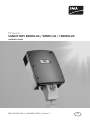
SUNNY BOY 8000TL-US / 9000TL-US / 10000TL-US
Installation Guide
SB8-10TL-IUS103811 | IMUS-SB8-10TLUS | Version 1.1
US
SMA America, LLC
Legal Restrictions
Copyright © 2010 SMA America, LLC. All rights reserved.
No part of this document may be reproduced, stored in a retrieval system, or transmitted, in any form
or by any means, electronic, mechanical, photographic, magnetic or otherwise, without the prior
written permission of SMA America, LLC.
SMA America, LLC makes no representations, express or implied, with respect to this documentation
or any of the equipment and/or software it may describe, including (with no limitation) any implied
warranties of utility, merchantability, or fitness for any particular purpose. All such warranties are
expressly disclaimed. Neither SMA America, LLC nor its distributors or dealers shall be liable for any
indirect, incidental, or consequential damages under any circumstances.
(The exclusion of implied warranties may not apply in all cases under some statutes, and thus the
above exclusion may not apply.)
Specifications are subject to change without notice. Every attempt has been made to make this
document complete, accurate and up-to-date. Readers are cautioned, however, that
SMA America, LLC reserves the right to make changes without notice and shall not be responsible for
any damages, including indirect, incidental or consequential damages, caused by reliance on the
material presented, including, but not limited to, omissions, typographical errors, arithmetical errors
or listing errors in the content material.
All trademarks are recognized even if these are not marked separately. Missing designations do not
mean that a product or brand is not a registered trademark.
The Bluetooth® word mark and logos are registered trademarks owned by Bluetooth SIG, Inc. and
any use of such marks by SMA America, LLC is under license.
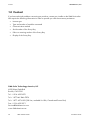
SMA America, LLC
3801 N. Havana Street
Denver, CO 80239 U.S.A.
Installation Guide
SB8-10TL-IUS103811
3
Important Safety Instructions
SMA America, LLC
IMPORTANT SAFETY INSTRUCTIONS
SAVE THESE INSTRUCTIONS
This manual contains important instructions for Sunny Boy US inverter, that must be followed during
installation and maintenance of the inverter.
The Sunny Boy is designed and tested according to international safety requirements, but as with all
electrical and electronic equipment, certain precautions must be observed when installing and/or
operating the Sunny Boy. To reduce the risk of personal injury and to ensure the safe installation and
operation of the Sunny Boy, you must carefully read and follow all instructions, cautions and warnings
in this installation manual.
Warnings in this document
A warning describes a hazard to equipment or personnel. It calls attention to a procedure or practice,
which, if not correctly performed or adhered to, could result in damage to or destruction of part or all
of the SMA equipment and/or other equipment connected to the SMA equipment or personal injury.
DANGER
DANGER indicates a hazardous situation which, if not avoided, will result in death or
serious injury.
WARNING
WARNING indicates a hazardous situation which, if not avoided, could result in death or
serious injury.
CAUTION
CAUTION indicates a hazardous situation which, if not avoided, could result in minor or
moderate injury.
NOTICE
NOTICE is used to address practices not related to personal injury.
4
SB8-10TL-IUS103811
Installation Guide
SMA America, LLC
Important Safety Instructions
Other symbols in this document
In addition to the safety and hazard symbols described on the previous pages, the following symbol
is also used in this installation manual:
Information
This symbol accompanies notes that call attention to supplementary information that you
must know and use to ensure optimal operation of the system.
Markings on this product
The following symbols are used as product markings with the following meanings.
Warning regarding dangerous voltage
The product works with high voltages. All work on the product must only be performed
as described in it‘s documentation.
Electric arc hazards
The product has large electrical potential differences between its conductors. Arc flashes
can occur through air when high-voltage current flows. Do not work on the product
during operation.
Beware of hot surface
The product can become hot during operation. Do not touch the product during
operation.
Observe the operating instructions
Read the product’s documentation before working on it. Follow all safety precautions
and instructions as described in the documentation.
AC current
DC current
Transformerless
Earth Ground
UL1741 is the standard applied by Underwriters Laboratories to the Sunny Boy to certify
that it meets the requirements of the National Electrical Code® and IEEE-929-2000.
IEEE 929-2000 provides recommendations regarding the proper equipment and
functionality necessary to ensure compatible operation when power generation is
connected to the utility grid.
Installation Guide
SB8-10TL-IUS103811
5
General Warnings
SMA America, LLC
General Warnings
General Warnings
All electrical installations must be done in accordance with all local electrical codes and
the National Electrical Code®, ANSI/NFPA 70. For installation in Canada the installations
must be done in accordance with applicable Canadian standards.
The Sunny Boy contains no user-serviceable parts except for the fans on the bottom of the
enclosure and the filters behind the fans as well as the handle covers on the sides of the
unit. For all repair and maintenance, always return the unit to an authorized SMA Service
Center.
Before installing or using the Sunny Boy, read all of the instructions, cautions, and warnings
on the Sunny Boy in this installation manual.
Before connecting the Sunny Boy to the electrical utility grid, contact the local utility
company. This connection must be made only by qualified personnel.
Wiring of the Sunny Boy must be made by qualified personnel only.
6
SB8-10TL-IUS103811
Installation Guide
SMA America, LLC
Table of Contents
Table of Contents
1
1.1
1.2
1.3
1.4
1.5
Notes on this manual. . . . . . . . . . . . . . . . . . . . . . . . . . . . . 11
Validity . . . . . . . . . . . . . . . . . . . . . . . . . . . . . . . . . . . . . . . . . . . 11
Target group . . . . . . . . . . . . . . . . . . . . . . . . . . . . . . . . . . . . . . . 11
Storage of the manuals. . . . . . . . . . . . . . . . . . . . . . . . . . . . . . . 11
Additional information . . . . . . . . . . . . . . . . . . . . . . . . . . . . . . . 11
Nomenclature . . . . . . . . . . . . . . . . . . . . . . . . . . . . . . . . . . . . . . 11
2
2.1
2.2
Safety . . . . . . . . . . . . . . . . . . . . . . . . . . . . . . . . . . . . . . . . . 12
Appropriate Usage . . . . . . . . . . . . . . . . . . . . . . . . . . . . . . . . . . 12
Safety instructions . . . . . . . . . . . . . . . . . . . . . . . . . . . . . . . . . . . 14
3
3.1
3.2
3.3
The Sunny Boy . . . . . . . . . . . . . . . . . . . . . . . . . . . . . . . . . . 15
Parts of the Sunny Boy . . . . . . . . . . . . . . . . . . . . . . . . . . . . . . . 15
Position of the Labels. . . . . . . . . . . . . . . . . . . . . . . . . . . . . . . . . 15
Identifying the Sunny Boy . . . . . . . . . . . . . . . . . . . . . . . . . . . . . 16
4
4.1
Unpacking and inspection. . . . . . . . . . . . . . . . . . . . . . . . . 17
Scope of delivery . . . . . . . . . . . . . . . . . . . . . . . . . . . . . . . . . . . 17
5
5.1
5.2
5.3
Mounting. . . . . . . . . . . . . . . . . . . . . . . . . . . . . . . . . . . . . . . 18
Safety . . . . . . . . . . . . . . . . . . . . . . . . . . . . . . . . . . . . . . . . . . . . 18
Selecting the mounting location . . . . . . . . . . . . . . . . . . . . . . . . 19
Mounting the Sunny Boy with the wall mounting bracket. . . . . 20
5.3.1
Possibilities for mounting the wall mounting bracket . . . . . . . . . . . . . . . . . . . 22
5.3.2
Mounting the wall mounting bracket. . . . . . . . . . . . . . . . . . . . . . . . . . . . . . . 23
5.4
5.5
Mounting the SMA DC Disconnect. . . . . . . . . . . . . . . . . . . . . . 25
Mounting the Sunny Boy onto the wall mounting bracket . . . . 26
6
6.1
Electrical Connection . . . . . . . . . . . . . . . . . . . . . . . . . . . . . 27
Safety . . . . . . . . . . . . . . . . . . . . . . . . . . . . . . . . . . . . . . . . . . . . 27
Installation Guide
SB8-10TL-IUS103811
7
Table of Contents
SMA America, LLC
6.2
6.3
6.4
6.5
Wiring Diagram with SMA DC Disconnect and Combiner Box 28
Insert the cable into the SMA DC Disconnect. . . . . . . . . . . . . . 29
Sunny Boy connection area overview. . . . . . . . . . . . . . . . . . . . 30
AC connection . . . . . . . . . . . . . . . . . . . . . . . . . . . . . . . . . . . . . 31
6.5.1
AC cable requirements . . . . . . . . . . . . . . . . . . . . . . . . . . . . . . . . . . . . . . . . . 32
6.5.2
Connect the AC cable in the DC Disconnect . . . . . . . . . . . . . . . . . . . . . . . . 34
6.5.3
Connecting the AC cable in the Sunny Boy . . . . . . . . . . . . . . . . . . . . . . . . . 35
6.6
DC connection . . . . . . . . . . . . . . . . . . . . . . . . . . . . . . . . . . . . . 37
6.6.1
DC connection requirements . . . . . . . . . . . . . . . . . . . . . . . . . . . . . . . . . . . . . 38
6.6.2
Connecting the DC cable . . . . . . . . . . . . . . . . . . . . . . . . . . . . . . . . . . . . . . . 38
6.7
Communication. . . . . . . . . . . . . . . . . . . . . . . . . . . . . . . . . . . . . 41
7
7.1
7.2
7.3
Commissioning . . . . . . . . . . . . . . . . . . . . . . . . . . . . . . . . . . 42
Display . . . . . . . . . . . . . . . . . . . . . . . . . . . . . . . . . . . . . . . . . . . 43
LED Display. . . . . . . . . . . . . . . . . . . . . . . . . . . . . . . . . . . . . . . . 45
Setting the display language . . . . . . . . . . . . . . . . . . . . . . . . . . 47
8
8.1
8.2
8.3
8.4
Opening and closing . . . . . . . . . . . . . . . . . . . . . . . . . . . . . 48
Opening the Sunny Boy . . . . . . . . . . . . . . . . . . . . . . . . . . . . . . 48
Closing the Sunny Boy . . . . . . . . . . . . . . . . . . . . . . . . . . . . . . . 49
Opening SMA DC Disconnect . . . . . . . . . . . . . . . . . . . . . . . . . 50
Closing SMA DC Disconnect . . . . . . . . . . . . . . . . . . . . . . . . . . 51
9
9.1
Maintenance. . . . . . . . . . . . . . . . . . . . . . . . . . . . . . . . . . . . 52
Checking heat dissipation. . . . . . . . . . . . . . . . . . . . . . . . . . . . . 52
9.1.1
Cleaning the fans . . . . . . . . . . . . . . . . . . . . . . . . . . . . . . . . . . . . . . . . . . . . . 52
9.1.2
Cleaning the handle covers . . . . . . . . . . . . . . . . . . . . . . . . . . . . . . . . . . . . . 53
9.2
Checking the DC Disconnect . . . . . . . . . . . . . . . . . . . . . . . . . . 53
9.2.1
Checking the fans . . . . . . . . . . . . . . . . . . . . . . . . . . . . . . . . . . . . . . . . . . . . . 54
10
10.1
Troubleshooting . . . . . . . . . . . . . . . . . . . . . . . . . . . . . . . . . 55
The red LED is on continuously . . . . . . . . . . . . . . . . . . . . . . . . . 55
8
SB8-10TL-IUS103811
Installation Guide
SMA America, LLC
Table of Contents
10.1.1
Inspecting and changing the varistors. . . . . . . . . . . . . . . . . . . . . . . . . . . . . . 57
11
11.1
11.2
11.3
11.4
Decommissioning . . . . . . . . . . . . . . . . . . . . . . . . . . . . . . . . 58
Disassembling the Sunny Boy and SMA DC Disconnect . . . . . 58
Packaging . . . . . . . . . . . . . . . . . . . . . . . . . . . . . . . . . . . . . . . . . 59
Storage . . . . . . . . . . . . . . . . . . . . . . . . . . . . . . . . . . . . . . . . . . . 59
Disposal . . . . . . . . . . . . . . . . . . . . . . . . . . . . . . . . . . . . . . . . . . 59
12
12.1
12.2
12.3
12.4
12.5
12.6
12.7
Technical data. . . . . . . . . . . . . . . . . . . . . . . . . . . . . . . . . . . 60
Sunny Boy 8000TL-US . . . . . . . . . . . . . . . . . . . . . . . . . . . . . . . 60
Sunny Boy 9000TL-US . . . . . . . . . . . . . . . . . . . . . . . . . . . . . . . 62
Sunny Boy 10000TL-US . . . . . . . . . . . . . . . . . . . . . . . . . . . . . . 64
SMA DC Disconnect. . . . . . . . . . . . . . . . . . . . . . . . . . . . . . . . . 66
FCC compliance information . . . . . . . . . . . . . . . . . . . . . . . . . . 67
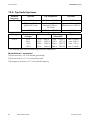
Trip limits/trip times. . . . . . . . . . . . . . . . . . . . . . . . . . . . . . . . . . 68
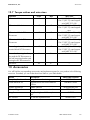
Torque values and wire sizes . . . . . . . . . . . . . . . . . . . . . . . . . . 69
13
Accessories . . . . . . . . . . . . . . . . . . . . . . . . . . . . . . . . . . . . . 69
14
Contact . . . . . . . . . . . . . . . . . . . . . . . . . . . . . . . . . . . . . . . . 70
Installation Guide
SB8-10TL-IUS103811
9
Table of Contents
10
SB8-10TL-IUS103811
SMA America, LLC
Installation Guide
SMA America, LLC
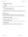
Notes on this manual
1 Notes on this manual
1.1 Validity
This manual describes the assembly, installation, commissioning and maintenance of the following
SMA inverters:
• Sunny Boy 8000TL-US (SB 8000TL-US-10)
• Sunny Boy 9000TL-US (SB 9000TL-US-10)
• Sunny Boy 10000TL-US (SB 10000TL-US-10)
This manual does not cover any details concerning equipment connected to the Sunny Boy (e. g. PV
modules). Information concerning the connected equipment is available from the manufacturer of the
equipment.
1.2 Target group
This manual is for qualified personnel. Qualified personnel have received training and have
demonstrated skills and knowledge in the construction and operation of this device. Qualified
personnel are trained to deal with the dangers and hazards involved in installing electric devices.
1.3 Storage of the manuals
Keep all Sunny Boy manuals in a convenient place for future reference.
1.4 Additional information
You will find further information on special topics in the download area at www.SMA-America.com.
1.5 Nomenclature
In this document SMA America Production, LLC is referred to in the following as SMA.
The syntax specified here for menus and parameters applies throughout the entire manual:
Installation Guide
SB8-10TL-IUS103811
11
Safety
SMA America, LLC
2 Safety
2.1 Appropriate Usage
The Sunny Boy is a PV inverter that converts DC current from PV generator into AC current. The Sunny
Boy is suitable for mounting indoors and outdoors.
You can use the AC current generated as follows:
House grid:
Energy flows into the house grid. The consumers connected, for example,
household devices or lighting, consume the energy. The energy left over is
fed into the public grid. When the Sunny Boy is not generating any energy,
e.g., at night, the consumers which are connected are supplied by the public
grid.
Public grid:
Stand-alone grid:
The Sunny Boy does not have its own energy meter. When energy is fed
into the public grid, the energy meter spins backwards.
Energy is fed directly into the public grid. The Sunny Boy is connected to a
separate energy meter. The energy produced is compensated at a rate
depending on the electric power company.
The Sunny Boy is connected to a stand-alone grid. A stand-alone grid is a
grid which is not connected to a public grid. The Sunny Boy needs a gridforming generator, for example, a Sunny Island, in order to function. The
energy generated is consumed directly on site, surplus energy can be
stored in batteries.
Policies vary from one utility company to another. Consult with a representative of the local
utility company before designing and installing a PV system.
Unbalanced load
The Sunny Boy inverters 8000TL-US, 9000TL-US and 10000TL-US generate a power exceeding
6 kVA. To prevent a situation of unbalanced loads between phases ensure that the inverters are
installed in sets of 3, connected to L1-L2, L1-L3, and L2-L3.
AC and DC disconnectors
Separate the Sunny Boy securely from the grid and the PV generators using AC and DC
disconnectors. You must provide an AC circuit breaker. The SMA DC Disconnect is included in the
delivery of the Sunny Boy and must be used for operating the inverter.
Grounding the PV modules
The Sunny Boy 8000TL-US, 9000TL-US and 10000TL-US is a transformerless inverter. That is why it
has no galvanic separation. Do not ground the DC circuits of the PV modules connected to the Sunny
Boy. Only ground the mounting frame of the PV modules.
If you connect grounded modules to the Sunny Boy, the error message F-Riso is displayed.
During operation, the DC circuit is connected to the AC grid.
12
SB8-10TL-IUS103811
Installation Guide
SMA America, LLC
Safety
Fuses
No string fuses are provided with the Sunny Boy or the SMA DC Disconnect.
In accordance to 2008 National Electrical Code® section 690.35 string fuses are required to protect
the installation from reverse currents.
String fuses can be installed in the SMA Sunny Boy Combiner Box. Refer to the appropriate manual
for detail information.
You can get more information about the Sunny Boy Combiner Box at www.SMA-America.com.
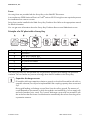
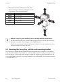
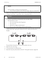
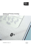
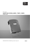
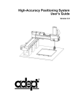
Principle of a PV plant with a Sunny Boy
Position
A
B
C
D
E
F
G
Description
PV modules
Sunny Boy Combiner Box
Sunny Boy with SMA DC Disconnect
AC load circuit breaker
Load
Energy meter
Utility grid
The Sunny Boy may only be operated with PV generators (modules and cabling) with protective
insulation. Do not connect any sources of energy other than PV modules to the Sunny Boy.
Capacitive discharge currents
PV modules with large capacities relative to ground, such as thin-film modules with cells on
a metallic substrate, are only to be implemented if their coupling capacity does not exceed
2 µF.
During grid feeding, a discharge current flows from the cells to ground. The amount of
current depends on the manner in which the modules are installed (e.g. foil on metal roof)
and on the weather (rain, snow). This "normal" discharge current may not exceed 50 mA
due to the fact that the inverter would otherwise automatically disconnect from the grid as
a protective measure.
Installation Guide
SB8-10TL-IUS103811
13
Safety
SMA America, LLC
PV plant design
When designing the PV plant, ensure that the values comply with the permitted operating range of all
components at all times. The free design programs "Solar Design Tools" (www.SMA-America.com)
will assist you. The manufacturer of the PV modules must have approved the modules for use with this
Sunny Boy device.
The Sunny Boy 8000TL-US, 9000TL-US and 10000TL-US is a transformerless inverter.
That is why it has no galvanic separation.
• The PV modules must be rated for at least the maximum PV system voltage.
Do not use the Sunny Boy for purposes other than those described here. Alternative uses,
modifications to the Sunny Boy or the installation of components not expressly recommended or sold
by the manufacturer void the warranty claims and operation permission.
2.2 Safety instructions
DANGER
During operation, high voltages are present in the Sunny Boy.
Death or serious injury due to electric shock.
• All work on the Sunny Boy must only be carried out by qualified personnel.
• Work on the Sunny Boy may only be carried out as described in this manual.
• Observe all safety instructions listed on the Sunny Boy, in this manual and of all
components of the PV plant.
WARNING
The Sunny Boy becomes hot during operation.
Risk of burn.
• Do not touch the enclosure during operation.
• Only touch the lid during operation.
14
SB8-10TL-IUS103811
Installation Guide
SMA America, LLC
The Sunny Boy
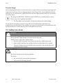
3 The Sunny Boy
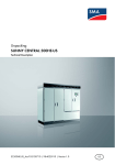
3.1 Parts of the Sunny Boy
Position
A
B
C
Description
Ergonomic handles
Display
Fans
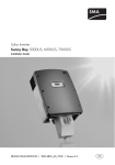
3.2 Position of the Labels
Position
A
B
C
Installation Guide
Description
Type label
General warning label
Warning label DC connection
SB8-10TL-IUS103811
15
The Sunny Boy
SMA America, LLC
3.3 Identifying the Sunny Boy
You can identify the Sunny Boy by the type label. It is on the right side of the enclosure.
The type label shows:
• The serial number (Serial No.).
• The type of product (Type/Model).
• Device-specific characteristics.
16
SB8-10TL-IUS103811
Installation Guide
SMA America, LLC
Unpacking and inspection
4 Unpacking and inspection
All Sunny Boy inverters are checked before shipping and packaged in sturdy boxes. However the
sturdy boxes do not guarantee that damage will not occur during shipping and delivery.
It is important to carefully inspect the shipping box and contents prior to installation. If you detect any
external damage after unpacking, report the damage immediately to your SMA dealer and to the
shipping company that delivered the unit. If it becomes necessary to return the Sunny Boy, use the
original packing material.
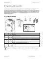
4.1 Scope of delivery
Position
A
B
C
D
E
F
G
Number
1
1
1
2
2
2
1
1
2
Description
Sunny Boy
Wall-mounting bracket
Spare screw and spare washer for closing the Sunny Boy lid
Screws and washers for fastening the Sunny Boy to the wall-mounting bracket
Spare jumpers for fan test
Handle covers (left and right)
SMA DC Disconnect (type DC-DisconTL-US-10)
Screw and washer for closing the DC Disconnect lid
Screws and washers for fastening the DC Disconnect to the wall-mounting
bracket
If not ordered differently, the SMA Sunny Boy Combiner Box is included in the scope of
delivery as a standard feature. Refer to the appropiate manual for detail information.
Installation Guide
SB8-10TL-IUS103811
17
Mounting
SMA America, LLC
5 Mounting
5.1 Safety
DANGER
Danger to life due to fire or explosions.
There is always a certain risk with electric devices that a fire can occur, even though
greatest attention was paid to avoiding this during the development.
Do not install the inverter:
• on flammable construction materials,
• in areas where highly flammable materials are stored,
• in potentially explosive areas.
WARNING
The Sunny Boy becomes hot during operation.
Burn injuries will occur when touching the enclosure.
• Mount the Sunny Boy in such a way that it cannot be touched inadvertently.
CAUTION
Falling of the Sunny Boy may cause injuries.
Crushing of body parts will result.
• Take the weight of the Sunny Boy of approximately 77 lbs. (35 kg) into account
when mounting.
18
SB8-10TL-IUS103811
Installation Guide
SMA America, LLC
Mounting
5.2 Selecting the mounting location
Observe the following conditions during installation:
• The installation method and mounting location must be suitable for the weight and dimensions
of the Sunny Boy (see section 12 ”Technical data” (page 60)).
• Take the dimensions of the DC Disconnect into account (Page 25).
• Mount on a solid surface.
• The mounting location must be accessible at all times.
• Vertical installation or tilted backwards by max. 15°.
• The connection area must point downwards.
• Never install the device with a forward tilt.
• Do not install horizontally.
• Install at eye level to allow operating status to be read at all times.
• The ambient temperature must be below 113 °F (45 °C) to ensure optimal operation.
• Do not expose the Sunny Boy to direct sunlight, in order to avoid power reduction due to
excessive heating.
• In a living area, do not mount the unit on
plasterboard walls (or similar) in order to avoid
audible vibrations.
The Sunny Boy can emit noises when in use which
can be regarded as a nuisance.
Installation Guide
SB8-10TL-IUS103811
19
Mounting
SMA America, LLC
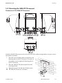
• Observe the minimum clearances to walls, other
devices or objects as shown in the diagram in order
to guarantee sufficient heat dissipation.
Position
Above
Below
Left
Right
Front
Clearance
12 in. (30 cm)
36 in. (90 cm)
12 in. (30 cm)
12 in. (30 cm)
2 in. (5 cm)
Multiple Sunny Boy units installed in areas with high ambient temperatures
The individual Sunny Boy units must be far enough apart to ensure that the individual Sunny
Boy units do not take in the cooling air of the neighboring unit.
If necessary, increase the clearances and make sure there is enough ventilation to ensure
sufficient cooling of the Sunny Boy units.
5.3 Mounting the Sunny Boy with the wall mounting bracket
The Sunny Boy is shipped with a T-shaped wall-mounting bracket that is suitable for use with most
walls. The horizontal part of the bracket has 12 holes. Make sure that the wall you choose to mount
the Sunny Boy on is plumb and sturdy enough to support the weight over a long period of time. Be
sure to use the appropriate type of mounting hardware for the wall material. Ensure that the hardware
is no smaller than ¼ in.
20
SB8-10TL-IUS103811
Installation Guide
SMA America, LLC
Mounting
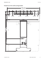
Dimensions of the wall mounting bracket
Installation Guide
SB8-10TL-IUS103811
21
Mounting
SMA America, LLC
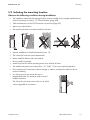
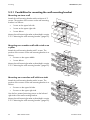
5.3.1 Possibilities for mounting the wall mounting bracket
Mounting on stone wall
Attach the wall mounting bracket with a minimum of 3
screws. The position of the screws on the wall mounting
bracket is as follows:
• 1 screw on the upper left side.
• 1 screw on the upper right side.
• 1 screw below.
Mount the wall mounting bracket as described in section
5.3.2 ”Mounting the wall mounting bracket” (page 23).
Mounting on a wooden wall with a stud or on
a pillar
Attach the wall mounting bracket with 3 screws. The
position of the screws on the wall mounting bracket is as
follows:
• 2 screws on the upper middle.
• 1 screw below.
Mount the wall mounting bracket as described in section
5.3.2 ”Mounting the wall mounting bracket” (page 23).
Mounting on a wooden wall with two studs
Attach the wall mounting bracket with 4 screws. The
position of the screws on the wall mounting bracket is as
follows:
• 2 screws on the upper left side.
• 2 screws on the upper right side.
Use the four external mounting screws on the left and
right sides of the wall mounting bracket.
Mount the wall mounting bracket as described in section
5.3.2 ”Mounting the wall mounting bracket” (page 23).
22
SB8-10TL-IUS103811
Installation Guide
SMA America, LLC
Mounting
5.3.2 Mounting the wall mounting bracket
1. Position the wall-mounting bracket against the wall where you intend to mount the Sunny Boy.
Try to mount the Sunny Boy with the display at eye-level.
2. Place a level on the top edge of the bracket. Adjust the position until it is leveled. The bottom of
the bracket will be the approximate location of the bottom of the inverter.
DANGER
Risk of electric shock by drilling into power cables.
Death or serious injuries will result.
• Before drilling, check installation location for power cables.
CAUTION
Falling of the Sunny Boy may cause injuries.
Crushing of body parts will result.
• Ensure that there are studs in the wall where you intend to drill holes.
3. Use the wall-mounting bracket as a template. Mark the wall through at least three holes in
horizontal or vertical position of the bracket (see chapter 5.3.1 ”Possibilities for mounting the
wall mounting bracket” (page 22)).
4. Remove the bracket and drill holes at the marks.
5. Insert wall anchors into the drill holes.
CAUTION
Falling of the Sunny Boy may cause injuries.
Crushing of body parts will result.
• Do not use molly or toggle bolts to mount the Sunny Boy to sheet rock or panelling.
Installation Guide
SB8-10TL-IUS103811
23
Mounting
SMA America, LLC
Tip for installing
The diameter of the holes you drill must match the hardware you are using to mount the
Sunny Boy.
For example, if you are mounting the Sunny Boy to a concrete wall, the hole diameter
should be approximately the same as the outside diameter of the concrete anchors you
intend to use. If you are mounting the Sunny Boy on a wall that has wooden studs inside it,
the hole diameter must be the correct size for the lag screws you intend to use to mount the
bracket. It is recommended that the lag screws be made of stainless steel, and the diameter
of the screws closely match the diameter of the holes in the wall-mounting bracket. Make
sure that the screws are long enough to penetrate the wall to a depth of 11⁄2 in.
6. Insert the screws through the holes in the wall mounting bracket and into the drill holes.
7. Tighten the screws clockwise until the bracket is held firmly against the wall. Do not overtighten
the screws.
☑ The wall mounting bracket is mounted.
24
SB8-10TL-IUS103811
Installation Guide
SMA America, LLC
Mounting
5.4 Mounting the SMA DC Disconnect
Dimensions of the SMA DC Disconnect
Attach the SMA DC Disconnect to the two lower holes of the wall-mounting bracket, using two screws
and washers provided.
1. Place the screws and the washers in the holes in the
fastening tabs on the DC Disconnect. The teeth on
the washers must lie against the fastening tabs of
the DC Disconnect.
2. Place the SMA DC Disconnect against the wall
mounting bracket.
3. Tighten the screws with 44 in-lbs (5 Nm) torque.
☑ The SMA DC Disconnect is mounted.
Installation Guide
SB8-10TL-IUS103811
25
Mounting
SMA America, LLC
5.5 Mounting the Sunny Boy onto the wall mounting bracket
CAUTION
Falling of the Sunny Boy may cause injuries. Crushing of body parts will resullt.
• Take the weight of the Sunny Boy into account when mounting.
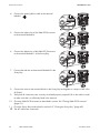
1. Remove the handle covers on the right and left side of the Sunny Boy.
2. Transport the Sunny Boy between two persons, using the side handles above and below.
or
Put a steel bar with a maximum diameter of 11⁄8 in (30 mm) through the enclosure opening
above and transport it between two people.
3. Hook the Sunny Boy using the enclosure opening in
the back plate into the wall bracket.
4. Inspect the Sunny Boy from both sides to ensure that
it sits centered on the wall bracket.
5. Screw the Sunny Boy onto the wall mounting bracket
on both sides using the screws provided.
6. Tighten the screws clockwise with a torque of
44 in‑lbs. (5 Nm).
7. Check that the unit is securely in place.
8. Put the handle covers over the handles.
The air grills are marked "rechts/right" and
"links/left" on the interior for proper assignment.
The air grills prevent dirt and insects from entering
the device and if necessary, can be reordered from
SMA America 13 ”Accessories” (page 70).
☑ The Sunny Boy is mounted.
26
SB8-10TL-IUS103811
Installation Guide
SMA America, LLC
Electrical Connection
6 Electrical Connection
6.1 Safety
NOTICE
Ingress of water when mounting and installing the Sunny Boy.
Damage to the Sunny Boy will result.
• Do not open the Sunny Boy when it is raining or when high humidity is present
(> 95 %).
NOTICE
Touching the components can result in electrostatic discharges.
Damage to components will result.
• Ground yourself before touching a component.
Electrical installations
All electrical installations must be done in accordance with all local electrical codes and
the National Electrical Code®, ANSI/NFPA 70. For installation in Canada the installations
must be done in accordance with applicable Canadian standards.
AC grounding
The Sunny Boy must be connected to the AC ground from the utility via the Ground Terminal (PE) (see
6.4 ”Sunny Boy connection area overview” (page 30)).
PV grounding
The PV array (frame) ground must be connected to the grounding electrode terminal (see 6.4 ”Sunny
Boy connection area overview” (page 30)). The size for the conductor is usually based on the size of
the largest conductor in the DC system.
DC grounding electrode conductor
A DC grounding electrode conductor may be required by the Authority Having Jurisdiction (AHJ). Use
the PV grounding and DC grounding electrode conductor terminal (see 6.4 ”Sunny Boy connection
area overview” (page 30)).
Installation Guide
SB8-10TL-IUS103811
27
Electrical Connection
SMA America, LLC
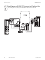
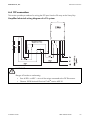
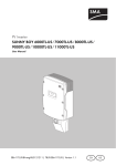
6.2 Wiring Diagram with SMA DC Disconnect and Combiner Box
For operating the Sunny Boy the provided SMA DC Disconnect must be used.
28
SB8-10TL-IUS103811
Installation Guide
SMA America, LLC
Electrical Connection
6.3 Insert the cable into the SMA DC Disconnect
NOTICE
Ingress of water when mounting and installing the Sunny Boy.
Damage to the Sunny Boy will result.
• For conduit hubs, use only UL Listed rainproof, or wet location hubs complying with
UL 514B for entry into the enclosure.
Inserting the cable into the SMA DC Disconnect
1. Open the SMA DC Disconnect (see chapter 8.3 ”Opening SMA DC Disconnect” (page 50)).
2. Break out the knockouts for the AC and DC cables. Use separate cable conduits for the AC and
the DC cables.
NOTICE
Damage to the SMA DC Disconnect due to enlargement of the knockout holes.
• Do not enlarge the knockout holes. The knockout holes are intended for the
installation of inflexible cable conduits of a size of up to 1 in. (25.4 mm).
3. Insert the cable conduit fittings into the knockout holes.
4. Pull the cable conduits into the fittings and tighten them.
DANGER
High voltages are present on the AC and DC cables.
Death or serious injuries due to touching the voltage-conducting cables.
5. Turn off the main switch in the switch cabinet.
6. Cover the PV modules with opaque material.
7. Pull the AC and DC cables through the cable conduits into the SMA DC Disconnect.
☑ The cables are inserted into the SMA DC Disconnect.
Installation Guide
SB8-10TL-IUS103811
29
Electrical Connection
SMA America, LLC
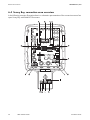
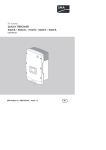
6.4 Sunny Boy connection area overview
In the following overview illustration there is a schematic representation of the connection area of an
open Sunny Boy with SMA DC Disconnect.
30
SB8-10TL-IUS103811
Installation Guide
SMA America, LLC
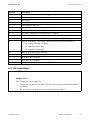
Position
A
B
C
D
E
F
G
H
I
K
L
Electrical Connection
Description
Socket for optional communication Piggy-Back (RS485 or wireless)
Display
Status LEDs
Jumper position for verifiying the operation of the fans
Power Balancer terminal
Flat connection for grounding the cable shield for communication
Sunny Boy: Ground terminal (PE)
Sunny Boy: Output AC line terminals (N, L1 and L2)
Varistor terminal with varistors
SMA DC Disconnect: Output AC line terminals (N, L1 and L2)
SMA DC Disconnect: Grounding electrode terminal for the connection of:
• Grounding electrode conductor
• DC equipment grounding
• AC equipment grounding
SMA DC Disconnect: DC+ terminal
SMA DC Disconnect: DC − terminal
Sunny Boy: DC − terminal
Sunny Boy: DC+ terminal
Terminal for optional communication (RS485)
M
N
O
P
Q
6.5 AC connection
NOTICE
Danger of fire
Overvoltage may cause cable fire.
• Overcurrent protection for the AC output circuit must be provided in the electrical
installation.
• The size of the overcurrent protection must be maximum 60 A.
Installation Guide
SB8-10TL-IUS103811
31
Electrical Connection
SMA America, LLC
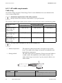
6.5.1 AC cable requirements
Cable sizing
Use the free design programs "Solar Design Tools" at www.SMA-America.com to determine the
correct string configuration.
Connection requirements of the utility operator
Always observe the connection requirements of your grid operator.
The maximum cable lengths relative to the conductor cross-section are shown in the following table.
Conductor crosssection
2 AWG (35 mm²),
194 °F (90 °C)
copper cable
4 AWG (25 mm²),
194 °F (90 °C)
copper cable
6 AWG, (16 mm²),
194 °F (90 °C)
copper cable
SB 8000TL-US
184 ft (56 m)
Maximum cable length
SB 9000TL-US
164 ft (50 m)
SB 10000TL-US
148 ft (45 m)
115 ft (35 m)
103 ft (31 m)
92 ft (28 m)
72 ft (22 m)
65 ft (20 m)
58 ft (18 m)
Use only solid or stranded wire but not fine stranded wire.
• Ambient temperature
• Routing method
Position
A
B
32
The higher the ambient temperature, the higher are the power
losses. Use cables with a large cross-section at installations with
high ambient temperatures.
The cables heat up during operation. If there are several cables in
a cable conduit, the temperature of all cables increases. Use
cables with a large cross-section if you lay several cables in one
cable conduit.
Name
Coductor cross-section
Strip insulation
SB8-10TL-IUS103811
Value
6 … 2 AWG (16 … 35 mm²)
3⁄ in. (18 mm)
4
Installation Guide
SMA America, LLC
Electrical Connection
Load disconnection unit
You must install a separate line circuit breaker for each inverter in order to ensure that the inverter can
be securely disconnected under load. See the technical data for the maximal permissible rating
Page 60).
DANGER
Risk of fire due to improper wiring.
Death or serious burn injuries will result.
When more than one inverter is connected to the same line circuit breaker, the protective
function of the line circuit breaker is no longer guaranteed.
• Do not connect more than 1 inverter to each line circuit breaker.
• When selecting the circuit breaker comply with the maximum permissible fuse
protection of the inverter.
DANGER
Risk of fire due to overcurrent.
Death or serious burn injuries will result.
When a Sunny Boy and a consumer are
connected to the same line circuit breaker, the
protective function of the line circuit breaker is
no longer guaranteed. The current from the
Sunny Boy and the grid can add up to
overcurrent which is not detected by the line circuit breaker.
• Do not connect loads between the Sunny Boy and the line circuit breaker without
protection.
• Always install separate fuses for loads.
NOTICE
Damage to the Sunny Boy by using screw type fuse elements as a load disconnection unit.
A screw type fuse element is not a load disconnection device, and thus must not be used
as a load disconnection unit. A screw type fuse element is only used as cable protection.
When disconnecting under load using a screw type fuse element, the Sunny Boy can be
damaged.
• Only use a load disconnecting switch or a line circuit breaker as a load
disconnecting unit.
Installation Guide
SB8-10TL-IUS103811
33
Electrical Connection
SMA America, LLC
6.5.2 Connect the AC cable in the DC Disconnect
1. Open all AC and DC circuit breakers or load-disconnecting switches.
2. Open the main fuse in the fuse box.
3. Remove the screws on the fuse box cover.
4. Remove the fuse box cover toward the front.
5. Ensure that there is no voltage between the fuse output and the ground bar. Use a multimeter.
The voltage must be 0 V.
6. Break out a 1 in. (25.4 mm) knockout from the underside of the fuse box.
7. Lay a cable conduit from the fuse box to the DC Disconnect (see chapter 6.3 ”Insert the cable
into the SMA DC Disconnect” (page 29)).
8. Place the cover back onto the fuse box.
9. Tighten the screws.
10. Open the DC Disconnect as described in section 8.3 ”Opening SMA DC Disconnect”
(page 50).
11. Lead the AC cable through the cable conduit from the inside of the fuse box into the inside of
the DC Disconnect.
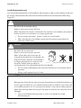
CAUTION
Ground faults, unreliable and resistive connections due to faulty wire nuts.
• Avoid using wire nuts to join any wires together or to make any connections
anywhere in the PV system.
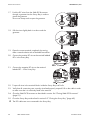
12. Open the screw terminals completely by turning the screws counterclockwise with a flat-head
screwdriver.
13. Connect the AC equipment-ground wire (A) to the PE
terminal labeled
in the SMA DC Disconnect.
14. Connect the L1 (AC line 1) wire to the terminal
labeled L1 in the SMA DC Disconnect.
34
SB8-10TL-IUS103811
Installation Guide
SMA America, LLC
Electrical Connection
15. Connect the L2 (AC line 2) wire to the terminal
labeled L2 in the SMA DC Disconnect.
16. Connect the N (AC line N) wire to the terminal
labeled N in the SMA DC Disconnect.
17. Connect the wires to the terminal blocks in the SMA DC Disconnect and tighten to a torque
of 40 in‑lbs. (4.5 Nm).
18. Verify that all connections are correctly wired and properly torqued. Pull on the cable in order
to make sure that it is sufficiently fixed in the terminal.
☑ The AC cables are now connected in the SMA DC Disconnect.
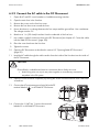
6.5.3 Connecting the AC cable in the Sunny Boy
1. Open the Sunny Boy as described in section 8.1 ”Opening the Sunny Boy” (page 48).
2. Push the cable through a grommet into the Sunny
Boy in order to pierce the grommet.
Do not use sharp tools to open the grommet.
3. Pull the cable slightly back in order to seal the
grommet.
Installation Guide
SB8-10TL-IUS103811
35
Electrical Connection
SMA America, LLC
4. Connect the green/yellow cable to the terminal
labeled:
5. Connect the white wire of the SMA DC Disconnect
to the terminal labeled N.
6. Connect the black wire of the SMA DC Disconnect
to the terminal labeled L1 of the Sunny Boy.
7. Connect the red wire to the terminal labeled L2 in the
Sunny Boy.
8. Connect the wires to the terminal blocks in the Sunny Boy and tighten to a torque of 40 in‑lbs.
(4.5 Nm).
9. Verify that all connections are correctly wired and properly torqued. Pull on the cable in order
to make sure that it is sufficiently fixed in the terminal.
10. Close the SMA DC Disconnect as described in section 8.4 ”Closing SMA DC Disconnect”
(page 51).
11. Close the Sunny Boy as described in section 8.2 ”Closing the Sunny Boy” (page 49).
☑ The AC cables are connected.
36
SB8-10TL-IUS103811
Installation Guide
SMA America, LLC
Electrical Connection
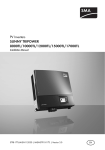
6.6 DC connection
This section provides procedures for wiring the DC input from the PV array to the Sunny Boy.
Simplified electrical wiring diagram of a PV system
WARNING
Danger of fire due to overheating.
• Fuse all DC+ und DC − wires of the strings connected to the DC Disconnect.
• Observe 2008 National Electrical Code® section 690.35.
Installation Guide
SB8-10TL-IUS103811
37
Electrical Connection
SMA America, LLC
6.6.1 DC connection requirements
Cable sizing
All electrical installations must be done in accordance with all local electrical codes and with the
National Electrical Code®, ANSI/NFPA 70. For installation in Canada the installations must be done
in accordance with applicable Canadian standards.
When selecting the type and cross-section of the cable in accordance with the routing method,
observe the following requirements:
• For all DC wiring connections to the string combiner box use 10 … 6 AWG (6 … 16 mm²),
194 °F (90 °C) rated copper wire (National Electrical Code® 690.35).
• For DC wiring connection between the string combiner box and the inverter use min. 8 AWG
(10 mm²), 194 °F (90 °C) rated copper wire (National Electrical Code® 310.16).
• Use only solid or stranded wire but not fine stranded wire.
Use the free design programs "Solar Design Tools" at www.SMA-America.com to
determine the correct string configuration.
6.6.2 Connecting the DC cable
DANGER
High voltage is present inside the DC cables.
Death or serious injury will result when damaging a DC cable or touching a DC conductor.
• You have to connect the DC cables from the PV array to the Sunny Boy in the order
described in this manual.
1. Lay a cable conduit from the Sunny Boy Combiner Box to the SMA DC Disconnect (see chapter
6.3 ”Insert the cable into the SMA DC Disconnect” (page 29)).
DANGER
High voltage is present in PV modules exposed to light.
Death due to electric shock when touching a DC conductor.
• During installation, cover the PV modules with opaque material.
2. Follow all safety instructions of the PV module manufacturer.
3. Open the SMA DC Disconnect as described in section 8.3 ”Opening SMA DC Disconnect”
(page 50).
4. Lead the AC cable through the cable conduit into the inside of the SMA DC Disconnect.
38
SB8-10TL-IUS103811
Installation Guide
SMA America, LLC
Electrical Connection
CAUTION
Ground faults, unreliable and resistive connections due to faulty wire nuts.
• Avoid using wire nuts to join any wires together or to make any connections
anywhere in the PV system.
5. Open the screw terminals completely by turning the screws counterclockwise with a flat-head
screwdriver.
6. Connect the grounding electrode conductor to the
grounding electrode conductor terminal (B).
7. Optional: Connect the PV frame grounding to the
grounding electrode conductor terminal (A).
8. Tighten the screw terminals clockwise with a torque
of 40 in‑lbs. (4.5 Nm).
9. Verify that all connections are correctly wired and
properly torqued. Pull on the cable in order to make
sure that it is sufficiently fixed in the terminal.
☑ The DC cables are now connected in the SMA DC Disconnect.
10. Check the connection cables of the PV modules for
correct polarity and to make sure that the maximum
input voltage of the Sunny Boy is not exceeded.
11. Open the screw terminals completely by turning the
screws counterclockwise with a flat-head
screwdriver.
12. Connect the negative DC wires (A) to the terminal
labeled – in the SMA DC Disconnect.
13. Connect the positive DC wires (A) to the terminal
labeled + in the SMA DC Disconnect.
14. Torque all wires in the terminal blocks inside the SMA DC Disconnect to 40 in-lbs. (4.5 Nm).
15. Verify that all connections are correctly wired and properly torqued. Pull on the cable in order
to make sure that it is sufficiently fixed in the terminal.
☑ The DC cables are now connected to the SMA DC Disconnect.
16. Open the Sunny Boy as described in section 8.1 ”Opening the Sunny Boy” (page 48).
Installation Guide
SB8-10TL-IUS103811
39
Electrical Connection
SMA America, LLC
17. Push the DC wires from the SMA DC disconnect
through a grommet into the Sunny Boy in order to
pierce the grommet.
Do not use sharp tools to open the grommet.
18. Pull the wires slightly back in order to seal the
grommet.
19. Open the screw terminals completely by turning
them counterclockwise with a flat-head screwdriver.
20. Connect the positive DC wire to the terminal labeled
DC+ in the Sunny Boy.
21. Connect the negative DC wire to the terminal
labeled DC − in the Sunny Boy.
22. Torque all wires in the terminal blocks inside the Sunny Boy to 40 in-lb.
23. Verify that all connections are correctly wired and properly torqued. Pull on the cable in order
to make sure that it is sufficiently fixed in the terminal.
24. Close the SMA DC Disconnect as described in section 8.4 ”Closing SMA DC Disconnect”
(page 51).
25. Close the Sunny Boy as described in section 8.2 ”Closing the Sunny Boy” (page 49).
☑ The DC cables are now connected in the Sunny Boy.
40
SB8-10TL-IUS103811
Installation Guide
SMA America, LLC
Electrical Connection
6.7 Communication
The Sunny Boy can be equipped with a communication interface (socket see section 6.4 ”Sunny Boy
connection area overview” (page 30)) to communicate with special data acquisition devices (e.g.
Sunny WebBox) or a PC with appropriate software (e.g. Sunny Data).
For a complete listing of all applicable communication options refer to the SMA web page or the
product catalogue.
See the communication interface documentation for a detailed wiring diagram and instructions for
insertion.
Installation Guide
SB8-10TL-IUS103811
41
Commissioning
SMA America, LLC
7 Commissioning
All Sunny Boy inverters have a sophisticated system for detecting and responding to PV array ground
faults as required by National Electrical Code® section 690.35 (C). The ground fault protection
device is active whenever there is sufficient DC voltage to turn on the LCD in the Sunny Boy.
Check the following requirements before commissioning:
• AC cable correctly connected
• DC cable correctly connected
• securely fastened enclosure lid
• The line circuit breaker is laid out correctly, if used.
Commission the Sunny Boy
DANGER
High voltage is present inside the PV power plant.
Death or serious injury will result when damaging a DC cable or touching a DC conductor.
• Commission the Sunny Boy in the order described in the following procedure.
1. Make sure any covering placed over the PV array is removed.
2. Connect the grid voltage to the Sunny Boy by switching on the main AC circuit breaker in the
main utility panel.
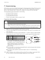
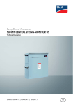
3. Switch the SMA DC Disconnect to position labeled as ”1”. If there is sufficient sunlight available,
the Sunny Boy will enter the “Wait” mode at this time and the green LED will begin to blink.
A Green LED Operation
B Red LED
Ground fault
C Yellow LED Disturbance
☑ If no AC faults are detected, the ”Wait” mode
will end after 10 seconds and the green LED will
stop blinking, remain on and the Sunny Boy will
begin to operate normally. If an AC fault is
registered, the Sunny Boy will wait 5 minutes
prior to starting.
☑ If the Sunny Boy is not operating as expected after the commissioning procedure has been
completed, refer to the user manual.
☑ The meaning of the red LED is described in detail in section 10 ”Troubleshooting”
(page 55).
☑ If there is adequate solar irradiation and the resulting PV input voltage is greater than 360 V
DC, the Sunny Boy will automatically begin feeding power to the utility grid.
42
SB8-10TL-IUS103811
Installation Guide
SMA America, LLC
Commissioning
7.1 Display
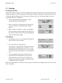
Feeding operation
After fault-free grid connection of the Sunny Boy it takes approximately one minute until the following
display messages are shown alternately. The display messages shown before only have the purpose
of indicating the initialization of the Sunny Boy and the process of controlling whether the power
supply requirements are fulfilled.
• The energy generated today and the current
operating mode are displayed first.
• After 5 seconds or by tapping on the housing lid,
the current feed-in output and the PV voltage
appear.
• After a further 5 seconds, or when you tap again,
the total energy produced and the time the Sunny
Boy has been connected to the grid are displayed.
• Then the cycle begins again.
Disturbance
• If a disturbance occurs, the message "Disturbance"
will be shown in the status bar.
E-today
0Wh
Mode Disturbance
• The exact failure message follows.
For example, if the grid fault message shown here
is displayed immediately after connection, it may
be due to the fact that the AC wire is not correctly
connected or the circuit breaker is not switched on
yet.
• If a non-standard compliant measured value is
responsible for the disturbance, then the value
measured at the time of the fault is displayed. If
another measurement is possible, the present value
is displayed in the second line.
Refer to the delivered user manual of the Sunny Boy to read the exact explanations for the error and
status messages!
Installation Guide
SB8-10TL-IUS103811
43
Commissioning
SMA America, LLC
PV overvoltage
!PV-Overvoltage!
!DISCONNECT DC!
NOTICE
Excessive DC voltage can destroy the Sunny Boy.
• Open all AC and DC circuit breakers or load-disconnecting switches.
Check DC voltage:
• Greater than 600 V: Contact the planner/installer of the PV generator for assistance.
• Lower than 600 V: Reconnect the Sunny Boy to the PV generator as described in section
6.6 ”DC connection” (page 37).
• If the message occurs again, disconnect the Sunny boy again and contact SMA (see section
14 ”Contact” (page 71)).
44
SB8-10TL-IUS103811
Installation Guide
SMA America, LLC
Commissioning
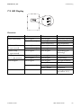
7.2 LED Display
Overview
Green
Glows continuously
Red
Does not glow
Glows continuously
Flashes quickly
(3 x per second)
Flashes slowly
(1 x per second)
Briefly goes out
(ca. 1 x per second)
Does not glow
Does not glow
Glows continuously
Yellow
Does not glow
Does not glow
Glows continuously
Does not glow
Does not glow
Status
OK (feeding operation)
Disturbance
OK (initialization)
OK (stop)
Disturbance
Does not glow
Does not glow
OK (waiting, grid
monitoring)
Glows continuously
Does not glow
Does not glow
Does not glow
Disturbance
OK (derating)
Does not glow
Does not glow
Glows / flashes
Does not glow
Glows / flashes
Not relevant
OK (night shutdown)
Disturbance
Disturbance
Disturbance
Warning
(see section 10.1)
Glows continuously
Not relevant
Installation Guide
Flashes
SB8-10TL-IUS103811
45
Commissioning
SMA America, LLC
Feeding operation
After a fault-free grid connection of the Sunny Boy, it takes approximately one minute until the green
LED is continuously on. The blink codes shown before only have the purpose of indicating the
initialization of the Sunny Boy and the process of checking whether the power supply requirements
are fulfilled.
Disturbance or fault
If the Sunny Boy detects a disturbance or error, this is indicated through a blink code of the yellow
and, where applicable, the red LEDs.
For example, if the yellow LED glows for 5 seconds immediately after connection, then goes out for
3 seconds and then flashes briefly twice, there is a grid fault. This could be because the AC cable has
not been connected correctly or the line circuit breaker has not yet been switched on.
Explanation of the blink codes
For a detailed description of the blink codes, see the provided Sunny Boy user manual.
46
SB8-10TL-IUS103811
Installation Guide
SMA America, LLC
Commissioning
PV overvoltage
(Yellow LED flashes 4 times quickly in succession)
NOTICE
Excessive DC voltage can destroy the Sunny Boy.
• Open all AC and DC circuit breakers or load-disconnecting switches.
Check DC voltage:
• Greater than 600 V: Contact the planner/installer of the PV generator for assistance.
• Lower than 600 V: Reconnect the Sunny Boy to the PV generator as described in section
6.6 ”DC connection” (page 37).
If the message occurs again, disconnect the Sunny boy again and contact SMA America (see section
14 ”Contact” (page 71)).
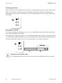
7.3 Setting the display language
You can set the language of the display using the switches on the underside of the display assemblies
inside the Sunny Boy.
Proceed as follows:
1. Open the Sunny Boy as described in section 8.1 ”Opening the Sunny Boy” (page 48).
2. Set the switches for the required language, as shown below.
Language
German
English
French
Spanish
Switch S2
B
B
A
A
Switch S1
B
A
B
A
3. Close the Sunny Boy as described in section
8.2 ”Closing the Sunny Boy” (page 49).
☑ The display language is set.
Installation Guide
SB8-10TL-IUS103811
47
Opening and closing
SMA America, LLC
8 Opening and closing
NOTICE
Electrostatic discharges.
Internal components of the Sunny Boy can be irreparably damaged by electrostatic
discharge.
• Ground yourself before you touch a component.
8.1 Opening the Sunny Boy
DANGER
During operation, high voltages are present in the Sunny Boy.
Death or serious injury due to electric shock.
• Open the Sunny Boy in the order described in the following procedure.
1. Disconnect all AC and DC circuit breakers or load-disconnecting switches. Ensure they cannot
reconnect accidentally.
2. Wait alt least for 5 minutes for any residual voltages to dissipate.
3. Remove the six screws and lock washers from the enclosure lid. Pull the lid forward smoothly.
4. Place the lid, screws, and washers aside. They will be out of your way while you are connecting
wires and cables to the Sunny Boy.
NOTICE
Ingress of water into the open Sunny Boy.
Damage to the Sunny Boy will result.
• Do not open the Sunny Boy when it is raining or when high humidity is present
(> 95 %).
• Be careful not to misplace the screws or the washers. All six screws and lock washers
are required to ensure that the lid is grounded properly and is fully sealed to the case.
• Handle the lid carefully. Even minor damage to the lid could result in an inadequate
seal between the lid and the enclosure, thus allowing moisture to enter the case and
damage the sensitive electronic components.
☑ The Sunny Boy is open.
48
SB8-10TL-IUS103811
Installation Guide
SMA America, LLC
Opening and closing
8.2 Closing the Sunny Boy
1. Check wire routing to ensure that no wires can interfere with proper sealing of the lid and that
no pressure will be exerted on the connections when the lid is replaced.
2. Locate the six screws and lock washers you removed to take the lid off the Sunny Boy. Make
sure you have all six screws and lock washers, as all of this hardware is necessary to ensure
proper grounding and a weather-tight seal.
3. Check the seal on the inside of the lid to ensure it is undamaged and in correct position.
4. Carefully position the lid on the front of the Sunny Boy. Align the six holes in the lid correctly
with the six threaded holes in the case.
5. Hold the lid in place. Insert the six screws with lock washers through the holes in the lid into the
threaded holes of the enclosure. The toothing of the washers must face toward the lid.
6. Turn the screws finger-tight. Do not use power tools to tighten the screws.
DANGER
Electric shock due to touching the ungrounded lid.
Death or serious injury possible.
• When tightening the lid, ensure the proper grounding of the lid.
• The toothed washers ground the lid.
7. Tighten the screws clockwise with a torque of
53 in‑lbs. (6 Nm) torque. Refer to the order shown to
the right.
☑ The Sunny Boy is closed.
Installation Guide
SB8-10TL-IUS103811
49
Opening and closing
SMA America, LLC
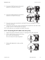
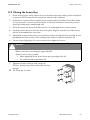
8.3 Opening SMA DC Disconnect
1. Turn the SMA DC Disconnect off by turning the switch to ”0” (A).
2. Loosen the screw in the right area of the SMA DC Disconnect (B) using a small phillips
screwdriver (used screw: UNC no 5 x 3⁄4 in. cross recess Phillips pan head machine screw). Do
not remove the screw. Check if you can remove the knob of the SMA DC Disconnect. If not,
unscrew the screw further until you can remove the knob. The screw is attached with a rubber
washer in order to make the assembly easier.
3. Remove the screw and the washer from the bottom side of the SMA DC Disconnect (C), which
fastens the lid.
4. Pull off the switch handle.
5. Remove the lid of the SMA DC Disconnect by pulling
it down and moving it at the same time carefully
forward at its lower edge.
☑ The SMA DC Disconnect is open.
50
SB8-10TL-IUS103811
Installation Guide
SMA America, LLC
Opening and closing
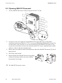
8.4 Closing SMA DC Disconnect
1. Position the lid onto the SMA DC Disconnect. Insert
the switch handle into the lid.
2. Turn the switch handle to position ”0” (A).
3. Tighten the screw on the right side of the switch handle (B) using a small phillips screwdriver
(used screw: UNC no 5 x 3⁄4 in. cross recess Phillips pan head machine screw).
4. Install the screw and washer at the bottom side of the SMA DC Disconnect (C), to fasten the lid.
The teeth of the washer must face toward the lid in order to ensure proper grounding. Tighten
the screw to a torque of 44 in‑lbs. (5 Nm).
Installation Guide
SB8-10TL-IUS103811
51
Maintenance
SMA America, LLC
9 Maintenance
9.1 Checking heat dissipation
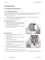
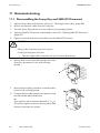
9.1.1 Cleaning the fans
If the fan guards are only dirtied with loose dust, they can be cleaned with a vacuum cleaner. If you
do not achieve satisfactory results with a vacuum cleaner, dismantle the fan for cleaning.
To do so, proceed as follows:
1. Disconnect the Sunny Boy from both the DC and AC connections, as described in section
8.1 ”Opening the Sunny Boy” (page 48)
2. Wait for the fans to stop rotating.
Cleaning the fan guards
3. Push the two latches at the right edge of the black
plastic cover to one side. Remove it carefully with
the fan guards mounted behind it.
4. Clean the fan guard with a soft brush, a paint brush,
a cloth, or compressed air.
Cleaning the fan
5. Press the front latches backwards and the rear
latches forwards.
6. Remove the fan by pulling it slowly and carefully
downwards.
7. Unlock and remove the plugs.
The fan cables are long enough for lifting the fans
far enough out to disconnect the internal plugs in
the Sunny Boy.
8. Remove the fan and clean it with a soft brush, a
paint brush, or a cloth and water.
Do not use compressed air as this can damage the
fan.
9. After cleaning, assemble everything in reverse order.
10. Check that the fans are functional as described in section 9.2.1 ”Checking the fans” (page 54).
52
SB8-10TL-IUS103811
Installation Guide
SMA America, LLC
Maintenance
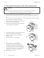
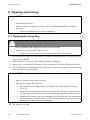
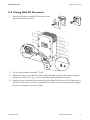
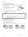
9.1.2 Cleaning the handle covers
The Sunny Boy sucks air in from underneath via the fans and blows it out again at the top on both
sides via the handle covers. Clean the handle covers, if they are dirty. Proceed as follows:
1. Remove the handle covers.
Insert your finger above in the space between the
handle cover and the housing and remove the
handle covers to the side.
2. Clean the handle covers with a soft brush, a paint brush, or compressed air.
3. Fasten the handle covers back onto the Sunny Boy.
The handle covers must be attached according to the inside inscription ("links/left" and
"rechts/right").
NOTICE
Insects entering the Sunny Boy can damage the inverter.
• The handle covers must not be removed permanently. Otherwise the device is not
protected against the entrance of insects.
9.2 Checking the DC Disconnect
Under normal use the DC Disconnect does not need maintenance.
It is recommended, though not compulsory to:
• Check the DC Disconnect regularly.
• Operate the DC Disconnect once a year 10 times.
Operating the switch will clean the contacts and will extend the life of the DC Disconnect.
Installation Guide
SB8-10TL-IUS103811
53
Maintenance
SMA America, LLC
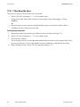
9.2.1 Checking the fans
There are two ways to check that the fan is functional:
• Set the "Fan Test" parameter to ”1” in the installer mode
(using Sunny Data, Sunny Data Control, the Sunny Boy Control data logger, or Sunny
WebBox),
or
• place the jumpers on the system control board (the jumpers required to check the fans is
included in the Sunny Boy accessories kit).
Setting the parameter
1. Request the installer password on the SMA Serviceline (contact: see Page 71).
2. Set the "Fan Test" parameter to ”1” in the installer mode.
3. Check the fans air-flow.
The Sunny Boy sucks air in from underneath and then blows it back out on the upper sides. Listen
for any unusual noise, which could indicate incorrect installation or that the fans are faulty.
4. After checking the fans, set the "Fan Test" parameter back to ”0”.
54
SB8-10TL-IUS103811
Installation Guide
SMA America, LLC
Troubleshooting
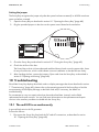
Setting the jumper
The Sunny Boy recognizes the jumper only after the system has been restarted (i.e. all LEDs must have
gone out before a restart).
1. Open the Sunny Boy as described in section 8.1 ”Opening the Sunny Boy” (page 48)
2. Plug the provided jumpers in the slots on the system control board as shown below.
3. Close the Sunny Boy as described in section 8.2 ”Closing the Sunny Boy” (page 49).
4. Check the air-flow of the fans.
The Sunny Boy sucks air in from underneath and then blows it back out on the upper sides. Listen
for any unusual noise, which could indicate incorrect installation or that the fans are faulty.
5. After checking the fans, remove the jumpers. Open and close the Sunny Boy as described in
section 8 ”Opening and closing” (page 48).
10 Troubleshooting
Should the Sunny Boy display other blink codes or display messages than those described in section
7 ”Commissioning” (page 42), please refer to the operating manual of the Sunny Boy to find the
exact meaning of the display message or the blink code and, if necessary, the details on
troubleshooting.
Do not attempt to carry out repairs other than those described here. Instead, use the SMA
replacement and repair services. You can find more information on the replacement and repair
services in the warranty conditions included with the Sunny Boy.
10.1 The red LED is on continuously
A ground fault exists in the PV generator
Proceed as follows:
1. Disconnect the Sunny Boy from both the DC and AC connections, as described in section
8.1 ”Opening the Sunny Boy” (page 48).
Installation Guide
SB8-10TL-IUS103811
55
Troubleshooting
SMA America, LLC
NOTICE
Excessive voltages can destroy the measuring device.
• Only use measuring devices with a DC input voltage range up to at least 600 V.
2. Measure the voltages between the plus and minus pole of a string against the ground potential.
If voltage is found, there is a ground fault in the corresponding string.
DANGER
In case of a ground fault, the PV generator may carry high voltages.
Risk of lethal electric shock.
• Do not touch the frame of the PV generator.
• Do not touch PE.
• Wait until no voltage can be measured.
• Do not connect strings with ground faults to the Sunny Boy.
The approximate position of the ground fault can be determined from the ratio of the measured
voltages between plus against ground potential and minus against ground potential.
Example:
The ground fault is between the second and third module in this case.
3. Repeat step 2 for each string.
4. Fix the ground fault in the affected string.
5. Restart the Sunny Boy as described in section 8.2 ”Closing the Sunny Boy” (page 49).
56
SB8-10TL-IUS103811
Installation Guide
SMA America, LLC
Troubleshooting
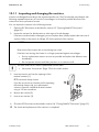
10.1.1 Inspecting and changing the varistors
Varistors are designed according to the expected product use. Their functionality may diminish with
following repeated responses as a result of overvoltages. It is therefore possible that one of the
varistors has lost its protective function.
You can inspect the varistors in the following manner:
1. Open the DC Disconnect as described in section 8.3 ”Opening SMA DC Disconnect”
(page 50).
2. Inspect the varistors for discoloration or other signs of visual damage.
If varistors are discolored or damaged, you must replace them. Always replace the entire set of
varistors. Refer to the section 6.4 (Page 30) for the position of the varistors.
NOTICE
Destruction of the inverter due to overvoltage can result.
If varistors are missing, the inverter is no longer protected against overvoltages.
• Procure replacement varistors as soon as possible and replace the defective ones
immediately.
• Do not operate inverters with faulty varistors or no varistors at all.
You must order an AC varistor replacement kit from SMA.
• See section "Accessories" (Page 70) for the order number.
3. Insert an insertion tool into the openings of the
terminal contacts (1).
☑ The terminal clamps loosen.
If you do not receive an insertion tool for operating
the terminal clamps with your replacement
varistors: Open the individual terminal contacts
using a 3.5 mm screwdriver.
4. Remove the varistor (2).
5. Insert a new varistor (3).
6. Close the DC Disconnect as described in section 8.4 ”Closing SMA DC Disconnect” (page 51).
☑ The check and replacement of the varistors is completed.
Installation Guide
SB8-10TL-IUS103811
57
Decommissioning
SMA America, LLC
11 Decommissioning
11.1 Disassembling the Sunny Boy and SMA DC Disconnect
1. Open the Sunny Boy as described in section 8.1 ”Opening the Sunny Boy” (page 48).
2. Remove all connector cables from the Sunny Boy.
3. Close the Sunny Boy with the six screws and the corresponding washers.
4. Open the SMA DC Disconnect as described in section 8.3 ”Opening SMA DC Disconnect”
(page 50).
5. Open the terminals and remove all cables from the SMA DC Disconnect.
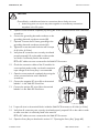
CAUTION
Falling of the Sunny Boy may cause injuries.
Crushing of body parts will result.
• Take the weight of the Sunny Boy into account when dismounting.
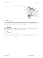
6. Remove both screws on the left and right side of the
Sunny Boy that attach it to the wall mounting
bracket.
7. Remove the Sunny Boy upwards in a vertical position
from the wall mounting bracket.
8. Transport the Sunny Boy between two persons, using
the side handles above and below.
or
Put a steel bar with a maximum diameter of 11⁄8 in.
(30 mm) through the enclosure opening above and
transport it between two people.
58
SB8-10TL-IUS103811
Installation Guide
SMA America, LLC
Decommissioning
9. Remove the screws left and right on the SMA DC
Disconnect which attach it.
11.2 Packaging
If possible, always pack the Sunny Boy and the SMA DC Disconnect in the original packaging. If this
is no longer available, use a similar box with a handle system which can withstand the weight of the
Sunny Boy and the SMA DC Disconnect and can be closed fully.
11.3 Storage
Store the Sunny Boy and the SMA DC Disconnect in a dry place where ambient temperatures are
always between − 13 °F ... +140 °F ( − 25 °C ... +60 °C).
11.4 Disposal
Dispose the Sunny Boy and SMA DC Disconnect at the end of its service life in accordance with the
disposal regulations for electronic scrap which apply at the installation site at that time. Alternatively,
send it back to SMA with shipping paid by sender, and labeled "FOR DISPOSAL" (contact: see
Page 71).
Installation Guide
SB8-10TL-IUS103811
59
Technical data
SMA America, LLC
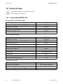
12 Technical data
Specifications subject to change without notice.
Values at nominal conditions.
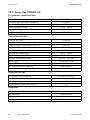
12.1 Sunny Boy 8000TL-US
PV generator connection data
Maximum DC power
Maximum array input power (DC@STC)
Maximum DC voltage
Peak power track voltage
Maximum DC input current
Number of MPP-Trackers
8,300 W
10,000 W
600 V
300 V ... 480 V
28 A
1 (OptiTrac)
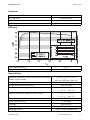
Grid connection data
Nominal AC power
Maximum AC power
Reduced power output at 140 °F (60 °C)
Maximum AC current
Nominal AC voltage
Nominal AC voltage range
Nominal AC frequency
Nominal AC frequency range
Power factor
Current THD
AC connection/power balancing
Ground fault monitoring (R-Iso)
8,000 W
8,000 W
8,000 W
40 A
208 V
183 V ... 229 V
60 Hz
59.3 HZ ... 60.5 Hz
1 at Nominal Power
<4%
Dual Phase/O
yes
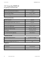
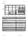
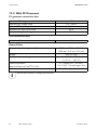
Protection Devices
DC reverse polarity protection
AC short circuit protection
AC overcurrent protection
Grid monitoring (SMA Grid Guard® 2)
60
SB8-10TL-IUS103811
yes, short circuit diode
yes, software controlled
yes, current controlled
yes
Installation Guide
SMA America, LLC
Technical data
Equipment
DC connection
AC connection
LCD display
Optional communication interfaces
screw terminals
screw terminals
yes
RS485 or wireless (Bluetooth)
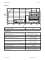
Efficiency
Peak inverter efficiency
Weighted efficiency (CEC)
98.3 %
98 %
General Data
Maximum dimensions, inverter and disconnect combined
(width x height x depth)
Weight of the inverter
Weight of the SMA DC disconnect
Ambient temperature range
Ambient temperature range (full power output)
Power consumption nighttime
Noise emission, typical
Topology
Cooling concept
Mounting location
Installation Guide
183⁄8 in. x 33 in x 97⁄16 in.
467 mm x 838 mm x 241 mm
77 lbs. (35 kg)
8 lbs. (3.5 kg)
− 13 °F ... +140 °F
( − 25 °C ... +60 °C)
− 13 °F ... +113 °F
( − 25 °C ... +45 °C)
≤ 0.25 W
≤ 46 dB(A)
transformerless
OptiCool
indoor/outdoor (NEMA 3R)
SB8-10TL-IUS103811
61
Technical data
SMA America, LLC
12.2 Sunny Boy 9000TL-US
PV generator connection data
Maximum DC power
Maximum array input power (DC@STC)
Maximum DC voltage
Peak power track voltage
Maximum DC input current
Number of MPP-Trackers
9,300 W
11,250 W
600 V
300 V ... 480 V
31 A
1 (OptiTrac)
Grid connection data
Nominal AC power
Maximum AC power
Reduced power output at 140 °F (60 °C)
Maximum AC current
Nominal AC voltage
Nominal AC voltage range
Nominal AC frequency
Nominal AC frequency range
Power factor
Current THD
AC connection/power balancing
Ground fault monitoring (R-Iso)
9,000 W
9,000 W
8,000 W
44 A
208 V
183 V ... 229 V
60 Hz
59.3 HZ ... 60.5 Hz
1 at Nominal Power
<4%
Dual Phase/O
yes
Protection Devices
DC reverse polarity protection
AC short circuit protection
AC overcurrent protection
Grid monitoring (SMA Grid Guard® 2)
yes, short circuit diode
yes, software controlled
yes, current controlled
yes
Equipment
DC connection
AC connection
LCD display
Optional communication interfaces
62
SB8-10TL-IUS103811
screw terminals
screw terminals
yes
RS485 or wireless (Bluetooth)
Installation Guide
SMA America, LLC
Technical data
Efficiency
Peak inverter efficiency
Weighted efficiency (CEC)
98.3 %
98 %
General Data
Maximum dimensions, inverter and disconnect combined
(width x height x depth)
Weight of the inverter
Weight of the SMA DC disconnect
Ambient temperature range
Ambient temperature range (full power output)
Power consumption nighttime
Noise emission, typical
Topology
Cooling concept
Mounting location
Installation Guide
183⁄8 in. x 33 in x 97⁄16 in.
467 mm x 838 mm x 241 mm
77 lbs. (35 kg)
8 lbs. (3.5 kg)
− 13 °F ... +140 °F
( − 25 °C ... +60°C)
− 13 °F ... +113 °F
( − 25 °C ... +45 °C)
≤ 0.25 W
≤ 46 dB(A)
transformerless
OptiCool
indoor/outdoor (NEMA 3R)
SB8-10TL-IUS103811
63
Technical data
SMA America, LLC
12.3 Sunny Boy 10000TL-US
PV generator connection data
Maximum DC power
Maximum array input power (DC@STC)
Maximum DC voltage
Peak power track voltage
Maximum DC input current
Number of MPP-Trackers
10,350 W
12,500 W
600 V
300 V ... 480 V
35 A
1 (OptiTrac)
Grid connection data
Nominal AC power
Maximum AC power
Reduced power output at 140 °F (60 °C)
Maximum AC current
Nominal AC voltage
Nominal AC voltage range
Nominal AC frequency
Nominal AC frequency range
Power factor
Current THD
AC connection/power balancing
Ground fault monitoring (R-Iso)
10,000 W
10,000 W
8,000 W
48 A
208 V
183 V ... 229 V
60 Hz
59.3 Hz ... 60.5 Hz
1 at Nominal Power
<4%
Dual Phase/O
yes
Protection Devices
DC reverse polarity protection
AC short circuit protection
AC overcurrent protection
Grid monitoring (SMA Grid Guard® 2)
yes, short circuit diode
yes, software controlled
yes, current controlled
yes
Equipment
DC connection
AC connection
LCD display
Optional communication interfaces
64
SB8-10TL-IUS103811
screw terminals
screw terminals
yes
RS485 or wireless (Bluetooth)
Installation Guide
SMA America, LLC
Technical data
Efficiency
Peak inverter efficiency
Weighted efficiency (CEC)
98.3 %
97.5 %
General Data
Maximum dimensions, inverter and disconnect combined
(width x height x depth)
Weight of the inverter
Weight of the SMA DC disconnect
Ambient temperature range
Ambient temperature range (full power output)
Power consumption nighttime
Noise emission, typical
Topology
Cooling concept
Mounting location
Installation Guide
183⁄8 in. x 33 in x 97⁄16 in.
467 mm x 838 mm x 241 mm
77 lbs. (35 kg)
8 lbs. (3.5 kg)
− 13 °F ... +140 °F
( − 25 °C ... +60 °C)
− 13 °F ... +113 °F
( − 25 °C ... +45 °C)
≤ 0.25 W
≤ 46 dB(A)
transformerless
OptiCool
indoor/outdoor (NEMA 3R)
SB8-10TL-IUS103811
65
Technical data
SMA America, LLC
12.4 SMA DC Disconnect
PV generator connection data
Maximum DC voltage
Operating DC voltage range
Maximum DC operating current
Maximum DC short circuit current
Maximum String Fuse Rating
600 V
0 V ... 600 V
35 A
45 A
20 A
Grid connection data
Maximum AC current
48 A
General Data
Dimensions (width x height x depth)
Weight
Ambient temperature range
Cable requirements
(National Electrical Code® 310.16)
Enclosure
7.87 in. x 12.20 in. x 7.48 in.
(200 mm x 310 mm x 190 mm)
8 lbs. (3.5 kg)
− 13 °F ... +140 °F
( − 25 °C ... +60 °C)
8 ... 2 AWG (10 … 35 mm²),
194 °F (90 °C) rated copper wire
NEMA 3R rated, indoor/outdoor
Specifications subject to change without notice.
66
SB8-10TL-IUS103811
Installation Guide
SMA America, LLC
Technical data
12.5 FCC compliance information
SMA Utility Interactive Inverter, Model Sunny Boy
This device complies with Part 15 of the FCC Rules. Operation is subject to the following conditions:
(1) This device may not cause harmful interference, and
(2) this device must accept any interference received, including interference that may cause undesired
operation.
NOTE: This equipment has been tested and found to comply with the limits for a Class A & B digital
device, pursuant to Part 15 of the FCC Rules. These limits are designed to provide reasonable
protection against harmful interference in a residential installation. This equipment generates, uses,
and can radiate radio frequency energy and if not installed and used in accordance with the
instructions, may cause harmful interference to radio communications. However, there is no guarantee
that interference will not occur in a particular installation. If this equipment does cause harmful
interference to radio or television reception, which can be determined by turning the equipment off
and on, the user is encouraged to try to correct the interference by one or more of the following
measures:
• Reorient or relocate the receiving antenna.
• Increase the separation between the equipment and the receiver.
• Connect the equipment into an outlet on a circuit different from that to which the receiver is
connected.
• Consult the dealer or an experienced radio/TV technician for help.
• The user is cautioned that changes or modifications not expressly approved by SMA America,
Inc. could void the user’s authority to operate this equipment.
Installation Guide
SB8-10TL-IUS103811
67
Technical data
SMA America, LLC
12.6 Trip limits/trip times
Nominal
frequency
60 Hz
Trip limit
Trip frequencies
Trip times
> 60.5 Hz
< 57.0 Hz ... 59.8 Hz
(default 59.3 Hz)
60.45 Hz ... 60.55 Hz
56.95 Hz ... 59.85 Hz
(default 59.25 Hz ...
59.35 Hz)
56.95 Hz ... 57.05 Hz
max. 0.1602 s
adjustable 0.16 s ... 300 s
(default max. 0.1602 s)
< 57.0 Hz
Voltage
208 V
Trip limit trip
voltages
50 %
88 %
110 %
120 %
Line-to-neutral*
57.6 ... 62.4 V
103.2 ... 108.0 V
129.6 ... 134.4 V
141.6 ... 146.4 V
Trip voltages
line-to-line*
99.8 ... 108.2 V
178.9 ... 187.2 V
224.6 ... 233.0 V
245.4 ... 253.8 V
max. 0.1602 s
Trip times
max. 0.1602 s
max. 2.002 s
max. 1.001 s
max. 0.1602 s
* The intervals result from the measuring accuracies listed below.
Manufacturer’s accuracies:
Trip limit accuracy: ± 2 % of nominal grid voltage
Trip time accuracy: ± 0.1 % of nominal trip time
Trip frequency accuracy: ± 0.1 % of nominal frequency
68
SB8-10TL-IUS103811
Installation Guide
SMA America, LLC
Accessories
12.7 Torque values and wire sizes
Terminal
AC terminal blocks inverter
in-lbs
40
Nm
4.5
DC terminal blocks inverter
40
4.5
AC terminal blocks DC
Disconnect
40
4.5
DC terminal blocks DC
Disconnect
40
4.5
Grounding electrode conductor
terminal block DC Disconnect
40
4.5
Screws for fastening the Sunny
Boy and the DC Disconnect to
the wall mounting bracket and
closing the DC Disconnect lid
Lid screws
44
5
Wire size
6 ... 2 AWG (16 … 35 mm²),
194 °F (90 °C) rated copper
wire (NEC 310.16)
8 ... 2 AWG (10 … 35 mm²),
194 °F (90 °C) rated copper
wire
6 ... 2 AWG (16 … 35 mm²),
194 °F (90 °C) rated copper
wire (NEC 310.16)
8 ... 2 AWG (10 … 35 mm²),
194 °F (90 °C) rated copper
wire (NEC 310.16)
8 ... 2 AWG (10 … 35 mm²),
194 °F (90 °C) rated copper
wire (NEC 310.16)
---
53
6
---
13 Accessories
You will find the corresponding accessories and replacement parts for your product in the following
overview. If needed, you can order these from SMA or your SMA dealer.
Name
Sunny Boy Combiner Box
Power Balancer set
RS485 upgrade kit
Bluetooth upgrade set
Air grills
AC varistors
Installation Guide
Description
String combiner for 6 strings maximum
Upgrade kit for the Power Balancer
function
RS485 interface
Bluetooth communication interface
Air grill set "right and left" as replacement
part
AC varistor replacement kit
SMA order number
SBCBTL6-10
PBL-SBUS-10-NR
485USPB-SMC-NR
BTPBINV-NR
45-7202
SB-VAC-US01
SB8-10TL-IUS103811
69
Contact
SMA America, LLC
14 Contact
If you have technical problems concerning our products, contact your installer or the SMA Serviceline.
We require the following information in order to provide you with the necessary assistance:
• Inverter type
• Type and number of modules connected
• Communication method
• Serial number of the Sunny Boy
• Failure or warning number of the Sunny Boy
• Display of the Sunny Boy
SMA Solar Technology America, LLC
6020 West Oaks Blvd
Rocklin, CA 95765
Tel. +1 916 625 0870
Tel. +1 877-MY SMA TECH
Tel. +1 877 697 6283 (Toll free, available for USA, Canada and Puerto Rico)
Fax +1 916 625 0871
[email protected]
www.SMA-America.com
70
SB8-10TL-IUS103811
Installation Guide
4.""NFSJDB1SPEVDUJPO--$
XXXTNBBNFSJDBDPN
XXX4.""NFSJDBDPN