Transcript
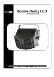
NL100 DMX USER MANUAL
CAUTION!
Keep this device away from rain and moisture!
Unplug mains lead before opening the housing!
For your own safety, please read this user manual carefully before you initially start-up.
FEATURES
*LED Double Derby Effect with R, G, B beams from the 12 lenses
*DMX-512 control via regular DMX-controller (occupies 2 channels)
*Sound-controlled via built-in microphone
*Microphone-sensitivity adjustable via rotary-control
*Strobe effect
*8 internal programs
*Master/Slave function
*Particularly bright illuminating by high power 3W LEDs
*Advantages of LED-technology: extremely long life of the LEDs, low
power consumption, minimal heat emission, maintenance free with
brilliant light radiation
OPERATION
After you connected the device to the mains, the NL100 DMX LED DOUBLE DERBY RGB starts running.
STAND ALONE OPERATION
In Stand Alone Operation you can use the NL100 DMX LED DOUBLE DERBY RGB without a controller.
For sound controlled operation set all DIP Switches to OFF.
You can do without a controller as the NL100 DMX LED DOUBLE DERBY RGB features a built-in microphone,
which provides automatic sound control. You can adjust the sensitivity with the rotary-control on the rear panel.
SOUND-CONTROL OPERATION:
For sound controlled operation set all DIP Switches to OFF.
MASTER/SLAVE OPERATION
The master/slave-operation enables that several devices can be synchronized and controlled by one master-device. On the rear panel of the
NL100 DMX LED DOUBLE DERBY RGB you can find an XLR-jack and an XLR-plug, which can be used for connecting several devices. Choose
the device which is to control the effects. This device then works as master-device and controls all
other slave-devices, which are to be connected to the master-device via a stereo shielded cable. Connect the OUT-jack with the IN-plug of the
next device.
Set all DIP Switches to OFF in order to determine the Master device. Set DIP Switches 1 and 10 to ON in order to determine the Slave device.
DMX-CONTROL OPERATION
You can control the spots individually via your DMX-controller. Every DMX-channel has a different occupation with different features.
For DMX-controlled operation set DIP Switch 10 to ON.
Building a serial DMX-chain:
Connect the DMX-output of the first fixture in the DMX-chain with the DMX-input of the next fixture. Always connect one output with the input of
the next fixture until all fixtures are connected.
Caution: At the last fixture, the DMX-cable has to be terminated with a terminator. Solder a 120 Ω resistor between Signal (–) and Signal (+) into a
3-pin XLR-plug and plug it in the DMX-output of the last fixture.
Addressing
Each device occupies 2 channels. To ensure that the control signals are properly directed to each device, the device requires addressing. This is
to be adjusted for every single device by changing the DIP-switches as set out in the table below.
The starting address is defined as the first channel from which the device will respond to the controller. Please make sure that you do not have
any overlapping channels in order to control each device correctly and independently from any other fixture on the DMX data link. If two, three or
more devices are addressed similarly, they will work similarly.
Controlling: After having addressed all devices, you may now start operating these via your controller.
DMX PROTOCOL
Channel 2 – Motor Rotation
Channel 1 – Control/Operating Mode
001 – 085
Counter-clockwise motor rotation (Slow ~ Fast)
000 – 014
No function
086 – 170
Clockwise motor rotation (Slow ~ Fast)
015 – 100
LED’s on
171 – 255
Motor rotation right-to-left-to-right (Slow ~ Fast)
101 – 255
Auto
CLEANING AND MAINTENANCE
Please use a soft lint-free and moistened cloth clean frequently. Never use alcohol or solvents! There are no serviceable parts inside the device
except for the fuse. Maintenance and service operations are only to be carried out by authorized dealers.
Replacing the fuse
Before replacing the fuse, unplug mains lead.
Procedure:
Step 1: Take out the fuseholder under the power supply.
Step 3: Install the new fuse in the fuseholder.
Step 2: Remove the old fuse from the fuseholder.
Step 4: Replace the fuseholder in the housing and fix it.
If the power supply cable of this device becomes damaged, it has to be replaced by authorized dealers only in order to avoid hazards.
TECHNICAL SPECIFICATIONS
* Power supply: 220 VAC, 50-60 Hz
* Maximum housing temperature TB (steady state): 60° C
* Power consumption: 20W
* Min.distance from flammable surfaces: 0.50 m
* Number of DMX channels: 2
* Min.distance to lighted object: 0.10 m
* DMX-512 connection: 3-pin XLR
* Fuse: F 1 A, 250V
* Sound-control: via built-in microphone via built-in microphone
* Weight: 2.75 kg
* Maximum ambient temperature Ta: 45° C
Please note: Every information is subject to change without prior notice.