1
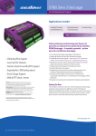
SUPPLEMENTAL USER’S MANUAL
HANDI-LOGGER PORTABLE
With LOG-A-C2 SOFTWARE
Serial No.________________
1336 Brommer Street
Santa Cruz, CA 95062 USA
Tel (831) 462-2801
Fax (831) 462-4418
[email protected]
www.geomechanics.com
Copyright ©2002 by Applied Geomechanics Inc. All rights reserved.
Document No. B-02-1005, Rev. A
TABLE OF CONTENTS
1
Getting Started .........................................................................................................................1
2
System Components.................................................................................................................2
3
Basic System Requirements ....................................................................................................3
3.1
4
5
Communications Set-up .....................................................................................................3
Set-up and Configuration........................................................................................................4
4.1
Hardware Set-up................................................................................................................4
4.2
Software Installation..........................................................................................................4
4.3
Starting PC208W ...............................................................................................................5
4.4
Setting the Datalogger Clock.............................................................................................5
4.5
Instrument Configuration...................................................................................................6
4.6
Mode 4 Parameters............................................................................................................6
Running the Handi-Logger Portable ......................................................................................7
Appendix A – Setup Tables.............................................................................................................9
Appendix B – LOG-A-C2 Program..............................................................................................10
LIST OF FIGURES
Figure 1. Handi-Logger Portable .....................................................................................................1
Figure 2. Handi-Logger Portable Control Panel ..............................................................................2
Figure 3. Wiring Diagram for Handi-Logger Portable ....................................................................8
1
Getting Started
The Handi-Logger Portable is a weatherproof datalogger with Ethernet communications and extra data
storage capacity designed for use with one Applied Geomechanics 700-Series Biaxial Tiltmeter. The
Handi-Logger Portable is equipped with weatherproof external connectors for tiltmeter, Ethernet and
power connections (Figure 1). A power switch and power indicator LED are present on the control panel
(Figure 2).
This datalogger is a special version of the Model 798-A Handi-Logger. This manual is a supplement to the
Model 798-A Handi-Logger User’s Manual (document no. B-01-1008) and should be used in conjunction
with that document to identify and understand the differences between the two devices and the datalogging
software supplied with them (LOG-A-C for the Model 798-A and LOG-A-C2 for the Handi-Logger
Portable.
While the Model 798-A with LOG-A-C Software is designed for use with either telephone, cellular or radio
communications, the Handi-Logger Portable with LOG-A-C2 software is equipped with an NL100
Ethernet link instead. The words NL100 or Ethernet Link should be substituted for the words telephone,
cellular phone or radio when these terms are used in the Model 798-A Handi-Logger Manual.
Figure 1. Handi-Logger Portable
B-02-1005, Rev. A
1
2
System Components
Each Handi-Logger Portable consists of the following components. Please take a moment to make sure
that they are all present in your shipment:
•
•
•
•
•
•
Handi-Logger Portable equipped with an NL100 Ethernet Link and SM4M 4 megabyte data
storage module, internal DC/DC converter, and NL100 power relay.
Internal wiring diagram in the lid of the unit (Figure 3).
Mating power connector for your use in connecting your external power supply (11-15 VDC).
This connector also contains a pin for connecting your system to earth ground.
10 Base-T Field Installable Waterproof Housings to be used on your Ethernet connection to the
Handi-Logger Portable.
RJ45 10BaseT crossover cable to be used to connect a PC directly to the Handi-Logger Portable’s
Ethernet port. Please note that this cable will not work for a network connection to the Ethernet
port because this connection requires a straight through RJ45 10BaseT cable.
Tiltmeter with connector on the end of its cable, or loose connector ready for installation on by the
user.
The following software has also been provided (one set of disks or CD per order):
•
•
PC208W Datalogger Support Software
LOG-A-C2 datalogger software
Figure 2. Handi-Logger Portable Control Panel
B-02-1005, Rev. A
2
3
Basic System Requirements
The system requirements are the same as for the Model 798-A Handi-Logger.
3.1
Communications Set-up
Your system is factory configured to communicate primarily using the Ethernet link and NL100 interface.
A table of TCP/IP addresses and serial numbers for each Handi-Logger Portable is provided in Appendix
A. Direct connection with the Handi-Logger Portable can be established using a 10 Base-T Category 5
Crossover Cable between the PC and the Ethernet connector on the case. Direct serial communication with
the NL100 can be established by removing the face plate inside the Handi-Logger Portable enclosure and
connecting to the serial port on the NL100 inside. Serial communication is required to enter the NL100
Conf/Mon (Configuration Monitor) mode to change the settings in the NL100. A summary of the initial
Conf/Mon settings is provided in Appendix A.
B-02-1005, Rev. A
3
4
Set-up and Configuration
4.1
Hardware Set-up
1.
Connect the tiltmeter to the Handi-Logger Portable using the 10-Pin connector. Prior to making
this connection, the tiltmeter should be leveled using a Model 771 Digital Readout Unit or two
digital voltmeters. The tiltmeter should be leveled to bring the output on both the X and Y
channels close to 0 mV. Tiltmeter output greater than ±2.5 volts will be out of range for the HandiLogger and will result in an “out of range” indicator of –9999 in the recorded data.
2.
Connect the external 12-Volt power supply to the Power connection on the side of the HandiLogger Portable using the 3-pin connector and mate provided. When wiring the 3-pin connector,
terminal A goes to the battery ground, terminal B goes to +12 Volts and terminal C is used for an
earth ground connection, if desired.
3.
Connect to a LAN or PC using the Ethernet connection on the side of the Handi-Logger Portable.
A waterproof housing is provided for this connection but any standard 10 Base-T Category 5 Cable
with RJ 45 connector can be used. The waterproof housing should be used when the system is
deployed outside. The crossover cable included with your system can be used for a direct
connection to a PC using the Ethernet port.
4.
Turn on the Handi-Logger Portable using the power switch inside the case. When power is on, the
Logger will begin operation and the LED on the panel will flash once every 5 seconds. The NL100
should receive power within about 1 minute after startup of the logger.
4.2
Software Installation
With your datalogger your received PC208W and LOG-A-C2 software.
For proper operation of the Handi-Logger Portable it is important to install the software into the correct
directories in the order described below:
First install PC208W on your PC. All of the data collection and other interactions with the Handi-Logger
Portable are performed through PC208W.
The LOG-A-C2 Software CD contains files which give the Handi-Logger Portable the ability to function
properly as a datalogger compatible with the type of instruments you are using. These files include the
datalogger program (LOG-A-C2.DLD), the communications set-up files (PC208W.dnd) and files which
configure the displays with which you will interact with the Handi-Logger Portable (*.INI files and *.PFL
files). These files must be installed in the proper folders after PC208W has been installed. The files
included on the LOG-A-C2 Software CD and their final destinations are summarized below:
1. LOG-A-C2.DLD is the datalogger program installed in the Handi-Logger Portable. This file
should be copied directly into the C:/PC208W folder. A text copy of this file LOG-A-C2.CSI is
also provided on the CD. A printout of LOG-A-C2.CSI is included in Appendix B of this manual.
If desired, you can also copy this file from the CD directly to the C:/PC208W folder so that it can
be accessed from your PC at a later time.
B-02-1005, Rev. A
4
2. PC208W.dnd contains the communications set-up files required by PC208W for communication
with each of your Handi-Logger Portables. This file should be copied directly from the CD to the
C:/PC208W folder. This file will replace a generic version PC208W.dnd that was installed by
PC208W upon installation of that program. When copying this file to the C:/PC208W folder,
Windows will generate a message indicating that “this file already exists, do you want to replace
the existing file?” You should answer yes to complete the installation.
3. The CD contains N files each with the suffixes .INI and .PFL, where N is the number of HandiLogger Portables included in your order. Each of the N have file names of HLP001 through
HLP0N (one file for each Handi-Logger Portable numbered 1 through N). All of these files
(HLP001.INI through HLP0N.INI and HLP001.PFL through HLP0N.PFL) should be copied into
the C:/PC208W/INIFILES folder. These files provide the input data tables and the port and flag
settings for each Handi-Logger Portable.
4.3
Starting PC208W
Start PC208W as indicated in the Model 798-A Handi-Logger manual.
Note: The station list on the PC208W Connection window will not be the same as in the Model 798-A
manual. Instead of two stations with the names Direct and Phone as shown in the manual, you will have
2N stations with device identification names of HLP001, SM4M1, HLP002, SM4M2, HPL003,
SM4M3…etc. These station names represent the N dataloggers and storage modules included in your
order. HLP001 for example represents one Handi-Logger Portable and SM4M1 represents the 4 megabyte
storage module in this Handi-Logger Portable. The table in Appendix A provides a cross reference of
serial numbers, device identifiers and TCP/IP addresses.
To connect to a Handi-Logger Portable or its storage module, the logger needs to be connected directly to
the PC using a crossover cable or connected to the PC over a LAN using a standard 10BaseT cable. To
make a connection, first click on the device identifier from the station list for the device you want to
connect to, and then click on connect.
If you have problems connecting to the Handi-Logger Portable using the Ethernet port over a LAN, you
may need to change the TCP/IP address and/or the Network Mask settings in the NL100 ConfMon
(Configuration Monitor) mode so that they will be compatible with your network. You should consult with
your network administrator and the NL100 Manual sections 2.2 and 2.3 prior to making these changes.
A summary of the ConfMon settings including the TCP/IP addresses programmed into each NL100 is
provided in Appendix A. If any TCP/IP addresses are changed in the Conf/Mon settings of the NL100, you
will also need to change the correspondiong TCP/IP address in PC208W. To change a TCP/IP address in
PC208W, open PC208W and click on the set-up button. From the set-up window, you will see a device
map on the left side of the screen. To change the TCP/IP for a given Handi-Logger Portable, simply click
on the socket number corresponding to that Handi-Logger Portable on the device map. You will see the
TCP/IP in a window to the right of the device map. After changing the TCP/IP to correspond to the new
TCP/IP programmed into the NL100 in Conf/Mon mode, be sure to save your changes. You do not need to
change the Socket Port Number.
4.4
Setting the Datalogger Clock
Set the datalogger clock as indicated in the Model 798-A manual.
B-02-1005, Rev. A
5
4.5
Instrument Configuration
The Handi-Logger Portable is shipped pre configured for Ethernet communication and operation of one
biaxial 700-Series Tiltmeter (e.g., Model 701-2A(4X)). If necessary, instrument set up can be performed as
indicated in the Model 798-A manual.
For the Handi-Logger Portable instrument set-up table, Inst_MUX1 should be set to “1”, Inst_MUX2 set to
“0” and ID-T1 set to the tiltmeter serial number. The last table in Appendix A provides the tiltmeter serial
numbers in the set-up table that were associated with each Handi-Logger Portable at the factory. To use a
Handi-Logger Portable with a different tiltmeter, simply change the tiltmeter serial number in the field next
to ID_T1 in the set-up table.
4.6
Mode 4 Parameters
The Mode 4 parameters are basically the same as indicated in the Model 798-A manual with the following
exception: Line numbers 12 and 13 relate to the NL100 power rather than to cell phone or radio power.
Additionally, while the default values are the same as indicated in the manual, the sample interval and
record intervals (Lines 0 and 1) have both been set to 10 minutes, the NL100 Turn on period (Line 12) has
been set to 1 minute, and the NL100 on duration (Line 13) has been set to 0 by the LOG-A-C2 software.
These are the settings that will be active when the Handi-Logger Portable is started. These settings will
provide a 10-minute sample and recording interval and will turn on the NL100 within 1 minute of startup
and leave it on continuously until the parameters for Lines 12 and 13 are reset. In order to save power, we
recommend that after initial testing and set-up, the NL100 turn-on period and duration be reset so that this
link is not always on.
If for any reason, the Mode 4 Parameters are reset to defaults or LOG-A-C2 is resent to the logger, the
Mode 4 Parameters will revert to those indicated on page 14 of the Model 798 LOG-A-C manual. If this
occurs, the sample and recording intervals will revert to 60 minutes and the NL100 will only be powered
for 15 minutes at the top of each hour according to the datalogger clock.
B-02-1005, Rev. A
6
5
Running the Handi-Logger Portable
Operation of the Handi-Logger Portable is as indicated in the Model 798-A manual.
Two additional ports have been added to the Ports/Flag window. Port 2 is highlighted if the NL100 power
relay is activated and Port 3 will flash once every 5 seconds along with the Power LED indicator (Figure
2).
B-02-1005, Rev. A
7
Figure 3. Wiring Diagram for Handi-Logger Portable
B-02-1005, Rev. A
8
Appendix A – Setup Tables
B-02-1005, Rev. A
9
Appendix B – LOG-A-C2 Program
B-02-1005, Rev. A
10