Download GOT2000 Connection Manual (Microcomputer, MODBUS, Peripherals)

Transcript
GRAPHIC OPERATION TERMINAL
GOT2000 Series
Connection Manual
(Microcomputer, MODBUS Products, Peripherals)
For GT Works3 Version1
■MICROCOMPUTER CONNECTION
■MODBUS/RTU CONNECTION
■MODBUS/TCP CONNECTION
■CONNECTION TO SOUND OUTPUT
UNIT
■CONNECTION TO EXTERNAL I/O
DEVICE
■BAR CODE READER CONNECTION
■REMOTE PERSONAL COMPUTER
OPERATION CONNECTION
■VNC(R) SERVER CONNECTION
■VIDEO/RGB CONNECTION
■PRINTER CONNECTION
■MULTIMEDIA CONNECTION
■RFID CONNECTION
■WIRELESS LAN CONNECTION
SAFETY PRECAUTIONS
(Always read these precautions before using this equipment.)
Before using this product, please read this manual and the relevant manuals introduced in this manual
carefully and pay full attention to safety to handle the product correctly.
The precautions given in this manual are concerned with this product.
In this manual, the safety precautions are ranked as "WARNING" and "CAUTION".
WARNING
Indicates that incorrect handling may cause hazardous conditions,
resulting in death or severe injury.
CAUTION
Indicates that incorrect handling may cause hazardous conditions,
resulting in medium or slight personal injury or physical damage.
Note that the
caution level may lead to a serious accident according to the circumstances. Always
follow the instructions of both levels because they are important to personal safety.
Please save this manual to make it accessible when required and always forward it to the end user.
[DESIGN PRECAUTIONS]
WARNING
Some failures of the GOT, communication unit or cable may keep the outputs on or off.
Some failures of a touch panel may cause malfunction of the input objects such as a touch switch.
An external monitoring circuit should be provided to check for output signals which may lead to a
serious accident.Not doing so can cause an accident due to false output or malfunction.
Do not use the GOT as the warning device that may cause a serious accident.
An independent and redundant hardware or mechanical interlock is required to configure the device
that displays and outputs serious warning.
Failure to observe this instruction may result in an accident due to incorrect output or malfunction.
The GOT backlight failure disables the operation on the touch switch(s).
When the GOT backlight has a failure, the POWER LED blinks (orange/blue) and the display section
dims. In such a case, the input by the touch switch(s) is disabled.
The display section of the GOT is an analog-resistive type touch panel.
[GT27]
The GOT is multi-touch compliant; however, do not touch three points or more simultaneously on the
display section. Doing so may cause an accident due to incorrect output or malfunction.
[GT23]
If you touch the display section simultaneously in two points or more,the switch that is located around
the center of the touched point, if any, may operate.Do not touch the display section in two points or
more simultaneously.Doing so may cause an accident due to incorrect output or malfunction.
When programs or parameters of the controller (such as a PLC) that is monitored by the GOT are
changed, be sure to reset the GOT, or turn on the unit again after shutting off the power as soon as
possible.Not doing so can cause an accident due to false output or malfunction.
A-1
[DESIGN PRECAUTIONS]
WARNING
If a communication fault (including cable disconnection) occurs during monitoring on the GOT,
communication between the GOT and PLC CPU is suspended and the GOT becomes inoperative.
For bus connection (GT27 Only) : The CPU becomes faulty and the GOT becomes inoperative.
For other than bus connection : The GOT becomes inoperative.
A system where the GOT is used should be configured to perform any significant operation to the
system by using the switches of a device other than the GOT on the assumption that a GOT
communication fault will occur.
Not doing so can cause an accident due to false output or malfunction.
CAUTION
Do not bundle the control and communication cables with main-circuit, power or other wiring.
Run the above cables separately from such wiring and keep them a minimum of 100mm apart.
Not doing so noise can cause a malfunction.
Do not press the GOT display section with a pointed material as a pen or driver.
Doing so can result in a damage or failure of the display section.
When the GOT is connected to the Ethernet network, the available IP address is restricted according
to the system configuration.
• When multiple GOTs are connected to the Ethernet network :
Do not set the IP address (192.168.3.18) for the GOTs and the controllers in the network.
• When a single GOT is connected to the Ethernet network :
Do not set the IP address (192.168.3.18) for the controllers except the GOT in the network.
Doing so can cause the IP address duplication.
The duplication can negatively affect the communication of the device with the IP address
(192.168.3.18).
The operation at the IP address duplication depends on the devices and the system.
Turn on the controllers and the network devices to be ready for communication before they
communicate with the GOT.
Failure to do so can cause a communication error on the GOT.
When the GOT is subject to shock or vibration, or some colors appear on the screen of the GOT, the
screen of the GOT might flicker.
[MOUNTING PRECAUTIONS]
WARNING
Be sure to shut off all phases of the external power supply used by the system before mounting or
removing the GOT main unit to/from the panel.
Not doing so can cause the unit to fail or malfunction.
Be sure to shut off all phases of the external power supply used by the system before mounting or
removing the option unit onto/from the GOT.(GT27 Only)
A-2
[MOUNTING PRECAUTIONS]
CAUTION
Use the GOT in the environment that satisfies the general specifications described in this manual.
Not doing so can cause an electric shock, fire, malfunction or product damage or deterioration.
When mounting the GOT to the control panel, tighten the mounting screws in the specified torque
range (0.36 N·m to 0.48 N·m) with a Phillips-head screwdriver No.2.
Undertightening can cause the GOT to drop, short circuit or malfunction.
Overtightening can cause a drop, short circuit or malfunction due to the damage of the screws or the
GOT.
When loading the communication unit or option unit other than wireless LAN unit to the GOT, fit it to
the connection interface of the GOT and tighten the mounting screws in the specified torque range
(0.36 N•m to 0.48 N•m) with a Phillips-head screwdriver No.2.
When loading the wireless LAN unit to the GOT, fit it to the side interface of GOT and tighten the
mounting screws in the specified torque range (0.10 N•m to 0.14 N•m) with a Phillips-head
screwdriver No.2.
Under tightening can cause the GOT to drop, short circuit or malfunction.
Overtightening can cause a drop, failure or malfunction due to the damage of the screws or
unit.(GT27 Only)
When closing the USB environmental protection cover, fix the cover to the GOT by pushing the
[PUSH] mark on the latch firmly to comply with the protective structure.(GT27 Only)
Remove the protective film of the GOT.
When the user continues using the GOT with the protective film, the film may not be removed.In
addition, for the models equipped with the human sensor function, using the GOT with the protective
film may cause the human sensor not to function properly
Operate and store the GOT in environments without direct sunlight, high temperature, dust, humidity,
and vibrations.
When using the GOT in the environment of oil or chemicals, use the protective cover for oil.Failure to
do so may cause failure or malfunction due to the oil or chemical entering into the GOT.
[WIRING PRECAUTIONS]
WARNING
Be sure to shut off all phases of the external power supply used by the system before wiring.
Failure to do so may result in an electric shock, product damage or malfunctions.
CAUTION
Make sure to ground the FG terminal and LG terminal of the GOT power supply section to the
protective ground conductors dedicated to the GOT with a ground resistance of 100 Ω or less.
When tightening the terminal screws, use a Phillips-head screwdriver No.2.
Terminal screws which are not to be used must be tightened always at torque 0.5 N·m to 0.8 N·m.
Otherwise there will be a danger of short circuit against the solderless terminals.
A-3
[WIRING PRECAUTIONS]
CAUTION
Use applicable solderless terminals and tighten them with the specified torque.
If any solderless spade terminal is used, it may be disconnected when the terminal screw comes
loose, resulting in failure.
Correctly wire the GOT power supply section after confirming the rated voltage and terminal
arrangement of the product.
Not doing so can cause a fire or failure.
Tighten the terminal screws of the GOT power supply section in the specified torque range (0.5 N·m
to 0.8 N·m).
Undertightening can cause a short circuit or malfunction.
Overtightening can cause a short circuit or malfunction due to the damage of the screws or the GOT.
Exercise care to avoid foreign matter such as chips and wire offcuts entering the GOT.
Not doing so can cause a fire, failure or malfunction.
The module has an ingress prevention label on its top to prevent foreign matter, such as wire offcuts,
from entering the module during wiring.
Do not peel this label during wiring.Before starting system operation, be sure to peel this label
because of heat dissipation. (GT27 Only)
Plug the communication cable into the GOT interface or the connector of the connected unit, and
tighten the mounting screws and the terminal screws in the specified torque range.
Undertightening can cause a short circuit or malfunction.
Overtightening can cause a short circuit or malfunction due to the damage of the screws or unit.
Plug the QnA/ACPU/Motion controller(A series) bus connection cable by inserting it into the
connector of the connected unit until it "clicks".
After plugging, check that it has been inserted snugly.
Not doing so can cause a malfunction due to a contact fault.(GT27 Only)
[TEST OPERATION PRECAUTIONS]
WARNING
Before performing the test operations of the user creation monitor screen (such as turning ON or
OFF bit device, changing the word device current value, changing the settings or current values of
the timer or counter, and changing the buffer memory current value), read through the manual
carefully and make yourself familiar with the operation method.
During test operation, never change the data of the devices which are used to perform significant
operation for the system.
False output or malfunction can cause an accident.
A-4
[STARTUP/MAINTENANCE PRECAUTIONS]
WARNING
When power is on, do not touch the terminals.
Doing so can cause an electric shock or malfunction.
Correctly connect the battery connector.
Do not charge, disassemble, heat, short-circuit, solder, or throw the battery into the fire.
Doing so will cause the battery to produce heat, explode, or ignite, resulting in injury and fire.
Before starting cleaning or terminal screw retightening, always switch off the power externally in all
phases.
Not switching the power off in all phases can cause a unit failure or malfunction.
Undertightening can cause a short circuit or malfunction.
Overtightening can cause a short circuit or malfunction due to the damage of the screws or unit.
CAUTION
Do not disassemble or modify the unit.
Doing so can cause a failure, malfunction, injury or fire.
Do not touch the conductive and electronic parts of the unit directly.
Doing so can cause a unit malfunction or failure.
The cables connected to the unit must be run in ducts or clamped.
Not doing so can cause the unit or cable to be damaged due to the dangling, motion or accidental
pulling of the cables or can cause a malfunction due to a cable connection fault.
When unplugging the cable connected to the unit, do not hold and pull from the cable portion.
Doing so can cause the unit or cable to be damaged or can cause a malfunction due to a cable
connection fault.
Do not drop the module or subject it to strong shock. A module damage may result.
Do not drop or give an impact to the battery mounted to the unit.
Doing so may damage the battery, causing the battery fluid to leak inside the battery.If the battery is
dropped or given an impact, dispose of it without using.
Before touching the unit, always touch grounded metals, etc. to discharge static electricity from
human body, etc.
Not doing so can cause the unit to fail or malfunction.
Use the battery manufactured by Mitsubishi Electric Corporation.
Use of other batteries may cause a risk of fire or explosion.
Dispose of used battery promptly.
Keep away from children.Do not disassemble and do not dispose of in fire.
Be sure to shut off all phases of the external power supply before replacing the battery or using the
dip switch of the terminating resistor.
Not doing so can cause the unit to fail or malfunction by static electricity.
A-5
[TOUCH PANEL PRECAUTIONS]
CAUTION
For the analog-resistive film type touch panels, normally the adjustment is not required.
However, the difference between a touched position and the object position may occur as the period
of use elapses.
When any difference between a touched position and the object position occurs, execute the touch
panel calibration.
When any difference between a touched position and the object position occurs, other object may be
activated.
This may cause an unexpected operation due to incorrect output or malfunction.
[PRECAUTIONS WHEN THE DATA STORAGE IS IN USE]
WARNING
If the SD card mounted on drive A of the GOT is removed while the GOT is accessed, processing for
the GOT might be interrupted about for 20 seconds.
The GOT cannot be operated during this period.
The functions that run in the background including a screen updating, alarm, logging, scripts, and
others are also interrupted.
Since this interruption makes an impact to the system operation, it might cause failure.After checking
the light off of SD card access LED, remove the SD card.
CAUTION
If the data storage mounted on the GOT is removed while the GOT is accessed, the data storage
and files are damaged.
To remove the data storage from the GOT, check that the access to the data storage in SD card
access LED, the system signal, and others is not performed.
When inserting a SD card into the GOT, make sure to close the SD card cover.
Failure to do so causes the data not to be read or written.
When removing the SD card from the GOT, make sure to support the SD card by hand as it may pop
out.
Failure to do so may cause the SD card to drop from the GOT, resulting in a failure or break.
When inserting a USB device into a USB interface of the GOT, make sure to insert the device into
the interface firmly.
Failure to do so may cause the USB device to drop from the GOT, resulting in a failure or break.
Before removing the USB device from the GOT, follow the procedure for removal on the utility screen
of the GOT.
After the successful completion dialog is displayed, remove the USB device by hand carefully.
Failure to do so may cause the USB device to drop from the GOT, resulting in a failure or break.
A-6
[DISPOSAL PRECAUTIONS]
CAUTION
When disposing of this product, treat it as industrial waste.
When disposing of batteries, separate them from other wastes according to the local regulations.
(Refer to the GOT2000 Series User’s Manual (Hardware) for details of the battery directive in the EU
member states.)
[TRANSPORTATION PRECAUTIONS]
CAUTION
When transporting lithium batteries, make sure to treat them based on the transport regulations.
(Refer to the GOT2000 Series User’s Manual (Hardware) for details of the regulated models.)
Make sure to transport the GOT main unit and/or relevant unit(s) in the manner they will not be
exposed to the impact exceeding the impact resistance described in the general specifications of this
manual, as they are precision devices.
Failure to do so may cause the unit to fail.
Check if the unit operates correctly after transportation.
When fumigants that contain halogen materials such as fluorine, chlorine, bromine, and iodine are
used for disinfecting and protecting wooden packaging from insects, they cause malfunction when
entering our products.
Please take necessary precautions to ensure that remaining materials from fumigant do not enter
our products, or treat packaging with methods other than fumigation (heat method).
Additionally, disinfect and protect wood from insects before packing products.
A-7
INTRODUCTION
Thank you for choosing Mitsubishi Graphic Operation Terminal (Mitsubishi GOT).
Read this manual and make sure you understand the functions and performance of the GOT thoroughly
in advance to ensure correct use.
CONTENTS
SAFETY PRECAUTIONS .........................................................................................................................A - 1
INTRODUCTION ......................................................................................................................................A - 8
CONTENTS ..............................................................................................................................................A - 8
List of Manuals for GT Works3 ...............................................................................................................A - 14
Abbreviations and Generic Terms ..........................................................................................................A - 15
1. PREPARATORY PROCEDURES FOR MONITORING
1.1
Setting the Communication Interface............................................................................................... 1 - 3
1.1.1 Setting connected equipment (Channel setting)................................................................... 1 - 3
1.1.2 I/F communication setting..................................................................................................... 1 - 7
1.1.3 Precautions........................................................................................................................... 1 - 9
1.2
Writing the Package Data onto the GOT ....................................................................................... 1 - 10
1.2.1 Writing the Package Data onto the GOT ............................................................................ 1 - 10
1.2.2 Checking the package data writing on GOT ....................................................................... 1 - 11
1.3
Option Devices for the Respective Connection ............................................................................. 1 - 12
1.3.1 Communication module ...................................................................................................... 1 - 12
1.3.2 Option unit .......................................................................................................................... 1 - 13
1.3.3 Conversion cables .............................................................................................................. 1 - 13
1.3.4 Serial Multi-Drop Connection Unit ...................................................................................... 1 - 13
1.3.5 Installing a unit on another unit (Checking the unit installation position) ............................ 1 - 14
1.4
Connection Cables for the Respective Connection ....................................................................... 1 - 17
1.4.1 GOT connector specifications............................................................................................. 1 - 17
1.4.2 Coaxial cableconnector connection method ....................................................................... 1 - 18
1.4.3 Terminating resistors of GOT ............................................................................................. 1 - 19
1.5
Verifying GOT Recognizes Connected Equipment........................................................................ 1 - 20
1.6
Checking for Normal Monitoring .................................................................................................... 1 - 22
1.6.1 Check on the GOT.............................................................................................................. 1 - 22
1.6.2 Confirming the communication state on the GOT side (For Ethernet connection) ............. 1 - 24
1.6.3 Confirming the communication state to each station (Station monitoring function) ............ 1 - 26
1.6.4 Check on the PLC............................................................................................................... 1 - 28
MICROCOMPUTER CONNECTION
2. MICROCOMPUTER CONNECTION (SERIAL)
A-8
2.1
Microcomputer Connection (Serial) ................................................................................................. 2 - 2
2.2
System Configuration ...................................................................................................................... 2 - 4
2.2.1 For the microcomputer connection (serial) ........................................................................... 2 - 4
2.3
Connection Diagram ........................................................................................................................ 2 - 5
2.3.1
2.3.2
RS-232 cable ........................................................................................................................ 2 - 5
RS-422 cable ........................................................................................................................ 2 - 5
2.4
Device Data Area............................................................................................................................. 2 - 6
2.4.1 D devices .............................................................................................................................. 2 - 7
2.4.2 R devices ............................................................................................................................ 2 - 11
2.4.3 L devices ............................................................................................................................ 2 - 12
2.4.4 M devices ........................................................................................................................... 2 - 13
2.4.5 SD devices ......................................................................................................................... 2 - 14
2.4.6 SM devices ......................................................................................................................... 2 - 17
2.5
Message Formats .......................................................................................................................... 2 - 19
2.5.1 Data format type and application ........................................................................................ 2 - 19
2.5.2 List of commands ............................................................................................................... 2 - 21
2.5.3 Formats 1, 2 (GOT-A900 Series microcomputer connection) ............................................ 2 - 24
2.5.4 Formats 3 to 6 (A compatible 1C frame) ............................................................................ 2 - 37
2.5.5 Formats 7 to 10 (QnA compatible 3C/4C frame) ................................................................ 2 - 42
2.5.6 Formats 11 to 13 (Digital Electronics Corporation's memory link method)......................... 2 - 50
2.5.7 Formats 14, 15 (GOT-F900 Series microcomputer connection)......................................... 2 - 59
2.6
GOT Side Settings......................................................................................................................... 2 - 73
2.6.1 Setting communication interface (Communication settings)............................................... 2 - 73
2.6.2 Communication detail settings............................................................................................ 2 - 73
2.7
System Configuration Examples.................................................................................................... 2 - 75
2.8
Device Range that Can Be Set...................................................................................................... 2 - 78
2.9
Precautions.................................................................................................................................... 2 - 79
3. MICROCOMPUTER CONNECTION (ETHERNET)
3.1
Microcomputer connection (Ethernet).............................................................................................. 3 - 2
3.2
System Configuration ...................................................................................................................... 3 - 2
3.2.1 For the microcomputer connection (Ethernet) ...................................................................... 3 - 2
3.3
Device Data Area............................................................................................................................. 3 - 3
3.3.1 D devices .............................................................................................................................. 3 - 4
3.3.2 R devices .............................................................................................................................. 3 - 8
3.3.3 L devices .............................................................................................................................. 3 - 9
3.3.4 M devices ........................................................................................................................... 3 - 10
3.3.5 SD devices ......................................................................................................................... 3 - 11
3.3.6 SM devices ......................................................................................................................... 3 - 14
3.4
Message Formats .......................................................................................................................... 3 - 16
3.4.1 Data format type and application ........................................................................................ 3 - 16
3.4.2 List of commands ............................................................................................................... 3 - 17
3.4.3 Formats 1, 2 (GOT-A900 Series microcomputer connection) ............................................ 3 - 19
3.4.4 Formats 3, 4 (GOT-F900 series microcomputer connection) ............................................. 3 - 31
3.4.5 Formats 5(Digital Electronics Corporation's memory link method)..................................... 3 - 45
3.4.6 Formats 6, 7 (4E frame) ..................................................................................................... 3 - 50
3.4.7 Formats 8, 9 (QnA compatible 3E frame) ........................................................................... 3 - 60
3.5
GOT Side Settings......................................................................................................................... 3 - 69
3.5.1 Setting communication interface (Communication settings)............................................... 3 - 69
3.5.2 Communication detail settings............................................................................................ 3 - 69
3.5.3 GOT Ethernet settings ........................................................................................................ 3 - 70
3.6
System Configuration Examples.................................................................................................... 3 - 71
A-9
3.7
Device Range that Can Be Set ...................................................................................................... 3 - 72
3.8
Precautions .................................................................................................................................... 3 - 73
MODBUS CONNECTIONS
4. MODBUS(R)/RTU CONNECTION
4.1
Connectable Model List ................................................................................................................... 4 - 2
4.2
System Configuration ...................................................................................................................... 4 - 3
4.2.1 Connecting to MODBUS(R)/RTU equipment........................................................................ 4 - 3
4.3
Connection Diagram ........................................................................................................................ 4 - 4
4.3.1 RS-232 cable ........................................................................................................................ 4 - 4
4.3.2 RS-422/485 cable ................................................................................................................. 4 - 5
4.4
GOT Side Settings ........................................................................................................................... 4 - 8
4.4.1 Setting communication interface (Communication settings)................................................. 4 - 8
4.4.2 Communication detail settings.............................................................................................. 4 - 8
4.5
MODBUS(R)/RTU Equipment Side Setting ................................................................................... 4 - 10
4.5.1 Communication settings ..................................................................................................... 4 - 10
4.5.2 Station number setting........................................................................................................ 4 - 13
4.6
Precautions .................................................................................................................................... 4 - 13
5. MODBUS(R)/TCP CONNECTION
5.1
Connectable Model List ................................................................................................................... 5 - 2
5.2
System Configuration ...................................................................................................................... 5 - 3
5.2.1 Connecting to MODBUS(R)/TCP equipment........................................................................ 5 - 3
5.3
GOT Side Settings ........................................................................................................................... 5 - 4
5.3.1 Setting communication interface (Communication settings)................................................. 5 - 4
5.3.2 Communication detail settings.............................................................................................. 5 - 4
5.3.3 GOT Ethernet Setting ........................................................................................................... 5 - 5
5.3.4 Ethernet setting..................................................................................................................... 5 - 6
5.4
MODBUS(R)/TCP Equipment Setting ............................................................................................. 5 - 7
5.5
Device Range that Can Be Set ........................................................................................................ 5 - 7
5.6
Example of Connection.................................................................................................................. 5 - 11
5.6.1 Connecting to SCHNEIDER PLC (Modicon Premium series and Modicon Quantum
series) ................................................................................................................................. 5 - 11
5.6.2 Connecting to YOKOGAWA PLC (STARDOM).................................................................. 5 - 13
5.7
Precautions .................................................................................................................................... 5 - 16
CONNECTIONS TO PERIPHERAL EQUIPMENT
6. CONNECTION TO SOUND OUTPUT UNIT
6.1
Connectable Model List ................................................................................................................... 6 - 2
6.2
System Configuration ...................................................................................................................... 6 - 2
6.2.1 Connecting to sound output unit ........................................................................................... 6 - 2
6.3
GOT Side Settings ........................................................................................................................... 6 - 3
6.3.1 Setting communication interface........................................................................................... 6 - 3
6.4
Precautions ...................................................................................................................................... 6 - 4
A - 10
7. CONNECTION TO EXTERNAL I/O DEVICE
7.1
Connectable Model List ................................................................................................................... 7 - 2
7.2
System Configuration ...................................................................................................................... 7 - 3
7.2.1 Connecting to the external I/O device .................................................................................. 7 - 3
7.3
Connection Diagram ........................................................................................................................ 7 - 5
7.3.1 Connection cable between external I/O unit and connector/terminal block converter
module .................................................................................................................................. 7 - 5
7.3.2 Connection diagram between connector/terminal block converter module and
user-created original operation panel ................................................................................... 7 - 7
7.3.3 Connection cable between external I/O unit and operation panel ...................................... 7 - 11
7.4
GOT Side Settings......................................................................................................................... 7 - 14
7.4.1 Setting communication interface ........................................................................................ 7 - 14
7.5
Precautions.................................................................................................................................... 7 - 15
8. BAR CODE READER CONNECTION
8.1
Connectable Model List ................................................................................................................... 8 - 2
8.2
System Configuration ...................................................................................................................... 8 - 2
8.2.1 Connecting to bar code reader ............................................................................................. 8 - 2
8.3
GOT Side Settings........................................................................................................................... 8 - 3
8.3.1 Setting communication interface .......................................................................................... 8 - 3
8.3.2 Communication detail settings.............................................................................................. 8 - 4
8.4
System Configuration Examples...................................................................................................... 8 - 5
8.5
Precautions...................................................................................................................................... 8 - 7
9. PC REMOTE CONNECTION
9.1
Connectable Model List ................................................................................................................... 9 - 2
9.2
Serial Connection ............................................................................................................................ 9 - 3
9.2.1 System Configuration ........................................................................................................... 9 - 3
9.2.2 Connection Diagram ............................................................................................................. 9 - 4
9.2.3 GOT Side Settings................................................................................................................ 9 - 5
9.2.4 Communication detail settings.............................................................................................. 9 - 5
9.2.5 Installing and setting up computer remote operation driver.................................................. 9 - 7
9.2.6 Precautions........................................................................................................................... 9 - 7
9.3
Ethernet Connection ........................................................................................................................ 9 - 8
9.3.1 System Configuration ........................................................................................................... 9 - 8
9.3.2 GOT Side Settings................................................................................................................ 9 - 9
9.3.3 Install and setting the required software ............................................................................... 9 - 9
9.3.4 Precautions........................................................................................................................... 9 - 9
10. VNC(R) SERVER CONNECTION
10.1
Connectable Model List ................................................................................................................. 10 - 2
10.2
System Configuration .................................................................................................................... 10 - 2
10.3
GOT Side Settings......................................................................................................................... 10 - 3
10.3.1 VNC(R) server function setting ........................................................................................... 10 - 3
10.3.2 Setting communication interface (Communication settings)............................................... 10 - 3
10.4
Setting in Personal Computer........................................................................................................ 10 - 4
A - 11
11. VIDEO/RGB CONNECTION
11.1
Connectable Model List ................................................................................................................. 11 - 2
11.2
System Configuration .................................................................................................................... 11 - 3
11.2.1 Displaying video image on GOT ......................................................................................... 11 - 3
11.2.2 Displaying GOT screen on external monitor....................................................................... 11 - 5
11.3
Connection Diagram ...................................................................................................................... 11 - 6
11.3.1 Coaxial cable ...................................................................................................................... 11 - 6
11.3.2 Analog RGB cable .............................................................................................................. 11 - 6
11.4
GOT Side Settings ......................................................................................................................... 11 - 8
11.4.1 Setting communication interface......................................................................................... 11 - 8
11.4.2 Communication detail settings............................................................................................ 11 - 8
11.4.3 Setting the video/RGB function........................................................................................... 11 - 9
11.5
Precautions .................................................................................................................................... 11 - 9
12. PRINTER CONNECTION
12.1
Connectable Model List ................................................................................................................. 12 - 2
12.2
System Configuration .................................................................................................................... 12 - 2
12.2.1 Connecting to PictBridge compatible printer....................................................................... 12 - 2
12.2.2 Connecting to serial printer................................................................................................. 12 - 3
12.3
GOT Side Settings ......................................................................................................................... 12 - 4
12.3.1 Setting communication interface......................................................................................... 12 - 4
12.3.2 Communication detail settings............................................................................................ 12 - 5
12.4
Precautions .................................................................................................................................... 12 - 6
13. MULTIMEDIA CONNECTION
13.1
Connectable Model List ................................................................................................................. 13 - 2
13.2
System Configuration .................................................................................................................... 13 - 2
13.2.1 Saving video image and displaying it on GOT.................................................................... 13 - 2
13.2.2 Sending video image to personal computer ....................................................................... 13 - 3
13.3
Connection Diagram ...................................................................................................................... 13 - 4
13.3.1 Coaxial cable ...................................................................................................................... 13 - 4
13.4
GOT Side Settings ......................................................................................................................... 13 - 5
13.4.1 Setting communication interface......................................................................................... 13 - 5
13.4.2 Communication detail settings............................................................................................ 13 - 6
13.4.3 Installing and setting multimedia interaction tool onto personal computer ......................... 13 - 7
13.4.4 Setting the multimedia function........................................................................................... 13 - 7
13.4.5 Set the gateway function .................................................................................................... 13 - 7
13.5
Precautions .................................................................................................................................... 13 - 8
14. RFID CONNECTION
14.1
Connectable Model List ................................................................................................................. 14 - 2
14.2
System Configuration .................................................................................................................... 14 - 2
14.2.1 Connecting to RFID ............................................................................................................ 14 - 2
14.3
GOT Side Settings ......................................................................................................................... 14 - 4
14.3.1 Setting communication interface......................................................................................... 14 - 4
14.3.2 Communication detail settings............................................................................................ 14 - 5
14.4
Precautions .................................................................................................................................... 14 - 6
A - 12
15. WIRELESS LAN CONNECTION
15.1
System Configuration .................................................................................................................... 15 - 2
15.1.1 Connecting to wireless LAN ............................................................................................... 15 - 2
15.2
GOT Side Settings......................................................................................................................... 15 - 3
15.2.1 Setting communication interface (Communication settings)............................................... 15 - 3
15.2.2 Communication detail settings............................................................................................ 15 - 3
15.2.3 GOT wireless LAN I/F setting ............................................................................................. 15 - 4
15.3
Precautions.................................................................................................................................... 15 - 5
REVISIONS
WARRANTY
A - 13
List of Manuals for GT Works3
For the manuals related to this product, install the manuals with the drawing software.
If you need a printed manual, consult your local Mitsubishi representative or branch office.
■1. List of Manuals for GT Designer3(GOT2000)
(1) Screen drawing software manuals
Manual name
GT Works3 Version1 Installation Procedure Manual
GT Designer3 (GOT2000) Help
Manual number
(Model code)
-
GT Converter2 Version3 Operating Manual for GT Works3
SH-080862ENG
(1D7MB2)
GOT2000 Series MES Interface Function Manual for GT Works3 Version1
SH-081228ENG
(2) Connection manuals
Manual name
Manual number
(Model code)
GOT2000 Series Connection Manual (Mitsubishi Products) for GT Works3 Version1
SH-081197ENG
(1D7MJ8)
GOT2000 Series Connection Manual (Non-Mitsubishi Products 1) for GT Works3 Version1
SH-081198ENG
GOT2000 Series Connection Manual (Non-Mitsubishi Products 2) for GT Works3 Version1
SH-081199ENG
GOT2000 Series Connection Manual (Microcomputer, MODBUS Products, Peripherals) for GT Works3 Version1
SH-081200ENG
(3) GT SoftGOT2000 manuals
Manual name
GT SoftGOT2000 Version1 Operating Manual
Manual number
(Model code)
SH-081201ENG
(4) GOT2000 manuals
Manual name
GOT2000 Series User's Manual (Hardware)
SH-081194ENG
(1D7MJ5)
GOT2000 Series User's Manual (Utility)
SH-081195ENG
(1D7MJ6)
GOT2000 Series User's Manual (Monitor)
SH-081196ENG
(1D7MJ7)
■2. List of Manuals for GT Designer3(GOT1000)
Refer to the Help and manuals for GT Designer3(GOT1000)
A - 14
Manual number
(Model code)
Abbreviations and Generic Terms
The following shows the abbreviations and generic terms used in Help.
■1. GOT
Abbreviations and generic terms
GT27
GOT2000 Series
GT23
Description
GT2712-S
GT2712-STBA, GT2712-STWA, GT2712-STBD, GT2712-STWD
GT2710-S
GT2710-STBA, GT2710-STBD
GT2710-V
GT2710-VTBA, GT2710-VTWA, GT2710-VTBD, GT2710-VTWD
GT2708-S
GT2708-STBA, GT2708-STBD
GT2708-V
GT2708-VTBA, GT2708-VTBD
GT2310-V
GT2310-VTBA, GT2310-VTBD
GT2308-V
GT2308-VTBA, GT2308-VTBD
GT SoftGOT2000
GT SoftGOT2000 Version1
GOT1000 Series
GOT1000 Series
GOT900 Series
GOT-A900 Series, GOT-F900 Series
GOT800 Series
GOT-800 Series
■2. Communication unit
Abbreviations and generic terms
Description
GT15-QBUS, GT15-QBUS2, GT15-ABUS, GT15-ABUS2, GT15-75QBUSL,
GT15-75QBUS2L, GT15-75ABUSL, GT15-75ABUS2L
Bus connection unit
Serial communication unit
GT15-RS2-9P, GT15-RS4-9S, GT15-RS4-TE
MELSECNET/H communication unit
GT15-J71LP23-25, GT15-J71BR13
CC-Link IE Controller Network communication unit
GT15-J71GP23-SX
CC-Link IE Field Network communication unit
GT15-J71GF13-T2
CC-Link communication unit
GT15-J61BT13
Wireless LAN communication unit
GT25-WLAN
Serial multi-drop connection unit
GT01-RS4-M
Connection conversion adapter
GT10-9PT5S
■3. Option unit
Abbreviations and generic terms
Printer unit
Video/RGB unit
Description
GT15-PRN
Video input unit
GT27-V4-Z (A set of GT16M-V4 and GT27-IF1000)
RGB input unit
GT27-R2-Z (A set of GT16M-R2 and GT27-IF1000)
Video/RGB input unit
GT27-V4R1-Z (A set of GT16M-V4R1 and GT27-IF1000)
RGB output unit
GT27-ROUT-Z (A set of GT16M-ROUT and GT27-IF1000)
Multimedia unit
GT27-MMR-Z (A set of GT16M-MMR and GT27-IF1000)
Video signal conversion unit
GT27-IF1000
External I/O unit
GT15-DIO, GT15-DIOR
Sound output unit
GT15-SOUT
A - 15
■4. Option
Abbreviations and generic terms
Description
SD card
L1MEM-2GBSD, L1MEM-4GBSD
Battery
GT11-50BAT, GT11-BAT
Protective sheet
For GT27
GT25-12PSGC, GT25-10PSGC, GT25-08PSGC, GT25-12PSCC, GT2510PSCC, GT25-08PSCC, GT25-12PSCC-UC, GT25-10PSCC-UC, GT2508PSCC-UC
For GT23
GT25-10PSCC-UC, GT25-08PSCC-UC
Protective cover for oil
GT20-10PCO, GT20-08PCO
USB environmental protection cover
GT25-UCOV
Stand
GT15-90STAND, GT15-80STAND, GT15-70STAND, GT15-60STAND
Attachment
GT15-70ATT-98, GT15-70ATT-87, GT15-60ATT-97, GT15-60ATT-96, GT1560ATT-87, GT15-60ATT-77
■5. Software
(1) Software related to GOT
Abbreviations and generic terms
Description
GT Works3
SW1DNC-GTW3-J, SW1DND-GTW3-J,
SW1DNC-GTW3-E, SW1DND-GTW3-E,
SW1DND-GTW3-C
GT Designer3 Version1
Screen drawing software GT Designer3 for GOT2000/GOT1000 series
GT Designer3
GT Designer3 (GOT2000)
Screen drawing software for GOT2000 series included in GT Works3
GT Designer3 (GOT1000)
Screen drawing software for GOT1000 series included in GT Works3
GT Simulator3
Screen simulator GT Simulator3 for GOT2000/GOT1000/GOT900 series
GT SoftGOT2000
Monitoring software GT SoftGOT2000 series
GT Converter2
Data conversion software GT Converter2 for GOT1000/GOT900 series
GT Designer2 Classic
Screen drawing software GT Designer2 Classic for GOT900 series
GT Designer2
Screen drawing software GT Designer2 for GOT1000/GOT900 series
DU/WIN
Screen drawing software FX-PCS-DU/WIN for GOT-F900 series
(2) Software related to iQ Works
Abbreviations and generic terms
A - 16
Description
iQ Works
Abbreviation of iQ Platform compatible engineering environment MELSOFT
iQ Works
MELSOFT Navigator
Generic term for integrated development environment software included in the
SW DNC-IQWK (iQ Platform compatible engineering environment MELSOFT
iQ Works)
(□ indicates a version.)
(3) Other software
Abbreviations and generic terms
Description
SW□DNC-GXW2-J (-JA, -JAZ) type programmable controller engineering
software
(□ indicates a version.)
GX Works2
GX Simulator2
GX Works2 with the simulation function
GX Simulator
SW□D5C-LLT-J (-JV) type ladder logic test tool function software package
(SW5D5C-LLT (-V) or later versions)
(□ indicates a version.)
GX Developer
SW□D5C-GPPW-J (-JV)/SW□D5F-GPPW (-V) type software package
(□ indicates a version.)
GX LogViewer
SW□DNN-VIEWER-J type software package
(□ indicates a version.)
PX Developer
SW□D5C-FBDQ-J type FBD software package for process control
(□ indicates a version.)
MT Works2
Motion controller engineering environment MELSOFT MT Works2(SW□DNCMTW2-J)
(□ indicates a version.)
MT Developer
SW□RNC-GSV type integrated start-up support software for motion controller
Q series
(□ indicates a version.)
MR Configurator2
SW□DNC-MRC2-J type servo configuration software
(□ indicates a version.)
MR Configurator
MRZJW□-SETUP type servo configuration software
(□ indicates a version.)
FR Configurator
Inverter setup software (FR-SW□-SETUP-WJ)
(□ indicates a version.)
NC Configurator
CNC parameter setting support tool NC Configurator
FX Configurator-FP
Parameter setting, monitoring, and testing software packages for FX3U20SSC-H (SW□D5CFXSSCJ)
(□ indicates a version.)
FX3U-ENET-L Configuration tool
FX3U-ENET-L type Ethernet module setting software (SW1D5-FXENETL-J)
RT ToolBox2
Robot program creation software (3D-11C-WINJ)
MX Component
MX Component Version□(SW□D5C-ACT-J, SW□D5C-ACT-JA)
(□ indicates a version.)
MX Sheet
MX Sheet Version□(SW□D5C-SHEET-J, SW□D5C-SHEET-JA)
(□ indicates a version.)
QnUDVCPU·LCPU Logging Configuration Tool
QnUDVCPU·LCPU logging configuration tool (SW1DNN-LLUTL-J)
■6. License key (for GT SoftGOT2000)
Abbreviations and generic terms
License key
Description
GT27-SGTKEY-U
A - 17
■7. Others
Abbreviations and generic terms
A - 18
Description
IAI
IAI Corporation
AZBIL
Azbil Corporation
OMRON
OMRON Corporation
KEYENCE
KEYENCE CORPORATION
KOYO EI
KOYO ELECTRONICS INDUSTRIES CO., LTD.
JTEKT
JTEKT Corporation
SHARP
Sharp Manufacturing Systems Corporation
SHINKO
Shinko Technos Co., Ltd.
CHINO
CHINO CORPORATION
TOSHIBA
TOSHIBA CORPORATION
TOSHIBA MACHINE
TOSHIBA MACHINE CO., LTD.
PANASONIC
Panasonic Corporation
PANASONIC IDS
Panasonic Industrial Devices SUNX Co., Ltd.
HITACHI IES
Hitachi Industrial Equipment Systems Co., Ltd.
HITACHI
Hitachi, Ltd.
FUJI ELECTRIC
FUJI ELECTRIC CO., LTD.
YASKAWA
YASKAWA Electric Corporation
YOKOGAWA
Yokogawa Electric Corporation
RKC
RKC INSTRUMENT INC.
ALLEN-BRADLEY
Allen-Bradley products manufactured by Rockwell Automation, Inc.
GE IP
GE Intelligent Platforms KK
LS IS
LS Industrial Systems Co., Ltd.
SCHNEIDER
Schneider Electric SA
SICK
SICK AG
SIEMENS
Siemens AG
PLC
Programmable controller manufactured by each corporation
Control equipment
Control equipment manufactured by each corporation
Temperature controller
Temperature controller manufactured by each corporation
Indicating controller
Indicating controller manufactured by each corporation
Controller
Controller manufactured by each corporation
1
PREPARATORY PROCEDURES FOR MONITORING
1.
1
PREPARATORY PROCEDURES
FOR MONITORING
1.1 Setting the Communication Interface . . . . . . . . . . . . . . . . . . 1 - 3
1.2 Writing the Package Data onto the GOT . . . . . . . . . . . . . . 1 - 10
1.3 Option Devices for the Respective Connection . . . . . . . . . 1 - 12
1.4 Connection Cables for the Respective Connection . . . . . . 1 - 17
1.5 Verifying GOT Recognizes Connected Equipment . . . . . . 1 - 20
1.6 Checking for Normal Monitoring. . . . . . . . . . . . . . . . . . . . . 1 - 22
1-1
1.
PREPARATORY PROCEDURES FOR
MONITORING
The following shows the procedures to be taken before monitoring and corresponding reference sections.
Setting the communication interface
Determine the connection type and channel No. to be used, and
perform the communication setting.
1.1Setting the Communication Interface
Each chapter GOT Side Settings
Writing the project data and OS
Write the standard monitor OS, communication driver, option
1.2.1Writing the Package Data onto the GOT
OS, project data and communication settings onto the GOT.
Verifying the project data and OS
Verify the standard monitor OS, communication driver, option
OS, project data and communication settings are properly
1.2.2Checking the package data writing on GOT
written onto the GOT.
Attaching the communication unit and connecting the cable
Mount the optional equipment and prepare/connect the
connection cable according to the connection type.
1.3Option Devices for the Respective Connection
1.4Connection Cables for the Respective Connection
Each chapter System Configuration
Each chapter Connection Diagram
Verifying GOT recognizes connected equipment
Verify the GOT recognizes controllers on [Communication
1.5Verifying GOT Recognizes Connected Equipment
Settings] of the Utility.
Verifying the GOT is monitoring normally
Verify the GOT is monitoring normally using Utility, Developer,
1.6Checking for Normal Monitoring
etc.
1-2
1. PREPARATORY PROCEDURES FOR MONITORING
1.1 Setting the Communication Interface
Set the communication interface of GOT and the connected equipment.
When using the GOT at the first time, make sure to set the channel of communication interface and the communication
driver before writing to GOT.
Set the communication interface of the GOT at [Controller Setting] and [I/F Communication Setting] in GT Designer3.
1.1.1
Setting connected equipment (Channel setting)
Set the channel of the equipment connected to the GOT.
 Setting
1.
Select [Common]
2.
The Controller Setting dialog box appears. Select the channel No. to be used from the list menu.
3.
Refer to the following explanations for the setting.
[Controller Setting] from the menu.
POINT
Channel No.2 to No.4
Use the channel No.2 to No.4 when using the Multi-channel function.
For details of the Multi-channel function, refer to the following.
Mitsubishi Products 20. MULTI-CHANNEL FUNCTION
1. PREPARATORY PROCEDURES FOR MONITORING
1.1 Setting the Communication Interface
1-3
PREPARATORY PROCEDURES FOR MONITORING
1
 Setting item
This section describes the setting items of the Manufacturer, Controller Type, Driver and I/F.
When using the channel No.2 to No.4, put a check mark at [Use CH*].
Item
Description
Use CH*
Select this item when setting the channel No.2 to No.4.
Manufacturer
Select the manufacturer of the equipment to be connected to the GOT.
Select the type of the equipment to be connected to the GOT. For the settings, refer to the following.
Type
(2)Setting [Controller Type]
Select the interface of the GOT to which the equipment is connected. For the settings, refer to the following.
I/F
(3)Setting [I/F]
Select the communication driver to be written to the GOT. For the settings, refer to the following.
Driver
(1)Setting [Driver]
Make settings for the transmission speed and data length of the communication driver.
Detail Setting
Refer to each chapter of the equipment to be connected to the GOT.
(1) Setting [Driver]
The displayed items for a driver differ according to the settings [Manufacturer], [Controller Type] and [I/F].
When the driver to be set is not displayed, confirm if [Manufacturer], [Controller Type] and [I/F] are correct.
For the settings, refer to the following.
[Setting the communication interface] section in each chapter
1-4
1. PREPARATORY PROCEDURES FOR MONITORING
1.1 Setting the Communication Interface
1
(2) Setting [Controller Type]
The types for the selection differs depending on the PLC to be used.
For the settings, refer to the following.
Model name
NFCP100
NFJT100
Manufacturer
PREPARATORY PROCEDURES FOR MONITORING
Type
YOKOGAWA
TSX P57 203M
TSX P57 253M
TSX P57 303M
TSX P57 353M
TSX P57 453M
140 CPU 311 10
MODBUS
140 CPU 434 12U
140 CPU 534 14U
Schneider Electric
140 CPU 651 50
140 CPU 651 60
140 CPU 671 60
140 CPU 113 02
140 CPU 113 03
140 CPU 434 12A
140 CPU 534 14A
Microcomputer connection
Microcomputer
-
1. PREPARATORY PROCEDURES FOR MONITORING
1.1 Setting the Communication Interface
1-5
(3) Setting [I/F]
The interface differs depending on the GOT to be used.
Set the I/F according to the connection and the position of communication unit to be mounted onto the GOT.
Extension interface
3rd stage
2nd stage
Standard interface 4
(Ethernet interface built in the GOT)
Standard interface 1
(RS-232 interface built in the GOT)
1st stage
Standard interface 3
(RS-422/485 interface built in the GOT)
(Example: In the case of the GT27)
1-6
Standard interface 2
(USB interface built in the GOT)
1. PREPARATORY PROCEDURES FOR MONITORING
1.1 Setting the Communication Interface
1.1.2
I/F communication setting
1
PREPARATORY PROCEDURES FOR MONITORING
This function displays the list of the GOT communication interfaces.
Set the channel and the communication driver to the interface to be used.
 Setting
1.
Select [Common]
2.
The I/F Communication Setting dialog box appears. Make the settings with reference to the following explanation.
[I/F Communication Setting] from the menu.
1. PREPARATORY PROCEDURES FOR MONITORING
1.1 Setting the Communication Interface
1-7
 Setting item
The following describes the setting items for the standard I/F setting and extension I/F setting.
Item
Description
Standard I/F setting
CH No.
I/F
The communication type of the GOT standard interface is displayed.
Driver
Set the driver for the device to be connected.
• None • Host (Personal computer) • Each communication driver for connected devices
Detail Setting
RS232
Setting
Extension I/F setting
CH No.
1-8
Set channel No. and drivers to the GOT standard interfaces.
Set the CH No. according to the intended purpose.
0: Not used
1 to 4: Used for connecting a controller of channel No. 1 to 4 set in Setting connected equipment (Channel
setting)
5 to 8: Used for barcode function, RFID function, remote personal computer operation function (serial)
9: Used for connecting Host (PC), Ethernet download
A: Used for the report function (with a serial printer), hard copy function (with a serial printer), remote personal
computer operation function (Ethernet), VNC server function, gateway function, and MES interface function.
Multi: Used for multi-channel Ethernet connection
Make settings for the transmission speed and data length of the communication driver.
Refer to each chapter of the equipment to be connected to the GOT.
To validate the 5V power supply function in RS232, mark the [Enable the 5V power supply] checkbox.
The RS232 setting is invalid when the CH No. of [I/F-1: RS232] is [9].
Set the communication unit attached to the extension interface of the GOT.
Set the CH No. according to the intended purpose.
The number of channels differs depending on the GOT to be used.
0: Not used
1 to 4: Used for connecting a controller of channel No. 1 to 4 set in Setting connected equipment (Channel
setting)
5 to 8: Used for barcode function, RFID function, remote personal computer operation (serial)
A: Used for the video/RGB display function, multimedia function, external I/O function, operation panel function,
RGB output function, report function, hard copy function (with a printer), sound output function, gateway
function, MES interface function, and wireless LAN connection.
1. PREPARATORY PROCEDURES FOR MONITORING
1.1 Setting the Communication Interface
1
POINT
(1) Channel No.2 to No.4
Use the channel No.2 to No.4 when using the Multi-channel function.
For details of the Multi-channel function, refer to the following.
Mitsubishi Products 19. MULTI-CHANNEL FUNCTION
(2) Drivers
The displayed items for a driver differ according to the settings [Manufacturer], [Controller Type] and [I/F].
When the driver to be set is not displayed, confirm if [Manufacturer], [Controller Type] and [I/F] are correct.
[Setting the communication interface] section in each chapter
1.1.3
Precautions
(1) When using the multiple CPU system
When using the GOT to monitor the multiple CPU system of other stations, select [MELSEC-Q(Multi)/Q-Motion]
or [MELSEC-QnU/DC, Q17nD/M/NC/DR, CRnD-700] for the type, regardless of the host PLC CPU type (QCPU,
QnACPU, ACPU).
When other models are selected, the setting of the CPU No. becomes unavailable.
(2) Precautions for changing model
(a) When devices that cannot be converted are included.
When setting of [Manufacturer] or [Controller Type] is changed, GT Designer3 displays the device that
cannot be converted (no corresponding device type, or excessive setting ranges) as [??]. In this case, set
the device again.
(b) When the changed Manufacturer or Controller Type does not correspond to the network.
The network will be set to the host station.
(c)
When the Manufacturer or Controller Type is changed to [None]
The GT Designer3 displays the device of the changed channel No. as [??]. In this case, set the device
again.
Since the channel No. is retained, the objects can be reused in other channel No. in a batch by using the
[Device Bach Edit], [CH No. Batch Edit] or [Device List].
1. PREPARATORY PROCEDURES FOR MONITORING
1.1 Setting the Communication Interface
1-9
PREPARATORY PROCEDURES FOR MONITORING
Channel No., drivers, [RS232 Setting]
1.2 Writing the Package Data onto the GOT
Write the package data onto the GOT.
For details on writing to GOT, refer to the following manual.
GT Designer3 (GOT2000) Help
1.2.1
1.
2.
3.
4.
1 - 10
Writing the Package Data onto the GOT
Select [Communication]
[Write to GOT…] from the menu.
The [Communication configuration] dialog box appears.
Set the communication setting between the GOT and the personal computer.
Click the
button when settings are completed.
The [GOT Write] tab appears on the [Communicate with GOT] dialog box.
Select the [Project data, OS] radio button of the Write Data.
Check-mark a desired standard monitor OS, communication driver, option OS, extended function OS, and
Communication Settings and click the [GOT Write] button.
1. PREPARATORY PROCEDURES FOR MONITORING
1.2 Writing the Package Data onto the GOT
1.2.2
Checking the package data writing on GOT
1
PREPARATORY PROCEDURES FOR MONITORING
Confirm if the package data is properly written onto the GOT by reading from GOT using GT Designer3.
For reading from the GOT, refer to the following manual.
GT Designer3 (GOT2000) Help
1.
2.
3.
Select [Communication]
[Read from GOT…] from the menu.
The [Communication configuration] dialog box appears.
Set the communication setting between the GOT and the personal computer.
Click the
button when settings are completed.
The [GOT Read] tab appears on the [Communicate with GOT] dialog box.
Select the [Drive information] radio button of the Read Data.
4.
Click the [Info Reception] button.
5.
Confirm that the project data and OS are written correctly onto the GOT.
1. PREPARATORY PROCEDURES FOR MONITORING
1.2 Writing the Package Data onto the GOT
1 - 11
1.3 Option Devices for the Respective Connection
The following shows the option devices to connect in the respective connection type.
For the specifications, usage and connecting procedure on option devices, refer to the respective device manual.
1.3.1
Communication module
Product name
Model
GT15-QBUS
For QCPU (Q mode), motion controller CPU (Q series)
Bus connection (1ch) unit standard model
GT15-QBUS2
For QCPU (Q mode), motion controller CPU (Q series)
Bus connection (2ch) unit standard model
GT15-ABUS
For A/QnACPU, motion controller CPU (A series)
Bus connection (1ch) unit standard model
GT15-ABUS2
For A/QnACPU, motion controller CPU (A series)
Bus connection (2ch) unit standard model
Bus connection unit
Serial communication unit
MELSECNET/H communication unit
GT15-75QBUSL
For QCPU (Q mode), motion controller CPU (Q series)
Bus connection (1ch) unit slim model
GT15-75QBUS2L
For QCPU (Q mode), motion controller CPU (Q series)
Bus connection (2ch) unit slim model
GT15-75ABUSL
For A/QnACPU, motion controller CPU (A series)
Bus connection (1ch) unit slim model
GT15-75ABUS2L
For A/QnACPU, motion controller CPU (A series)
Bus connection (1ch) unit slim model
GT15-RS2-9P
RS-232 serial communication unit (D-sub 9-pin (male))
GT15-RS4-9S
RS-422/485 serial communication unit (D-sub 9-pin (female))
GT15-RS4-TE
RS-422/485 serial communication unit (terminal block)
GT15-J71LP23-25
Optical loop unit
GT15-J71BR13
Coaxial bus unit
GT15-J71LP23-25
Optical loop unit
(MELSECNET/H communication unit used in the MNET/10 mode)
GT15-J71BR13
Coaxial bus unit
(MELSECNET/H communication unit used in the MNET/10 mode)
MELSECNET/10 communication unit
1 - 12
Specifications
CC-Link IE Controller
Network communication unit
GT15-J71GP23-SX
Optical loop unit
CC-Link IE Field
Network communication unit
GT15-J71GF13-T2
CC-Link IE Field Network (1000BASE-T) unit
CC-Link communication unit
GT15-J61BT13
Intelligent device station unit CC-LINK Ver. 2 compatible
Ethernet communication unit
Built into GOT
Ethernet (100Base-TX)
Wireless LAN communication unit
GT25-WLAN
For the connection to personal computer
IEEE802.11b/g/n compatible, built-in antenna, station (wireless LAN adapter),
for Japanese domestic use
1. PREPARATORY PROCEDURES FOR MONITORING
1.3 Option Devices for the Respective Connection
Option unit
1
Product name
Model
Specifications
Multimedia unit
GT27-MMR-Z
Video input unit
GT27-V4-Z
For video input signal (NTSC/PAL) 4 ch
RGB input unit
GT27-R2-Z
Video/RGB input unit
GT27-V4R1-Z
For video input signal (NTSC/PAL) 4 ch, for analog RGB mixed input signal 1 ch
RGB output unit
GT27-ROUT-Z
For analog RGB output signal 1 ch
Sound output unit
GT15-SOUT
For sound output
GT15-DIOR
For the connection to external I/O device or operation panel (Negative Common
Input/Source Type Output)
GT15-DIO
For the connection to external I/O device or operation panel (Positive Common
Input/Sink Type Output)
Model
Specifications
External I/O unit
1.3.3
For video input signal (NTSC/PAL) 1 ch, playing movie
For analog RGB input signal 2 ch
Conversion cables
Product name
FA-LTBGT2R4CBL05
RS-485 terminal block
conversion modules
FA-LTBGT2R4CBL10
RS-422/485 (Connector)
RS-485 (Terminal block)
Supplied connection cable dedicated for the conversion unit
FA-LTBGT2R4CBL20
1.3.4
Serial Multi-Drop Connection Unit
Product name
Model
Specifications
Serial multi-drop
connection unit
GT01-RS4-M
GOT multi-drop connection module
Mitsubishi Products18. CNC CONNECTION
1. PREPARATORY PROCEDURES FOR MONITORING
1.3 Option Devices for the Respective Connection
1 - 13
PREPARATORY PROCEDURES FOR MONITORING
1.3.2
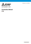
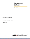
1.3.5
Installing a unit on another unit (Checking the unit installation position)
This section describes the precautions for installing units on another unit.
For the installation method of each unit, refer to the following manual.
GOT2000 Series User's Manual (Hardware)
 When using a bus connection unit
The installation position varies depending on the bus connection unit to be used.
(1) Wide bus units (GT15-75QBUS(2)L, GT15-75ABUS(2)L, GT15-QBUS2, GT15-ABUS2)
Install a bus connection unit in the 1st stage of the extension interface.
If a bus connection unit is installed in the 2nd stage or above, the unit cannot be used.
Example: Installing a bus connection unit and serial communication units
Serial communication unit
Bus connection unit
Bus connection unit
Serial communication unit
(2) Standard size bus connection unit (GT15-QBUS and GT15-ABUS)
A bus connection unit can be installed in any position (1st to 3rd stage) of the extension interface.
Example: Installing a bus connection unit and serial communication units
1 - 14
Serial communication unit
Bus connection unit
Bus connection unit
Serial communication unit
1. PREPARATORY PROCEDURES FOR MONITORING
1.3 Option Devices for the Respective Connection
1
 When using a MELSECNET/H communication unit, CC-Link IE Controller Network
Install a MELSECNET/H communication unit, CC-Link IE Controller Network communication unit, or CC-Link
communication unit in the 1st stage of an extension interface.
If a bus connection unit is installed in the 2nd stage or above, the unit cannot be used.
Example: When installing a MELSECNET/H communication unit and a serial communication unit
Serial communication unit
MELSECNET/H
communication unit
MELSECNET/H
communication unit
Serial communication unit
 When using a serial communication unit
A serial communication unit can be installed in any position (1st to 3rd stage) of the extension interface.
Serial
communication
unit
Serial
communication
unit
 When using the sound output unit or external I/O unit
The sound output unit or external I/O unit can be installed in any position (1st to 3rd stage) of the extension interface.
Example: When installing a sound output unit
Communication
unit
Sound output
unit
Sound output
unit
Communication
unit
1. PREPARATORY PROCEDURES FOR MONITORING
1.3 Option Devices for the Respective Connection
1 - 15
PREPARATORY PROCEDURES FOR MONITORING
communication unit, or CC-Link communication unit (GT15-J61BT13)
 When using the video input unit, RGB input unit, video/RGB input unit, RGB output unit, or
multimedia unit
Install the video input unit, RGB input unit, video/RGB input unit, RGB output unit, or multimedia unit at the 1st stage
of the extension interface. These communication units cannot be used if installed in the 2nd or higher stage.
When any of these units is used, the communication units indicated below must be installed in the 2nd stage of the
extension interface.
Communication unit
Model
Bus connection unit
GT15-QBUS2, GT15-ABUS2
MELSECNET/H communication
unit
GT15-J71LP23-25, GT15-J71BR13
CC-Link IE Controller Network
connection
GT15-J71GP23-SX
CC-Link communication unit
GT15-J61BT13
Example: When installing a video input unit and a MELSECNET/H communication unit
MELSECNET/H
communication unit
Video/RGB
input unit
1 - 16
1. PREPARATORY PROCEDURES FOR MONITORING
1.3 Option Devices for the Respective Connection
Video/RGB
input unit
MELSECNET/H
communication unit
To connect the GOT to a device in the respective connection type, connection cables between the GOT and a device are
necessary.
For cables needed for each connection, refer to each chapter for connection.
1.4.1
GOT connector specifications
The following shows the connector specifications on the GOT side.
Refer to the following table when preparing connection cables by the user.
 RS-232 interface
Use the following as the RS-232 interface and the RS-232 communication unit connector on the GOT. For the GOT
side of the connection cable, use a connector and connector cover applicable to the GOT connector.
(1) Connector specifications
Hardware
GOT
Connector type
Version
GT27
GT23
-
GT15-RS2-9P
-
GT01-RS4-M
-
Connector model
Manufacturer
9-pin D-sub (male)
inch screw fixed type
17LE-23090-27(D4C□)
DDK Ltd.
9-pin D-sub (male)
inch screw fixed type
17LE-23090-27(D3CC)
DDK Ltd.
(2) Connector pin arrangement
GT27, GT15-RS2-9P, GT01-RS4-M
GOT main part connector
see from the front
1
5
6
9
9-pin D-sub (male)
 RS-422/485 interface
Use the following as the RS-422/485 interface and the RS-422/485 communication unit connector on the GOT.
For the GOT side of the connection cable, use a connector and connector cover applicable to the GOT connector.
(1) Connector model
GOT
Connector type
GT27
GT23
GT15-RS4-9S
GT01-RS4-M
Connector model
Manufacturer
9-pin D-sub (female)
M2.6 millimeter screw
fixed type
17LE-13090-27(D2AC)
DDK Ltd.
9-pin D-sub (female)
M2.6 millimeter screw
fixed type
17LE-13090-27(D3AC)
DDK Ltd.
GT15-RS4-TE
-
-
SL-SMT3.5/10/90F BOX
(2) Connector pin arrangement
GT27, GT15-RS4-9P, GT01-RS4-M
GOT main part connector
see from the front
5
9
1
6
9-pin D-sub (female)
1. PREPARATORY PROCEDURES FOR MONITORING
1.4 Connection Cables for the Respective Connection
1 - 17
1
PREPARATORY PROCEDURES FOR MONITORING
1.4 Connection Cables for the Respective Connection
1.4.2
Coaxial cableconnector connection method
The following describes the method for connecting the BNC connector (connector plug for coaxial cable) and the cable.
CAUTION
 Solder the coaxial cable connectors properly.
Insufficient soldering may result in malfunctions.
Components of the BNC connector
Nut
Structure of the coaxial cable
Washer
Gasket
External conductor
Outer sheath Insulating material
Plug shell
Clamp
Internal conductor
Contact
1.
Remove the external sheath of the coaxial cable with
dimensions as shown below.
A
Cable in use
A
Cut this portion of the outer sheath
2.
Clamp
3C-2V
15mm
5C-2V, 5C-2V-CCY
10mm
Pass the nut, washer, gasket, and clamp through the coaxial
cable as shown on the left and loosen the external conductor.
Nut
Washer
Gasket
Insulating material
Internal conductor
3.
C
B
Cut the external conductor, insulting material, and internal
conductor with the dimensions as shown below.
Note that the external conductor should be cut to the same
dimension as the tapered section of the clamp and smoothed
down to the clamp.
Clamp and external
conductor
Solder here
Cable in use
4.
5.
B
C
3C-2V
6 mm
3 mm
5C-2V, 5C-2V-CCY
7 mm
5 mm
Solder the contact to the internal conductor.
Insert the connector assembly shown in ### into the plug
shell and screw the nut into the plug shell.
Precautions for soldering
Note the following precautions when soldering the internal conductor and contact.
• Make sure that the solder does not bead up at the soldered section.
• Make sure there are no gaps between the connector and cable insulator or they do not cut into each other.
• Perform soldering quickly so the insulation material does not become deformed.
1 - 18
1. PREPARATORY PROCEDURES FOR MONITORING
1.4 Connection Cables for the Respective Connection
1.4.3
Terminating resistors of GOT
1
 GT27
Disable
OFF
OFF
1
2
100 OHM
ON
ON
Disable
OFF
OFF
1
ON
SW1
ON
resistor*1
2
100 OHM
O
N
2
1
1
*1
Switch No.
Terminating
resistor*1
SW1
Switch No.
Terminating
Set the terminating resistor using the terminating
resistor setting switch.
The default setting is "Disable".
*1
• For RS422/485 communication unit
2
Set the terminating resistor using the terminating
resistor setting switch.
O
N
 RS-422/485 communication unit
The default setting is "Disable".
• For GT2710-V
1
ON
SW1
2
ON
Terminating resistor setting switch
Rear view of RS-422/485 communication unit.
Terminating resistor setting switch
(inside the cover)
• For GT2310-V
Terminating resistor setting switch
(inside the cover)
1. PREPARATORY PROCEDURES FOR MONITORING
1.4 Connection Cables for the Respective Connection
1 - 19
PREPARATORY PROCEDURES FOR MONITORING
The following shows the terminating resistor specifications on the GOT side.
When setting the terminating resistor in each connection type, refer to the following.
1.5 Verifying GOT Recognizes Connected Equipment
Verify the GOT recognizes controllers on [Communication Settings] of the Utility.
• Channel number of communication interface, communication drivers allocation status
• Communication unit installation status
For details on the Utility, refer to the following manual.
GOT2000 Series User's Manual (Utility)
1.
1.
3.
4.
2.
3.
4.
1 - 20
1. PREPARATORY PROCEDURES FOR MONITORING
1.5 Verifying GOT Recognizes Connected Equipment
After powering up the GOT, touch [GOT basic
set]
[Controller] from the Utility.
The [Communication Settings] appears.
Verify that the communication driver name to
be used is displayed in the communication
interface box to be used.
When the communication driver name is not
displayed normally, carry out the following
procedure again.
1.1Setting the Communication Interface
1
POINT
(1) How to display Utility (at default)
Utility call key
1-point press on GOT screen
upper-left corner
Utility display
(2) Utility call
When setting [Pressing time] to other than 0 second on the setting screen of the utility call key, press and hold
the utility call key until the buzzer sounds. For the setting of the utility call key, refer to the following.
GOT2000 Series User's Manual (Utility)
(3) Communication interface setting by the Utility
The communication interface setting can be changed on the Utility's [Communication setting] after writing
[Communication Settings] of project data.
For details on the Utility, refer to the following manual.
GOT2000 Series User's Manual (Utility)
(4) Precedence in communication settings
When settings are made by GT Designer3 or the Utility, the latest setting is effective.
1. PREPARATORY PROCEDURES FOR MONITORING
1.5 Verifying GOT Recognizes Connected Equipment
1 - 21
PREPARATORY PROCEDURES FOR MONITORING
Utility
1.6 Checking for Normal Monitoring
1.6.1
Check on the GOT
 Check for errors occurring on the GOT
Presetting the system alarm to project data allows you to identify errors occurred on the GOT, PLC CPU, servo
amplifier and communications.
For details on the operation method of the GOT Utility screen, refer to the following manual.
GOT2000 Series User's Manual (Utility)
Error code
Communication Channel No.
Error message
Time of occurrence
(Displayed only for errors)
HINT
Alarm popup display
With the alarm popup display function, alarms are displayed as a popup display regardless of whether an alarm
display object is placed on the screen or not (regardless of the display screen).
Since comments can be flown from right to left, even a long comment can be displayed all.
For details of the alarm popup display, refer to the following manual.
GT Designer3 (GOT2000) Help
1 - 22
1. PREPARATORY PROCEDURES FOR MONITORING
1.6 Checking for Normal Monitoring
1
 Write data to virtual devices inside GOT (For microcomputer connection)
Send a message from the host to the GOT, and confirm that the values are stored in the virtual devices inside the
GOT.
2.7 System Configuration Examples)
PREPARATORY PROCEDURES FOR MONITORING
(
Write command
S
E
T RW 0100 000A 0163 0362 T
X
X
D3
Microcomputer board
1. PREPARATORY PROCEDURES FOR MONITORING
1.6 Checking for Normal Monitoring
1 - 23
1.6.2
Confirming the communication state on the GOT side (For Ethernet
connection)
 Confirming the communication state on Windows®, GT Designer3
(1) When using the Command Prompt of Windows®
Execute a Ping command at the Command Prompt of Windows®.
(a) When normal communication
C:\>Ping 192.168.3.18
Reply from 192.168.3.18: bytes=32 time<1ms TTL=64
(b) When abnormal communication
C:\>Ping 192.168.3.18
Request timed out.
(2) When using the [PING Test] of GT Designer3
Select [Communication]
[Communication configuration]
[Ethernet] and
1.
2.
2.
[Connection Test].
Specify the [GOT IP Address] of the [PING
Test] and click the [PING Test] button.
The [Test Result] is displayed after the [PING
Test] is finished.
Click!
1.
(3) When abnormal communication
At abnormal communication, check the followings and execute the Ping command again.
• Mounting condition of Ethernet communication unit
• Cable connecting condition
• Confirmation of [Communication Settings]
• IP address of GOT specified by Ping command
1 - 24
1. PREPARATORY PROCEDURES FOR MONITORING
1.6 Checking for Normal Monitoring
1
 Confirming the communication state on the GOT
The Ping test can be confirmed by the Utility screen of the GOT.
For the operation method of GOT Utility, refer to the following.
1. PREPARATORY PROCEDURES FOR MONITORING
1.6 Checking for Normal Monitoring
PREPARATORY PROCEDURES FOR MONITORING
GOT2000 Series User's Manual (Utility)
1 - 25
1.6.3
Confirming the communication state to each station (Station monitoring
function)
The station monitoring function detects the faults (communication timeout) of the stations monitored by the GOT. When
detecting the abnormal state, it allocates the data for the faulty station to the GOT special register (GS).
(1) No. of faulty stations
(a) Ethernet connection (Except for Ethernet multiple connection)
Total No. of the faulty CPU is stored.
Device
b15 to b8
b7 to b0
GS230
(00H fixed)
No. of faulty stations
(b) Ethernet multiple connection
Total No. of the faulty connected equipment is stored.
Channel
Device
b15 to b8
b7 to b0
Ch1
GS280
(00H fixed)
No. of faulty stations
Ch2
GS300
(00H fixed)
No. of faulty stations
Ch3
GS320
(00H fixed)
No. of faulty stations
Ch4
GS340
(00H fixed)
No. of faulty stations
POINT
When monitoring GS230 on Numerical Display
When monitoring GS230 on Numerical Display, check [mask processing] with data operation tab as the following.
For the data operation, refer to the following manual.
GT Designer3 (GOT2000) Help
Numerical Display (Data Operation tab)
Set [mask processing] to the upper eight bits (b8
to b15) of GS230 on Numerical Display.
1 - 26
1. PREPARATORY PROCEDURES FOR MONITORING
1.6 Checking for Normal Monitoring
1
(2) Faulty station information
The bit corresponding to the faulty station is set. (0: Normal, 1: Abnormal)
The bit is reset after the fault is recovered.
GS231 bit 0
GS231 bit 1
GS231 bit 2
GS231 bit 3
Device
Station number
b15
b14
b13
b12
b11
b10
b9
b8
b7
b6
b5
b4
b3
b2
b1
GS231
16
15
14
13
12
11
10
9
8
7
6
5
4
3
2
b0
1
GS232
32
31
30
29
28
27
26
25
24
23
22
21
20
19
18
17
GS233
48
47
46
45
44
43
42
41
40
39
38
37
36
35
34
33
GS234
64
63
62
61
60
59
58
57
56
55
54
53
52
51
50
49
GS235
80
79
78
77
76
75
74
73
72
71
70
69
68
67
66
65
GS236
96
95
94
93
92
91
90
89
88
87
86
85
84
83
82
81
GS237
112
111
110
109
108
107
106
105
104
103
102
101
100
99
98
97
GS238
128
127
126
125
124
123
122
121
120
119
118
117
116
115
114
113
(b) For the Ethernet multiple connection or the temperature controller connection
The station number to which each device corresponds changes according to the connection/non
connection with Ethernet.
With Ethernet connection: 1 to 128
With other than Ethernet connection: 0 to 127
Example) With Ethernet connection, when PC No. 100 CPU connecting to Ch3 is faulty, GS327.b3 is set.
The following table shows the case with Ethernet connection.
Device
Station number
Ch1
Ch2
Ch3
Ch4
b15
b14
b13
b12
b11
b10
b9
b8
b7
b6
b5
b4
b3
b2
b1
GS281
GS301
GS321
GS341
16
15
14
13
12
11
10
9
8
7
6
5
4
3
2
b0
1
GS282
GS302
GS322
GS342
32
31
30
29
28
27
26
25
24
23
22
21
20
19
18
17
GS283
GS303
GS323
GS343
48
47
46
45
44
43
42
41
40
39
38
37
36
35
34
33
GS284
GS304
GS324
GS344
64
63
62
61
60
59
58
57
56
55
54
53
52
51
50
49
GS285
GS305
GS325
GS345
80
79
78
77
76
75
74
73
72
71
70
69
68
67
66
65
GS286
GS306
GS326
GS346
96
95
94
93
92
91
90
89
88
87
86
85
84
83
82
81
GS287
GS307
GS327
GS347
112
111
110
109
108
107
106
105
104
103
102
101
100
99
98
97
GS288
GS308
GS328
GS348
128
127
126
125
124
123
122
121
120
119
118
117
116
115
114
113
For details on the GS Device, refer to the following manual.
GT Designer3 Screen Design Manual (Fundamentals) Appendix.2.3 GOT special register (GS)
(3) Network No., station No. notification
The network No. and station No. of the GOT in Ethernet connection are stored at GOT startup.
If connected by other than Ethernet, 0 is stored.
Device
Description
CH1
CH2
CH3
CH4
GS376
GS378
GS380
GS382
Network No. (1 to 239)
GS377
GS379
GS381
GS383
Station No. (1 to 64)
1. PREPARATORY PROCEDURES FOR MONITORING
1.6 Checking for Normal Monitoring
1 - 27
PREPARATORY PROCEDURES FOR MONITORING
(a) Ethernet connection (Except for Ethernet multiple connection)
1.6.4
Check on the PLC
 Read IC tag (For RFID connection)
Read IC tag with a RFID reader/writer and check that the read data are written into the PLC CPU.
Detailed settings including sequence programs, device settings and other settings required for monitoring, refer to
the following manual.
GT Designer3 (GOT2000) Help
1 - 28
1. PREPARATORY PROCEDURES FOR MONITORING
1.6 Checking for Normal Monitoring
MICROCOMPUTER
CONNECTION
2.
MICROCOMPUTER CONNECTION (SERIAL) . . . . . . . . . . 2 - 1
3.
MICROCOMPUTER CONNECTION (ETHERNET). . . . . . . 3 - 1
2
MICROCOMPUTER CONNECTION (SERIAL)
2
MICROCOMPUTER
CONNECTION (SERIAL)
2.
2.1 Microcomputer Connection (Serial) . . . . . . . . . . . . . . . . . . . 2 - 2
2.2 System Configuration . . . . . . . . . . . . . . . . . . . . . . . . . . . . . . 2 - 4
2.3 Connection Diagram . . . . . . . . . . . . . . . . . . . . . . . . . . . . . . 2 - 5
2.4 Device Data Area . . . . . . . . . . . . . . . . . . . . . . . . . . . . . . . . . 2 - 6
2.5 Message Formats. . . . . . . . . . . . . . . . . . . . . . . . . . . . . . . . 2 - 19
2.6 GOT Side Settings . . . . . . . . . . . . . . . . . . . . . . . . . . . . . . . 2 - 73
2.7 System Configuration Examples . . . . . . . . . . . . . . . . . . . . 2 - 75
2.8 Device Range that Can Be Set . . . . . . . . . . . . . . . . . . . . . 2 - 78
2.9 Precautions . . . . . . . . . . . . . . . . . . . . . . . . . . . . . . . . . . . . 2 - 79
2-1
2.
MICROCOMPUTER CONNECTION
(SERIAL)
2.1 Microcomputer Connection (Serial)
The "microcomputer connection (Serial)" is a function by
which data can be written or read from a PC,
microcomputer board, PLC, etc. (hereinafter referred to as
"host") to virtual devices of the GOT.
 Flow of data processing
(1) When reading or writing data
Interrupt output is also available from the GOT to the host.
GOT
Virtual devices inside GOT
Screen data
D0
D0 to 4095
Screen display
D100
000A
Device data area
(Virtual devices)*2
Display(D4 to 9)
04/06/01 18:46:49
D163
0362
4.
Input(D20)
D4095
2.
1254
Write,Read Command
Interrupt
output
1. Request
message
3. Response
message
*1
S
E
T RW 0100 000A 0163 0362 T D3
X
X
*1
Host
Microcomputer board
POINT
Virtual devices inside the GOT
The devices inside the GOT are used in the
microcomputer connection.
(PLC devices are not used)
1.
2.
2.4 Device Data Area
3.
4.
2-2
2. MICROCOMPUTER CONNECTION (SERIAL)
2.1 Microcomputer Connection (Serial)
The host sends a request message (the read/write
command) to the GOT.
The GOT performs a read/write processing to its
virtual devices according to the request from the host.
Upon completion of the processing, the GOT sends a
response message (processing result) to the host.
Creating the following objects on the screen allows
you to use the data read/written to the virtual devices:
• Numerical Display that displays data written by the
write command
• Numerical Input that is used to input data to be
upload to the host
(2) When outputting interrupts
GOT
2
Screen data
1.
Device data area
(virtual devices)*2
Interrupt(D13)
output value1
D13
3139H
MICROCOMPUTER CONNECTION (SERIAL)
Screen display
output value2
31H
39H
2. Interrupt output
*1
(When the number of
interrupt data bytes is 2)
Host
1.
2.
Data are written to the virtual devices for interrupt
output from the touch switches on the GOT.
The GOT sends the written data (interrupt output) to
the host.
*1
2.5 Message Formats
*2
2.4 Device Data Area
2. MICROCOMPUTER CONNECTION (SERIAL)
2.1 Microcomputer Connection (Serial)
2-3
2.2 System Configuration
2.2.1
For the microcomputer connection (serial)
 When connecting one GOT
Communication driver
Host
GOT
Computer
Connection cable
Host
Connection cable
Communication
Type
Max.
distance
RS-232
Differs
according to
host side
specifications
Connection diagram number
GOT
Option device
Model
Number of
connectable
equipment
- (Built into GOT)
RS-232 connection diagram 1)
GT15-RS2-9P
1 GOT for 1 host
- (Built into GOT)
RS-422
Differs
according to
host side
specifications
RS-422 connection diagram 1)
GT15-RS4-9S
2-4
2. MICROCOMPUTER CONNECTION (SERIAL)
2.2 System Configuration
2.3 Connection Diagram
The following diagram shows the connection between the
GOT and the microcomputer.
RS-422 cable
2
 Connection diagram
RS-232 cable
(1) RS-422 connection diagram 1)
 Connection diagram
GOT side
Host side
(1) RS-232 connection diagram 1)
RDA
2
SDA
Example of the case where the DTR/DSR signal is not used
RDB
7
SDB
SDA
1
RDA
SDB
6
RDB
RSA
3
-
RSB
8
-
CSA
4
-
CSB
9
-
SG
5
SHELL
GOT side
Host side
CD
1
FG
RD(RXD)
2
SD(TXD)
SD(TXD)
3
RD(RXD)
ER(DTR)
4
RS(RTS)
SG
5
SG
DR(DSR)
6
CS(CTS)
RS(RTS)
7
-
CS(CTS)
8
-
-
9
ER(DTR)
The polarity A and B in signal names may be reversed
depending on the microcomputer to be used.
Prepare a cable according to the microcomputer to be
used.
Example of the case where the DTR/DSR signal is used
GOT side
POINT
Host side
CD
1
FG
RD(RXD)
2
SD(TXD)
SD(TXD)
3
RD(RXD)
ER(DTR)
4
DR(DSR)
SG
5
SG
DR(DSR)
6
ER(DTR)
RS(RTS)
7
RS(RTS)
CS(CTS)
8
CS(CTS)
-
9
5V
 Precautions when preparing a cable
(2) Cable length
The distance between the GOT and the PLC of
connection diagram 1), 2) and 3) must be 1200 m or
less.
The length of the RS-422 connection diagram 4) or RS422 connection diagram 5) must be 30m or less.
(3) GOT side connector
For the GOT side connector, refer to the following.
1.4.1 GOT connector specifications
 Precautions when preparing a cable
(2) Cable length
The length of the RS-232 cable must be 15m or less.
(3) GOT side connector
For the GOT side connector, refer to the following.
1.4.1 GOT connector specifications
 Connecting terminating resistors
(1) GOT side
Set the terminating resistor setting switch of the GOT
main unit to "Disable".
For the procedure to set the terminating resistor, refer
to the following.
1.4.3 Terminating resistors of GOT
2. MICROCOMPUTER CONNECTION (SERIAL)
2.3 Connection Diagram
2-5
MICROCOMPUTER CONNECTION (SERIAL)
2.3.1
2.3.2
2.4 Device Data Area
The following shows a list of virtual devices inside the GOT available in the microcomputer connection (serial), and the
address specification values for each data format.
The address specification of the virtual devices differs depending on the data format.*1
Virtual device*2
Model
Address specification value
Name
Device
range
(decimal)
Device
type
Format
1, 2
Format
3 to 6
Format
7 to 10
Format
11 to 13
Format
14, 15
D
0 to 4095
Word
0 to 4095
D0 to 4095
D0 to 4095
0000 to 0FFFH
8000 to 9FFFH
2.4.1
R
0 to 4095
Word
4096 to 8191
R0 to 4095
R0 to 4095
1000 to 1FFFH
0000 to 1FFFH
2.4.2
L
0 to 2047
Bit
8192 to 8319
L0 to 2047
L0 to 2047
2000 to 207FH
A000 to A0FFH
2.4.3
M0 to 2047
20FFH
2000 to 20FFH
2.4.4
M
0 to 2047
Bit
8320 to 8447
M0 to 2047
SD0 to 15
2100 to 210FH
SM0 to 63
2110 to 2113H
SD
0 to 15
Word
8448 to 8463
D9000 to
9015
SM
0 to 63
Bit
8464 to 8467
M9000 to
9063
*1
2080 to
2100 to 211FH
Refer to
(3000 to 300DH)*3
2.4.5
2200 to 2207H
2.4.6
For the address specification method for each data format, refer to the following.
2.5 Message Formats
•
•
•
•
•
*2
Formats 1, 2
Formats 3 to 6
Formats 7 to 10
Formats 11 to 13
Formats 14, 15
:
:
:
:
:
GOT-A900 Series microcomputer connection
A compatible 1C frame
QnA compatible 3C/4C frame
Digital Electronics Corporation's memory link method
GOT-F900 Series microcomputer connection
When reusing GOT900 Series project data
• GOT-A900 Series virtual devices (D0 to 2047)
Can be used as they are without changing the assignments.
• GOT-F900 Series virtual devices
Since some of the assigned virtual device values differ as indicated below, change the assignment using device batch edit of
GT Designer3.
Refer to the following manual for device batch edit of GT Designer3.
GT Designer3 (GOT2000) Help
*3
GOT1000 Series virtual devices
GOT-F900 Series virtual devices
D0 to 2047
―
D2048 to 4095
―
R0 to 4095
D0 to 4095
L0 to 2047
―
M0 to 2047
M0 to 2047
SD0 to 15
D8000 to 8015
GD0 to 6
SM0 to 63
M8000 to 8063
Access to SD3 to 9 can also be made by the specification of the addresses (3000 to 300DH) of GD0 to 6 on the GOT-F900 Series.
POINT
Values of virtual devices inside the GOT
When the GOT is turned OFF or reset, values are cleared to their defaults
(bit devices: OFF, word devices: 0).
Values are held in the memory when project data are written to the GOT.
2-6
2. MICROCOMPUTER CONNECTION (SERIAL)
2.4 Device Data Area
2.4.1
D devices
The D devices are word devices into which GOT communication errors, clock data or other information are stored.
The user can also store data using the user area.
2
 List of D devices
Address
Description
Set side
D0 to 2
Unused
―
Communication error status
Stores the communication error details of GOT.
0: Normal
1: Error
b15
–
b8 b7 b6 b5 b4 b3
–
b0
Unused
D3
SIO framing error
SIO parity error
SIO overrun error
Communication timeout
error
Unused
• b4 to 6 turn ON when an SIO error occurs, and turn OFF when an request message from the host is received
successfully after the error occurrence.
• b7 turns ON about 3 seconds after the host side DTR becomes OFF, and turns OFF when transmission is
performed successfully to the host after the error occurrence.
Clock data (year)
b15
–
b8 b7
–
b0
System
D4
Lower 2 digits of calendar
year stored as 2-digit BCD
Unused
Clock data (month)
b15
–
b8 b7
–
b0
D5
Data of months 01 to
12 stored as 2-digit BCD
Unused
Clock data (day)
b15
–
b8 b7
–
b0
D6
Data of days 01 to
31 stored as 2-digit BCD
Unused
(Continued to next page)
2. MICROCOMPUTER CONNECTION (SERIAL)
2.4 Device Data Area
2-7
MICROCOMPUTER CONNECTION (SERIAL)
The following lists the D devices (virtual devices inside the GOT).
(From previous page)
Address
Description
Set side
Clock data (hour)
b15
–
–
b8 b7
b0
D7
Data of hours 00 to
23 stored as 2-digit BCD
Unused
Clock data (minute)
b15
–
–
b8 b7
b0
D8
Data of minutes 00 to
59 stored as 2-digit BCD
Unused
Clock data (second)
System
b15
–
–
b8 b7
b0
D9
Data of seconds 00 to
59 stored as 2-digit BCD
Unused
Clock data (day of week)*1
b15
–
b8 b7
–
b0
Day-of-week data stored as
2-digit BCD
D10
00: Sunday 01: Monday
02: Tuesday 03: Wednesday
04: Thursday 05: Friday
06: Saturday
Unused
D11, D12
Unused
―
(Continued to next page)
*1
2-8
If a wrong day of the week is set by the clock data setting commands, the clock data will differ from the time displayed on the
utility.
Example: When June 1, 2004 (Thursday) is set by the clock data setting command (the actual day of the week is Tuesday),
"04" is stored to D10 although Tuesday (TUE) will be displayed on the utility time display.
2. MICROCOMPUTER CONNECTION (SERIAL)
2.4 Device Data Area
(From previous page)
Address
Description
Set side
Interrupt output
When data are written to D13 and D14 from a GOT touch switch, for example, the data of D13
2
and D14 are transmitted (interrupt output) to the host side.*1*2
The data amount (number of bytes) to be interrupt-output is set at "Interrupt Data Byte" in
2.6.1 Setting communication interface (Communication
D13
• Output value when 1 is set to "Interrupt Data Byte" in "Communication Detail Settings"
D13
Lower 8 bits
1 byte
• Output value when 2 is set to "Interrupt Data Byte" in "Communication Detail Settings"
D13
Upper 8 bits
User
Lower 8 bits
2 bytes
• Output value when 4 is set to "Interrupt Data Byte" in "Communication Detail Settings
"(1) When setting the LH order to [32bit Storage] for the communication detail settings
D14
D13
D14
Upper 8 bits
Lower 8 bits
Upper 8 bits
Lower 8 bits
4 bytes
(2) When setting the HL order to [32bit Storage] for the communication detail settings
D13
Upper 8 bits
D14
Lower 8 bits
Upper 8 bits
Lower 8 bits
4 bytes
D15 to 19
Unused
―
D20 to 2031
User area
User
D2032 to 2034
Unused
―
1-second binary counter
The counter is incremented at 1-second intervals after the GOT is turned ON.
(The time elapsed after GOT is turned ON is stored in 1-second units.)
Data are stored in binary format.
D2035
D2036 to 4095
*1
*2
User area
System
User
After writing data, the interrupt data is output within a period of 1 to 10ms.
When data are written to D13 and D14 from the host side, interrupt output is not performed.
2. MICROCOMPUTER CONNECTION (SERIAL)
2.4 Device Data Area
2-9
MICROCOMPUTER CONNECTION (SERIAL)
"Communication Detail Settings".(
settings))
POINT
(1) The side where virtual devices are set
System : Set on the system side.
User
: Set on the user side (by sending request messages from host or using the touch switches, etc.
on the GOT).
(2) Interrupt output (D13, D14)
• To disable the interrupt output, turn ON SM52 (interrupt code output disable flag). (
2.4.6 SM devices)
• To enable the interrupt output, set 8 bits to the data length at "Communication Detail Settings".
(
2.6.1 Setting communication interface (Communication settings))
• When "7 bits" is set, the MSB (8th bit) is ignored. (Example: FFH 7FH)
 Differences in address specifications by data format
The address specification of devices varies depending on the data format.*1
The following shows the address specification values for each data format.
Address specification value
Model
Address
Format
1, 2
Format
3 to 6
Format
7 to 10
Format
11 to 13
D0
0
D0
D0
0000H
Format
14, 15
8000H
8000H
8001H
8001H
Upper 8 bits
Lower 8 bits
8002H
D1
1
D1
D1
8003H
:
:
:
:
:
D4095
4095
D4095
D4095
0FFFH
*1
2 - 10
:
:
:
:
:
Lower 8 bits
9FFEH
9FFFH
9FFFH
Upper 8 bits
Lower 8 bits
GOT-A900 Series microcomputer connection
A compatible 1C frame
QnA compatible 3C/4C frame
Digital Electronics Corporation's memory link method
GOT-F900 Series microcomputer connection
2. MICROCOMPUTER CONNECTION (SERIAL)
2.4 Device Data Area
Upper 8 bits
9FFEH
2.5 Message Formats
Formats 1, 2
Formats 3 to 6
Formats 7 to 10
Formats 11 to 13
Formats 14, 15
8003H
:
For the address specification method for each data format, refer to the following.
•
•
•
•
•
8002H
0001H
2.4.2
R devices
The R devices are word devices into which user data are stored.
All of these devices can be used as a user area.
2
 List of R devices and differences in address specification by data format
The following shows the R devices (virtual devices inside the GOT).
Address specification value
Model
Address
Format
1, 2
Format
3 to 6
Format
7 to 10
Format
11 to 13
R0
4096
R0
R0
1000H
R1
4097
R1
R1
0000H
0000H
0001H
0001H
Upper 8 bits
Lower 8 bits
0002H
0002H
0003H
0003H
Upper 8 bits
Lower 8 bits
1001H
:
:
:
:
:
R4095
8191
R4095
R4095
1FFFH
*1
Format
14, 15
:
1FFEH
1FFEH
1FFFH
1FFFH
Upper 8 bits
Lower 8 bits
For the address specification method for each data format, refer to the following.
2.5 Message Formats
•
•
•
•
•
Formats 1, 2
:
Formats 3 to 6 :
Formats 7 to 10 :
Formats 11 to 13 :
Formats 14, 15 :
GOT-A900 Series microcomputer connection
A compatible 1C frame
QnA compatible 3C/4C frame
Digital Electronics Corporation's memory link method
GOT-F900 Series microcomputer connection
2. MICROCOMPUTER CONNECTION (SERIAL)
2.4 Device Data Area
2 - 11
MICROCOMPUTER CONNECTION (SERIAL)
The address specification values different depending on the data format are also given below.*1
2.4.3
L devices
The L devices are bit devices into which user data are stored.
All of these devices can be used as a user area.
 List of L devices and differences in address specification by data format
The following shows the L devices (virtual devices inside the GOT).
The address specification values different depending on the data format are also given below.*1
Address
Model
Address specification value
b7
b6
b5
b4
b3
b2
b1
b0
L7
L6
L5
L4
L3
L2
L1
L0
L15
L14
L13
L12
L11
L10
L9
L8
L23
L22
L21
L20
L19
L18
L17
L16
L31
L30
L29
L28
L27
L26
L25
L24
:
L2039
L2038
L2037
L2036
L2035
L2034
L2033
L2032
L2046
L2045
L2044
L2043
L2042
L2041
L2040
Format
3 to 6
Format
7 to 10
8193
8319
Format
11 to 13
2000H
8192
:
L2047
*1
Format
1, 2
Same as address
column on left
2001H
*2
:
207FH
For the address specification method for each data format, refer to the following.
2.5 Message Formats
•
•
•
•
•
*2
2 - 12
Formats 1, 2
Formats 3 to 6
Formats 7 to 10
Formats 11 to 13
Formats 14, 15
:
:
:
:
:
GOT-A900 Series microcomputer connection
A compatible 1C frame
QnA compatible 3C/4C frame
Digital Electronics Corporation's memory link method
GOT-F900 Series microcomputer connection
For reading or writing data in word units, specify the addresses in 16-point units. (Example: L0, L16, L32, etc.)
2. MICROCOMPUTER CONNECTION (SERIAL)
2.4 Device Data Area
Format
14, 15
A000H
A001H
A002H
A003H
:
A0FEH
A0FFH
2.4.4
M devices
The M devices are bit devices into which user data are stored.
All of these devices can be used as a user area.
2
 List of M devices and differences in address specification by data format
The following shows the M devices (virtual devices inside the GOT).
Address
Model
Address specification value
b7
b6
b5
b4
b3
b2
b1
b0
M7
M6
M5
M4
M3
M2
M1
M0
M15
M14
M13
M12
M11
M10
M9
M8
M23
M22
M21
M20
M19
M18
M17
M16
M31
M30
M29
M28
M27
M26
M25
M24
:
M2039
M2038
M2037
M2036
M2035
M2034
M2033
M2032
M2046
M2045
M2044
M2043
M2042
M2041
M2040
Format
3 to 6
Format
7 to 10
8321
Format
11 to 13
2080H
8320
:
M2047
*1
Format
1, 2
Same as address
column on left
*2
8447
2081H
:
20FFH
Format
14, 15
2000H
2H001H
2002H
2003H
:
20FEH
20FFH
For the address specification method for each data format, refer to the following.
2.5 Message Formats
•
•
•
•
•
*2
Formats 1, 2
Formats 3 to 6
Formats 7 to 10
Formats 11 to 13
Formats 14, 15
:
:
:
:
:
GOT-A900 Series microcomputer connection
A compatible 1C frame
QnA compatible 3C/4C frame
Digital Electronics Corporation's memory link method
GOT-F900 Series microcomputer connection
For reading or writing data in word units, specify the addresses in 16-point units.(Example: M0, M16, M32, and others)
2. MICROCOMPUTER CONNECTION (SERIAL)
2.4 Device Data Area
2 - 13
MICROCOMPUTER CONNECTION (SERIAL)
The address specification values different depending on the data format are also given below.*1
2.4.5
SD devices
The SD devices are word devices into which GOT communication errors (error codes), clock data and other information
are stored.
 List of SD devices
The following lists the SD devices (virtual devices inside the GOT).
Address
Description
Set side
100ms counter (32bits)
The counter is incremented at 100ms intervals after GOT is turned ON.
(The time elapsed after GOT is turned ON is stored in 100ms units.)
(1) When setting the LH order to [32bit Storage] for the communication detail settings
The lower and upper bits are stored in SD0 and SD1 respectively.
SD0
SD1
SD1
SD0
Upper word
Lower word
(2) When setting the HL order to [32bit Storage] for the communication detail settings
The upper and lower bits are stored in SD0 and SD1 respectively.
SD0
SD1
Upper word
Lower word
Communication error status
An error data (error code) occurred during communication is stored.
•Host Address (Communication error that occurred on the request destination GOT)
0: No error
1: Parity error
2: Framing error
3: Overrun error
4: Communication message error
5: Command error
6: Clock data setting error
SD2*1
System
•Other station (Communication error that occurred on another GOT when multiple GOTs are connected)
101: Parity error
102: Framing error
103: Overrun error
104: Communication message error
105: Timeout error (No station of the specified address exists.)
106: Multiple units not connectable
107: Clock data setting error
SD3
Clock data (second)
Second data of 00 to 59 is stored.
SD4
Clock data (minute)
Minute data of 00 to 59 is stored.
SD5
Clock data (hour)
Hour data of 00 to 23 is stored.
SD6
Clock data (day)
Day data of 00 to 31 is stored.
SD7
Clock data (month)
Month data of 01 to 12 is stored.
(Continued to next page)
*1
For details and corrective actions for the errors (error codes) that are stored into SD2, refer to the following:
■ Details and actions for errors (error codes) stored into SD2
2 - 14
2. MICROCOMPUTER CONNECTION (SERIAL)
2.4 Device Data Area
(From previous page)
Address
Description
Set side
Clock data (year)
4-digit year data is stored.
2
*1
Clock data (day of week)
Day-of-the-week data is stored.
0: Sunday
1: Monday
4: Thursday
5: Friday
SD9
System
2: Tuesday
6: Saturday
SD10 to 15
3: Wednesday
Unused
*1
―
If a wrong day of the week is set by the clock data setting commands, the clock data will differ from the time displayed on the
utility.
Example: When June 1, 2004 (Thursday) is set by the clock data setting command (the actual day of the week is Tuesday),
"4" is stored to SD9 although Tuesday (TUE) will be displayed on the utility time display.
POINT
The side where virtual devices are set
System
User
: Set on the system side.
: Set on the user side (by sending request messages from host or using the touch switches, etc.
on the GOT).
 Details and actions for errors (error codes) stored into SD2
Error code
0
Description
Action
No error
―
1, 101
Parity error
The parity bit does not match.
2, 102
Framing error
The data bit and/or stop bit are not correct.
3, 103
Overrun error
The next data was transmitted from the host before GOT
completes the processing of the data received.
• Check the settings of "Communication Detail Settings".
• Decrease the transmission speed.
4, 104
Communication message error
EXT/CR could not be found before the upper limit of the
receive buffer was exceeded.
• Check the communication cable and communication module
attachment.
• Check the settings of "Communication Detail Settings".
• Review the contents of the message to transmit.
5
• Check the communication cable and communication module
attachment.
• Check the settings of "Communication Detail Settings".
• Match the GOT and host transmission settings.
• Review the contents of the message to transmit.
• Check the commands in the message.
Command error
An unsupported command was used.
(
2.5.2 List of commands)
105
Timeout error
There is no response from the GOT, or the station of the
specified address does not exist.
• Check the communication cable and communication module
attachment.
• Check the settings of "Communication Detail Settings".
• Review the contents of the message to transmit.
106
Multiple units not connectable
The RS-232 port is occupied.
• Check the communication cable and communication module
attachment.
• Check the settings of "Communication Detail Settings".
• Check to see if the RS-232 port is occupied.
Clock data setting error
The setting value of the clock data has error.
• Review the contents of the message to transmit.
• Check whether the non-existent data is set (e.g. setting "07"
at the day of the week) as clock data.
6, 107
2. MICROCOMPUTER CONNECTION (SERIAL)
2.4 Device Data Area
2 - 15
MICROCOMPUTER CONNECTION (SERIAL)
SD8
 Differences in address specifications by data format
The address specification of devices varies depending on the data format.*1
The following shows the address specification values for each data format.
Address specification value
Address
Formats 1, 2
Formats 3 to 6
Formats 7 to 10
Formats 11 to 13
8448
D9000
SD0
2100H
SD0
SD1
8449
SD2
D9001
8450
SD3
D9002
8451
SD4
D9003
8452
SD5
D9004
8453
SD6
D9005
8454
SD7
D9006
8455
SD8
D9007
8456
SD9
D9008
8457
*1
D9009
SD1
SD2
SD3
SD4
SD5
SD6
SD7
SD8
SD9
Formats 14, 15*2
2100H
2100H
2101H
2101H
Upper 8 bits
Lower 8 bits
2102H
2102H
2103H
2103H
Upper 8 bits
Lower 8 bits
2104H
2104H
2105H
2105H
Upper 8 bits
Lower 8 bits
2106H
(3000H)
2106H(3000H)
2107H(3001H)
Upper 8 bits
Lower 8 bits
2108H(3002H)
2109H(3003H)
Upper 8 bits
Lower 8 bits
210AH(3004H)
210BH(3005H)
Upper 8 bits
Lower 8 bits
210CH(3006H)
210DH(3007H)
Upper 8 bits
Lower 8 bits
210EH(3008H)
210FH(3009H)
Upper 8 bits
Lower 8 bits
2110H(300AH)
2111H(300BH)
Upper 8 bits
Lower 8 bits
2112H(300CH)
2113H(300DH)
Upper 8 bits
Lower 8 bits
2101H
2102H
2103H
2104H
2105H
2106H
2107H
2108H
2109H
2107H
(3001H)
2108H
(3002H)
2109H
(3003H)
210AH
(3004H)
210BH
(3005H)
210CH
(3006H)
210DH
(3007H)
210EH
(3008H)
210FH
(3009H)
2110H
(300AH)
2111H
(300BH)
2112H
(300CH)
2113H
(300DH)
For the address specification method for each data format, refer to the following.
2.5 Message Formats
•
•
•
•
•
*2
2 - 16
Formats 1, 2
Formats 3 to 6
Formats 7 to 10
Formats 11 to 13
Formats 14, 15
:
:
:
:
:
GOT-A900 Series microcomputer connection
A compatible 1C frame
QnA compatible 3C/4C frame
Digital Electronics Corporation's memory link method
GOT-F900 Series microcomputer connection
SD3 to 9 correspond to GD0 to 6 on the GOT-F900 Series.
Access to SD3 to 9 can be also made by the specification of the addresses (3000 to 300DH) of GD0 to 6 on the GOT-F900
Series.
2. MICROCOMPUTER CONNECTION (SERIAL)
2.4 Device Data Area
2.4.6
SM devices
The SM devices are bit devices into which interrupt outputs and clock data that turn ON/OFF at 1-second cycles.
2
 List of SM devices
The following shows the SM devices (virtual devices inside the GOT).
Description
Set side
Interrupt output
When the ON/OFF state of SM0 to 49 is changed by a touch switch on the GOT, for example, the interrupt
codes shown below are transmitted (interrupt output) to the host side.*1*2
The data amount (number of bytes) to be interrupt-output is set at "Interrupt Data Byte" in "Communication
Detail Settings". (
2.6.1 Setting communication interface (Communication settings))
Address
SM0
SM0 to 49
SM1
SM2
SM48
SM49
Event type
Interrupt code
Changed from OFF to ON
50H
Changed from ON to OFF
51H
Changed from OFF to ON
52H
Changed from ON to OFF
53H
Changed from OFF to ON
54H
Changed from ON to OFF
55H
Changed from OFF to ON
B0H
Changed from ON to OFF
B1H
Changed from OFF to ON
B2H
Changed from ON to OFF
B3H
User
1-second cycle clock
Turns ON/OFF at a 1-second cycle.
SM50
0.5
0.5
System
2-second cycle clock
Turns ON/OFF at a 2-second cycle.
SM51
1
1
Interrupt code output disable flag
Enables or disables the output of the interrupt code.
OFF : Interrupt code output enabled ON : Interrupt code output disabled
SM52
User
When set to disable the interrupt code output, no interrupt data are output to the host.
(Relevant devices: D13, D14, SM0 to 49)
SM53 to 63
Unused
*1
*2
―
After the ON/OFF state is changed, the interrupt data is output within a period of 1 to 10 ms.
When the ON/OFF state of SM0 to 49 is changed from the host side, interrupt output is not performed.
POINT
(1) The side where virtual devices are set
System : Set on the system side.
User
: Set on the user side (by sending request messages from host or using the touch switches, etc.
on the GOT).
(2) Interrupt outputs (SM0 to 49)
• To disable the interrupt output, turn ON SM52 (interrupt code output disable flag).(
2.4.6 SM devices)
• To enable the interrupt output, set 8 bits to the data length at "Communication Detail Settings".
(
2.6.1 Setting communication interface (Communication settings))
• When "7 bits" is set, the MSB (8th bit) is ignored. (Example: FFH 7FH)
2. MICROCOMPUTER CONNECTION (SERIAL)
2.4 Device Data Area
2 - 17
MICROCOMPUTER CONNECTION (SERIAL)
Address
 Differences in address specifications by data format
The address specification of devices varies depending on the data format.*1
The following shows the address specification values for each data format.
Address
Model
Address specification value
b7
b6
b5
b4
b3
b2
b1
b0
SM7
SM6
SM5
SM4
SM3
SM2
SM1
SM0
SM15
SM14
SM13
SM12
SM11
SM10
SM9
SM8
SM23
SM22
SM21
SM20
SM19
SM18
SM17
SM16
SM31
SM30
SM29
SM28
SM27
SM26
SM25
SM24
SM39
SM38
SM37
SM36
SM35
SM34
SM33
SM32
SM46
SM45
SM44
SM43
SM42
SM41
SM40
SM52
SM51
SM50
SM49
SM48
SM47
Unused
Unused
*1
Format
1, 2
Format
3 to 6
Format
7 to 10
Format
11 to 13
8464
2110H
8465
2111H
*2*4
8466
8467
―
*3*4
2112H
2113H
For the address specification method for each data format, refer to the following.
2.5 Message Formats
•
•
•
•
•
*2
*3
*4
2 - 18
Formats 1, 2
Formats 3 to 6
Formats 7 to 10
Formats 11 to 13
Formats 14, 15
:
:
:
:
:
GOT-A900 Series microcomputer connection
A compatible 1C frame
QnA compatible 3C/4C frame
Digital Electronics Corporation's memory link method
GOT-F900 Series microcomputer connection
In formats 3 to 6, values are specified within a range of M9000 to 9052.
In formats 7 to 10, values are specified within a range of SM0 to 52.
For reading or writing data in word units, specify the addresses in 16-point units. (Example: SM0, SM16, SM32, etc.)
2. MICROCOMPUTER CONNECTION (SERIAL)
2.4 Device Data Area
Format
14, 15
2200H
2201H
2202H
2203H
2204H
2205H
2206H
―
2.5 Message Formats
This section describes the format of messages that can be used in the microcomputer connection (serial).
Data format type and application
 Data format type and application
Communication is possible using any of the data formats shown below.
(1) Formats 1, 2 (GOT-A900 Series microcomputer connection)
This is the same message format as when a microcomputer connection is established with the GOT-A900
series.
Type
Name
Description
Format 1
GOT-A900 Series microcomputer connection
(format 1)
This format is used when the GOT is connected to the host in a 1:1
connection.
Format 2
GOT-A900 Series microcomputer connection
(format 2)
This is the appended format with error code at the error response of the
GOT-A900 Series microcomputer connection (format 1).
Refer to
2.5.3
(2) Formats 3 to 6 (A compatible 1C frame)
This is the same message format as when communication is performed using the dedicated protocol of the A
series computer link module.
Type
Name
Description
Format 3
A compatible 1C frame (format 1)
This is the basic format of the dedicated protocols.
Format 4
A compatible 1C frame (format 2)
This is the appended format of the A compatible 1C frame (format 1) with a
block No.
Format 5
A compatible 1C frame (format 3)
This is the enclosed format of the A compatible 1C frame (format 1) with
STX and ETX.
Format 6
A compatible 1C frame (format 4)
This is the appended format of the A compatible 1C frame (format 1) with
CR and LF.
Refer to
2.5.4
(3) Formats 7 to 10 (QnA compatible 3C/4C frame)
This is the same message format as when a communication is performed using the MC protocol of Q/QnA
Series serial communication module.
Type
Name
Description
Format 7
QnA compatible 3C/4C frame (format 1)
This is the basic format of the MC protocols.
Format 8
QnA compatible 3C/4C frame (format 2)
This is the appended format of the QnA compatible 3C/4C frame (format 1)
with block No.
Format 9
QnA compatible 3C/4C frame (format 3)
This is the enclosed format of the QnA compatible 3C/4C frame (format 1)
with STX and ETX.
Format 10
QnA compatible 3C/4C frame (format 4)
This is the appended format of the QnA compatible 3C/4C frame (format 1)
with CR and LF.
2. MICROCOMPUTER CONNECTION (SERIAL)
2.5 Message Formats
Refer to
2.5.5
2 - 19
MICROCOMPUTER CONNECTION (SERIAL)
2.5.1
2
(4) Formats 11 to 13 (Digital Electronics Corporation's memory link method)
This is the same format as the protocol of the Digital Electronics Corporation's memory link method.
Type
Name
Description
Format 11
Digital Electronics Corporation's memory link
method
(compatible mode)
This is the basic format of the Digital Electronics Corporation's memory link
method.
Format 12
Digital Electronics Corporation's memory link
method
(extended mode, ASCII code 1:1)
This is the appended format of the Digital Electronics Corporation's memory
link method (compatible mode) with sum check, CR and LF.
Format 13
Digital Electronics Corporation's memory link
method
(extended mode, ASCII code 1:n)
This is the appended format of the Digital Electronics Corporation's memory
link method (extended mode, ASCII code 1:1) with a station No.
Refer to
2.5.6
(5) Formats 14, 15 (GOT-F900 Series microcomputer connection)
This is the same message format as when a microcomputer connection is established with the GOT-F900
Series.
Type
Name
Description
Format 14
GOT-F900 Series microcomputer connection
(format 1)
Use this format when establishing a 1:1 or m:n connection between the
GOT and the host.
The end code is CR.
Format 15
GOT-F900 Series microcomputer connection
(format 2)
Use this format when establishing a 1:1 or m:n connection between the
GOT and the host.
The end code is ETX or sum check.
 How to set data format
Set the data format at [Detail setting] in GT Designer3.
For details of the data format setting method, refer to the following.
2.6.1 Setting communication interface (Communication settings)
2 - 20
2. MICROCOMPUTER CONNECTION (SERIAL)
2.5 Message Formats
Refer to
2.5.7
2.5.2
List of commands
The following shows the list of commands available in each data format.
Command
Command name
Description
Max. number of points
processed
Symbol
ASCII
code
RD
52H 44H
Batch read
in word units
WD
57H 44H
Batch write
in word units
Writes to word devices in 1-point units.
Random read
Reads multiple different bit devices in 16-point units.
64 words (1024 points)
in word units*1
Reads multiple different word devices in 1-point units.
64 points
Random write
Writes to multiple different word devices in 16-point units.
64 words (1024 points)
in word units*1
Writes to multiple different word devices in 1-point units.
64 points
Reads bit devices in 16-point units.
64 words (1024 points)
Reads word devices in 1-point units.
64 points
Writes to bit devices in 16-point units.
64 words (1024 points)
64 points
RR
52H 52H
RW
52H 57H
TR
54H 52H
Read clock data
Reads the clock data of the GOT.
―
TS
54H 53H
Set clock data
Sets the clock data of the GOT.
―
*1
Mixed specification of bit devices and word devices is also possible.
 List of commands for formats 3 to 6 (A compatible 1C frame)
Command
Command name
Description
Max. number of points
processed
Symbol
ASCII
code
BR
JR
42H 52H
4AH 52H
Batch read
in bit units
WR
QR
57H 52H
51H 52H
Batch read
in word units
BW
JW
42H 57H
4AH 57H
Batch write
in bit units
WW
QW
57H 57H
51H 57H
Batch write
in word units
BT
JT
42H 54H
4AH 54H
Test in bit units
(random write)
WT
QT
57H 54H
51H 54H
Test in word units
(random write)
Writes to multiple different bit devices in 16-point units.*3
64 words (1024 points)
Writes to multiple different word devices in 1-point units.
64 points
TR*2
54H 52H
Read clock data
Reads the clock data of the GOT.
―
TS*2
54H 53H
Set clock data
Sets the clock data of the GOT.
―
*2
*3
Reads bit devices in 1-point units.
64 points
Reads bit devices in 16-point units.*3
64 words (1024 points)
Reads word devices in 1-point units.
64 points
Writes to bit devices in 1-point units.
64 points
Writes to bit devices in 16-point units.*3
64 words (1024 points)
Writes to word devices in 1-point units.
64 points
Writes to multiple different bit devices in 1-point units.
64 points
This is a dedicated command of GOT for the microcomputer connection.
Specifies the address of bit devices in 16-point units. (Example: M0, M16, M32, and others)
2. MICROCOMPUTER CONNECTION (SERIAL)
2.5 Message Formats
2 - 21
MICROCOMPUTER CONNECTION (SERIAL)
2
 List of commands for formats 1, 2 (GOT-A900 Series microcomputer connection)
 Command lists for formats 7 to 10 (QnA compatible 3C/4C frame)
Command
Subcommand
0401
0001
Batch read
in bit units
0401
0000
Batch read
in word units
Command name
Description
Reads bit devices in 1-point units.
Max. number of points
processed
64 points
Reads bit devices in 16-point units.*3
64 words (1024 points)
Reads word devices in 1-point units.
64 points
Writes to bit devices in 1-point units.
64 points
1401
0001
Batch write
in bit units
1401
0000
Batch write
in word units
Writes to bit devices in 16-point units.*3
64 words (1024 points)
Writes to word devices in 1-point units.
64 points
Random read
Reads multiple different bit devices in 16-point and 32-point units.*3
in word units*1
Reads multiple different word devices in 1-point and 2-point units.
64 points
Random write
in bit units
Writes to multiple different bit devices in 1-point units.
64 points
Random write
Writes to multiple different bit devices in 16-point and 32-point units.*3
0403
0000
1402
0001
1402
0000
in word units
*1
Writes to multiple different word devices in 1-point and 2-point units.
64 words (1024 points)
64 points
0406
0000
Multiple block
batch read
Reads multiple blocks. A bit device (16 bits for 1 point) or a word device
1406
0000
Multiple block
batch write
Writes multiple blocks. A bit device (16 bits for 1 point) or a word device
1901*2
0000
Read clock data
Reads the clock data of the GOT.
―
0901*2
0000
Set clock data
Sets the clock data of the GOT.
―
*1
*2
*3
(1 word for 1 point) is regarded as one block.*3
64 points
64 points
Mixed specification of bit devices and word devices is also possible.
This is a dedicated command of GOT for the microcomputer connection.
Specifies the address of bit devices in 16-point units. (Example: M0, M16, M32, and others)
 List of commands for formats 11 to 13 (Digital Electronics Corporation's memory link method)
Command
Command name
Description
Max. number of points
processed
Symbol
ASCII
code
R
52H
Batch read
in word units
Reads bit devices in 16-point units.
64 words (1024 points)
Reads word devices in 1-point units.
64 points
W
57H
Batch write
in word units
Writes to bit devices in 16-point units.
64 words (1024 points)
Writes to word devices in 1-point units.
64 points
I
49H
Interrupt inquiry
Issues an interrupt inquiry.(format 13 only)
―
*4
4DH
Read clock data
Reads the clock data of the GOT.
―
M*4
4EH
Set clock data
Sets the clock data of the GOT.
―
N
*4
2 - 22
This is a dedicated command of GOT for the microcomputer connection.
2. MICROCOMPUTER CONNECTION (SERIAL)
2.5 Message Formats
 List of commands for formats 14, 15 (GOT-F900 series microcomputer connection)
Command name
Description
Max. number of points
processed
Symbol
ASCII
code
0
30H
Batch read
(w/out station No.)
Reads bit devices in byte units.
255bytes (2040 points)
Reads word devices in byte units.
255bytes (127 points)
A
41H
Batch read
(w/ station No.)
Reads bit devices in byte units.
255bytes (2040 points)
Reads word devices in byte units.
255bytes (127 points)
1
31H
Batch write
(w/out station No.)
Writes to bit devices in byte units.
255bytes (2040 points)
Writes to word devices in byte units.
255bytes (127 points)
B
42H
Batch write
(w/ station No.)
Writes to bit devices in byte units.
255bytes (2040 points)
Writes to word devices in byte units.
255bytes (127 points)
3
33H
Multi-point write in bit
units (w/out station No.)
44H
Writes bit patterns (bit ON/OFF, inversion, direct specification) in
1-point units (8 bits for 1 point) to a specified device.
70bytes (560 points)
D
Multi-point write in bit
units (w/ station No.)
4
34H
Fill command
(w/out station No.)
E
45H
Fill command
(w/ station No.)
5
35H
Set clock data
(w/out station No.)
F
46H
Set clock data
(w/ station No.)
6
36H
Read clock data
(w/out station No.)
G
47H
Read clock data
(w/ station No.)
Writes the same value to a range of specified devices.
―
Sets the clock data of the GOT.
―
Reads the clock data of the GOT.
―
2. MICROCOMPUTER CONNECTION (SERIAL)
2.5 Message Formats
2 - 23
2
MICROCOMPUTER CONNECTION (SERIAL)
Command
2.5.3
Formats 1, 2 (GOT-A900 Series microcomputer connection)
 Basic format of data communication
Item
Message format
STX
Command
ETX
Data
Sum
Check
Request message
(host
03H
02H
GOT)
(H)
(H)
(L)
(L)
Sum check is performed in this range.
(1) During processing of read commands
STX
ETX
Data
Sum
Check
03H
02H
(H)
Response message
during normal
communication
(GOT
host)
(L)
Sum check is performed in this range.
(2) During processing of write commands
ACK
06H
(format 1: GOT-A900 Series microcomputer connection (format 1))
(format 2: GOT-A900 Series microcomputer connection (format 2))
NAK
NAK Code
15H
15H
Response message
during faulty
communication
(GOT
host)
(format 1: GOT-A900 Series microcomputer connection (format 1))
Error
(format 2: GOT-A900 Series microcomputer connection (format 2))
Output value
During interrupt
output
1/2/4
bytes*1
STX Output value ETX Sum check
02H
1/2/4
bytes*1
03H
(H)
(L)
Sum check is performed in this ran
*1
Set the number of interrupt data bytes at [Detail setting] in GT Designer3.
For the setting of the number of interrupt data bytes, refer to the following.
2.6.1 Setting communication interface (Communication settings)
2 - 24
2. MICROCOMPUTER CONNECTION (SERIAL)
2.5 Message Formats
 Details of data items in message format
POINT
2
Data code during communication
MICROCOMPUTER CONNECTION (SERIAL)
Communication is performed in ASCII code. (excluding interrupt output)
(1) Control codes
Symbol
ASCII code
STX
02H
Start of Text (start marker of message frame)
Description
ETX
03H
End of Text (end marker of message frame)
EOT
04H
End of Transmission
ENQ
05H
Enquiry (start of enquiry)
NAK
15H
Negative ACK (error response)
ACK
06H
Acknowledge (write completion response)
LF
0AH
Line Feed
CL
0CH
Clear
CR
0DH
Carriage Return
(2) Command
Specifies the contents to access from the host to GOT.
The command is converted to a 2-digit ASCII code (Hex) and transmitted from the upper digit.
For details of the commands that can be used, refer to the following.
2.5.2 List of commands
(3) Address
Specifies the head No. of the device data to be read/written.
The address notated in decimal is converted to a 4-digit ASCII code (Hex) and transmitted from the upper digit.
For details of the device range that can be accessed, refer to the following.
2.4 Device Data Area
(4) Number of points
Specifies the number of device data to be read/written. (Setting range: 1 to 64)
The address notated in decimal is converted to a 2-digit ASCII code (Hex) and transmitted from the upper digit.
(5) Year, month, day, hour, minute, second and day of the week data
Specifies year, month, day, hour, minute, second, and day of the week to be read/set to the GOT clock data.
The address notated in decimal is converted to a 2-digit ASCII code (Hex) and transmitted from the upper digit.
■ Message format (5) Read clock data (TR) command
■ Message format (6) Set clock data (TS) command
(6) Data
Specifies the data to read from/write to the specified device data.(word unit)
The address notated in hexadecimal is converted to a 4-digit ASCII code (Hex) and transmitted from the upper
digit.
(7) Error code
This is the response message at faulty communication appended with error contents.
Error code is transmitted in 1 byte.
For details of the error codes generated in format 2 (GOT-A900 Series microcomputer connection (format 2)),
refer to the following:
■ Error code list
2. MICROCOMPUTER CONNECTION (SERIAL)
2.5 Message Formats
2 - 25
(8) Sum check code
The sum check code is obtained by converting the lower 1 byte (8 bits) of the result (sum), after having added
the sum check target data as binary data, to 2-digit ASCII code (Hex).
Number of
points
STX
Command
R
D
0
1
0
0
0
2
02H
52H
44H
30H
31H
30H
30H
30H
32H
(H)
(L)
(H)
(L)
(H)
(L)
Address
ETX
03H
Sum check is performed in this range.
52H + 44H + 30H + 31H + 30H + 30H + 30H + 32H + 03H = 1BCH
2 - 26
2. MICROCOMPUTER CONNECTION (SERIAL)
2.5 Message Formats
Sum
Check
B
C
42H
43H
(H)
(L)
 Message Formats
(1) Batch read in word units (RD) command
(a) When reading a word device
The following shows an example of reading the two points of the virtual devices D100 and D101.
(Assuming D100=0102H, D101=0304H are stored.)
GOT)
D101
0304H
Message format
Number of
points
STX
Command
R
D
0
1
0
0
0
2
02H
52H
44H
30H
31H
30H
30H
30H
32H
(H)
(L)
(H)
(L)
(H)
(L)
Request message
(host
0102H
MICROCOMPUTER CONNECTION (SERIAL)
Item
D100
2
Address
ETX
03H
Sum
Check
B
C
42H
43H
(H)
(L)
Sum check is performed in this range.
STX
Response message
during normal
communication
(GOT
host)
02H
Data 1 (D100)
Data 2 (D101)
ETX
0
1
0
2
0
3
0
4
30H
31H
30H
32H
30H
33H
30H
34H
(L)
(H)
(H)
(L)
03H
Sum
Check
8
D
38H
44H
(H)
(L)
Sum check is performed in this range.
(format 1: GOT-A900 Series microcomputer connection (format 1))
NAK
15H
Response message
during faulty
communication
(GOT
host)
(format 2: GOT-A900 Series microcomputer connection (format 2))
Error
NAK code
15H
06H
The above is a case
where the sum check error
(06H) has occurred.
2. MICROCOMPUTER CONNECTION (SERIAL)
2.5 Message Formats
2 - 27
(b) When reading a bit device
The following shows an example of reading the two points of the virtual devices M0 to M31.
(Assuming M0="1" and M31="1" are stored.
Item
Request message
GOT)
0001H
M31 to 6
8000H
Message format
STX
(host
M15 to 0
02H
Number of
points
Address
Command
R
D
8
3
2
0
0
2
52H
44H
38H
33H
32H
30H
30H
32H
(H)
(L)
(H)
(L)
(H)
(L)
ETX
03H
Sum
Check
C
8
43H
38H
(H)
(L)
Sum check is performed in this range.
STX
Response message
during normal
communication
(GOT
02H
Data 2 (M31 to 16)
Data 1 (M15 to 0)
0
0
0
1
8
0
0
0
30H
30H
30H
31H
38H
30H
30H
30H
(L)
(H)
(H)
ETX
03H
(L)
host)
00000000000000011000000000000000
MMMMMMMMMMMMMMMMMMMMMMMMMMMMMMMM
11111198765432103322222222221111
543210
1098765432109876
(format 1: GOT-A900 Series microcomputer connection (format 1))
NAK
15H
Response message
during faulty
communication
(GOT
(format 2: GOT-A900 Series microcomputer connection (format 2))
host)
Error
NAK code
15H
06H
The above is a case where
the sum check error (06H)
has occurred.
2 - 28
2. MICROCOMPUTER CONNECTION (SERIAL)
2.5 Message Formats
Sum
Check
8
C
38H
43H
(H)
(L)
(2) Batch write in word units (WD) command
(a) When writing to a word device
The following shows as example of writing "0064H"and "0065H"to virtual devices D100 and D101.
D100
0000H
D100
0064H
D101
0000H
D101
0065H
Before execution
After execution
Item
Message format
Command
W
D
0
1
0
0
0
2
0
0
6
4
0
0
6
5
02H
57H
44H
30H
31H
30H
30H
30H
32H
30H
30H
36H
34H
30H
30H
36H
35H
(H)
(L)
(H)
(L)
(H)
(L)
(H)
(L)
(H)
Request message
(host
GOT)
Number of
points
STX
Address
Data 1(D100)
ETX
Data 2 (D101)
(L)
03H
Sum
Check
5
6
35H
36H
(H)
(L)
Sum check is performed in this range.
Response message
during normal
communication
ACK
(GOT
06H
host)
(format 1: GOT-A900 Series microcomputer connection (format 1))
NAK
15H
Response message
during faulty
communication
(GOT
host)
(format 2: GOT-A900 Series microcomputer connection (format 2))
Error
NAK code
15H
06H
The above is a case where
the sum check error (06H)
has occurred.
2. MICROCOMPUTER CONNECTION (SERIAL)
2.5 Message Formats
2 - 29
MICROCOMPUTER CONNECTION (SERIAL)
2
(b) When writing to a bit device
The following shows an example of writing "1"s to virtual devices M0 and M31.
M15 to 0
0000H
M15 to 0
0001H
M31 to 16
0000H
M31 to 16
8000H
Before execution
After execution
Item
Message format
Sum check is performed in this range.
Request message
(host
GOT)
Number
of points
STX
Command
W
D
8
3
2
0
0
2
0
0
0
1
8
0
0
0
02H
57H
44H
38H
33H
32H
30H
30H
32H
30H
30H
30H
31H
38H
30H
30H
30H
(H)
(L)
(H)
–
–
(L)
(H)
(L)
(H)
–
–
(L)
(H)
–
–
(L)
Address
Data 1 (M15 to 0)
Data 2 (M31 to 16)
ETX
03H
00000000000000011000000000000000
MMMMMMMMMMMMMMMMMMMMMMMMMMMMMMMM
11111198765432103322222222221111
543210
1098765432109876
ACK
Response message
during normal
communication
(GOT
06H
host)
(format 1: GOT-A900 Series microcomputer connection (format 1))
NAK
15H
Response message
during faulty
communication
(GOT
host)
(format 2: GOT-A900 Series microcomputer connection (format 2))
Error
NAK code
15H
06H
The above is a case where
the sum check error (06H)
has occurred.
2 - 30
2. MICROCOMPUTER CONNECTION (SERIAL)
2.5 Message Formats
Sum
Check
5
6
35H
36H
(H)
(L)
(3) Random read in word units (RR) command
The following shows an example of reading the two points of the virtual devices D100 and M0 to M15.
(Assuming D100=0064H, M0=1are stored.)
Item
GOT)
M15 to 0
0001H
Message format
STX
Command
R
R
0
1
0
0
8
3
2
0
02H
52H
52H
30H
31H
30H
30H
38H
33H
32H
30H
(H)
(L)
(H)
–
–
(L)
(H)
–
–
(L)
Request message
(host
0064H
MICROCOMPUTER CONNECTION (SERIAL)
2
D100
Address 1
Sum
Check
ETX
Address 2
03H
3
5
33H
35H
(H)
(L)
Sum check is performed in this range.
STX
Response message
during normal
communication
(GOT
02H
Data 2 (M15 to 0)
Data 1 (D100)
0
0
6
4
0
0
0
1
30H
30H
36H
34H
30H
30H
30H
31H
(H)
–
–
(L)
(H)
–
–
(L)
ETX
03H
Sum
Check
8
E
38H
45H
(H)
(L)
host)
0000000000000001
MMMMMMMMMMMMMMMM
1111119876543210
543210
(format 1: GOT-A900 Series microcomputer connection (format 1))
NAK
15H
Response message
during faulty
communication
(GOT
host)
(format 2: GOT-A900 Series microcomputer connection (format 2))
Error
NAK code
15H
06H
The above is a case where
the sum check error (06H)
has occurred.
2. MICROCOMPUTER CONNECTION (SERIAL)
2.5 Message Formats
2 - 31
(4) Random write in word units (RW) command
The following shows an example of writing "0064H" and "1" to virtual devices D100 and M0, respectively.
D100
0000H
D100
0064H
M15 to 0
0000H
M15 to 0
0001H
Before execution
After execution
Item
Message format
STX
Command
R
W
02H
52H
57H
(H)
(L)
ETX
Following*1
03H
Sum
Check
C
5
43H
35H
(H)
(L)
Sum check is performed in this range.
Request message
(host
*1
Address 1
GOT)
Data 1 (D100)
Data 2 (M15 to 0)
Address 2
0
1
0
0
0
0
6
4
8
3
2
0
0
0
0
1
30H
31H
30H
30H
30H
30H
36H
34H
38H
33H
32H
30H
30H
30H
30H
31H
(H)
–
–
(L)
(H)
–
–
(L)
(H)
–
–
(L)
(H)
–
–
(L)
0000000000000001
MMMMMMMMMMMMMMMM
1111119876543210
543210
Response message
during normal
communication
(GOT
ACK
06H
host)
(format 1: GOT-A900 Series microcomputer connection (format 1))
NAK
15H
Response message
during faulty
communication
(GOT
host)
(format 2: GOT-A900 Series microcomputer connection (format 2))
Error
NAK code
15H
06H
The above is a case where
the sum check error (06H)
has occurred.
2 - 32
2. MICROCOMPUTER CONNECTION (SERIAL)
2.5 Message Formats
(5) Read clock data (TR) command
The following shows an example of reading the clock data of GOT.
(Assuming that the clock data of GOT has been set to "2004, June 1, 18:46:49, Tuesday".)
2
Time display
2004/06/01 18:46:49
Message format
STX
Command
T
R
02H
54H
52H
(H)
(L)
Request message
(host
MICROCOMPUTER CONNECTION (SERIAL)
Item
TUE
GOT)
ETX
03H
Sum
Check
A
9
41H
39H
(H)
(L)
Sum check is performed in this range.
Response message
during normal
communication
(GOT
host)
Second
data
Day-ofweek data
STX
Year data Month data
0
4
0
6
0
1
1
8
4
6
4
9
0
2
02H
30H
34H
30H
36H
30H
31H
31H
38H
34H
36H
34H
39H
30H
32H
(H)
(L)
(H)
(L)
(H)
(L)
(H)
(L)
(H)
(L)
(H)
(L)
(H)
(L)
Day data
Hour data Minute data
ETX
03H
Sum
Check
D
0
44H
30H
(H)
(L)
Sum check is performed in this range.
(format 1: GOT-A900 Series microcomputer connection (format 1))
NAK
15H
Response message
during faulty
communication
(GOT
(format 2: GOT-A900 Series microcomputer connection (format 2))
host)
Error
NAK code
15H
06H
The above is a case where
the sum check error (06H)
has occurred.
2. MICROCOMPUTER CONNECTION (SERIAL)
2.5 Message Formats
2 - 33
(6) Set clock data (TS) command
The following shows an example of setting the clock data of GOT.
(Assuming the clock data of GOT is to be set to "2004, June 1, 18:46:49 Tuesday".)
Time display
2004/06/01 18:46:49
TUE
After execution
Item
Message format
GOT)
Day-ofweek data ETX
Command
T
S
0
4
0
6
0
1
1
8
4
6
4
9
0
2
02H
54H
53H
30H
34H
30H
36H
30H
31H
31H
38H
34H
36H
34H
39H
30H
32H
(H)
(L)
(H)
(L)
(H)
(L)
(H)
(L)
(H)
(L)
(H)
(L)
(H)
(L)
(H)
(L)
Request message
(host
Second
data
STX
Year data
Month data
Day data
Hour data Minute data
03H
Sum
Check
7
7
37H
37H
(H)
(L)
Sum check is performed in this range.
Response message
during normal
communication
(GOT
ACK
06H
host)
(format 1: GOT-A900 Series microcomputer connection (format 1))
NAK
15H
Response message
during faulty
communication
(GOT
(format 2: GOT-A900 Series microcomputer connection (format 2))
host)
Error
NAK code
15H
06H
The above is a case where
the sum check error (06H)
has occurred.
POINT
When a wrong day of the week has been set by the clock data setting command
If a wrong day of the week is set by the clock data setting commands, the clock data will differ from the time
displayed on the utility.
Example: When June 1, 2004 (Thursday) is set by the clock data setting command (the actual day of week is
Tuesday), Tuesday (TUE) will be displayed on the utility time display.
2 - 34
2. MICROCOMPUTER CONNECTION (SERIAL)
2.5 Message Formats
(7) In the case of interrupt outputs
The following shows an example of an interrupt output when data are written to the interrupt output devices (D13
and D14).
(Assuming that "3139H" is written to D13 and "AA55H" to D14.)
Example: When the number of interrupt data bytes is 2
3139H
MICROCOMPUTER CONNECTION (SERIAL)
D13
Interrupt
Interrupt output
Output Output
value 1 value 2
31H
Item
39H
Message format
(1) When [Interrupt Data Byte] in "Communication Detail Settings" is set to "1 byte"
(format 1: in the case of GOT-A900 Series
microcomputer connection
(format 1))
Output
value 1
(format 2: in the case of GOT-A900 Series
microcomputer connection
(format 2))
STX Output
value 1 ETX Sum check
02H
39H
39H
03H
3
C
33H
43H
(H)
(L)
Sum check is performed in this range.
(2) When [Interrupt Data Byte] in "Communication Detail Settings" is set to "2 byte"
(format 1: in the case of GOT-A900 Series
microcomputer connection
(format 1))
Interrupt output
(GOT
Output Output
value 1 value 2
(format 2: in the case of GOT-A900 Series
microcomputer connection
(format 2))
Output
STX Output
value 1 value 2 ETX Sum check
host)
31H
39H
02H
31H
39H
03H
6
D
36H
44H
(H)
(L)
Sum check is performed in this range.
(3) When [Interrupt Data Byte] in "Communication Detail Settings" is set to "4 byte"
(format 1: in the case of GOT-A900 Series
microcomputer connection
(format 1))
Output Output Output Output
value1 value2 value3 value4
AAH
55H
31H
39H
(format 2: in the case of GOT-A900 Series
microcomputer connection
(format 2))
Output Output Output Output
STX value1 value2 value3 value4 ETX
02H
AAH
55H
31H
39H
03H
2
Sum
Check
6
C
36H
43H
(H)
(L)
Sum check is performed in this range.
2. MICROCOMPUTER CONNECTION (SERIAL)
2.5 Message Formats
2 - 35
POINT
Interrupt output
• To disable the interrupt output, turn ON SM52 (interrupt code output disable flag). (
2.4.6 SM devices)
• To enable the interrupt output, set 8 bits to the data length at "Communication Detail Settings".
(
2.6.1 Setting communication interface (Communication settings))
• When "7 bits" is set, the MSB (8th bit) is ignored. (Example: FFH 7FH)
 Error code list
In the case of format 2 (GOT-A900 series microcomputer connection (format 2)), the error contents (error code) are
appended to the response message during faulty communication.
The following shows error code, error contents, cause, and measures.
Error code
Description
06H
Sum check error
The sum check code created from received data differs
from the sum check code in the receive data.
10H
Command error
An unsupported command was used.
Action
• Review the contents of the message to transmit.
• Check the commands in the message.
(
2.5.2 List of commands)
11H
Message length error
The upper limit of the data length that can be received by
the GOT has been exceeded.
• Review the contents of the message to transmit.
• Check the data length of the message.(data length of the data section,
etc.)
12H
Communication message error
EXT was not found within the upper limit of the receive
buffer.
• Check the communication cable and communication module attachment.
• Check the settings of "Communication Detail Settings".
• Review the contents of the message to transmit.
15H
Clock data setting error
The setting value of the clock data has error.
• Review the contents of the message to transmit.
• Check whether the non-existent data is set (e.g. setting "07" at the day of
the week) as clock data.
7AH
Address error
The start address of the read/write device is out of range.
7BH
Exceeded number of points error
The read/write range exceeded the device range.
• Review the contents of the message to transmit.
• Check the devices that can be used and the device ranges.
(
2.4 Device Data Area)
 Precautions
(1) Batch reading/writing crossing over different devices
When using the batch read (RD) or batch write (WD) command, do not batch read/write crossing over the
different devices.
This will cause an error response.
(2) Storage order for 32-bit data
To use the program of GOT-A900 series with [32bit Order] setting to GOT1000 series, set [HL Order] to [32bit
Order] for [Communication Detail Settings] when 32-bit data is set for GOT-A900 series.
With setting [LH Order], the order of upper bits and lower bits are reversed when the GOT displays and writes
32-bit data.
2 - 36
2. MICROCOMPUTER CONNECTION (SERIAL)
2.5 Message Formats
2.5.4
Formats 3 to 6 (A compatible 1C frame)
 Basic format of data communication
This is the same message format as when communication is performed using the dedicated protocol (A compatible
1C frame) of the A Series computer link module.
For details of the basic format of data communication, refer to the following manual:
2
This section describes items whose settings differ from the dedicated protocol of the A Series computer link modules,
and the dedicated commands for a GOT microcomputer connection.
Example: Request message for the batch read in word units (QR) command in format 4 (A compatible 1C frame
(format 2))
Character A section
ENQ
05H
Station
No.
Block No.
PLC No.
Command Wait
Number
of points
Address
Sum
Check
0
0
0
0
0
0
Q
R
0
D
0
0
0
1
0
0
0
2
B
A
30H
30H
30H
30H
30H
30H
51H
52H
30H
44H
30H
30H
30H
31H
30H
30H
30H
32H
42H
41H
(H)
(L)
(H)
(L)
(H)
(L)
(H)
(L)
(H)
–
–
–
–
–
(L)
(H)
(L)
(H)
(L)
Sum check is performed in this range.
 Details of data items in message format
POINT
Data code during communication
Communication is performed in ASCII code.
(1) Block No, PLC No.
Ignored in a microcomputer connection of the GOT.
Specify "00".
"00" is converted to a 2-digit ASCII code (Hex) and transmitted from the upper digit.
(2) Station No.
Station No. is used to identify the GOT with which the host communicates. (Setting range: 0 to 31)
The address notated in decimal is converted to a 2-digit ASCII code (Hex) and transmitted from the upper digit.
The GOT processes only commands whose station No. matches the "Host Address (0 to 31)" set at
"Communication Detail Settings". (The message of command whose station No. does not match is ignored.)
For setting method of "Communication Detail Settings", refer to the following.
2.6.1 Setting communication interface (Communication settings)
(3) Command
Specifies the contents to access from the host to GOT.
The command is converted to a 2-digit ASCII code (Hex) and transmitted from the upper digit.
For details of the commands that can be used, refer to the following.
2.5.2 List of commands
2. MICROCOMPUTER CONNECTION (SERIAL)
2.5 Message Formats
2 - 37
MICROCOMPUTER CONNECTION (SERIAL)
MELSEC-Q/L MELSEC Communication Protocol Reference Manual
(4) Address
Specifies the head No. of the device data to be read/written.
The data annotated in decimal is converted to a 5- or 7-digit ASCII code (Hex) and transmitted from the upper
digit.
For details of the device range that can be accessed, refer to the following.
2.4 Device Data Area
(5) Number of points
Specifies the number of device data to be read/written. (Setting range: 1 to 40H)
The address notated in hexadecimal is converted to a 2-digit ASCII code (Hex) and transmitted from the upper
digit.
(6) Year, month, day, hour, minute, second and day of the week data
Specifies year, month, day, hour, minute, second, and day of the week to be read/set to the GOT clock data.
The address notated in decimal is converted to a 2-digit ASCII code (Hex) and transmitted from the upper digit.
■ (1) Read clock data (TR) command
■ (2) Set clock data (TS) command
(7) Error code
This is the response message at faulty communication appended with error contents.
The address notated in hexadecimal is converted to a 2-digit ASCII code (Hex) and transmitted from the upper
digit.
For details of error codes generated in formats 3 to 6 (A compatible 1C frame), refer to the following:
■ Error code list
POINT
When connecting a microcomputer, etc. that uses the dedicated protocol of the A series computer link module with
the GOT
When connecting a microcomputer, etc. that uses the dedicated protocol of the A series computer link module with
the GOT, correct the commands to use and the device range according to the specifications of GOT.
2 - 38
2. MICROCOMPUTER CONNECTION (SERIAL)
2.5 Message Formats
 Message format
The following shows the message format of the dedicated commands for a microcomputer connection of GOT.
(1) Read clock data (TR) command
2
MICROCOMPUTER CONNECTION (SERIAL)
The following shows an example of reading the clock data of GOT.
(Assuming that the clock data of GOT has been set to "2004, June 1, 18:46:49, Tuesday".)
Time display
2004/06/01 18:46:49
Item
TUE
Message format
Example: Format 3 (A compatible 1C frame (format 1))
PLC No.
ENQ Station No.
Request message
(host
GOT)
05H
Sum
Check
Command Wait
0
0
0
0
T
R
0
9
6
30H
30H
30H
30H
54H
52H
30H
39H
36H
(H)
(L)
(H)
(L)
(H)
(L)
(H)
(L)
Sum check is performed in this range.
Example: Format 3 (A compatible 1C frame (format 1))
Character B section
STX Station No.
02H
Response message
during normal
communication
(GOT
ETX
PLC No.
0
0
0
0
30H
30H
30H
30H
(H)
(L)
(H)
(L)
Following*1
03H
Sum
Check
9
0
39H
30H
(H)
(L)
Sum check is performed in this range.
host)
*1
Year data Month data
Day data
Hour data
Minute
data
Second
data
Day-ofweek data
0
4
0
6
0
1
1
8
4
6
4
9
0
2
30H
34H
30H
36H
30H
31H
31H
38H
34H
36H
34H
39H
30H
32H
(H)
(L)
(H)
(L)
(H)
(L)
(H)
(L)
(H)
(L)
(H)
(L)
(H)
(L)
Example: Format 3 (A compatible 1C frame (format 1))
Response message
during faulty
communication
(GOT
host)
NAK Station No.
15H
PLC No.
Error code
0
0
0
0
0
5
30H
30H
30H
30H
30H
35H
(H)
(L)
(H)
(L)
(H)
(L)
The above is the case where an
overrun error (05H) has occurred.
2. MICROCOMPUTER CONNECTION (SERIAL)
2.5 Message Formats
2 - 39
(2) Set clock data (TS) command
The following shows an example of setting the clock data of GOT.
(Assuming the clock data of GOT is to be set to "2004, June 1, 18:46:49 Tuesday".)
Time display
2004/06/01 18:46:49
TUE
After execution
Item
Message format
Example: Format 3 (A compatible 1C frame (format 1))
Character C section
ENQ Station No.
05H
Request message
(host
Following*1
0
0
0
0
T
S
0
30H
30H
30H
30H
54H
53H
30H
(H)
(L)
(H)
(L)
(H)
(L)
GOT)
Sum
Check
Command Wait
PLC No.
6
4
36H
34H
(H)
(L)
Sum check is performed in this range.
*1
Year data
Month data
Day data
Second
data
Hour data Minute data
Day-ofweek data
0
4
0
6
0
1
1
8
4
6
4
9
0
2
30H
34H
30H
36H
30H
31H
31H
38H
34H
36H
34H
39H
30H
32H
(H)
(L)
(H)
(L)
(H)
(L)
(H)
(L)
(H)
(L)
(H)
(L)
(H)
(L)
Example: Format 3 (A compatible 1C frame (format 1))
Response message
during normal
communication
(GOT
ACK Station No.
host)
06H
PLC No.
0
0
0
0
30H
30H
30H
30H
(H)
(L)
(H)
(L)
Example: Format 3 (A compatible 1C frame (format 1))
NAK Station No.
Response message
during faulty
communication
(GOT
15H
host)
PLC No.
Error code
0
0
0
0
0
5
30H
30H
30H
30H
30H
35H
(H)
(L)
(H)
(L)
(H)
(L)
The above is the case where an
overrun error (05H) has occurred.
POINT
When a wrong day of the week has been set by the clock data setting command
If a wrong day of the week is set by the clock data setting commands, the clock data will differ from the time
displayed on the utility.
Example: When June 1, 2004 (Thursday) is set by the clock data setting command (the actual day of week is
Tuesday), Tuesday (TUE) will be displayed on the utility time display.
2 - 40
2. MICROCOMPUTER CONNECTION (SERIAL)
2.5 Message Formats
 Error code list
The following shows error code, error contents, cause, and measures.
Description
2
Action
01H
Parity error
The parity bit does not match.
• Check the communication cable and communication module attachment.
• Check the settings of "Communication Detail Settings".
• Match the GOT and host transmission settings.
02H
Sum check error
The sum check code created from received data differs
from the sum check code in the receive data.
• Review the contents of the message to transmit.
03H
Protocol error
Received a message that does not follow the control
procedure of the format set at "Communication Detail
Settings".
• Check the settings of "Communication Detail Settings".
• Review the contents of the message to transmit.
05H
Overrun error
The next data was transmitted from the host before GOT
completes the processing of the data received.
• Check the settings of "Communication Detail Settings".
• Decrease the transmission speed.
06H
Character section error
The character section specification error.
•The method of specifying the character section is wrong.
•The specified command has error.
•The number of points of the processing requests exceeds
the allowable range.
•A non-existent device has been specified.
•The setting value of the clock data has error.
07H
Character error
A character other than "A to Z", "0 to 9", space, and control
codes has been received.
• Review the contents of the message to transmit.
• Check the commands in the message.
(
2.5.2 List of commands)
• Check the devices that can be used and the device ranges.
(
2.4 Device Data Area)
• Check whether the non-existent data is set (e.g. setting "07" at the day of
the week) as clock data.
• Review the contents of the message to transmit.
2. MICROCOMPUTER CONNECTION (SERIAL)
2.5 Message Formats
2 - 41
MICROCOMPUTER CONNECTION (SERIAL)
Error code
2.5.5
Formats 7 to 10 (QnA compatible 3C/4C frame)
 Basic format of data communication
This is the same message format as when communication is performed using the MC protocol (QnA compatible 3C/
4C frame) of the Q/QnA Series serial communication module.
For details of the basic format of data communication, refer to the following manual:
MELSEC-Q/L MELSEC Communication Protocol Reference Manual
This section describes items whose settings differ from the MC protocol of the Q/QnA Series serial communication
module, and the dedicated commands for a GOT microcomputer connection.
Example: Request message for the batch read in word units (0401) command in format 8 (QnA compatible 4C frame
(format 2))
Frame ID
No.
ENQ Block No.
05H
Station No.
Network
No.
PLC No.
Request destination
module I/O No.
Request destination Host Address
module station No. No.
Sum check
Following
*1
0
0
F
8
0
0
0
0
0
0
0
0
0
0
0
0
0
0
B
A
30H
30H
46H
38H
30H
30H
30H
30H
30H
30H
30H
30H
30H
30H
30H
30H
30H
30H
42H
41H
(H)
(L)
(H)
(L)
(H)
(L)
(H)
(L)
(H)
(L)
(H)
–
–
(L)
(H)
(L)
(H)
(L)
(H)
(L)
Sum check is performed in this range.
Character A section
*1
Command
Device
code
Sub-command
0
4
0
1
0
0
0
0
D
*
0
0
0
1
0
0
0
0
0
2
30H
34H
30H
31H
30H
30H
30H
30H
44H
2AH
30H
30H
30H
31H
30H
30H
30H
30H
30H
32H
(H)
–
–
(L)
(H)
–
–
(L)
(H)
(L)
(H)
–
–
–
–
(L)
(H)
–
–
(L)
POINT
QnA compatible 4C frame (format 5)
GOT cannot use the QnA compatible 4C frame (format 5).
2 - 42
Device points
Head Device
2. MICROCOMPUTER CONNECTION (SERIAL)
2.5 Message Formats
 Details of data items in message format
POINT
2
Data code during communication
(1) Block No., network No., PLC No., request destination module I/O No. and station No.
Ignored in a microcomputer connection of the GOT.
Specify "00". (The request destination module I/O No. is "0000".)
"00" is converted to a 2-digit ASCII code (Hex) and transmitted from the upper digit.
(The request destination module I/O No. is 4-digit.)
(2) Station No.
Station No. is used to identify the GOT with which the host communicates.(Setting range: 0 to 1FH)
The address notated in hexadecimal is converted to a 2-digit ASCII code (Hex) and transmitted from the upper
digit.
The GOT processes only commands whose station No. matches the "Host Address (0 to 31)" set at
"Communication Detail Settings". (The message of command whose station No. does not match is ignored.)
For setting method of "Communication Detail Settings", refer to the following.
2.6.1 Setting communication interface (Communication settings)
(3) Command, sub-command
Specifies the contents to access from the host to GOT.
The command is converted to a 4-digit ASCII code (Hex) and transmitted from the upper digit.
For details of the commands that can be used, refer to the following.
2.5.2 List of commands
(4) Device code
Specifies the code by which the device data to be read/written is recognized.
The command is converted to a 2-digit ASCII code (Hex) and transmitted from the upper digit.
For details of the device range that can be accessed, refer to the following.
2.4 Device Data Area
(5) Head device
Specifies the head No. of the device data to be read/written.
The address notated in decimal is converted to a 6-digit ASCII code (Hex) and transmitted from the upper digit.
For details of the device range that can be accessed, refer to the following.
2.4 Device Data Area
(6) Device points
Specifies the number of device data to be read/written. (Setting range: 1 to 40H)
The address notated in hexadecimal is converted to a 2-digit ASCII code (Hex) and transmitted from the upper
digit.
When specifying multiple devices as follows, limit the total device points to within 64 points.
(a) When using random read/write command
When setting multiple bit accesses, word accesses or double word accesses, limit the total number of
access points to within 64 points
(b) When using multiple block batch read/write commands
When setting multiple blocks, limit the total number of points of all blocks to within 64 points.
2. MICROCOMPUTER CONNECTION (SERIAL)
2.5 Message Formats
2 - 43
MICROCOMPUTER CONNECTION (SERIAL)
Communication is performed in ASCII code.
(7) Year, month, day, hour, minute, second and day of the week data
Specifies year, month, day, hour, minute, second, and day of the week to be read/set to the GOT clock data.
The address notated in decimal is converted to a 2-digit ASCII code (Hex) and transmitted from the upper digit.
■ Message format (1) Read clock data (1901) command
■ Message format (2) Set clock data (0901) command
(8) Error code
This is the response message at faulty communication appended with error contents.
The address notated in hexadecimal is converted to a 4-digit ASCII code (Hex) and transmitted from the upper
digit.
For details of error codes that are generated in formats 7 to 10 (QnA compatible 3C/4C frame), refer to the
following:
■ Error code list
POINT
When connecting a microcomputer, etc. that uses the MC protocol of the Q/QnA series serial communication
module with the GOT
When connecting a microcomputer, etc. that uses the MC protocol of the Q/QnA series serial communication
module with the GOT, correct the commands to be used and the device ranges to match the GOT specifications.
2 - 44
2. MICROCOMPUTER CONNECTION (SERIAL)
2.5 Message Formats
 Message format
The following shows the message format of the dedicated commands for a microcomputer connection of GOT.
(1) Read clock data (1901) command
2
MICROCOMPUTER CONNECTION (SERIAL)
The following shows an example of reading the clock data of GOT.
(Assuming that the clock data of GOT has been set to "2004, June 1, 18:46:49, Tuesday".)
Time display
2004/06/01 18:46:49
Item
TUE
Message format
Example: Format 7 (QnA compatible 4C frame (format 1))
ENQ
05H
Frame ID
No.
Station No.
Network
No.
Request destination
module station No.
F
8
0
0
0
0
0
0
0
0
0
0
0
0
46H
38H
30H
30H
30H
30H
30H
30H
30H
30H
30H
30H
30H
30H
(H)
(L)
(H)
(L)
(H)
(L)
(H)
(L)
(H)
–
–
(L)
(H)
(L)
Request message
(host
Request destination
module I/O No.
PLC No.
Sum check
Following
*1
A
9
41H
39H
(H)
(L)
Sum check is performed in this range.
GOT)
Character A section
*1
Host
Address No.
Command
Sub-command
0
0
1
9
0
1
0
0
0
0
30H
30H
31H
39H
30H
31H
30H
30H
30H
30H
(H)
(L)
(H)
–
–
(L)
(H)
–
–
(L)
Example: Format 7 (QnA compatible 4C frame (format 1))
STX
02H
Frame ID
No.
Station No.
Network
No.
host)
Request destination
module I/O No.
Request destination
module station No.
F
8
0
0
0
0
0
0
0
0
0
0
0
0
46H
38H
30H
30H
30H
30H
30H
30H
30H
30H
30H
30H
30H
30H
(H)
(L)
(H)
(L)
(H)
(L)
(H)
(L)
(H)
–
–
(L)
(H)
(L)
Response message
during normal
communication
(GOT
PLC No.
ETX Sum check
Following
*1
03H
E
E
43H
43H
(H)
(L)
Sum check is performed in this range.
Character B section
*1
Host
Address No. Year data
Month data
Day data
Hour data Minute data
Second
data
Day-ofweek data
0
0
0
4
0
6
0
1
1
8
4
6
4
9
0
2
30H
30H
30H
34H
30H
36H
30H
31H
31H
38H
34H
36H
34H
39H
30H
32H
(H)
(L)
(H)
(L)
(H)
(L)
(H)
(L)
(H)
(L)
(H)
(L)
(H)
(L)
(H)
(L)
(Continued to next page)
2. MICROCOMPUTER CONNECTION (SERIAL)
2.5 Message Formats
2 - 45
(From previous page)
Item
Message format
Example: Format 7 (QnA compatible 4C frame (format 1))
NAK
Frame ID
No.
F
15H
8
Station No.
0
0
Network
No.
PLC No.
Request destination
module I/O No.
0
0
0
0
0
0
0
host)
0
0
0
46H
38H
30H
30H
30H
30H
30H
30H
30H
30H
30H
30H
30H
30H
30H
30H
(L)
(H)
(L)
(H)
(L)
(H)
(L)
(H)
–
–
(L)
(H)
(L)
(H)
(L)
*1
Error code
7
F
6
9
37H
46H
36H
39H
(H)
–
–
(L)
The above is the case where a parity error
(7F69H) has occurred.
2 - 46
0
Host
Address No.
(H)
Response message
during faulty
communication
(GOT
0
Request destination
module station No.
2. MICROCOMPUTER CONNECTION (SERIAL)
2.5 Message Formats
Following
*1
(2) Set clock data (0901) command
The following shows an example of setting the clock data of GOT.
(Assuming the clock data of GOT is to be set to "2004, June 1, 18:46:49 Tuesday".)
2
Time display
2004/06/01 18:46:49
After execution
Item
Message format
Example: Format 7 (QnA compatible 4C frame (format 1))
ENQ Frame ID
No.
05H
Network
No.
Station No.
Request
Host
destination
module station No. Address No.
Request destination
module I/O No.
PLC No.
Sum check
Following
*1
F
8
0
0
0
0
0
0
0
0
0
0
0
0
0
0
7
5
46H
38H
30H
30H
30H
30H
30H
30H
30H
30H
30H
30H
30H
30H
30H
30H
37H
35H
(H)
(L)
(H)
(L)
(H)
(L)
(H)
(L)
(H)
–
–
(L)
(H)
(L)
(H)
(L)
(H)
(L)
Sum check is performed in this range.
Character C section
*1
Command
Request message
(host
GOT)
Sub-command
1)
0
9
0
1
0
0
0
0
30H
39H
30H
31H
30H
30H
30H
30H
(H)
–
–
(L)
(H)
–
–
(L)
Character C section
Year data
1)
Month data
Day data
Second
data
Hour data Minute data
Day-ofweek data
0
4
0
6
0
1
1
8
4
6
4
9
0
2
30H
34H
30H
36H
30H
31H
31H
38H
34H
36H
34H
39H
30H
32H
(H)
(L)
(H)
(L)
(H)
(L)
(H)
(L)
(H)
(L)
(H)
(L)
(H)
(L)
Example: Format 7 (QnA compatible 4C frame (format 1))
Response message
during normal
communication
Frame ID
ACK No.
(GOT
06H
host)
Station No.
Network
No.
PLC No.
Request destination
module I/O No.
Request destination
module station No.
Host
Address No.
F
8
0
0
0
0
0
0
0
0
0
0
0
0
0
0
46H
38H
30H
30H
30H
30H
30H
30H
30H
30H
30H
30H
30H
30H
30H
30H
(H)
(L)
(H)
(L)
(H)
(L)
(H)
(L)
(H)
–
–
(L)
(H)
(L)
(H)
(L)
(Continued to next page)
2. MICROCOMPUTER CONNECTION (SERIAL)
2.5 Message Formats
2 - 47
MICROCOMPUTER CONNECTION (SERIAL)
TUE
(From previous page)
Item
Message format
Example: Format 7 (QnA compatible 4C frame (format 1))
Frame ID
No.
NAK
F
15H
Response message
during faulty
communication
(GOT
8
Station No.
0
0
Network
No.
0
PLC No.
0
0
0
Request destination
module I/O No.
0
0
0
0
Request destination
module station No.
0
0
Host
Address No.
0
0
46H
38H
30H
30H
30H
30H
30H
30H
30H
30H
30H
30H
30H
30H
30H
30H
(H)
(L)
(H)
(L)
(H)
(L)
(H)
(L)
(H)
–
–
(L)
(H)
(L)
(H)
(L)
Following*1
*1
host)
Error code
7
F
6
9
37H
46H
36H
39H
(H)
–
–
(L)
The above is the case where a
parity error (7F69H) has occurred.
POINT
When a wrong day of the week has been set by the clock data setting command
If a wrong day of the week is set by the clock data setting commands, the clock data will differ from the time
displayed on the utility.
Example: When June 1, 2004 (Thursday) is set by the clock data setting command (the actual day of week is
Tuesday), Tuesday (TUE) will be displayed on the utility time display.
2 - 48
2. MICROCOMPUTER CONNECTION (SERIAL)
2.5 Message Formats
 Error code list
The following shows error code, error contents, cause, and measures.
Description
2
Action
7E40H
Command error
An unsupported command or sub-command was used.
7E41H
Data length error
Specified points exceeding the number of points that can
be communicated during random read/write.
7E42H
Number of data error
The number of requests exceeds the command range.
7E43H
Device error
A non-existent device has been specified.
• Review the contents of the message to transmit.
• Check the commands in the message.
(
2.5.2 List of commands)
• Review the contents of the message to transmit.
• Check the devices that can be used and the device ranges.
(
2.4 Device Data Area)
• Review the contents of the message to transmit.
• Check the devices that can be used and the device ranges.
(
2.4 Device Data Area)
• Review the contents of the message to transmit.
• Check whether the non-existent data is set (e.g. setting "07" at the day of
the week) as clock data.
7E46H
Clock data setting error
The setting value of the clock data has error.
7E4FH
Exceeded number of points error
The read/write range exceeded the device range.
7F20H
Character error
A character other than "A to Z", "0 to 9", space, and control
codes has been received.
• Review the contents of the message to transmit.
7F23H
Communication message error
EXT/CR+LF was not found within the upper limit of the
receive buffer.
• Check the communication cable and communication module attachment.
• Check the settings of "Communication Detail Settings".
• Review the contents of the message to transmit.
7F24H
Sum check error
The sum check code created from received data differs
from the sum check code in the receive data.
• Review the contents of the message to transmit.
7F67H
Overrun error
The next data was transmitted from the host before GOT
completes the processing of the data received.
• Check the settings of "Communication Detail Settings".
• Decrease the transmission speed.
7F68H
Framing error
The data bit and/or stop bit are not correct.
7F69H
Parity error
The parity bit does not match.
7F6AH
Buffer full error
The receive buffer overflowed.
• Review the contents of the message to transmit.
• Check the devices that can be used and the device ranges.
(
2.4 Device Data Area)
• Check the communication cable and communication module attachment.
• Check the settings of "Communication Detail Settings".
• Match the GOT and host transmission settings.
• Check the communication cable and communication module attachment.
• Check the settings of "Communication Detail Settings".
• Review the contents of the message to transmit.
2. MICROCOMPUTER CONNECTION (SERIAL)
2.5 Message Formats
2 - 49
MICROCOMPUTER CONNECTION (SERIAL)
Error code
2.5.6
Formats 11 to 13 (Digital Electronics Corporation's memory link method)
 Basic format of data communication
This is the same format as the protocol of the Digital Electronics Corporation's memory link method.
For details of the basic format of data communication, refer to the following manual:
The connection manual of the device manufactured by Digital Electronics Corporation
This section describes items whose settings differ from the protocols of the Digital Electronics Corporation's memory
link method and dedicated commands for a microcomputer connection of GOT.
Example:Request message for the batch read in word units (R) command in format 13 (Digital Electronics
Corporation's memory link method (extended mode, ASCII code 1:n))
ENQ Station No. ESC Command
05H
0
0
30H
30H
(H)
(L)
1BH
Sum
Check
Number of points
Address
R
0
0
6
4
0
0
0
2
5
E
52H
30H
30H
36H
34H
30H
30H
30H
32H
35H
45H
(H)
–
–
(L)
(H)
–
–
(L)
(H)
(L)
CR
LF
0DH
0AH
Sum check is performed in this range.
POINT
Compatibility with the Digital Electronics Corporation's memory link method
In the case of formats 12 and 13 (Digital Electronics Corporation's memory link method (extended mode)), a
communication error may occur since some communication packets are not compatible with the Digital Electronics
Corporation's memory link method in the communication.
To give the compatibility, turn on the digital compatible signals (GS580 to GS583) of the GOT internal device and
communicate in the fully compatible message format.
Device
Function
Bit
Settings
GS580
Microcomputer connection extended setting (CH1)
Digital compatible signal
b0
0: Partly compatible (Default)
1: Fully compatible
GS581
Microcomputer connection extended setting (CH2)
Digital compatible signal
b0
0: Partly compatible (Default)
1: Fully compatible
GS582
Microcomputer connection extended setting (CH3)
Digital compatible signal
b0
0: Partly compatible (Default)
1: Fully compatible
GS583
Microcomputer connection extended setting (CH4)
Digital compatible signal
b0
0: Partly compatible (Default)
1: Fully compatible
For the GOT internal device, refer to the following manual.
GT Designer3 (GOT2000) Help
2 - 50
Bit position
2. MICROCOMPUTER CONNECTION (SERIAL)
2.5 Message Formats
 Details of data items in message format
POINT
2
Data code during communication
(1) Command
Specifies the contents to access from the host to GOT.
The command is converted to a 1-digit ASCII code (Hex) and transmitted.
For details of the commands that can be used, refer to the following.
2.5.2 List of commands
(2) Station No.
Station No. is used to identify the GOT with which the host communicates. (Setting range: 0 to 1FH)
The address notated in hexadecimal is converted to a 2-digit ASCII code (Hex) and transmitted from the upper
digit.
The GOT processes only commands whose station No. matches the "Host Address (0 to 31)" set at
"Communication Detail Settings". (The message of command whose station No. does not match is ignored.)
For setting method of "Communication Detail Settings", refer to the following.
2.6.2 Communication detail settings
(3) Address
Specifies the head No. of the device data to be read/written.
The address notated in hexadecimal is converted to a 4-digit ASCII code (Hex) and transmitted from the upper
digit.
For details of the device range that can be accessed, refer to the following.
2.4 Device Data Area
(4) Number of points
Specifies the number of device data to be read/written. (Setting range: 1 to 40H)
The address notated in hexadecimal is converted to a 4-digit ASCII code (Hex) and transmitted from the upper
digit.
(5) Year, month, day, hour, minute, second and day of the week data
Specifies year, month, day, hour, minute, second, and day of the week to be read/set to the GOT clock data.
The address notated in decimal is converted to a 2-digit ASCII code (Hex) and transmitted from the upper digit.
■ Message format (1) Read clock data (N) command
■ Message format (2) Set clock data (M) command
(6) Error code
This is the response message at faulty communication appended with error contents.
The address notated in hexadecimal is converted to a 2-digit ASCII code (Hex) and transmitted from the upper
digit.
For details of error codes generated in formats 12 and 13 (Digital Electronics Corporation's memory link method
(extended mode)), refer to the following:
■ Error code list
POINT
When connecting a microcomputer, etc. that uses the protocol of the Digital Electronics Corporation's memory link
method with the GOT
When connecting a microcomputer, etc. that uses the protocol of the Digital Electronics Corporation's memory link
method with the GOT, correct the commands to be used and the device ranges to match the specifications of the
GOT.
2. MICROCOMPUTER CONNECTION (SERIAL)
2.5 Message Formats
2 - 51
MICROCOMPUTER CONNECTION (SERIAL)
Communication is performed in ASCII code.
 Message format
The following shows the message format of the dedicated commands for a microcomputer connection of GOT.
(1) Read clock data (N) command
The following shows an example of reading the clock data of GOT.
(Assuming that the clock data of GOT has been set to "2004, June 1, 18:46:49, Tuesday".)
Time display
2004/06/01 18:46:49
Item
TUE
Message format
Example: Format 13 (Digital Electronics Corporation's memory link method (extended mode, ASCII code 1:n))
• Digital compatible signal (GS580 to GS583): OFF (Partly compatible)
ENQ Station No. ESC Command
05H
Request message
(host
GOT)
0
0
30H
30H
(H)
(L)
1BH
Sum
Check
N
C
E
4EH
43H
45H
(H)
(L)
CR
LF
0DH
0AH
CR
LF
0DH
0AH
This range Sum check
• Digital compatible signal (GS580 to GS583): ON (Fully compatible)
ENQ Station No. ESC Command
05H
0
0
30H
30H
(H)
(L)
1BH
Sum
Check
N
C
9
4EH
43H
39H
(H)
(L)
This range Sum check
(Continued to next page)
2 - 52
2. MICROCOMPUTER CONNECTION (SERIAL)
2.5 Message Formats
(From previous page)
Item
Message format
Example: Format 13 (Digital Electronics Corporation's memory link method (extended mode, ASCII code 1:n))
• Digital compatible signal (GS580 to GS583): OFF (Partly compatible)
02H
0
0
30H
30H
(H)
(L)
A
1BH
Sum
Check
ETX
*1
Following
03H
41H
8
E
38H
45H
(H)
(L)
CR
LF
0DH
0AH
MICROCOMPUTER CONNECTION (SERIAL)
STX Station No. ESC Command
2
This range Sum check
*1
Year data
Response message
during normal
communication
(GOT
host)
Month data
Day data
Hour data Minute data
Second
data
Day-ofweek data
0
4
0
6
0
1
1
8
4
6
4
9
0
2
30H
34H
30H
36H
30H
31H
31H
38H
34H
36H
34H
39H
30H
32H
(H)
(L)
(H)
(L)
(H)
(L)
(H)
(L)
(H)
(L)
(H)
(L)
(H)
(L)
• Digital compatible signal (GS580 to GS583): ON (Fully compatible)
STX Station No. ESC Command
02H
0
0
30H
30H
(H)
(L)
A
1BH
ETX
Following*1
03H
41H
Sum
Check
8
C
38H
43H
(H)
(L)
CR
LF
0DH
0AH
This range Sum check
*1
Year data
Month data
Day data
Hour data Minute data
Second
data
Day-ofweek data
0
4
0
6
0
1
1
8
4
6
4
9
0
2
30H
34H
30H
36H
30H
31H
31H
38H
34H
36H
34H
39H
30H
32H
(H)
(L)
(H)
(L)
(H)
(L)
(H)
(L)
(H)
(L)
(H)
(L)
(H)
(L)
Example: Format 13 (Digital Electronics Corporation's memory link method (extended mode, ASCII code 1:n))
Response message
during faulty
communication
(GOT
host)
NAK Station No. Error code
15H
0
0
0
6
30H
30H
30H
36H
(H)
(L)
(H)
(L)
CR
LF
0DH
0AH
The above is a case where the sum
check error (06H) has occurred.
2. MICROCOMPUTER CONNECTION (SERIAL)
2.5 Message Formats
2 - 53
(2) Set clock data (M) command
The following shows an example of setting the clock data of GOT.
(Assuming the clock data of GOT is to be set to "2004, June 1, 18:46:49 Tuesday".)
Time display
2004/06/01 18:46:49
TUE
After execution
Item
Message format
Example: Format 13 (Digital Electronics Corporation's memory link method (extended mode, ASCII code 1:n))
• Digital compatible signal (GS580 to GS583): OFF (Partly compatible)
ENQ Station No.
0
0
30H
30H
(H)
(L)
05H
Sum
Check
ComESC mand
M
1BH
Following*1
4DH
9
CR
LF
A
39H
41H 0DH
(H)
(L)
0AH
Sum check is performed in this range.
*1
Year data Month data
Request message
(host
GOT)
Day data
Hour data
Day-ofMinute data Second data week data
0
4
0
6
0
1
1
8
4
6
4
9
0
2
30H
34H
30H
36H
30H
31H
31H
38H
34H
36H
34H
39H
30H
32H
(H)
(L)
(H)
(L)
(H)
(L)
(H)
(L)
(H)
(L)
(H)
(L)
(H)
(L)
CR
LF
• Digital compatible signal (GS580 to GS583): ON (Fully compatible)
Sum
Check
ComENQ Station No. ESC mand
05H
0
0
30H
30H
(H)
(L)
M
1BH
Following
*1
4DH
9
5
39H
35H 0DH
(H)
(L)
0AH
Sum check is performed in this range.
*1
Year data Month data
Day data
Hour data
Day-ofMinute data Second data week data
0
4
0
6
0
1
1
8
4
6
4
9
0
2
30H
34H
30H
36H
30H
31H
31H
38H
34H
36H
34H
39H
30H
32H
(H)
(L)
(H)
(L)
(H)
(L)
(H)
(L)
(H)
(L)
(H)
(L)
(H)
(L)
Example: Format 13 (Digital Electronics Corporation's memory link method (extended mode, ASCII code 1:n))
Response message
during normal
communication
(GOT
host)
ACK Station No. CR
06H
0
0
30H
30H
(H)
(L)
0DH
LF
0AH
(Continued to next page)
2 - 54
2. MICROCOMPUTER CONNECTION (SERIAL)
2.5 Message Formats
(From previous page)
Message format
Example: Format 13 (Digital Electronics Corporation's memory link method (extended mode, ASCII code 1:n))
Response message
during faulty
communication
(GOT
host)
NAK Station No. Error code
15H
0
0
0
6
30H
30H
30H
36H
(H)
(L)
(H)
(L)
CR
LF
0DH
0AH
2
The above is a case where the sum
check error (06H) has occurred.
POINT
When a wrong day of the week has been set by the clock data setting command
If a wrong day of the week is set by the clock data setting commands, the clock data will differ from the time
displayed on the utility.
Example: When June 1, 2004 (Thursday) is set by the clock data setting command (the actual day of week is
Tuesday), Tuesday (TUE) will be displayed on the utility time display.
2. MICROCOMPUTER CONNECTION (SERIAL)
2.5 Message Formats
2 - 55
MICROCOMPUTER CONNECTION (SERIAL)
Item
(3) In the case of interrupt inquiry
The following shows an example of an interrupt inquiry when data are written to the interrupt output devices
(D13 and D14).
(Assuming that "3139H" is written to D13 and "AA55H" to D14.)
Example: When the number of interrupt data bytes is 2 in format 11
D13
3139H
Interrupt
Interrupt output
Output Output
value 1 value 2
31H
Item
39H
Message format
Example: Format 13 (Digital Electronics Corporation's memory link method (extended mode, ASCII code 1:n))
• Digital compatible signal (GS580 to GS583): OFF (Partly compatible)
ENQ Station No. ESC Command
05H
Request message
(host
GOT)
0
0
30H
30H
(H)
(L)
1BH
Sum
Check
I
C
9
49H
43H
39H
(H)
(L)
CR
LF
0DH
0AH
CR
LF
0DH
0AH
This range Sum check
• Digital compatible signal (GS580 to GS583): ON (Fully compatible)
ENQ Station No. ESC Command
05H
0
0
30H
30H
(H)
(L)
1BH
Sum
Check
I
C
4
49H
43H
34H
(H)
(L)
This range Sum check
(Continued to next page)
2 - 56
2. MICROCOMPUTER CONNECTION (SERIAL)
2.5 Message Formats
(From previous page)
Item
Message format
Example: Format 13 (Digital Electronics Corporation's memory link method (extended mode, ASCII code 1:n))
(1) When [Interrupt Data Byte] in "Communication Detail Settings" is set to "1 byte"
0
02H
0
30H
30H 1BH
(H)
(L)
Output
value 1
I
3
9
49H
33H
39H
(H)
(L)
Sum
Check
ETX
03H
9
4
39H
44H
(H)
(L)
CR
LF
0DH
0AH
MICROCOMPUTER CONNECTION (SERIAL)
ComSTX Station No. ESC mand
2
This range Sum check is performed.
(2) When [Interrupt Data Byte] in "Communication Detail Settings" is set to "2 byte"
STX Station No. ESC Command
Interrupt inquiry
(GOT
host)
02H
0
0
30H
30H
(H)
(L)
1BH
Output
value 1
Output
value 2
I
3
1
3
9
49H
33H
31H
33H
39H
(H)
(L)
(H)
(L)
ETX
03H
Sum
Check
F
9
46H
39H
(H)
(L)
CR
LF
0DH
0A H
Sum check is performed in this range.
(3) When [Interrupt Data Byte] in "Communication Detail Settings" is set to "4 byte"
STX
Station No. ESC Command
0
0
02H
30H
30H
(H)
(L)
1BH
Output
value 1
Output
value 2
Output
value 3
Output
value 4
I
A
A
5
5
3
1
3
9
49H
41H
41H
35H
35H
33H
31H
33H
39H
(H)
(L)
(H)
(L)
(H)
(L)
(H)
(L)
ETX
Sum
Check
E
03H
CR
LF
7
45H
37H 0DH
(H)
(L)
0AH
Sum check is performed in this range.
POINT
Interrupt output
• To disable the interrupt output, turn ON SM52 (interrupt code output disable flag).(
2.4.6 SM devices)
• To issue interrupts in format 11, set the data length to "8 bits" at "Communication Detail Settings".
(
2.6.1 Setting communication interface (Communication settings))
7FH)
• When "7 bits" is set, the MSB (8th bit) is ignored.(Example: FFH
2. MICROCOMPUTER CONNECTION (SERIAL)
2.5 Message Formats
2 - 57
 Error code list
In the case of formats 12 and 13 (Digital Electronics Corporation's memory link method (extended mode)), the details
(error code) of the error are appended to the response message during faulty communication.
The following shows error code, error contents, cause, and measures.
Error code
Description
Action
06H
Sum check error
The sum check code created from received data differs
from the sum check code in the receive data.
10H
Command error
An unsupported command was used.
12H
Message length error
The upper limit of the data length that can be received by
the GOT has been exceeded.
16H
Clock data setting error
The setting value of the clock data has error.
• Review the contents of the message to transmit.
• Check the data length of the message.(data length of the data section,
etc.)
FAH
Address error
The start address of the read/write device is out of range.
• Review the contents of the message to transmit.
• Check whether the non-existent data is set (e.g. setting "07" at the day of
the week) as clock data.
FBH
Exceeded number of points error
The read/write range exceeded the device range.
• Review the contents of the message to transmit.
• Check the commands in the message.
(
2.5.2 List of commands)
• Review the contents of the message to transmit.
• Check the devices that can be used and the device ranges.
(
2.4 Device Data Area)
FCH
Message format error
The format of the received message has error.
• Check the settings of "Communication Detail Settings".
• Review the contents of the message to transmit.
FFH
Timeout error
There is no response from the GOT, or the station of the
specified address does not exist.
• Check the communication cable and communication module attachment.
• Check the settings of "Communication Detail Settings".
• Review the contents of the message to transmit.
 Precautions
(1) Batch reading/writing crossing over different devices
When using the batch read (R) or batch write (W) command, do not batch read/write crossing over the different
devices.
This will cause an error response.
(2) Storage order for 32-bit data
To use the program of Digital Electronics Corporation's memory link method with [32bit Order] setting to
GOT1000 series, set [HL Order] to [32bit Order] for [Communication Detail Settings] when 32-bit data is set for
GOT-A900 series.
With setting [LH Order], the order of upper bits and lower bits are reversed when the GOT displays and writes
32-bit data.
2 - 58
2. MICROCOMPUTER CONNECTION (SERIAL)
2.5 Message Formats
2.5.7
Formats 14, 15 (GOT-F900 Series microcomputer connection)
 Basic format of data communication
2
Message format
(format 14: GOT-F900 Series microcomputer connection (format
1))
(1) w/out station No.
STX Command
Data
02H
(format 15: GOT-F900 Series microcomputer connection (format
2))
(1) w/out station No.
CR
STX Command
0DH
02H
Data
Sum
Check
ETX
03H
(H)
(L)
Request message
(host
Sum check is performed in this range.
GOT)
(2) w/station No.
(2) w/station No.
STX Com- Station No.
mand
Data
02H
(H)
CR
STX Command Station No.
0DH
02H
(L)
Data
Sum
Check
ETX
03H
(H)
(L)
(H)
(L)
Sum check is performed in this range.
(1) During processing of read commands
(format 14: GOT-F900 Series microcomputer connection (format 1))
STX
02H
Response message
during normal
communication
(GOT
host)
Data
(format 15: GOT-F900 Series microcomputer connection (format 2))
CR
STX
0DH
02H
Data
Sum
Check
ETX
03H
(H)
(L)
Sum check is performed in this range.
(2) During processing of write commands
ACK
06H
Response message
during faulty
communication
NAK
(GOT
15H
host)
Output
value
During interrupt
output
1/2/4
bytes*1
*1
Set the number of interrupt data bytes at [Detail setting] in GT Designer3.
For the setting of the number of interrupt data bytes, refer to the following.
2.6.1 Setting communication interface (Communication settings)
2. MICROCOMPUTER CONNECTION (SERIAL)
2.5 Message Formats
2 - 59
MICROCOMPUTER CONNECTION (SERIAL)
Item
 Details of data items in message format
POINT
Data code during communication
Communication is performed in ASCII code. (excluding interrupt output)
(1) Control codes
Symbol
ASCII code
STX
02H
Start of Text (start marker of message frame)
Description
ETX
03H
End of Text (end marker of message frame)
EOT
04H
End of Transmission
ENQ
05H
Enquiry (start of enquiry)
NAK
15H
Negative ACK (error response)
ACK
06H
Acknowledge (write completion response)
LF
0AH
Line Feed
CL
0CH
Clear
CR
0DH
Carriage Return
(2) Command
Specifies the contents to access from the host to GOT.
The command is converted to a 1-digit ASCII code (Hex) and transmitted.
For details of the commands that can be used, refer to the following.
2.5.2 List of commands
(3) Station No.
Station No. is used to identify the GOT with which the host communicates. (Setting range: 0 to 31)
The address notated in decimal is converted to a 2-digit ASCII code (Hex) and transmitted from the upper digit.
The GOT processes only commands whose station No. matches the "Host Address (0 to 31)" set at
"Communication Detail Settings". (The message of command whose station No. does not match is ignored.)
For setting method of "Communication Detail Settings", refer to the following.
2.6.1 Setting communication interface (Communication settings)
(4) Address
Specifies the head No. of the device data to be read/written.
The address notated in hexadecimal is converted to a 4-digit ASCII code (Hex) and transmitted from the upper
digit.
For details of the device range that can be accessed, refer to the following.
2.4 Device Data Area
(5) Bit pattern
Specifies the pattern of the bits to change.
The address notated in hexadecimal is converted to a 2-digit ASCII code (Hex) and transmitted from the upper
digit.
■ Message format (3) Multi-point write in bit units (3) command (w/out station No.), multi-point
write in bit units (D) command (w/ station No.)
(6) Write specification
Specifies how to change the data of the specified address by bit pattern.
(Setting range: 0 to 3)
Data notated in decimal is converted to a 1-digit ASCII code (Hex) and transmitted.
■ Message format (3) Multi-point write in bit units (3) command (w/out station No.), multi-point
write in bit units (D) command (w/ station No.)
2 - 60
2. MICROCOMPUTER CONNECTION (SERIAL)
2.5 Message Formats
(7) Number of bytes
Specifies the number of bytes of the device data to be batch read/written.(Setting range: 0 to FFH)
The address notated in hexadecimal is converted to a 2-digit ASCII code (Hex) and transmitted from the upper
digit.
2
(8) Number of points
(9) Year, month, day, hour, minute, second and day of the week data
Specifies year, month, day, hour, minute, second, and day of the week to be read/set to the GOT clock data.
The address notated in decimal is converted to a 2-digit ASCII code (Hex) and transmitted from the upper digit.
■ (5) Read clock data (6) command (w/out station No.), read clock data (G) command (w/station
No.)
■ (6) Set clock data (5) command (w/out station No.), set clock data (F) command (w/station No.)
(10) Data
Specifies the data to read from/write to the specified device data.(word unit)
The address notated in hexadecimal is converted to a 4-digit ASCII code (Hex) and transmitted from the upper
digit.
(11) Write data
Specifies the data to write to the specified device data.
The address notated in hexadecimal is converted to a 2-digit ASCII code (Hex) and transmitted from the upper
digit.
(12) Sum check code (for format 15: GOT-F900 series microcomputer connection (format 2) only)
The sum check code is obtained by converting the lower 1 byte (8 bits) of the result (sum), after having added
the sum check target data as binary data, to 2-digit ASCII code (Hex).
STX Command
02H
Number of
points
Address
R
D
0
1
0
0
0
2
52H
44H
30H
31H
30H
30H
30H
32H
(H)
(L)
(H)
–
–
(L)
(H)
(L)
Sum
Check
ETX
B
C
42H
43H
(H)
(L)
03H
Sum check is performed in this range.
52H + 44H + 30H + 31H + 30H + 30H + 30H + 32H + 03H = 1BCH
2. MICROCOMPUTER CONNECTION (SERIAL)
2.5 Message Formats
2 - 61
MICROCOMPUTER CONNECTION (SERIAL)
Specifies the number of device data to be written to multiple points in bit units.(Setting range: 0 to 70)
The address notated in decimal is converted to a 2-digit ASCII code (Hex) and transmitted from the upper digit.
 Message format
(1) Batch read (0) command (w/out station No.), batch read (A) command (w/station No.)
(a) When reading a word device
The following shows an example of reading four bytes of virtual devices R100 to R101 from the GOT at
station No.15.
(Assuming R100=3D21H, R101=3604H are stored.)
Item
R100
3D21H
R101
3604H
Message format
(format 14: GOT-F900 Series microcomputer connection (format 1))
STX Com- Station No.
mand
02H
Request message
(host
GOT)
Number
of bytes
Address
CR
A
1
5
0
0
C
8
0
4
41H
31H
35H
30H
30H
43H
38H
30H
34H
(H)
(L)
(H)
–
–
(L)
(H)
(L)
0DH
(format 15: GOT-F900 Series microcomputer connection (format 2))
STX Command Station No.
02H
Number of
bytes
Address
Sum
Check
ETX
A
1
5
0
0
C
8
0
4
41H
31H
35H
30H
30H
43H
38H
30H
34H
(H)
(L)
(H)
–
–
(L)
(H)
(L)
03H
E
9
45H
39H
(H)
(L)
Sum check is performed in this range.
(format 14: GOT-F900 Series microcomputer connection (format 1))
Data 1
Data 2
Data 3
Data 4
STX (R100 upper) (R100 lower) (R101 upper) (R101 lower) CR
02H
Response message
during normal
communication
(GOT
host)
3
D
2
1
3
6
0
33H
44H
32H
31H
33H
36H
30H
4
34H 0DH
(H)
(L)
(H)
(L)
(H)
(L)
(H)
(L)
(format 15: GOT-F900 Series microcomputer connection (format 2))
Data 4
Data 3
Data 1
Data 2
STX (R100 upper) (R100 lower) (R101 upper) (R101 lower) ETX
02H
3
D
2
1
3
6
0
4
33H
44H
32H
31H
33H
36H
30H
34H
(H)
(L)
(H)
(L)
(H)
(L)
(H)
(L)
Sum check is performed in this range.
Response message
during faulty
communication
NAK
(GOT
15H
2 - 62
host)
2. MICROCOMPUTER CONNECTION (SERIAL)
2.5 Message Formats
03H
Sum
Check
A
A
41H
41H
(H)
(L)
(b) When reading a bit device
The following shows an example of reading four bytes of the virtual devices M0 to M31.
(Assuming M0="1" and M31="1" are stored.
Item
0001H
M31 to 16
8000H
MICROCOMPUTER CONNECTION (SERIAL)
2
M15 to 0
Message format
(format 14: GOT-F900 Series microcomputer connection (format 1))
ComSTX mand Station No.
02H
Request message
(host
GOT)
Number of
bytes
Address
A
1
5
2
0
0
0
0
4
41H
31H
35H
32H
30H
30H
30H
30H
34H
(H)
(L)
(H)
–
–
(L)
(H)
(L)
CR
0DH
(format 15: GOT-F900 Series microcomputer connection (format 2))
Station No.
STX Command
02H
Sum
Check
Number of ETX
bytes
Address
A
1
5
2
0
0
0
0
4
41H
31H
35H
32H
30H
30H
30H
30H
34H
(H)
(L)
(H)
–
–
(L)
(H)
(L)
03H
D
0
44H
30H
(H)
(L)
Sum check is performed in this range.
(format 14: GOT-F900 Series microcomputer connection (format 1))
Data 2
Data 3
Data 4
(M15 to 8) (M23 to 16) (M31 to 24)
STX
Data 1
(M7 to 0)
0
1
0
0
0
0
8
0
02H
30H
31H
30H
30H
30H
30H
38H
30H
(H)
(L)
(H)
(L)
(H)
(L)
(H)
(L)
CR
0DH
00000001000000000000000010000000
Response message
during normal
communication
(GOT
MMMMMMMMMMMMMMMMMMMMMMMMMMMMMMMM
76543210111111982222111133222222
543210
3210987610987654
(format 15: GOT-F900 Series microcomputer connection (format 2))
host)
Sum check is performed in this range.
Data 2
(M15 to 8)
Data 3
Data 4
(M23 to 16) (M31 to 24) ETX
STX
Data 1
(M7 to 0)
0
1
0
0
0
0
8
0
02H
30H
31H
30H
30H
30H
30H
38H
30H
(H)
(L)
(H)
(L)
(H)
(L)
(H)
(L)
03H
Sum
Check
8
C
38H
43H
(H)
(L)
00000001000000000000000010000000
MMMMMMMMMMMMMMMMMMMMMMMMMMMMMMMM
76543210111111982222111133222222
543210
3210987610987654
Response message
during faulty
communication
NAK
(GOT
15H
host)
2. MICROCOMPUTER CONNECTION (SERIAL)
2.5 Message Formats
2 - 63
(2) Batch write (1) command (w/out station No.), batch write (B) command (w/station No.)
(a) When writing to a word device
The following shows an example of writing "0064H" and "0065H" to virtual devices R100 and R101 on the
GOT at station No.15.
R100
0000H
R100
0064H
R101
0000H
R101
0065H
Before execution
After execution
Item
Message format
(format 14: GOT-F900 Series microcomputer connection (format 1))
STX Command Station No.
02H
Number of
bytes
Address
B
1
5
0
0
C
8
0
4
42H
31H
35H
30H
30H
43H
38H
30H
34H
(H)
(L)
(H)
(L)
(H)
(L)
CR
Following
*1
0DH
(format 15: GOT-F900 Series microcomputer connection (format 2))
Request message
(host
STX Com- Station No.
mand
GOT)
02H
Number
of bytes
Address
B
1
5
0
0
C
8
0
4
42H
31H
35H
30H
30H
43H
38H
30H
34H
(H)
(L)
(H)
–
–
(L)
(H)
(L)
ETX
Following*1
Sum check is performed in this range.
*1
Data 1
Data 2
Data 3
Data 4
(R100 upper) (R100 lower) (R101 upper) (R101 lower)
0
0
6
4
0
0
6
5
30H
30H
36H
34H
30H
30H
36H
35H
(H)
(L)
(H)
(L)
(H)
(L)
(H)
(L)
Response message
during normal
communication
ACK
(GOT
06H
host)
Response message
during faulty
communication
NAK
(GOT
15H
2 - 64
host)
2. MICROCOMPUTER CONNECTION (SERIAL)
2.5 Message Formats
03H
Sum
Check
9
1
39H
31H
(H)
(L)
(b) When writing to a bit device
The following shows an example of writing "1"s to virtual devices M0 and M31 on the GOT at station No.15.
M15 to 0
0000H
M15 to 0
0001H
M31 to 16
0000H
M31 to 16
8000H
After execution
Item
MICROCOMPUTER CONNECTION (SERIAL)
Before execution
2
Message format
(format 14: GOT-F900 Series microcomputer connection (format 1))
ComSTX mand Station No.
02H
Number of
bytes
Address
B
1
5
2
0
0
0
0
4
42H
31H
35H
32H
30H
30H
30H
30H
34H
(H)
(L)
(H)
–
–
(L)
(H)
(L)
CR
Following
*1
0DH
(format 15: GOT-F900 Series microcomputer connection (format 2))
Station No.
STX Command
02H
B
1
5
2
0
0
0
0
4
42H
31H
35H
32H
30H
30H
30H
30H
34H
(H)
(L)
(H)
–
–
(L)
(H)
(L)
Request message
(host
Byte
Number
Address
ETX
Following*1
03H
Sum
Check
5
A
35H
41H
(H)
(L)
GOT)
Sum check is performed in this range.
*1
Data 1
(M7 to 0)
Data 2
Data 3
Data 4
(M15 to 8) (M23 to 16) (M31 to 24)
0
1
0
0
0
0
8
0
30H
31H
30H
30H
30H
30H
38H
30H
(H)
(L)
(H)
(L)
(H)
(L)
(H)
(L)
00000001000000000000000010000000
MMMMMMMMMMMMMMMMMMMMMMMMMMMMMMMM
76543210111111982222111133222222
543210
3210987610987654
Response message
during normal
communication
ACK
(GOT
06H
host)
Response message
during faulty
communication
NAK
(GOT
15H
host)
2. MICROCOMPUTER CONNECTION (SERIAL)
2.5 Message Formats
2 - 65
(3) Multi-point write in bit units (3) command (w/out station No.), multi-point write in bit units (D) command (w/
station No.)
The following shows an example of turning OFF the virtual device M31 and turning ON the virtual device M2038
on the GOT at station No.31.
Item
Message format
(format 14: GOT-F900 Series microcomputer connection (format 1))
Number of
ComSTX mand Station No.
points
02H
D
3
1
0
2
44H
33H
31H
30H
32H
(H)
(L)
(H)
(L)
CR
Following*1
0DH
(format 15: GOT-F900 Series microcomputer connection (format 2))
STX Com- Station No. Number of
mand
points
02H
D
3
1
0
2
44H
33H
31H
30H
32H
(H)
(L)
(H)
(L)
Following
03H
E
C
45H
43H
(H)
(L)
Sum check is performed in this range.
Request message
(host
ETX Sum check
*1
GOT)
*1
Write
specification
1
Bit pattern1
Address1
Write
specification
2
Bit pattern2
1
2
0
0
3
8
0
0
2
0
F
E
4
0
31H
32H
30H
30H
33H
38H
30H
30H
32H
30H
46
45H
34H
30H
(H)
–
–
(L)
(H)
(L)
(H)
–
–
(L)
(H)
(L)
*2
*2
(write specification1=1)
Source data
bit pattern
Result
(write specification2=0)
10101010
10000000
Source data
bit pattern
00101010
Result
MMMMMMMM
33222222
10987654
Response message
during normal
communication
ACK
(GOT
06H
host)
Response message
during faulty
communication
NAK
(GOT
15H
2 - 66
Address2
host)
2. MICROCOMPUTER CONNECTION (SERIAL)
2.5 Message Formats
10101010
01000000
11101010
MMMMMMMM
22222222
00000000
33333333
98765432
The write specification specifies how the data of the specified address is changed in the bit pattern.
Write
specification
Function
0
ON
specification
1
2
3
OFF
specification
Invert
specification
Write
specification
Description
Bits set to "1" by the bit pattern are turned ON.
Bits set to "1" by the bit pattern are turned OFF.
Bits set to "1" by the bit pattern are inverted.
The numerical values to write by the bit pattern are specified
directly.
Action example
Original data
1010
Bit pattern
1100
Result
1110
Original data
1010
Bit pattern
1100
Result
0010
Original data
1010
Bit pattern
1100
Result
0110
Original data
1010
Bit pattern
1100
Result
1100
2. MICROCOMPUTER CONNECTION (SERIAL)
2.5 Message Formats
2 - 67
2
MICROCOMPUTER CONNECTION (SERIAL)
*2
(4) Fill command (4) (w/out station No.), fill command (E) (w/station No.)
The following shows an example of writing "16"s to virtual devices R50 to R100 on the GOT at station No.27.
R50
0000H
1616H
R50
1616H
0000H
R100
R100
0000H
Before execution
1616H
After execution
Item
Message format
(format 14: GOT-F900 Series microcomputer connection (format 1))
STX Com- Station No.
mand
02H
Request message
(host
GOT)
Start address
Write
Data
End address
CR
E
2
7
0
0
6
4
0
0
C
9
1
45H
32H
37H
30H
30H
36H
34H
30H
30H
43H
39H
31H
36H 0DH
(H)
(L)
(H)
–
–
(L)
(H)
–
–
(L)
(H)
(L)
6
(format 15: GOT-F900 Series microcomputer connection (format 2))
STX Command Station No.
02H
Start address
Write
Data
End address
E
2
7
0
0
6
4
0
0
C
9
1
6
45H
32H
37H
30H
30H
36H
34H
30H
30H
43H
39H
31H
36H
(H)
(L)
(H)
–
–
(L)
(H)
–
–
(L)
(H)
(L)
ETX
03H
Sum
Check
B
E
42H
45H
(H)
(L)
Sum check is performed in this range.
Response message
during normal
communication
ACK
(GOT
06H
host)
Response message
during faulty
communication
NAK
(GOT
15H
host)
POINT
(1) Start address/end address specification conditions
Specify addresses so that the start address is the same or less than the end address.
Error response occurs in the following cases:
• The address to specify has the start address greater than the end address.
• Either of the start address or end address exceeds the device range that can be specified.
(2) Address specifying crossing over different devices
The start address and end address can be specified crossing over different devices.
2 - 68
2. MICROCOMPUTER CONNECTION (SERIAL)
2.5 Message Formats
(5) Read clock data (6) command (w/out station No.), read clock data (G) command (w/station No.)
The following shows an example of reading the clock data of GOT at station No.27.
(Assuming that the clock data of GOT has been set to "2004, June 1, 18:46:49, Tuesday".)
2
Time display
Item
TUE
MICROCOMPUTER CONNECTION (SERIAL)
2004/06/01 18:46:49
Message format
(format 14: GOT-F900 Series microcomputer connection (format 1))
ComSTX mand Station No. CR
02H
Request message
(host
G
2
7
47H
32H
37H
(H)
(L)
0DH
(format 15: GOT-F900 Series microcomputer connection (format 2))
GOT)
Sum
Check
STX Command Station No. ETX
02H
G
2
7
47H
32H
37H
(H)
(L)
B
3
42H
33H
(H)
(L)
03H
Sum check is performed in this range.
(format 14: GOT-F900 Series microcomputer connection (format 1))
Response message
during normal
communication
(GOT
Day data
Day-ofHour data Minute data Second data week data
STX
Year data Month data
0
4
0
6
0
1
1
8
4
6
4
9
0
2
02H
30H
34H
30H
36H
30H
31H
31H
38H
34H
36H
34H
39H
30H
32H
(H)
(L)
(H)
(L)
(H)
(L)
(H)
(L)
(H)
(L)
(H)
(L)
(H)
(L)
CR
0DH
(format 15: GOT-F900 Series microcomputer connection (format 2))
host)
Day-ofHour data Minute data Second data week data
STX
Year data Month data
0
4
0
6
0
1
1
8
4
6
4
9
0
2
02H
30H
34H
30H
36H
30H
31H
31H
38H
34H
36H
34H
39H
30H
32H
(H)
(L)
(H)
(L)
(H)
(L)
(H)
(L)
(H)
(L)
(H)
(L)
(H)
(L)
Day data
ETX
03H
Sum
Check
D
0
44H
30H
(H)
(L)
Sum check is performed in this range.
Response message
during faulty
communication
NAK
(GOT
15H
host)
2. MICROCOMPUTER CONNECTION (SERIAL)
2.5 Message Formats
2 - 69
(6) Set clock data (5) command (w/out station No.), set clock data (F) command (w/station No.)
The following shows an example of setting clock data of GOT at station No.27.
(Assuming the clock data of GOT is to be set to "2004, June 1, 18:46:49 Tuesday".)
Time display
2004/06/01 18:46:49
TUE
After execution
Item
Message format
(format 14: GOT-F900 Series microcomputer connection (format 1))
STX Com- Station No.
mand
02H
Year data
Month data
Day Data
Hour data Minute data
Second
data
Day-ofweek data
F
2
7
0
4
0
6
0
1
1
8
4
6
4
9
0
2
46H
32H
37H
30H
34H
30H
36H
30H
31H
31H
38H
34H
36H
34H
39H
30H
32H
(H)
(L)
(H)
(L)
(H)
(L)
(H)
(L)
(H)
(L)
(H)
(L)
(H)
(L)
(H)
(L)
CR
0DH
(format 15: GOT-F900 Series microcomputer connection (format 2))
Station No.
STX Command
Request message
(host
GOT)
02H
F
2
7
46H
32H
37H
(H)
(L)
ETX
Following*1
03H
Sum
Check
7
F
37H
46H
(H)
(L)
Sum check is performed in this range.
*1
Year data Month data
Day data
Second
data
Hour data Minute data
Day-ofweek data
0
4
0
6
0
1
1
8
4
6
4
9
0
2
30H
34H
30H
36H
30H
31H
31H
38H
34H
36H
34H
39H
30H
32H
(H)
(L)
(H)
(L)
(H)
(L)
(H)
(L)
(H)
(L)
(H)
(L)
(H)
(L)
Response message
during normal
communication
ACK
(GOT
06H
host)
Response message
during faulty
communication
NAK
(GOT
15H
host)
POINT
When a wrong day of the week has been set by the clock data setting command
If a wrong day of the week is set by the clock data setting commands, the clock data will differ from the time
displayed on the utility.
Example: When June 1, 2004 (Thursday) is set by the clock data setting command(the actual day of week is
Tuesday),
Tuesday (TUE) will be displayed on the utility time display.
2 - 70
2. MICROCOMPUTER CONNECTION (SERIAL)
2.5 Message Formats
(7) In the case of interrupt outputs
The following shows an example of an interrupt output when data are written to the interrupt output devices (D13
and D14).
(Assuming that "3139H" is written to D13 and "AA55H" to D14.)
Example: When the number of interrupt data bytes is 2
3139H
MICROCOMPUTER CONNECTION (SERIAL)
D13
Interrupt
Interrupt output
Output Output
value 1 value 2
31H
Item
39H
Message format
(1) When [Interrupt Data Byte] in "Communication Detail Settings" is set to "1 byte"
Output
value 1
39H
(2) When [Interrupt Data Byte] in "Communication Detail Settings" is set to "2 byte"
Output Output
value 1 value 2
Interrupt output
(GOT
host)
31H
39H
(3) When [Interrupt Data Byte] in "Communication Detail Settings" is set to "4 byte"
Output Output Output Output
value 1 value 2 value 3 value 4
AAH
55H
31H
39H
POINT
Interrupt output
• To disable the interrupt output, turn ON SM52 (interrupt code output disable flag). (
2.4.6 SM devices)
• To enable the interrupt output, set 8 bits to the data length at "Communication Detail Settings".
(
2.6.1 Setting communication interface (Communication settings))
• When "7 bits" is set, the MSB (8th bit) is ignored.(Example: FFH 7FH)
2. MICROCOMPUTER CONNECTION (SERIAL)
2.5 Message Formats
2
2 - 71
 Error code list
When faulty, the error code is stored in SD2.
For details of error code stored in SD2, the error contents, cause and measures, refer to the following:
2.4.5 ■ Details and actions for errors (error codes) stored into SD2
When an error other than those to be stored in SD2 occurs, at faulty, only the NAK response is executed.
 Precautions
(1) Batch reading/writing crossing over different devices
When using the batch read (0, A) or batch write (1, B) command, do not batch read/write crossing over different
devices.
This will cause an error response.
2 - 72
2. MICROCOMPUTER CONNECTION (SERIAL)
2.5 Message Formats
2.6 GOT Side Settings
Setting communication
interface (Communication
settings)
2.6.2
Communication detail settings
Make the settings according to the usage environment.
 Controller setting
Set the channel of the equipment to be connected to the
GOT.
2.
3.
4.
Item
2.
3.
4.
Select [Common]
menu.
Transmission Speed
Data Bit
Set this item when change the
data length used for
communication with the
connected equipment.
(Default: 7bits)
7bits/8bits
Stop Bit
Specify the stop bit length for
communications.
(Default: 1bit)
1bit/2bits
Parity
Specify whether or not to
perform a parity check, and
how it is performed during
communication.
(Default: Even)
None
Even
Odd
Host Address
Specify the host address
(station No. of the PLC to
which the GOT is connected)
in the network of the GOT.
(Default: 0)
0 to 31
Format
Select the communication
format.
(Default: 1)
1 to 15
Interrupt Data Byte
Specify the number of bytes of
interrupt data.
(Default: 1byte)
1byte, 2byte,
4byte
Special Interrupt
Code
Set whether or not to output
the special interrupt code.
(Default: No)
Yes or No
Control Method
Set this item when selecting
the XON/XOFF control for the
control method.
(Default: No)
XON/XOFF,
No
32bit Storage
Select the steps to store two
words (32-bit data).
(Default: LH Order)
LH Order/
HL Order
The Controller Setting window is displayed. Select the
channel to be used from the list menu.
The detailed setting is displayed after Manufacturer,
Controller Type, I/F, and Driver are set.
Make the settings according to the usage
environment.
2.6.2 Communication detail settings
Click the [OK] button when settings are completed.
POINT
The settings of connecting equipment can be set and
confirmed in [I/F Communication Setting]. For details,
refer to the following.
Range
4800bps,
9600bps,
19200bps,
38400bps,
57600bps,
115200bps
[Controller Setting] from the
Set the following items.
• Manufacturer: Others
• Controller Type:Computer
• I/F: Interface to be used
• Driver:Computer
Description
Set this item when change the
transmission speed used for
communication with the
connected equipment.
(Default: 19200bps)
Click!
1.
2
1.1.2 I/F communication setting
2. MICROCOMPUTER CONNECTION (SERIAL)
2.6 GOT Side Settings
2 - 73
MICROCOMPUTER CONNECTION (SERIAL)
2.6.1
POINT
(1) Special Interrupt Code
The following shows the compatibility between the
special interrupt codes and the event types.
Special
Interrupt Code
(Hex)
Event type
20H
Base Screen*1 and Overlap Window*1
Output when the screens are switched according to the
change in the switching device values assigned to 1/2.
*1: Base Screen or Overlap Window 1/2 switches
independently without being interlocked.
(Example of output)
When all the switching device values assigned to
the Base Screen and Overlap Window1/2 are
changed, 3 special interrupt codes are output.
21H
Output when Numerical/ASCII Input is completed.
22H
Output when Recipe data transfer (read-out, write-in) is
completed.
23H
Output when Bar code, RFID data has been imported
into GOT
(2) Communication detail setting when connecting
multiple GOTs
For the following items, set the same settings to
the n+1th GOT interface as the CH No.1 of n-th
GOT.
• Transmission Speed
• Data Bit
• Stop Bit
• Parity
Set each [Host Address] for the GOT.
(3) Communication interface setting by the Utility
The communication interface setting can be
changed on the Utility's [Communication setting]
after writing [Communication Settings] of project
data.
For details on the Utility, refer to the following
manual.
User's Manual of GOT used.
(4) Precedence in communication settings
When settings are made by GT Designer3 or the
Utility, the latest setting is effective.
2 - 74
2. MICROCOMPUTER CONNECTION (SERIAL)
2.6 GOT Side Settings
2.7 System Configuration Examples
2
(2) Monitor screen settings
The following shows the monitor screen settings in this
system configuration example.
(a) Common settings
Set D20 to the screen switching device (base
screen).
 System configuration
The system configuration example illustrated below is
explained in this section.
1.
IBM-PC/AT-compatible PC
(Microsoft® Visual C++® Ver.6.0)
Select [Common]
[GOT Environmental Setting]
[Screen Switching/Window] to display [Environment
Setup] on GT Designer3.
 Communication settings on GOT side and
monitor screen settings
(1) Transmission settings
Set the transmission settings of the GOT.
The transmission settings in the microcomputer
connection (serial) are made at [Detail Setting] on GT
Designer3.
2.
Set D20 to the screen switching device (base screen).
2.6.2 Communication detail settings
Setting item
Baud rate
Data bit
Stop bit
Setting details
38400bps
8bits
1bit
Parity
Even
Interrupt Data Byte
1 byte
Host address (0 to 31)
Format
0
1
Special Interrupt Code
None
Control Method
None
32bit Storage
LH Order
2. MICROCOMPUTER CONNECTION (SERIAL)
2.7 System Configuration Examples
2 - 75
MICROCOMPUTER CONNECTION (SERIAL)
The following shows a system configuration example in the
case of the microcomputer connection (serial).
(b) Monitor screen image
Create the following screens by GT Designer3.
Numerical display
Basic Settings
No.
Base screen 1
Device/Style
Device
D21
Sample Screen 1
Data Type
Format
Number Size
Digits
Arbitrary
4
Unsigned BIN16 Signed Decimal
Touch switch
123
Basic Settings
Action
No.
Screen 2
Action
Next Screen
Screen Switching
Fixed
Base
Screen No.2
1.
2.
Numerical display
By setting this with the numerical display, the device
value of D21 can be monitored.
The device value is incremented only while [Sample
Screen 1] is displayed.
Switch 1
This is the screen switching switch to [Sample
Screen 2].
Touching this changes the base screen to [Sample
Screen 2].
―
―
―
―
Signed Constant
BIN16
1
BIt
―
D22.b0
―
―
Alternate
―
―
―
―
―
Signed Constant
BIN16
255
D13
―
―
Bit lamp
Screen 1
Bit lamp
The device status of D22.b0 is displayed as a lamp.
Switch 2
This is an alternate switch for changing the state of
D22.b0.
Switch 3
This is the screen switching switch to [Sample
Screen 1]. Touching this changes the base screen
to [Sample Screen 1].
2 - 76
Action
Type
D13
Word
Sample Screen 2
5.
Setting
Value
―
Basic Settings
No.
4.
Data
Type
Word
Screen Switching
Fixed
Base
Screen No.1
Base screen 2
3.
Device
2. MICROCOMPUTER CONNECTION (SERIAL)
2.7 System Configuration Examples
Device/Style
Lamp Type
Device
Shape
Shape Attribute
BIt
D22.b0
Arbitrary
Arbitrary
*1
 Outline of system operation
The following describes the processing on the host
side, display/processing on the GOT side, and data
transfer packets.
(Assuming that host side programs use programs
which perform the processing on host side shown
below.)
Processing on host side
Packet
used for
data transfer
Display/
Processing on
GOT side
――
――
Opens the port.
Writes "1" to the screen
switching device (D20).
Initial
processing
Judges whether or not
there is an error in the
response from the GOT.
――
――
End
processing
(only when
receiving an
error
response)
When
receiving a
response to
reading of
device (D21)
from the
GOT
Issues the
current
value
acquisition
request to
device
(D21).
Creates the
next device
value (D21).
――
Calculates
the sum
check of the
send packet.
Issues the
update
request of
device
(D21).
――
Batch
numerical
value
display write
packet*2
0
0
2
0
0
1
0
0
0
1
44H
30H
30H
32H
30H
30H
31H
30H
30H
30H
31H
(H)
(L)
(H)
–
–
(L)
(H)
(L)
(H)
–
–
(L)
Address
ETX
Data 1 (D20)
03H
Sum
Check
8
2
38H
32H
(H)
(L)
*2
Displays the send packet structure of the numerical value display
batch write packet.
STX Command
Number of
points
Address
W
D
0
0
2
1
0
1
57H
44H
30H
30H
32H
31H
30H
31H
(H)
(L)
(H)
–
–
(L)
(H)
(L)
ETX Sum check
Data 1 (D21)
(Changes
according to
(any value)
03H data section.)
(H)
–
–
(L)
(H)
(L)
Sum check is performed in this range.
Displays "0" on
the numerical
value display
on base screen
1.
Displays the send packet structure of the numerical value display
batch read packet.
Number of
points
Address
STX
Command
R
D
0
0
2
1
0
1
02H
52H
44H
30H
30H
32H
31H
30H
31H
(H)
(L)
(H)
–
–
(L)
(H)
(L)
Sum
Check
ETX
B
D
42H
44H
(H)
(L)
03H
Sum check is performed in this range.
*4
Displays the receive packet structure of the batch write response
packet.
When normally operated
Increments the
numerical value
displayed on
base screen 1.
(The host side
repeats the
processing on
the left as long
as base screen
1 is displayed.))
When an error occurred
ACK
NAK
06H
15H
*5
Displays the receive packet structure of the batch read response
packet.
When normally operated
Data
STX
(any data)
02H
(H)
–
–
(L)
When an error occurred
ETX Sum check
NAK
(Changes
according to
03H data section.)
15H
(H)
(L)
Sum check is performed in this range.
*6
Sets the
state of the
base screen
to base
screen 2.
When
receiving an
interrupt
requesting
the base
screen
switching
from 2 to 1
Sets the
state of the
base screen
to base
screen 1.
Interrupt
receive
*6
Interrupt
receive
packet*6
*6
――
Touch touch
switch 1 to
switch to base
screen 2.Notify
the host by an
interrupt.
2
Sum check is performed in this range.
Displays the receive packet structure of the interrupt receive packet.
Output value
When
receiving an
interrupt
requesting
the base
screen
switching
from 1 to 2
Close the port.
Batch
numerical
value
display read
packet*3
D
57H
*3
――
When
receiving a
response to
writing to
device (D21)
from the
GOT
W
02H
Displays base
screen 1.
――
Batch
numerical
value
display write
packet*2
Command
02 H
Receives a response from
the GOT.
Writes an initial value to
device (D21).
Reception of
response/
interrupt from
GOT
Screen 1
batch
switching
Write
packet*1
Number of
points
STX
Interrupt data
(value of D13)
Touch touch
switch 3 to
switch to base
screen 1.Notify
the host by an
interrupt.
――
2. MICROCOMPUTER CONNECTION (SERIAL)
2.7 System Configuration Examples
2 - 77
MICROCOMPUTER CONNECTION (SERIAL)
Processing
Displays the send packet structure of the screen 1 batch switching
write packet.
2.8 Device Range that Can Be Set
The device ranges of controller that can be used for GOT are as follows.
Note that the device ranges in the following tables are the maximum values that can be set in GT Designer3.
The device specifications of controllers may differ depending on the models, even though belonging to the same series.
Please make the setting according to the specifications of the controller actually used.
When a non-existent device or a device number outside the range is set, other objects with correct device settings may
not be monitored.
 Setting item
Item
Description
Device
Set the device name, device number, and bit number.
The bit number can be set only when specifying the bit of word device.
Information
Displays the device type and setting range which are selected in [Device].
Bit device
Device name
Word device
Device No. representation
M0
to
M2047
Special relay (SM)
SM0
to
SM63
Latch relay (L)
L0
to
L2047
Word device bit
2 - 78
Setting range
Internal relay (M)
Specified bit of the following word devices
Data register (D)
D0
to
D4095
Link special register (SD)
SD0
to
SD15
File register (R)
R0
to
R4095
Bit device word
Decimal
Converting bit devices into word
2. MICROCOMPUTER CONNECTION (SERIAL)
2.8 Device Range that Can Be Set
Decimal
2.9 Precautions
 GOT clock control
2
MICROCOMPUTER CONNECTION (SERIAL)
The settings of "time adjusting" or "time broadcast"
made on the GOT will be disabled on the PLC. Use the
dedicated commands to set or read out the clock data
of microcomputer.
2. MICROCOMPUTER CONNECTION (SERIAL)
2.9 Precautions
2 - 79
2 - 80
2. MICROCOMPUTER CONNECTION (SERIAL)
2.9 Precautions
3
3
MICROCOMPUTER
CONNECTION (ETHERNET)
MICROCOMPUTER CONNECTION (ETHERNET)
3.
3.1 Microcomputer connection (Ethernet) . . . . . . . . . . . . . . . . . 3 - 2
3.2 System Configuration . . . . . . . . . . . . . . . . . . . . . . . . . . . . . . 3 - 2
3.3 Device Data Area . . . . . . . . . . . . . . . . . . . . . . . . . . . . . . . . . 3 - 3
3.4 Message Formats. . . . . . . . . . . . . . . . . . . . . . . . . . . . . . . . 3 - 16
3.5 GOT Side Settings . . . . . . . . . . . . . . . . . . . . . . . . . . . . . . . 3 - 69
3.6 System Configuration Examples . . . . . . . . . . . . . . . . . . . . 3 - 71
3.7 Device Range that Can Be Set . . . . . . . . . . . . . . . . . . . . . 3 - 72
3.8 Precautions . . . . . . . . . . . . . . . . . . . . . . . . . . . . . . . . . . . . 3 - 73
3-1
3.
MICROCOMPUTER CONNECTION
(ETHERNET)
3.1 Microcomputer connection (Ethernet)
The "microcomputer connection (Ethernet)" is a function by which data can be written or read from a PC, microcomputer
board, PLC, etc. (hereinafter referred to as "host") to virtual devices of the GOT after connecting the host to the GOT with
the Ethernet.
Interrupt output is also available from the GOT to the host.
For the flow of the data processing, such as reading or writing data and interrupt output, refer to the following.
2.1 Microcomputer Connection (Serial)
3.2 System Configuration
3.2.1
For the microcomputer connection (Ethernet)
Communication driver
Host
GOT
Ethernet (microcomputer)
Connection cable
Host
Connection cable
Communication
Type
Cable model
Ethernet
Twisted pair cable*1
• 100BASE-TX
Shielded twisted pair cable (STP) or
unshielded twisted pair cable (UTP) of
category 5 or higher
• 10BASE-T
Shielded twisted pair cable (STP) or
unshielded twisted pair cable (UTP) of
category 3 or higher
Option device
length*2
*1
*2
3-2
GOT
Maximum
segment
100m
- (Built into GOT)
Model
Number of
connectable
equipment
Unlimited number
of GOTs for 1 host
The destination connected with the twisted pair cable varies with the configuration of the applicable Ethernet network system.
Connect to the Ethernet module, hub, transceiver or other system equipment corresponding to the applicable Ethernet network
system.
Use cables, connectors, and hubs that meet the IEEE802.3 10BASE-T/100BASE-TX standard.
A length between a hub and a node.
The maximum distance differs depending on the Ethernet device to be used.
The following shows the number of the connectable nodes when a repeater hub is used.
• 10BASE-T: Max. 4 nodes for a cascade connection (500m)
• 100BASE-TX: Max. 2 nodes for a cascade connection (205m)
When switching hubs are used, the cascade connection between the switching hubs has no logical limit for the number of
cascades.
For the limit, contact the switching hub manufacturer.
3. MICROCOMPUTER CONNECTION (ETHERNET)
3.1 Microcomputer connection (Ethernet)
3.3 Device Data Area
The following shows a list of virtual devices inside the GOT available in the microcomputer connection (Ethernet), and
the address specification values for each data format.
The address specification of the virtual devices differs depending on the data format.*1
Address specification value
Name
Device
range
(decimal)
Device type
Format
1, 2
Format
3, 4
Format
5
Format
6 to 9
D
0 to 4095
Word
0 to 4095
8000 to 9FFFH
0000 to 0FFFH
D0 to 4095
3.3.1
R
0 to 4095
Word
4096 to 8191
0000 to 1FFFH
1000 to 1FFFH
R0 to 4095
3.3.2
L
0 to 2047
Bit
8192 to 8319
A000 to A0FFH
2000 to 207FH
L0 to 2047
3.3.3
8320 to 8447
20FFH
2080 to 20FFH
M0 to 2047
3.3.4
2100 to 210FH
SD0 to 15
3.3.5
2110 to 2113H
SM0 to 63
3.3.6
M
0 to 2047
Bit
SD
0 to 15
Word
8448 to 8463
SM
0 to 63
Bit
8464 to 8467
*1
2000 to
2100 to 211FH
(3000 to 300DH)*3
2200 to 2207H
Refer to
For the address specification method for each data format, refer to the following.
3.4 Message Formats
•
•
•
•
•
*2
Formats 1, 2
Formats 3, 4
Formats 5
Formats 6, 7
Formats 8, 9
:
:
:
:
:
GOT-A900 Series microcomputer connection
GOT-F900 series microcomputer connection
Digital Electronics Corporation's memory link method
4E frame
QnA compatible 3E frame
When reusing GOT900 Series project data
• GOT-A900 Series virtual devices (D0 to 2047)
Can be used as they are without changing the assignments.
• GOT-F900 Series virtual devices
Since some of the assigned virtual device values differ as indicated below, change the assignment using device batch edit of
GT Designer3.
Refer to the following manual for device batch edit of GT Designer3.
GT Designer3 (GOT2000) Help
*3
GOT1000 Series virtual devices
GOT-F900 Series virtual devices
D0 to 2047
―
D2048 to 4095
―
R0 to 4095
D0 to 4095
L0 to 2047
―
M0 to 2047
M0 to 2047
SD0 to 15
D8000 to 8015
GD0 to 6
SM0 to 63
M8000 to 8063
Access to SD3 to 9 can also be made by the specification of the addresses (3000 to 300DH) of GD0 to 6 on the GOT-F900 Series.
POINT
Values of virtual devices inside the GOT
When the GOT is turned OFF or reset, values are cleared to their defaults
(bit devices: OFF, word devices: 0).
Values are held in the memory when project data are written to the GOT.
3. MICROCOMPUTER CONNECTION (ETHERNET)
3.3 Device Data Area
3-3
3
MICROCOMPUTER CONNECTION (ETHERNET)
Virtual device*2
3.3.1
D devices
The D devices are word devices into which GOT communication errors, clock data or other information are stored.
The user can also store data using the user area.
 List of D devices
The following lists the D devices (virtual devices inside the GOT).
Address
Description
Set side
D0 to 2
Unused
―
Communication error status
Stores the communication error details of GOT.
0: Normal
1: Error
b15
–
b8 b7 b6 b5 b4 b3
–
b0
Unused
D3
SIO framing error
SIO parity error
SIO overrun error
Communication timeout
error
Unused
• b4 to 6 turn ON when an SIO error occurs, and turn OFF when an request message from the host is received
successfully after the error occurrence.
• b7 turns ON about 3 seconds after the host side DTR becomes OFF, and turns OFF when transmission is
performed successfully to the host after the error occurrence.
Clock data (year)
b15
–
b8 b7
–
b0
System
D4
Lower 2 digits of calendar
year stored as 2-digit BCD
Unused
Clock data (month)
b15
–
b8 b7
–
b0
D5
Data of months 01 to
12 stored as 2-digit BCD
Unused
Clock data (day)
b15
–
b8 b7
–
b0
D6
Data of days 01 to
31 stored as 2-digit BCD
Unused
(Continued to next page)
3-4
3. MICROCOMPUTER CONNECTION (ETHERNET)
3.3 Device Data Area
(From previous page)
Address
Description
Set side
Clock data (hour)
b15
–
–
b8 b7
b0
D7
3
Data of hours 00 to
23 stored as 2-digit BCD
Clock data (minute)
b15
–
–
b8 b7
b0
D8
Data of minutes 00 to
59 stored as 2-digit BCD
Unused
Clock data (second)
System
b15
–
–
b8 b7
b0
D9
Data of seconds 00 to
59 stored as 2-digit BCD
Unused
Clock data (day of week)*1
b15
–
b8 b7
–
b0
Day-of-week data stored as
2-digit BCD
D10
00: Sunday 01: Monday
02: Tuesday 03: Wednesday
04: Thursday 05: Friday
06: Saturday
Unused
D11, D12
Unused
―
(Continued to next page)
*1
If a wrong day of the week is set by the clock data setting commands, the clock data will differ from the time displayed on the
utility.
Example: When October 1, 2009 (Tuesday) is set by the clock data setting command (the actual day of the week is Thursday),
"02" is stored to D10 although Thursday (THU) will be displayed on the utility time display.
3. MICROCOMPUTER CONNECTION (ETHERNET)
3.3 Device Data Area
3-5
MICROCOMPUTER CONNECTION (ETHERNET)
Unused
(From previous page)
Address
Description
Set side
Interrupt output
When data are written to D13 and D14 from a GOT touch switch, for example, the data of D13 and D14 are
transmitted (interrupt output) to the host side.*1*2
The data amount (number of bytes) to be interrupt-output is set at "Interrupt Data Byte" in "Communication Detail
Settings".
(
3.5.1 Setting communication interface (Communication settings))
D13
• Output value when 1 is set to "Interrupt Data Byte" in "Communication Detail Settings"
D13
Lower 8 bits
1 byte
• Output value when 2 is set to "Interrupt Data Byte" in "Communication Detail Settings"
D13
User
Upper 8 bits
Lower 8 bits
2 bytes
• Output value when 4 is set to "Interrupt Data Byte" in "Communication Detail Settings
(1) When setting the LH order to [32bit Storage] for the communication detail settings
D14
D13
D14
Upper 8 bits
Lower 8 bits
Upper 8 bits
Lower 8 bits
4 bytes
(2) When setting the HL order to [32bit Storage] for the communication detail settings
D13
Upper 8 bits
D14
Lower 8 bits
Upper 8 bits
Lower 8 bits
4 bytes
D15 to 19
Unused
―
D20 to 2031
User area
User
D2032 to 2034
Unused
―
1-second binary counter
The counter is incremented at 1-second intervals after the GOT is turned ON.
(The time elapsed after GOT is turned ON is stored in 1-second units.)
Data are stored in binary format.
D2035
D2036 to 4095
User area
*1
*2
System
User
After writing data, the interrupt data is output within a period of 1 to 10ms.
When data are written to D13 and D14 from the host side, interrupt output is not performed.
POINT
(1) The side where virtual devices are set
System : Set on the system side.
User
: Set on the user side (by sending request messages from host or using the touch switches, etc.
on the GOT).
(2) Interrupt output (D13, D14)
• To disable the interrupt output, turn ON SM52 (interrupt code output disable flag). (
3.3.6 SM devices)
• To enable the interrupt output, set 8 bits to the data length at "Communication Detail Settings".
(
3.5.1 Setting communication interface (Communication settings))
• When "7 bits" is set, the MSB (8th bit) is ignored. (Example: FFH 7FH)
3-6
3. MICROCOMPUTER CONNECTION (ETHERNET)
3.3 Device Data Area
 Differences in address specifications by data format
The address specification of devices varies depending on the data format.*1
The following shows the address specification values for each data format.
Address specification value
Format
1, 2
D0
Format
3, 4
8000H
8000H
8001H
8001H
Upper 8 bits
Lower 8 bits
0
8002H
D1
8002H
:
:
D4095
4095
Upper 8 bits
9FFEH
9FFFH
*1
Upper 8 bits
0000H
D0
0001H
D1
:
:
0FFFH
D4095
Lower 8 bits
:
9FFEH
Format
6 to 9
8003H
1
8003H
Format
5
9FFFH
Lower 8 bits
For the address specification method for each data format, refer to the following.
3.4 Message Formats
•
•
•
•
•
Formats 1, 2
Formats 3, 4
Formats 5
Formats 6, 7
Formats 8, 9
:
:
:
:
:
GOT-A900 Series microcomputer connection
GOT-F900 series microcomputer connection
Digital Electronics Corporation's memory link method
4E frame
QnA compatible 3E frame
3. MICROCOMPUTER CONNECTION (ETHERNET)
3.3 Device Data Area
3-7
3
MICROCOMPUTER CONNECTION (ETHERNET)
Address
3.3.2
R devices
The R devices are word devices into which user data are stored.
All of these devices can be used as a user area.
 List of R devices and differences in address specification by data format
The following shows the R devices (virtual devices inside the GOT).
The address specification values different depending on the data format are also given below.*1
Address specification value
Address
Format
1, 2
D0
4096
D1
Format
3, 4
0000H
0000H
0001H
0001H
Upper 8 bits
Lower 8 bits
0002H
0002H
0003H
0003H
Upper 8 bits
Lower 8 bits
4097
:
:
D4095
8191
*1
:
1FFEH
1FFEH
1FFFH
1FFFH
Upper 8 bits
Lower 8 bits
For the address specification method for each data format, refer to the following.
3.4 Message Formats
•
•
•
•
•
3-8
Formats 1, 2
Formats 3, 4
Formats 5
Formats 6, 7
Formats 8, 9
:
:
:
:
:
GOT-A900 Series microcomputer connection
GOT-F900 series microcomputer connection
Digital Electronics Corporation's memory link method
4E frame
QnA compatible 3E frame
3. MICROCOMPUTER CONNECTION (ETHERNET)
3.3 Device Data Area
Format
5
Format
6 to 9
1000H
R0
1001H
R1
:
:
1FFFH
R4095
3.3.3
L devices
The L devices are bit devices into which user data are stored.
All of these devices can be used as a user area.
 List of L devices and differences in address specification by data format
The following shows the L devices (virtual devices inside the GOT).
The address specification values different depending on the data format are also given below.*1
Address
3
Address specification value
b7
b6
b5
b4
b3
b2
b1
b0
L7
L6
L5
L4
L3
L2
L1
L0
L15
L14
L13
L12
L11
L10
L9
L8
L23
L22
L21
L20
L19
L18
L17
L16
L31
L30
L29
L28
L27
L26
L25
L24
:
8193
:
L2039
L2038
L2037
L2036
L2035
L2034
L2033
L2032
L2047
L2046
L2045
L2044
L2043
L2042
L2041
L2040
*1
8192
8319
When GS580.b8,
GS581.b8, GS582.b8, or
GS583.b8 is ON
When GS580.b8,
GS581.b8, GS582.b8, or
GS583.b8 is OFF
A000H
A001H
A001H
A000H
A002H
A003H
A003H
A002H
:
:
A0FEH
A0FFH
A0FFH
A0FEH
Format
5
Format
6 to 9
2000H
2001H
Same as
address
column
:
on left*2
207FH
For the address specification method for each data format, refer to the following.
3.4 Message Formats
•
•
•
•
•
*2
Formats 1, 2
Formats 3, 4
Formats 5
Formats 6, 7
Formats 8, 9
:
:
:
:
:
GOT-A900 Series microcomputer connection
GOT-F900 series microcomputer connection
Digital Electronics Corporation's memory link method
4E frame
QnA compatible 3E frame
For reading or writing data in word units, specify the addresses in 16-point units. (Example: L0, L16, L32, etc.)
3. MICROCOMPUTER CONNECTION (ETHERNET)
3.3 Device Data Area
3-9
MICROCOMPUTER CONNECTION (ETHERNET)
Format3, 4
Format
1, 2
3.3.4
M devices
The M devices are bit devices into which user data are stored.
All of these devices can be used as a user area.
 List of M devices and differences in address specification by data format
The following shows the M devices (virtual devices inside the GOT).
The address specification values different depending on the data format are also given below.*1
Address
Address specification value
Format3, 4
b7
b6
b5
b4
b3
b2
b1
b0
M7
M6
M5
M4
M3
M2
M1
M0
M15
M14
M13
M12
M11
M10
M9
M8
M23
M22
M21
M20
M19
M18
M17
M16
M31
M30
M29
M28
M27
M26
M25
M24
:
8320
8321
:
M2039
M2038
M2037
M2036
M2035
M2034
M2033
M2032
M2047
M2046
M2045
M2044
M2043
M2042
M2041
M2040
*1
Format
1, 2
8447
When GS580.b8,
GS581.b8,
GS582.b8, or
GS583.b8 is ON
When GS580.b8,
GS581.b8,
GS582.b8, or
GS583.b8 is OFF
2000H
2001H
2001H
2000H
2002H
2003H
2003H
2002H
:
:
20FEH
20FFH
20FFH
20FEH
Format
5
2080H
2081H
Same as
address
column
:
on left*2
20FFH
For the address specification method for each data format, refer to the following.
3.4 Message Formats
•
•
•
•
•
*2
3 - 10
Formats 1, 2
Formats 3, 4
Formats 5
Formats 6, 7
Formats 8, 9
:
:
:
:
:
GOT-A900 Series microcomputer connection
GOT-F900 series microcomputer connection
Digital Electronics Corporation's memory link method
4E frame
QnA compatible 3E frame
For reading or writing data in word units, specify the addresses in 16-point units.(Example: M0, M16, M32, and others)
3. MICROCOMPUTER CONNECTION (ETHERNET)
3.3 Device Data Area
Format
6 to 9
3.3.5
SD devices
The SD devices are word devices into which GOT communication errors (error codes), clock data and other information
are stored.
 List of SD devices
The following lists the SD devices (virtual devices inside the GOT).
Description
Set side
100ms counter (32bits)
The counter is incremented at 100ms intervals after GOT is turned ON.
(The time elapsed after GOT is turned ON is stored in 100ms units.)
(1) When setting the LH order to [32bit Storage] for the communication detail settings
The lower and upper bits are stored in SD0 and SD1 respectively.
SD0
SD1
SD1
SD0
Upper word
Lower word
(2) When setting the HL order to [32bit Storage] for the communication detail settings
The upper and lower bits are stored in SD0 and SD1 respectively.
SD0
SD1
Upper word
Lower word
Communication error status
An error data (error code) occurred during communication is stored.
•Host Address (Communication error that occurred on the request destination GOT)
0: No error
1: Parity error
2: Framing error
3: Overrun error
4: Communication message error
5: Command error
6: Clock data setting error
SD2*1
System
•Other station (Communication error that occurred on another GOT when multiple GOTs are connected)
101: Parity error
102: Framing error
103: Overrun error
104: Communication message error
105: Timeout error (No station of the specified address exists.)
106: Multiple units not connectable
107: Clock data setting error
SD3
Clock data (second)
Second data of 00 to 59 is stored.
SD4
Clock data (minute)
Minute data of 00 to 59 is stored.
SD5
Clock data (hour)
Hour data of 00 to 23 is stored.
SD6
Clock data (day)
Day data of 00 to 31 is stored.
SD7
Clock data (month)
Month data of 01 to 12 is stored.
(Continued to next page)
*1
For details and corrective actions for the errors (error codes) that are stored into SD2, refer to the following:
■ Details and actions for errors (error codes) stored into SD2
3. MICROCOMPUTER CONNECTION (ETHERNET)
3.3 Device Data Area
3 - 11
3
MICROCOMPUTER CONNECTION (ETHERNET)
Address
(From previous page)
Address
Description
SD8
Clock data (year)
4-digit year data is stored.
SD9
Clock data (day of week)*1
Day-of-the-week data is stored.
0: Sunday
1: Monday
4: Thursday
5: Friday
Set side
System
2: Tuesday
6: Saturday
SD10 to 15
3: Wednesday
Unused
*1
―
If a wrong day of the week is set by the clock data setting commands, the clock data will differ from the time displayed on the
utility.
Example: When October 1, 2009 (Tuesday) is set by the clock data setting command (the actual day of the week is Thursday),
"2" is stored to SD9 although Thursday (THU) will be displayed on the utility time display.
POINT
The side where virtual devices are set
System
User
: Set on the system side.
: Set on the user side (by sending request messages from host or using the touch switches, etc.
on the GOT).
 Details and actions for errors (error codes) stored into SD2
Error code
0
Action
―
1, 101
Parity error
The parity bit does not match.
2, 102
Framing error
The data bit and/or stop bit are not correct.
3, 103
Overrun error
The next data was transmitted from the host before GOT
completes the processing of the data received.
• Check the settings of "Communication Detail Settings".
• Decrease the transmission speed.
4, 104
Communication message error
EXT/CR could not be found before the upper limit of the
receive buffer was exceeded.
• Check the communication cable and communication module
attachment.
• Check the settings of "Communication Detail Settings".
• Review the contents of the message to transmit.
5
Command error
An unsupported command was used.
• Check the communication cable and communication module
attachment.
• Check the settings of "Communication Detail Settings".
• Match the GOT and host transmission settings.
• Review the contents of the message to transmit.
• Check the commands in the message.
(
3.4.2 List of commands)
105
Timeout error
There is no response from the GOT, or the station of the
specified address does not exist.
• Check the communication cable and communication module
attachment.
• Check the settings of "Communication Detail Settings".
• Review the contents of the message to transmit.
106
Multiple units not connectable
The RS-232 port is occupied.
• Check the communication cable and communication module
attachment.
• Check the settings of "Communication Detail Settings".
• Check to see if the RS-232 port is occupied.
Clock data setting error
The setting value of the clock data has error.
• Review the contents of the message to transmit.
• Check whether the non-existent data is set (e.g. setting "07"
at the day of the week) as clock data.
6, 107
3 - 12
Description
No error
3. MICROCOMPUTER CONNECTION (ETHERNET)
3.3 Device Data Area
 Differences in address specifications by data format
The address specification of devices varies depending on the data format.*1
The following shows the address specification values for each data format.
Address specification value
Formats 3, 4*2
Formats 1, 2
2100H
SD0
2100H
2101H
Upper 8 bits
Lower 8 bits
2102H
2102H
2103H
2103H
Upper 8 bits
Lower 8 bits
2104H
2104H
2105H
2105H
Upper 8 bits
Lower 8 bits
2106H
(3000H)
2106H(3000H)
2107H(3001H)
Upper 8 bits
Lower 8 bits
2108H(3002H)
2109H(3003H)
Upper 8 bits
Lower 8 bits
210AH(3004H)
210BH(3005H)
Upper 8 bits
Lower 8 bits
210CH(3006H)
210DH(3007H)
Upper 8 bits
Lower 8 bits
210EH(3008H)
210FH(3009H)
Upper 8 bits
Lower 8 bits
2110H(300AH)
2111H(300BH)
Upper 8 bits
Lower 8 bits
2112H(300CH)
2113H(300DH)
Upper 8 bits
Lower 8 bits
8449
SD2
8450
SD3
8451
SD4
8452
SD5
8453
SD6
8454
SD7
8455
SD8
8456
SD9
8457
*1
2107H
(3001H)
2108H
(3002H)
2109H
(3003H)
210AH
(3004H)
210BH
(3005H)
210CH
(3006H)
210DH
(3007H)
210EH
(3008H)
210FH
(3009H)
2110H
(300AH)
2111H
(300BH)
2112H
(300CH)
2113H
(300DH)
Formats 6 to 9
2100H
SD0
2101H
SD1
2102H
SD2
2103H
SD3
2104H
SD4
2105H
SD5
2106H
SD6
2107H
SD7
2108H
SD8
2109H
SD9
3
2101H
8448
SD1
Formats 5
For the address specification method for each data format, refer to the following.
3.4 Message Formats
•
•
•
•
•
*2
Formats 1, 2
Formats 3, 4
Formats 5
Formats 6, 7
Formats 8, 9
:
:
:
:
:
GOT-A900 Series microcomputer connection
GOT-F900 series microcomputer connection
Digital Electronics Corporation's memory link method
4E frame
QnA compatible 3E frame
SD3 to 9 correspond to GD0 to 6 on the GOT-F900 Series.
Access to SD3 to 9 can be also made by the specification of the addresses (3000 to 300DH) of GD0 to 6 on the GOT-F900
Series.
3. MICROCOMPUTER CONNECTION (ETHERNET)
3.3 Device Data Area
3 - 13
MICROCOMPUTER CONNECTION (ETHERNET)
Address
3.3.6
SM devices
The SM devices are bit devices into which interrupt outputs and clock data that turn ON/OFF at 1-second cycles.
 List of SM devices
The following shows the SM devices (virtual devices inside the GOT).
Address
Description
Set side
Interrupt output
When the ON/OFF state of SM0 to 49 is changed by a touch switch on the GOT, for example, the interrupt
codes shown below are transmitted (interrupt output) to the host side.*1*2
The data amount (number of bytes) to be interrupt-output is set at "Interrupt Data Byte" in "Communication
Detail Settings". (
3.5.1 Setting communication interface (Communication settings))
Address
Event type
SM0
SM0 to 49
SM1
SM2
SM48
SM49
Interrupt code
Changed from OFF to ON
50H
Changed from ON to OFF
51H
Changed from OFF to ON
52H
Changed from ON to OFF
53H
Changed from OFF to ON
54H
Changed from ON to OFF
55H
Changed from OFF to ON
B0H
Changed from ON to OFF
B1H
Changed from OFF to ON
B2H
Changed from ON to OFF
B3H
User
1-second cycle clock
Turns ON/OFF at a 1-second cycle.
SM50
0.5
0.5
System
2-second cycle clock
Turns ON/OFF at a 2-second cycle.
SM51
1
1
Interrupt code output disable flag
Enables or disables the output of the interrupt code.
OFF : Interrupt code output enabled ON : Interrupt code output disabled
SM52
User
When set to disable the interrupt code output, no interrupt data are output to the host.
(Relevant devices: D13, D14, SM0 to 49)
SM53 to 63
Unused
*1
*2
―
After the ON/OFF state is changed, the interrupt data is output within a period of 1 to 10 ms.
When the ON/OFF state of SM0 to 49 is changed from the host side, interrupt output is not performed.
POINT
(1) The side where virtual devices are set
System : Set on the system side.
User
: Set on the user side (by sending request messages from host or using the touch switches, etc.
on the GOT).
(2) Interrupt outputs (SM0 to 49)
• To disable the interrupt output, turn ON SM52 (interrupt code output disable flag). (
3.3.6 SM devices)
• To enable the interrupt output, set 8 bits to the data length at "Communication Detail Settings".
(
3.5.1 Setting communication interface (Communication settings))
• When "7 bits" is set, the MSB (8th bit) is ignored. (Example: FFH 7FH)
3 - 14
3. MICROCOMPUTER CONNECTION (ETHERNET)
3.3 Device Data Area
 Differences in address specifications by data format
The address specification of devices varies depending on the data format.*1
The following shows the address specification values for each data format.
Address
Address specification value
Format3, 4
b6
b5
b4
b3
b2
b1
b0
SM7
SM6
SM5
SM4
SM3
SM2
SM1
SM0
SM15
SM14
SM13
SM12
SM11
SM10
SM9
SM8
SM23
SM22
SM21
SM20
SM19
SM18
SM17
SM16
SM31
SM30
SM29
SM28
SM27
SM26
SM25
SM24
SM39
SM38
SM37
SM36
SM35
SM34
SM33
SM32
SM47
SM46
SM45
SM44
SM43
SM42
SM41
SM40
SM52
SM51
SM50
SM49
SM48
Unused
Unused
*1
8464
When GS580.b8,
GS581.b8, GS582.b8,
or GS583.b8 is ON
When GS580.b8,
GS581.b8, GS582.b8,
or GS583.b8 is OFF
2200H
2201H
2201H
2200H
2202H
2203H
2203H
2202H
2204H
2205H
2205H
2204H
8467
2206H
2207H
-
-
-
8465
8466
Format
5
Format
6 to 9
2110H
2111H
*2*3
2112H
2113H
For the address specification method for each data format, refer to the following.
3.4 Message Formats
•
•
•
•
•
*2
*3
Formats 1, 2
Formats 3, 4
Formats 5
Formats 6, 7
Formats 8, 9
:
:
:
:
:
GOT-A900 Series microcomputer connection
GOT-F900 series microcomputer connection
Digital Electronics Corporation's memory link method
4E frame
QnA compatible 3E frame
In formats 6, 7, values are specified within a range of SM0 to 52.
For reading or writing data in word units, specify the addresses in 16-point units. (Example: SM0, SM16, SM32, etc.)
3. MICROCOMPUTER CONNECTION (ETHERNET)
3.3 Device Data Area
3
3 - 15
MICROCOMPUTER CONNECTION (ETHERNET)
b7
Format
1, 2
3.4 Message Formats
This section describes the format of messages that can be used in the microcomputer connection (Ethernet).
3.4.1
Data format type and application
 Data format type and application
Communication is possible using any of the data formats shown below.
(1) Formats 1, 2 (GOT-A900 Series microcomputer connection)
This is the same message format as when a microcomputer connection is established with the GOT-A900
series.
Type
Name
Description
Format 1
GOT-A900 series microcomputer connection
(ASCII)
This format is used when the GOT is connected to the host in a 1:1
connection. The data format is ASCII.
Format 2
GOT-A900 series microcomputer connection
(Binary)
This format is used when the GOT is connected to the host in a 1:1
connection. The data format is Binary.
Refer to
3.4.3
(2) Formats 3, 4 (GOT-F900 series microcomputer connection)
This is the compatible message format with when a microcomputer connection is established with the GOTF900 Series.
Type
Name
Description
Format 3
GOT-F900 series microcomputer connection
(ASCII)
This format is used when the GOT is connected to the host in a 1:1
connection. The data format is ASCII.
Format 4
GOT-F900 series microcomputer connection
(Binary)
This format is used when the GOT is connected to the host in a 1:1
connection. The data format is Binary.
Refer to
3.4.4
(3) Format 5 (Digital Electronics Corporation's memory link method)
This is the compatible message format with the protocol of the Digital Electronics Corporation's memory link
method.
Type
Format 5
Name
Digital Electronics Corporation's memory link
method
Description
This is the basic format of the Digital Electronics Corporation's memory link
method.
Refer to
3.4.5
(4) Formats 6, 7 (4E frame)
This is the compatible message format with when a communication is performed using the MC protocol of Q/
QnA Series serial communication module.
Type
Name
Description
Format 6
4E frame (ASCII)
This is the basic format of the MC protocols. The data format is ASCII.
Format 7
4E frame (Binary)
This is the basic format of the MC protocols. The data format is Binary.
Refer to
3.4.6
(5) Formats 8, 9 (QnA compatible 3E frame)
This is the compatible message format with when a communication is performed using the MC protocol of Q/
QnA Series serial communication module.
Type
Name
Description
Format 8
QnA compatible 3E frame (ASCII)
This is the basic format of the MC protocols. The data format is ASCII.
Format 9
QnA compatible 3E frame (Binary)
This is the basic format of the MC protocols. The data format is Binary.
 How to set data format
Set the data format at [Detail setting] in GT Designer3.
For details of the data format setting method, refer to the following.
3.5.1 Setting communication interface (Communication settings)
3 - 16
3. MICROCOMPUTER CONNECTION (ETHERNET)
3.4 Message Formats
Refer to
3.4.7
3.4.2
List of commands
The following shows the list of commands available in each data format.
 List of commands for formats 1, 2 (GOT-A900 Series microcomputer connection)
Command name
Description
Max. number of points
processed
Symbol
ASCII
code
RD
52H 44H
Batch read
in word units
WD
57H 44H
Batch write
in word units
Writes to word devices in 1-point units.
Random read
Reads multiple different bit devices in 16-point units.
64 words (1024 points)
in word units*1
Reads multiple different word devices in 1-point units.
64 points
Random write
Writes to multiple different word devices in 16-point units.
64 words (1024 points)
in word units*1
Writes to multiple different word devices in 1-point units.
64 points
Reads bit devices in 16-point units.
64 words (1024 points)
Reads word devices in 1-point units.
64 points
Writes to bit devices in 16-point units.
64 words (1024 points)
64 points
RR
52H 52H
RW
52H 57H
TR
54H 52H
Read clock data
Reads the clock data of the GOT.
―
TS
54H 53H
Set clock data
Sets the clock data of the GOT.
―
*1
Mixed specification of bit devices and word devices is also possible.
 List of commands for formats 3, 4 (GOT-F900 series microcomputer connection)
Command
Command name
Description
Max. number of points
processed
Symbol
ASCII
code
0
30H
Batch read
(w/out station No.)
Reads bit devices in byte units.
255bytes (2040 points)
Reads word devices in byte units.
255bytes (127 points)
A
41H
Batch read
(w/ station No.)
Reads bit devices in byte units.
255bytes (2040 points)
Reads word devices in byte units.
255bytes (127 points)
1
31H
Batch write
(w/out station No.)
Writes to bit devices in byte units.
255bytes (2040 points)
Writes to word devices in byte units.
255bytes (127 points)
B
42H
Batch write
(w/ station No.)
Writes to bit devices in byte units.
255bytes (2040 points)
Writes to word devices in byte units.
255bytes (127 points)
3
33H
Multi-point write in bit
units (w/out station No.)
44H
Writes bit patterns (bit ON/OFF, inversion, direct specification) in
1-point units (8 bits for 1 point) to a specified device.
70bytes (560 points)
D
Multi-point write in bit
units (w/ station No.)
4
34H
Fill command
(w/out station No.)
E
45H
Fill command
(w/ station No.)
5
35H
Set clock data
(w/out station No.)
F
46H
Set clock data
(w/ station No.)
6
36H
Read clock data
(w/out station No.)
47H
Read clock data
(w/ station No.)
G
Writes the same value to a range of specified devices.
―
Sets the clock data of the GOT.
―
Reads the clock data of the GOT.
―
3. MICROCOMPUTER CONNECTION (ETHERNET)
3.4 Message Formats
3 - 17
3
MICROCOMPUTER CONNECTION (ETHERNET)
Command
 List of commands for formats 5 (Digital Electronics Corporation's memory link method)
Command
Command name
Description
Max. number of points
processed
Symbol
ASCII
code
R
52H
Batch read
in word units
Reads bit devices in 16-point units.
64 words (1024 points)
Reads word devices in 1-point units.
64 points
W
57H
Batch write
in word units
Writes to bit devices in 16-point units.
64 words (1024 points)
Writes to word devices in 1-point units.
64 points
I
49H
Interrupt inquiry
Issues an interrupt inquiry.
―
 List of commands for formats 6, 7 (4E frame), formats 8, 9 (QnA compatible 3E frame)
Command
Subcommand
0401
0001
Batch read
in bit units
0401
0000
Batch read
in word units
Command name
Description
Reads bit devices in 1-point units.
Max. number of points
processed
64 points
Reads bit devices in 16-point units.*3
64 words (1024 points)
Reads word devices in 1-point units.
64 points
Writes to bit devices in 1-point units.
64 points
1401
0001
Batch write
in bit units
1401
0000
Batch write
in word units
Writes to bit devices in 16-point units.*3
64 words (1024 points)
Writes to word devices in 1-point units.
64 points
Random read
Reads multiple different bit devices in 16-point and 32-point units.*3
in word units*1
Reads multiple different word devices in 1-point and 2-point units.
64 points
Random write
in bit units
Writes to multiple different bit devices in 1-point units.
64 points
Random write
Writes to multiple different bit devices in 16-point and 32-point units.*3
0403
0000
1402
0001
1402
0000
in word units
*1
Writes to multiple different word devices in 1-point and 2-point units.
64 words (1024 points)
64 points
0406
0000
Multiple block
batch read
Reads multiple blocks. A bit device (16 bits for 1 point) or a word device
1406
0000
Multiple block
batch write
Writes multiple blocks. A bit device (16 bits for 1 point) or a word device
1901*2
0000
Read clock data
Reads the clock data of the GOT.
―
*2
0000
Set clock data
Sets the clock data of the GOT.
―
0901
*1
*2
*3
3 - 18
(1 word for 1 point) is regarded as one block.*3
Mixed specification of bit devices and word devices is also possible.
This is a dedicated command of GOT for the microcomputer connection.
Specifies the address of bit devices in 16-point units. (Example: M0, M16, M32, and others)
3. MICROCOMPUTER CONNECTION (ETHERNET)
3.4 Message Formats
64 points
64 points
3.4.3
Formats 1, 2 (GOT-A900 Series microcomputer connection)
 Basic format of data communication
Item
Message format
Command
Data
3
Request message
(host
GOT)
(H)
(L)
MICROCOMPUTER CONNECTION (ETHERNET)
(1) During processing of read commands
Data
Response message
during normal
communication
(GOT
host)
(2) During processing of write commands
ACK
06H
Error
Response message
during faulty
communication
NAK Code
(GOT
15H
host)
Output value
During interrupt
output
1/2/4
bytes*1
*1
Set the number of interrupt data bytes at [Detail setting] in GT Designer3.
For the setting of the number of interrupt data bytes, refer to the following.
3.5.1 Setting communication interface (Communication settings)
3. MICROCOMPUTER CONNECTION (ETHERNET)
3.4 Message Formats
3 - 19
 Details of data items in message format
POINT
Data code during communication
Communication of the format 1 is performed in ASCII code. (excluding interrupt output)
Communication of the format 2 is performed in Binary code.
(1) Control codes
Symbol
ASCII code
EOT
04H
End of Transmission
Description
ENQ
05H
Enquiry (start of enquiry)
NAK
15H
Negative ACK (error response)
ACK
06H
Acknowledge (write completion response)
LF
0AH
Line Feed
CL
0CH
Clear
CR
0DH
Carriage Return
(2) Command
Specifies the contents to access from the host to GOT.
The command is converted to a 2-digit ASCII code (Hex) and transmitted from the upper digit.
For details of the commands that can be used, refer to the following.
3.4.2 List of commands
(3) Address
Specifies the head No. of the device data to be read/written.
In the format 1, the address notated in decimal is converted to a 4-digit ASCII code (Hex) and transmitted from
the upper digit.
In the format 2, the address notated in decimal is converted to a 2-digit Binary code (binary) and transmitted
from the upper digit.
For details of the device range that can be accessed, refer to the following.
3.3 Device Data Area
(4) Number of points
Specifies the number of device data to be read/written. (Setting range: 1 to 64)
In the format 1, the address notated in decimal is converted to a 2-digit ASCII code (Hex) and transmitted from
the upper digit.
In the format 2, the address notated in decimal is converted to a 1-digit Binary code (binary) and transmitted.
(5) Year, month, day, hour, minute, second and day of the week data
Specifies year, month, day, hour, minute, second, and day of the week to be read/set to the GOT clock data.
In the format 1, the address notated in decimal is converted to a 2-digit ASCII code (Hex) and transmitted from
the upper digit.
In the format 2, the address notated in decimal is converted to a 1-digit Binary code (binary) and transmitted.
■ Message format (5) Read clock data (TR) command
■ Message format (6) Set clock data (TS) command
(6) Data
Specifies the data to read from/write to the specified device data.(word unit)
In the format 1, the address notated in hexadecimal is converted to a 4-digit ASCII code (Hex) and transmitted
from the upper digit.
In the format 2, the address notated in hexadecimal is converted to a 2-digit Binary code (binary) and
transmitted from the upper digit.
(7) Error code
This is the response message at faulty communication appended with error contents. Error code is transmitted
in 1 byte.
For the error codes, refer to the following.
■ Error code list
3 - 20
3. MICROCOMPUTER CONNECTION (ETHERNET)
3.4 Message Formats
 Message Formats
(1) Batch read in word units (RD) command
(a) When reading a word device
The following shows an example of reading the two points of the virtual devices D100 and D101.
(Assuming D100=0102H, D101=0304H are stored.)
Item
0102H
D101
0304H
MICROCOMPUTER CONNECTION (ETHERNET)
3
D100
Message format
(format 1: GOT-A900 Series microcomputer connection (ASCII))
Command
Request message
(host
GOT)
Number of
points
Address
R
D
0
1
0
0
0
2
52H
44H
30H
31H
30H
30H
30H
32H
(H)
(L)
(H)
(L)
(H)
(L)
(format 2: GOT-A900 Series microcomputer connection (Binary))
Command
R
Number
of points
Address
D
00H
64H
02H
(format 1: GOT-A900 Series microcomputer connection (ASCII))
Data 1 (D100)
Response message
during normal
communication
(GOT
host)
Data 2 (D101)
0
1
0
2
0
3
0
4
30H
31H
30H
32H
30H
33H
30H
34H
(L)
(H)
(H)
(L)
(format 2: GOT-A900 Series microcomputer connection (Binary))
Data 1
(D100)
01H
02H
Data 2
(D101)
03H
04H
Error
NAK code
Response message
during faulty
communication
(GOT
15H
06H
host)
The above is a case
where the sum check error
(06H) has occurred.
3. MICROCOMPUTER CONNECTION (ETHERNET)
3.4 Message Formats
3 - 21
(b) When reading a bit device
The following shows an example of reading the two points of the virtual devices M0 to M31.
(Assuming M0="1" and M31="1" are stored.)
Item
M15 to 0
0001H
M31 to 6
8000H
Message format
(format 1: GOT-A900 Series microcomputer connection (ASCII))
Command
Request message
(host
GOT)
Number of
points
Address
R
D
8
3
2
0
0
2
52H
44H
38H
33H
32H
30H
30H
32H
(H)
(L)
(H)
(L)
(H)
(L)
(format 2: GOT-A900 Series microcomputer connection (Binary))
Command
R
D
Address
83H
20H
Number
of points
02H
(format 1: GOT-A900 Series microcomputer connection (ASCII))
Data 2 (M31 to 16)
Data 1 (M15 to 0)
0
0
0
1
8
0
0
0
30H
30H
30H
31H
38H
30H
30H
30H
(L)
(H)
(H)
(L)
00000000000000011000000000000000
Response message
during normal
communication
(GOT
host)
MMMMMMMMMMMMMMMMMMMMMMMMMMMMMMMM
11111198765432103322222222221111
543210
1098765432109876
(format 2: GOT-A900 Series microcomputer connection (Binary))
Data 1
Data 2
(M15 to 0) (M31 to 16)
00H
01H
80H
00H
00000000000000011000000000000000
MMMMMMMMMMMMMMMMMMMMMMMMMMMMMMMM
11111198765432103322222222221111
543210
1098765432109876
Error
NAK code
Response message
during faulty
communication
(GOT
15H
06H
host)
The above is a case where
the sum check error (06H)
has occurred.
3 - 22
3. MICROCOMPUTER CONNECTION (ETHERNET)
3.4 Message Formats
(2) Batch write in word units (WD) command
(a) When writing to a word device
The following shows as example of writing "0064H"and "0065H"to virtual devices D100 and D101.
D100
0000H
D100
0064H
D101
0000H
D101
0065H
Before execution
3
After execution
Message format
MICROCOMPUTER CONNECTION (ETHERNET)
Item
(format 1: GOT-A900 Series microcomputer connection (ASCII))
Command
Request message
(host
GOT)
Number of
points
Address
Data 1(D100)
Data 2 (D101)
W
D
0
1
0
0
0
2
0
0
6
4
0
0
6
5
57H
44H
30H
31H
30H
30H
30H
32H
30H
30H
36H
34H
30H
30H
36H
35H
(H)
(L)
(H)
(L)
(H)
(L)
(H)
(L)
(H)
(L)
(format 2: GOT-A900 Series microcomputer connection (Binary))
Command
W
D
Number
of points
Address
00H
64H
02H
Response message
during normal
communication
ACK
(GOT
06H
host)
Data1
(D100)
00H
64H
Data 2
(D101)
00H
65H
Error
NAK code
Response message
during faulty
communication
(GOT
15H
06H
host)
The above is a case where
the sum check error (06H)
has occurred.
3. MICROCOMPUTER CONNECTION (ETHERNET)
3.4 Message Formats
3 - 23
(b) When writing to a bit device
The following shows an example of writing "1"s to virtual devices M0 and M31.
M15 to 0
0000H
M15 to 0
0001H
M31 to 16
0000H
M31 to 16
8000H
Before execution
After execution
Item
Message format
(format 1: GOT-A900 Series microcomputer connection (ASCII))
Command
Number
of points
Address
Data 1 (M15 to 0)
Data 2 (M31 to 16)
W
D
8
3
2
0
0
2
0
0
0
1
8
0
0
0
57H
44H
38H
33H
32H
30H
30H
32H
30H
30H
30H
31H
38H
30H
30H
30H
(H)
(L)
(H)
–
–
(L)
(H)
(L)
(H)
–
–
(L)
(H)
–
–
(L)
00000000000000011000000000000000
MMMMMMMMMMMMMMMMMMMMMMMMMMMMMMMM
11111198765432103322222222221111
543210
1098765432109876
Request message
(host
GOT)
(format 2: GOT-A900 Series microcomputer connection (Binary))
Command
W
D
Data 1
Data 2
Number
of points (M15 to 0) (M31 to 16)
Address
20H
80H
02H
00H
01H
80H
00H
00000000000000011000000000000000
MMMMMMMMMMMMMMMMMMMMMMMMMMMMMMMM
11111198765432103322222222221111
543210
1098765432109876
ACK
Response message
during normal
communication
(GOT
06H
host)
Error
NAK code
Response message
during faulty
communication
(GOT
15H
06H
host)
The above is a case where
the sum check error (06H)
has occurred.
3 - 24
3. MICROCOMPUTER CONNECTION (ETHERNET)
3.4 Message Formats
(3) Random read in word units (RR) command
The following shows an example of reading the two points of the virtual devices D100 and M0 to M15.
(Assuming D100=0064H, M0=1are stored.)
Item
D100
0064H
M15 to 0
0001H
3
Message format
Command
Request message
(host
GOT)
Address 1
MICROCOMPUTER CONNECTION (ETHERNET)
(format 1: GOT-A900 Series microcomputer connection (ASCII))
Address 2
R
R
0
1
0
0
8
3
2
0
52H
52H
30H
31H
30H
30H
38H
33H
32H
30H
(H)
(L)
(H)
–
–
(L)
(H)
–
–
(L)
(format 2: GOT-A900 Series microcomputer connection (Binary))
Command
R
Address 1
R
Address 2
64H
00H
80H
20H
(format 1: GOT-A900 Series microcomputer connection (ASCII))
Data 1 (D100)
Data 2 (M15 to 0)
0
0
6
4
0
0
0
1
30H
30H
36H
34H
30H
30H
30H
31H
(H)
–
–
(L)
(H)
–
–
(L)
0000000000000001
Response message
during normal
communication
(GOT
MMMMMMMMMMMMMMMM
1111119876543210
543210
(format 2: GOT-A900 Series microcomputer connection (Binary))
host)
Data 1
(D100)
00H
64H
Data 2
(M15 to 0)
00H
01H
0000000000000001
MMMMMMMMMMMMMMMM
1111119876543210
543210
Error
NAK code
Response message
during faulty
communication
(GOT
15H
06H
host)
The above is a case where
the sum check error (06H)
has occurred.
3. MICROCOMPUTER CONNECTION (ETHERNET)
3.4 Message Formats
3 - 25
(4) Random write in word units (RW) command
The following shows an example of writing "0064H" and "1" to virtual devices D100 and M0, respectively.
D100
0000H
D100
0064H
M15 to 0
0000H
M15 to 0
0001H
Before execution
After execution
Item
Message format
(format 1: GOT-A900 Series microcomputer connection (ASCII))
Command
Address 1
Data 1 (D100)
Address 2
Data 2 (M15 to 0)
R
W
0
1
0
0
0
0
6
4
8
3
2
0
0
0
0
1
52H
57H
30H
31H
30H
30H
30H
30H
36H
34H
38H
33H
32H
30H
30H
30H
30H
31H
(H)
(L)
(H)
–
–
(L)
(H)
–
–
(L)
(H)
–
–
(L)
(H)
–
–
(L)
0000000000000001
MMMMMMMMMMMMMMMM
1111119876543210
543210
Request message
(host
GOT)
(format 2: GOT-A900 Series microcomputer connection (Binary))
Command
R
W
Address 1
00H
64H
Data 1
(D100)
00H
00H
Address 2
20H
80H
Data 2
(M15 to 0)
00H
01H
0000000000000001
MMMMMMMMMMMMMMMM
1111119876543210
543210
Response message
during normal
communication
(GOT
ACK
06H
host)
Error
NAK code
Response message
during faulty
communication
(GOT
15H
06H
host)
The above is a case where
the sum check error (06H)
has occurred.
3 - 26
3. MICROCOMPUTER CONNECTION (ETHERNET)
3.4 Message Formats
(5) Read clock data (TR) command
The following shows an example of reading the clock data of GOT.
(Assuming that the clock data of GOT has been set to "2009, October 1, 18:46:49, Thursday".)
Time display
2009/10/01 18:46:49
THU
3
Message format
MICROCOMPUTER CONNECTION (ETHERNET)
Item
Command
Request message
(host
T
R
54H
52H
(H)
(L)
GOT)
(format 1: GOT-A900 Series microcomputer connection (ASCII))
Year data Month data
Response message
during normal
communication
(GOT
Day data
Second
data
Hour data Minute data
Day-ofweek data
0
9
1
0
0
1
1
8
4
6
4
9
0
4
30H
39H
31H
30H
30H
31H
31H
38H
34H
36H
34H
39H
30H
34H
(H)
(L)
(H)
(L)
(H)
(L)
(H)
(L)
(H)
(L)
(H)
(L)
(H)
(L)
(format 2: GOT-A900 Series microcomputer connection (Binary))
host)
Year Month Day Hour Minute Second Day-ofdata data data data data data week data
09H
0AH
01H
12H
2EH
31H
04H
Error
NAK code
Response message
during faulty
communication
(GOT
15H
06H
host)
The above is a case where
the sum check error (06H)
has occurred.
3. MICROCOMPUTER CONNECTION (ETHERNET)
3.4 Message Formats
3 - 27
(6) Set clock data (TS) command
The following shows an example of setting the clock data of GOT.
(Assuming the clock data of GOT is to be set to "2009, October 1, 18:46:49 Thursday".)
Time display
2009/10/01 18:46:49
THU
After execution
Item
Message format
(format 1: GOT-A900 Series microcomputer connection (ASCII))
Command
Request message
(host
GOT)
Year data
Month data
Day data
Second
data
Hour data Minute data
Day-ofweek data
T
S
0
9
1
0
0
1
1
8
4
6
4
9
0
4
54H
53H
30H
39H
31H
30H
30H
31H
31H
38H
34H
36H
34H
39H
30H
34H
(H)
(L)
(H)
(L)
(H)
(L)
(H)
(L)
(H)
(L)
(H)
(L)
(H)
(L)
(H)
(L)
(format 2: GOT-A900 Series microcomputer connection (Binary))
Year Month Day Hour Minute Second Day-ofCommand data data data data data data week data
T
S
09H
Response message
during normal
communication
(GOT
01H
0AH
12H
2EH
31H
04H
ACK
06H
host)
Error
NAK code
Response message
during faulty
communication
(GOT
15H
06H
host)
The above is a case where
the sum check error (06H)
has occurred.
POINT
When a wrong day of the week has been set by the clock data setting command
If a wrong day of the week is set by the clock data setting commands, the clock data will differ from the time
displayed on the utility.
Example: When October 1, 2009 (Tuesday) is set by the clock data setting command (the actual day of the week is
Thursday), Thursday (THU) will be displayed on the utility time display.
3 - 28
3. MICROCOMPUTER CONNECTION (ETHERNET)
3.4 Message Formats
(7) In the case of interrupt outputs
The following shows an example of an interrupt output when data are written to the interrupt output devices (D13
and D14).
(Assuming that "3139H" is written to D13 and "AA55H" to D14.)
Example: When the number of interrupt data bytes is 2
D13
3
3139H
MICROCOMPUTER CONNECTION (ETHERNET)
Interrupt
Interrupt output
Output Output
value 1 value 2
31H
Item
39H
Message format
(1) When [Interrupt Data Byte] in "Communication Detail Settings" is set to "1 byte"
Output
value 1
39H
(2) When [Interrupt Data Byte] in "Communication Detail Settings" is set to "2 byte"
Output Output
value 1 value 2
Interrupt output
(GOT
host)
31H
39H
(3) When [Interrupt Data Byte] in "Communication Detail Settings" is set to "4 byte"
Output Output Output Output
value1 value2 value3 value4
AAH
55H
31H
39H
POINT
Interrupt output
To disable the interrupt output, turn ON SM52 (interrupt code output disable flag).
(
3.3.6 SM devices)
3. MICROCOMPUTER CONNECTION (ETHERNET)
3.4 Message Formats
3 - 29
 Error code list
The error contents (error code) are appended to the response message during faulty communication.
The following shows error code, error contents, cause, and measures.
Error code
Description
Action
• Review the contents of the message to transmit.
• Check the commands in the message.
10H
Command error
An unsupported command was used.
11H
Message length error
The upper limit of the data length that can be received by
the GOT has been exceeded.
• Review the contents of the message to transmit.
• Check the data length of the message. (data length of the data section,
etc.)
15H
Clock data setting error
The setting value of the clock data has error.
• Review the contents of the message to transmit.
• Check whether the non-existent data is set (e.g. setting "07" at the day of
the week) as clock data.
7AH
Address error
The start address of the read/write device is out of range.
7BH
Exceeded number of points error
The read/write range exceeded the device range.
(
3.4.2 List of commands)
• Review the contents of the message to transmit.
• Check the devices that can be used and the device ranges.
(
3.3 Device Data Area)
 Precautions
(1) Batch reading/writing crossing over different devices
When using the batch read (RD) or batch write (WD) command, do not batch read/write crossing over the
different devices.
This will cause an error response.
(2) Storage order for 32-bit data
To use the program of GOT-A900 series with [32bit Order] setting to GOT1000 series, set [HL Order] to [32bit
Order] for [Communication Detail Settings] when 32-bit data is set for GOT-A900 series.
With setting [LH Order], the order of upper bits and lower bits are reversed when the GOT displays and writes
32-bit data.
3 - 30
3. MICROCOMPUTER CONNECTION (ETHERNET)
3.4 Message Formats
3.4.4
Formats 3, 4 (GOT-F900 series microcomputer connection)
 Basic format of data communication
Item
Message format
(1) w/out station No.
Command
3
MICROCOMPUTER CONNECTION (ETHERNET)
Data
Request message
(host
GOT)
(2) w/station No.
Com- Station No.
mand
(H)
Data
(L)
(1) During processing of read commands
Data
Response message
during normal
communication
(GOT
host)
(2) During processing of write commands
ACK
06H
Response message
during faulty
communication
NAK
(GOT
15H
host)
Output
value
During interrupt
output
1/2/4
bytes*1
*1
Set the number of interrupt data bytes at [Detail setting] in GT Designer3.
For the setting of the number of interrupt data bytes, refer to the following.
3.5.1 Setting communication interface (Communication settings)
3. MICROCOMPUTER CONNECTION (ETHERNET)
3.4 Message Formats
3 - 31
 Details of data items in message format
POINT
Data code during communication
Communication of the format 3 is performed in ASCII code. (excluding interrupt output)
Communication of the format 4 is performed in Binary code.
(1) Control codes
Symbol
ASCII code
EOT
04H
End of Transmission
Description
ENQ
05H
Enquiry (start of enquiry)
NAK
15H
Negative ACK (error response)
ACK
06H
Acknowledge (write completion response)
LF
0AH
Line Feed
CL
0CH
Clear
CR
0DH
Carriage Return
(2) Command
Specifies the contents to access from the host to GOT.
The command is converted to a 1-digit ASCII code (Hex) and transmitted.
For details of the commands that can be used, refer to the following.
3.4.2 List of commands
(3) Station No.
Station No. is used to identify the GOT with which the host communicates. (Setting range: 0 to 31)
In the format 3, the address notated in decimal is converted to a 2-digit ASCII code (Hex) and transmitted from
the upper digit.
In the format 4, the address notated in decimal is converted to a 1-digit Binary code (binary) and transmitted.
The GOT processes only commands whose station No. matches the "Host Address (0 to 31)" set at
"Communication Detail Settings". (The message of command whose station No. does not match is ignored.)
For setting method of "Communication Detail Settings", refer to the following.
3.5.1 Setting communication interface (Communication settings)
(4) Address
Specifies the head No. of the device data to be read/written.
In the format 3, the address notated in hexadecimal is converted to a 4-digit ASCII code (Hex) and transmitted
from the upper digit.
In the format 4, the address notated in hexadecimal is converted to a 2-digit Binary code (binary) and
transmitted from the upper digit.
For details of the device range that can be accessed, refer to the following.
3.3 Device Data Area
(5) Bit pattern
Specifies the pattern of the bits to change.
In the format 3, the address notated in hexadecimal is converted to a 2-digit ASCII code (Hex) and transmitted
from the upper digit.
In the format 4, the address notated in hexadecimal is converted to a 1-digit Binary code (binary) and
transmitted.
■ Message format (3) Multi-point write in bit units (3) command (w/out station No.), multi-point
write in bit units (D) command (w/ station No.)
3 - 32
3. MICROCOMPUTER CONNECTION (ETHERNET)
3.4 Message Formats
(6) Write specification
Specifies how to change the data of the specified address by bit pattern.
(Setting range: 0 to 3)
Data notated in decimal is converted to a 1-digit ASCII code (Hex) and transmitted.
■ Message format (3) Multi-point write in bit units (3) command (w/out station No.), multi-point
write in bit units (D) command (w/ station No.)
Specifies the number of bytes of the device data to be batch read/written. (Setting range: 0 to FFH)
In the format 3, the address notated in hexadecimal is converted to a 2-digit ASCII code (Hex) and transmitted
from the upper digit.
In the format 4, the address notated in hexadecimal is converted to a 1-digit Binary code (binary) and
transmitted.
(8) Number of points
Specifies the number of device data to be written to multiple points in bit units. (Setting range: 0 to 70)
In the format 3, the address notated in decimal is converted to a 2-digit ASCII code (Hex) and transmitted from
the upper digit.
In the format 4, the address notated in decimal is converted to a 1-digit Binary code (binary) and transmitted.
(9) Year, month, day, hour, minute, second and day of the week data
Specifies year, month, day, hour, minute, second, and day of the week to be read/set to the GOT clock data.
In the format 3, the address notated in decimal is converted to a 2-digit ASCII code (Hex) and transmitted from
the upper digit.
In the format 4, the address notated in decimal is converted to a 1-digit Binary code (binary) and transmitted.
■ (5) Read clock data (6) command (w/out station No.), read clock data (G) command (w/station
No.)
■ (6) Set clock data (5) command (w/out station No.), set clock data (F) command (w/station No.)
(10) Data
Specifies the data to read from/write to the specified device data. (word unit)
In the format 3, the address notated in hexadecimal is converted to a 4-digit ASCII code (Hex) and transmitted
from the upper digit.
In the format 4, the address notated in hexadecimal is converted to a 2-digit Binary code (binary) and
transmitted from the upper digit.
(11) Write data
Specifies the data to write to the specified device data.
The address notated in hexadecimal is converted to a 2-digit ASCII code (Hex) and transmitted from the upper
digit.
3. MICROCOMPUTER CONNECTION (ETHERNET)
3.4 Message Formats
3 - 33
3
MICROCOMPUTER CONNECTION (ETHERNET)
(7) Number of bytes
 Message format
(1) Batch read (0) command (w/out station No.), batch read (A) command (w/station No.)
(a) When reading a word device
The following shows an example of reading four bytes of virtual devices R100 to R101 from the GOT at
station No.15.
(Assuming R100=3D21H, R101=3604H are stored.)
Item
R100
3D21H
R101
3604H
Message format
(format 3: GOT-F900 Series microcomputer connection (ASCII))
Com- Station No.
mand
Request message
(host
GOT)
Number
of bytes
Address
A
1
5
0
0
C
8
0
4
41H
31H
35H
30H
30H
43H
38H
30H
34H
(H)
(L)
(H)
–
–
(L)
(H)
(L)
(format 4: GOT-F900 Series microcomputer connection (Binary))
Com- Station
mand No.
A
Number
of bytes
Address
0FH
C8H
00H
04H
(format 3: GOT-F900 Series microcomputer connection (ASCII))
Data 1
Data 2
Data 3
Data 4
(R100 upper) (R100 lower) (R101 upper) (R101 lower)
Response message
during normal
communication
(GOT
host)
3
D
2
1
3
6
0
4
33H
44H
32H
31H
33H
36H
30H
34H
(H)
(L)
(H)
(L)
(H)
(L)
(H)
(L)
Data 3
Data 4
(format 4: GOT-F900 Series microcomputer connection (Binary))
Data 1
Data 2
(R100 upper) (R100 lower) (R101 upper) (R101 lower)
3DH
21H
Response message
during faulty
communication
NAK
(GOT
15H
3 - 34
host)
3. MICROCOMPUTER CONNECTION (ETHERNET)
3.4 Message Formats
36H
04H
(b) When reading a bit device
The following shows an example of reading four bytes of the virtual devices M0 to M31.
(Assuming M0="1" and M31="1" are stored.)
Item
M15 to 0
0001H
M31 to 16
8000H
3
Message format
Command Station No.
Request message
(host
GOT)
MICROCOMPUTER CONNECTION (ETHERNET)
(format 3: GOT-F900 Series microcomputer connection (ASCII))
Number of
bytes
Address
A
1
5
2
0
0
0
0
4
41H
31H
35H
32H
30H
30H
30H
30H
34H
(H)
(L)
(H)
–
–
(L)
(H)
(L)
(format 4: GOT-F900 Series microcomputer connection (Binary))
Com- Station
mand No.
A
Number
of bytes
Address
0FH
20H
00H
04H
(format 3: GOT-F900 Series microcomputer connection (ASCII))
Data 1
(M7 to 0)
Data 2
Data 3
Data 4
(M15 to 8) (M23 to 16) (M31 to 24)
0
1
0
0
0
0
8
0
30H
31H
30H
30H
30H
30H
38H
30H
(H)
(L)
(H)
(L)
(H)
(L)
(H)
(L)
00000001000000000000000010000000
Response message
during normal
communication
(GOT
MMMMMMMMMMMMMMMMMMMMMMMMMMMMMMMM
76543210111111982222111133222222
543210
3210987610987654
(format 4: GOT-F900 Series microcomputer connection (Binary))
host)
Data 1 Data 2 Data 3 Data 4
(M7 to 0) (M15 to 8) (M23 to 16) (M31 to 24)
01H
00H
00H
80H
00000001000000000000000010000000
MMMMMMMMMMMMMMMMMMMMMMMMMMMMMMMM
76543210111111982222111133222222
543210
3210987610987654
Response message
during faulty
communication
NAK
(GOT
15H
host)
3. MICROCOMPUTER CONNECTION (ETHERNET)
3.4 Message Formats
3 - 35
(2) Batch write (1) command (w/out station No.), batch write (B) command (w/station No.)
(a) When writing to a word device
The following shows an example of writing "3D21H" and "3604H" to virtual devices R100 and R101 on the
GOT at station No.15.
R100
0000H
R100
0064H
R101
0000H
R101
0065H
Before execution
After execution
Item
Message format
(format 3: GOT-F900 Series microcomputer connection (ASCII))
Com- Station No.
mand
B
42H
1
Number
of bytes
Address
5
0
C
43H
38H
30H
34H
–
(L)
(H)
(L)
31H
35H
30H
30H
(H)
(L)
(H)
–
0
Following*1
0
8
4
*1
Data 1
Data 2
Data 3
Data 4
(R100 upper) (R100 lower) (R101 upper) (R101 lower)
Request message
(host
GOT)
3
D
2
1
3
6
0
4
33H
44H
32H
31H
33H
36H
30H
34H
(H)
(L)
(H)
(L)
(H)
(L)
(H)
(L)
(format 4: GOT-F900 Series microcomputer connection (Binary))
Com- Station
mand No.
Number
of bytes
Address
Following*2
B
0FH
00H
C8H 04H
*2
Data 1
Data 2
Data 3
Data 4
(R100 upper) (R100 lower) (R101 upper) (R101 lower)
3DH
21H
Response message
during normal
communication
ACK
(GOT
06H
host)
Response message
during faulty
communication
NAK
(GOT
15H
3 - 36
host)
3. MICROCOMPUTER CONNECTION (ETHERNET)
3.4 Message Formats
36H
04H
(b) When writing to a bit device
The following shows an example of writing "1"s to virtual devices M0 and M31 on the GOT at station No.15.
M15 to 0
0000H
M15 to 0
0001H
M31 to 16
0000H
M31 to 16
8000H
Before execution
3
After execution
Item
Message format
Com- Station No.
mand
B
42H
1
Number
of bytes
Address
5
0
0
30H
30H
30H
34H
–
(L)
(H)
(L)
31H
35H
32H
30H
(L)
(H)
–
0
Following*1
2
(H)
MICROCOMPUTER CONNECTION (ETHERNET)
(format 3: GOT-F900 Series microcomputer connection (ASCII))
0
4
*1
Data 1
(M7 to 0)
Data 2
Data 3
Data 4
(M15 to 8) (M23 to 16) (M31 to 24)
0
1
0
0
0
0
8
0
30H
31H
30H
30H
30H
30H
38H
30H
(H)
(L)
(H)
(L)
(H)
(L)
(H)
(L)
00000001000000000000000010000000
Request message
(host
GOT)
MMMMMMMMMMMMMMMMMMMMMMMMMMMMMMMM
76543210111111982222111133222222
3210987610987654
543210
(format 4: GOT-F900 Series microcomputer connection (Binary))
Com- Station
mand No.
Number
of bytes
Address
Following*2
B
0FH
20H
04H
00H
*2
Data 1 Data 2
Data 3
Data 4
(M7 to 0) (M15 to 8) (M23 to 16) (M31 to 24)
01H
00H
00H
80H
00000001000000000000000010000000
MMMMMMMMMMMMMMMMMMMMMMMMMMMMMMMM
76543210111111982222111133222222
543210
3210987610987654
Response message
during normal
communication
ACK
(GOT
06H
host)
Response message
during faulty
communication
NAK
(GOT
15H
host)
3. MICROCOMPUTER CONNECTION (ETHERNET)
3.4 Message Formats
3 - 37
(3) Multi-point write in bit units (3) command (w/out station No.), multi-point write in bit units (D) command (w/
station No.)
The following shows an example of turning OFF the virtual device M31 and turning ON the virtual device M2038
on the GOT at station No.31.
Item
Message format
(format 3: GOT-F900 Series microcomputer connection (ASCII))
Com- Station No. Number of
mand
points
Following *1
D
3
1
0
2
44H
33H
31H
30H
32H
(H)
(L)
(H)
(L)
*1
Write
specification
1
Write
specification
2
Bit pattern1
Address1
Address2
1
2
0
0
3
8
0
0
2
0
F
E
4
0
31H
32H
30H
30H
33H
38H
30H
30H
32H
30H
46
45H
34H
30H
(H)
–
–
(L)
(H)
(L)
(H)
–
–
(L)
(H)
(L)
*2
*2
(write specification1=1)
(write specification2=0)
10101010
Source data
bit pattern
Result
10000000
Source data
bit pattern
00101010
Result
MMMMMMMM
33222222
10987654
GOT)
10101010
01000000
11101010
MMMMMMMM
22222222
00000000
33333333
98765432
Request message
(host
Bit pattern2
(format 4: GOT-F900 Series microcomputer connection (Binary))
Com- Station Number
mand No.
of points
Following *3
D
1FH
02H
*3
Write
specification
1
1
Address1
20H
03H
Bit
pattern1
Write
specification
2
80H
0
Address2
20H
FEH
Bit
pattern2
40H
*2
*2
(write
(write
specification1=1)
specification2=0)
1 0 1 0 1 0 1 0 Source data
10101010
Source data
bit pattern
1 0 0 0 0 0 0 0 bit pattern
01000000
Result
00101010
Result
MMMMMMMM
33222222
10987654
Response message
during normal
communication
ACK
(GOT
06H
host)
Response message
during faulty
communication
NAK
(GOT
15H
3 - 38
host)
3. MICROCOMPUTER CONNECTION (ETHERNET)
3.4 Message Formats
11101010
MMMMMMMM
22222222
00000000
33333333
98765432
The write specification specifies how the data of the specified address is changed in the bit pattern.
Write
specification
Function
0
ON
specification
Description
Action example
Original data
1
2
3
OFF
specification
Invert
specification
Write
specification
Bits set to "1" by the bit pattern are turned ON.
Bits set to "1" by the bit pattern are turned OFF.
Bits set to "1" by the bit pattern are inverted.
The numerical values to write by the bit pattern are specified
directly.
1010
Bit pattern
1100
Result
1110
Original data
1010
Bit pattern
1100
Result
0010
Original data
1010
Bit pattern
1100
Result
0110
Original data
1010
Bit pattern
1100
Result
1100
3. MICROCOMPUTER CONNECTION (ETHERNET)
3.4 Message Formats
3 - 39
3
MICROCOMPUTER CONNECTION (ETHERNET)
*2
(4) Fill command (4) (w/out station No.), fill command (E) (w/station No.)
The following shows an example of writing "16"s to virtual devices R50 to R100 on the GOT at station No.27.
R50
0000H
1616H
R50
1616H
0000H
R100
R100
0000H
Before execution
1616H
After execution
Item
Message format
(format 3: GOT-F900 Series microcomputer connection (ASCII))
Com- Station No.
mand
Request message
(host
GOT)
Start address
Write
Data
End address
E
2
7
0
0
6
4
0
0
C
9
1
6
45H
32H
37H
30H
30H
36H
34H
30H
30H
43H
39H
31H
36H
(H)
(L)
(H)
–
–
(L)
(H)
–
–
(L)
(H)
(L)
(format 4: GOT-F900 Series microcomputer connection (Binary))
Com- Station
mand No.
E
1BH
Start
address
00H
64H
Response message
during normal
communication
ACK
(GOT
06H
host)
Response message
during faulty
communication
NAK
(GOT
15H
host)
End
address
00H
C9H
Write
Data
16H
POINT
(1) Start address/end address specification conditions
Specify addresses so that the start address is the same or less than the end address.
Error response occurs in the following cases:
• The address to specify has the start address greater than the end address.
• Either of the start address or end address exceeds the device range that can be specified.
(2) Address specifying crossing over different devices
The start address and end address can be specified crossing over different devices.
3 - 40
3. MICROCOMPUTER CONNECTION (ETHERNET)
3.4 Message Formats
(5) Read clock data (6) command (w/out station No.), read clock data (G) command (w/station No.)
The following shows an example of reading the clock data of GOT at station No.27.
(Assuming that the clock data of GOT has been set to "2009, October 1, 18:46:49, Thursday".)
Time display
2009/10/01 18:46:49
THU
3
Item
Message format
MICROCOMPUTER CONNECTION (ETHERNET)
(format 3: GOT-F900 Series microcomputer connection (ASCII))
Command Station No.
G
2
7
47H
32H
37H
(H)
(L)
Request message
(host
GOT)
(format 4: GOT-F900 Series microcomputer connection (Binary))
Com- Station
mand No.
G
1BH
(format 3: GOT-F900 Series microcomputer connection (ASCII))
Year data Month data
Response message
during normal
communication
(GOT
host)
Day-ofHour data Minute data Second data week data
Day data
0
9
1
0
0
1
1
8
4
6
4
9
0
4
30H
39H
31H
30H
30H
31H
31H
38H
34H
36H
34H
39H
30H
34H
(H)
(L)
(H)
(L)
(H)
(L)
(H)
(L)
(H)
(L)
(H)
(L)
(H)
(L)
(format 4: GOT-F900 Series microcomputer connection (Binary))
Year Month Day Hour Minute Second Day-ofdata data data data data data week data
09H
0AH
01H
12H
Response message
during faulty
communication
NAK
(GOT
15H
host)
2EH
31H
04H
3. MICROCOMPUTER CONNECTION (ETHERNET)
3.4 Message Formats
3 - 41
(6) Set clock data (5) command (w/out station No.), set clock data (F) command (w/station No.)
The following shows an example of setting clock data of GOT at station No.27.
(Assuming the clock data of GOT is to be set to "2009, October 1, 18:46:49 Thursday".)
Time display
2009/10/01 18:46:49
THU
After execution
Item
Message format
(format 3: GOT-F900 Series microcomputer connection (ASCII))
Com- Station No.
mand
Year data
Month data
Day Data
Hour data Minute data
Second
data
Day-ofweek data
F
2
7
0
9
1
0
0
1
1
8
4
6
4
9
0
4
46H
32H
37H
30H
39H
31H
30H
30H
31H
31H
38H
34H
36H
34H
39H
30H
34H
(H)
(L)
(H)
(L)
(H)
(L)
(H)
(L)
(H)
(L)
(H)
(L)
(H)
(L)
(H)
(L)
Request message
(host
GOT)
(format 4: GOT-F900 Series microcomputer connection (Binary))
Com- Station Year Month Day Hour Minute Second Day-ofmand No.
data data data data data data week data
F
1BH
09H
0AH
01H
Response message
during normal
communication
ACK
(GOT
06H
host)
Response message
during faulty
communication
NAK
(GOT
15H
host)
12H
2EH
31H
04H
POINT
When a wrong day of the week has been set by the clock data setting command
If a wrong day of the week is set by the clock data setting commands, the clock data will differ from the time
displayed on the utility.
Example: When October 1, 2009 (Tuesday) is set by the clock data setting command (the actual day of the week is
Thursday), Thursday (THU) will be displayed on the utility time display.
3 - 42
3. MICROCOMPUTER CONNECTION (ETHERNET)
3.4 Message Formats
(7) In the case of interrupt outputs
The following shows an example of an interrupt output when data are written to the interrupt output devices (D13
and D14).
(Assuming that "3139H" is written to D13 and "AA55H" to D14.)
Example: When the number of interrupt data bytes is 2
D13
3
3139H
MICROCOMPUTER CONNECTION (ETHERNET)
Interrupt
Interrupt output
Output Output
value 1 value 2
31H
Item
39H
Message format
(1) When [Interrupt Data Byte] in "Communication Detail Settings" is set to "1 byte"
Output
value 1
39H
(2) When [Interrupt Data Byte] in "Communication Detail Settings" is set to "2 byte"
Output Output
value 1 value 2
Interrupt output
(GOT
host)
31H
39H
(3) When [Interrupt Data Byte] in "Communication Detail Settings" is set to "4 byte"
Output Output Output Output
value 1 value 2 value 3 value 4
AAH
55H
31H
39H
POINT
Interrupt output
• To disable the interrupt output, turn ON SM52 (interrupt code output disable flag). (
3.3.6 SM devices)
• To enable the interrupt output, set 8 bits to the data length at "Communication Detail Settings".
(
3.5.1 Setting communication interface (Communication settings))
• When "7 bits" is set, the MSB (8th bit) is ignored.(Example: FFH 7FH)
3. MICROCOMPUTER CONNECTION (ETHERNET)
3.4 Message Formats
3 - 43
 Error code list
When faulty, the error code is stored in SD2.
For details of error code stored in SD2, the error contents, cause and measures, refer to the following:
3.3.5 ■ Details and actions for errors (error codes) stored into SD2
When an error other than those to be stored in SD2 occurs, at faulty, only the NAK response is executed.
 Precautions
(1) Batch reading/writing crossing over different devices
When using the batch read (0, A) or batch write (1, B) command, do not batch read/write crossing over different
devices.
This will cause an error response.
3 - 44
3. MICROCOMPUTER CONNECTION (ETHERNET)
3.4 Message Formats
3.4.5
Formats 5(Digital Electronics Corporation's memory link method)
 Basic format of data communication
This is the same format as the protocol of the Digital Electronics Corporation's memory link method.
For details of the basic format of data communication, refer to the following manual:
The connection manual of the device manufactured by Digital Electronics Corporation
This section describes items whose settings differ from the protocols of the Digital Electronics Corporation's memory
link method and dedicated commands for a microcomputer connection of GOT.
3
ESC Command
Data length
B
42H
Address
Number
of points
00H
00H
MICROCOMPUTER CONNECTION (ETHERNET)
Example:Request message for the batch read in word units (R) command in format 5
(Digital Electronics Corporation's memory link method)
R
00H 00H
00H
00H
00H
00H
06H
1BH
52H
64H
02H
 Details of data items in message format
POINT
Data code during communication
Communication is performed in ASCII code.
(1) Command
Specifies the contents to access from the host to GOT.
The command is converted to a 1-digit ASCII code (Hex) and transmitted.
For details of the commands that can be used, refer to the following.
3.4.2 List of commands
(2) Address
Specifies the head No. of the device data to be read/written.
The address notated in hexadecimal is converted to a 4-digit ASCII code (Hex) and transmitted from the upper
digit.
For details of the device range that can be accessed, refer to the following.
3.3 Device Data Area
(3) Number of points
Specifies the number of device data to be read/written. (Setting range: 1 to 40H)
The address notated in hexadecimal is converted to a 4-digit ASCII code (Hex) and transmitted from the upper
digit.
(4) Error code
This is the response message at faulty communication appended with error contents.
The address notated in hexadecimal is converted to a 2-digit ASCII code (Hex) and transmitted from the upper
digit.
For details of error codes generated in format 5 (Digital Electronics Corporation's memory link method), refer to
the following:
■ Error code list
3. MICROCOMPUTER CONNECTION (ETHERNET)
3.4 Message Formats
3 - 45
POINT
When connecting a microcomputer, etc. that uses the protocol of the Digital Electronics Corporation's memory link
method with the GOT
When connecting a microcomputer, etc. that uses the protocol of the Digital Electronics Corporation's memory link
method with the GOT, correct the commands to be used and the device ranges to match the specifications of the
GOT.
3 - 46
3. MICROCOMPUTER CONNECTION (ETHERNET)
3.4 Message Formats
 Message Formats
The following shows the message format of the dedicated commands for a microcomputer connection of GOT.
(1) Batch read in word units (R) command
The following shows an example of reading the two points of the virtual devices D100 and D101.
(Assuming D100=0102H, D101=0304H are stored.)
Item
0102H
D101
0304H
Message format
Request message
B
GOT)
42H
Response message
during normal
communication
(GOT
00H
00H
00H
00H
06H
1BH
52H
00H
00H
ESC Command
b
42H
Number
of points
R
00H 00H
Data length
host)
Address
ESC Command
Data length
(host
MICROCOMPUTER CONNECTION (ETHERNET)
3
D100
64H
02H
Address
Number
of points
01H
03H
A
00H 00H
00H
00H
00H
06H
00H
1BH
41H
02H
04H
(2) Batch write in word units (WD) command
(a) When writing to a word device
The following shows as example of writing "0064H"and "0065H"to virtual devices D100 and D101.
D100
0000H
D100
0064H
D101
0000H
D101
0065H
Before execution
After execution
Item
Message format
ESC Command
Data length
Request message
(host
GOT)
B
42H
Response message
during normal
communication
(GOT
host)
Number
of points
Address
Data 1
Data 2
W
00H 00H
00H
00H
00H
00H
0AH
1BH
57H
00H
64H
00H
Data length
02H
00H
64H
00H
65H
ACK
b
42H
00H 00H
00H
00H
00H
00H
06H
06H
3. MICROCOMPUTER CONNECTION (ETHERNET)
3.4 Message Formats
3 - 47
(3) In the case of interrupt outputs
The following shows an example of an interrupt output when data are written to the interrupt output devices
(D13).
(Assuming that "31H" is written to D13.)
Example: When the number of interrupt data bytes is 1
D13
31H
Interrupt
Interrupt output
Output
value 1
31H
Item
Message format
When [Interrupt Data Byte] in "Communication Detail Settings" is set to "1 byte"
Output
value 1
Interrupt output
(GOT
host)
31H
POINT
Interrupt output
• To disable the interrupt output, turn ON SM52 (interrupt code output disable flag).
(
3.3.6 SM devices)
• To enable the interrupt output, set 8 bits to the data length at "Communication Detail Settings".
(
3.5.1 Setting communication interface (Communication settings))
• When "7 bits" is set, the MSB (8th bit) is ignored. (Example: FFH 7FH)
3 - 48
3. MICROCOMPUTER CONNECTION (ETHERNET)
3.4 Message Formats
 Error code list
In the case of format 5 (Digital Electronics Corporation's memory link method), the details (error code) of the error are
appended to the response message during faulty communication.
The following shows error code, error contents, cause, and measures.
Description
Action
10H
Command error
An unsupported command was used.
12H
Message length error
The upper limit of the data length that can be received by
the GOT has been exceeded.
FAH
Address error
The start address of the read/write device is out of range.
FBH
Exceeded number of points error
The read/write range exceeded the device range.
3
• Review the contents of the message to transmit.
• Check the commands in the message.
(
3.4.2 List of commands)
• Review the contents of the message to transmit.
• Check whether the non-existent data is set (e.g. setting "07" at the day of
the week) as clock data.
• Review the contents of the message to transmit.
• Check the devices that can be used and the device ranges.
(
3.3 Device Data Area)
FCH
Message format error
The format of the received message has error.
• Check the settings of "Communication Detail Settings".
• Review the contents of the message to transmit.
FFH
Timeout error
There is no response from the GOT, or the station of the
specified address does not exist.
• Check the communication cable and communication module attachment.
• Check the settings of "Communication Detail Settings".
• Review the contents of the message to transmit.
 Precautions
(1) Batch reading/writing crossing over different devices
When using the batch read (R) or batch write (W) command, do not batch read/write crossing over the different
devices.
This will cause an error response.
(2) Storage order for 32-bit data
To use the program of Digital Electronics Corporation's memory link method with [32bit Order] setting to
GOT1000 series, set [HL Order] to [32bit Order] for [Communication Detail Settings] when 32-bit data is set for
GOT-A900 series.
With setting [LH Order], the order of upper bits and lower bits are reversed when the GOT displays and writes
32-bit data.
3. MICROCOMPUTER CONNECTION (ETHERNET)
3.4 Message Formats
3 - 49
MICROCOMPUTER CONNECTION (ETHERNET)
Error code
3.4.6
Formats 6, 7 (4E frame)
 Basic format of data communication
This is the same message format as when communication is performed using the MC protocol (4E frame) of the Q/
QnA Series serial communication module.
For details of the basic format of data communication, refer to the following manual:
MELSEC-Q/L MELSEC Communication Protocol Reference Manual
This section describes items whose settings differ from the MC protocol of the Q/QnA Series serial communication
module, and the dedicated commands for a GOT microcomputer connection.
Example: Request message for the batch read (0401) command in word units
Device name : D
Head device : 100
Device points : 2
Communication setting of GOT side : Network No.=1, PLC No.=1
(Format 6 (4E frame (ASCII))
Serial No.
Request type
5
4
0
Fixed value
0
0
0
0
0
0
0
30H
30H
30H
30H
(L)
(H)
(L)
(H)
35H
34H
30H
30H
30H
(H)
(L)
(H)
(L)
(H)
Network
No.
PLC No.
0
0
0
0
30H
30H
30H
30H
31H
30H
(L)
(H)
–
(H)
(L)
(H)
1
Request destination
module I/O No.
Request destination
module station No.
0
0
0
31H
30H
30H
30H
30H
30H
30H
(L)
(H)
–
–
(L)
(H)
(L)
1
0
0
0
Following
*1
*1
Request data length
CPU monitoring timer
Command
1)
0
0
1
8
0
0
0
0
0
4
0
1
30H
30H
31H
38H
30H
30H
30H
30H
30H
34H
30H
31H
(H)
(L)
(H)
(L)
(H)
(L)
(H)
(L)
(H)
–
–
(L)
Data length target range
Character A section
Device
code
Sub-command
1)
Device points
Head Device
0
0
0
0
D
*
0
0
0
1
0
0
0
0
0
2
30H
30H
30H
30H
44H
2AH
30H
30H
30H
31H
30H
30H
30H
30H
30H
32H
(H)
–
–
(L)
(H)
(L)
(H)
–
–
–
–
(L)
(H)
–
–
(L)
Data length target range
(format 7:4E frame (Binary))
Request
type
54H
00H
Serial No.
00H 00H
Fixed
value
00H
00H
Network PLC
No.
No.
01H 01H
Request
destination
module I/O No.
00H
00H
Request
destination Request
module data length
station No.
00H 0CH
00H
CPU
monitoring
timer
00H 00H
Command
Subcommand
Head Device
01H
00H 00H
64H 00H 00H
04H
Data length target range
 Details of data items in message format
POINT
Data code during communication
Communication of format 6 is performed in ASCII code.
Communication of the format 7 is performed in Binary code.
3 - 50
3. MICROCOMPUTER CONNECTION (ETHERNET)
3.4 Message Formats
Device Device points
code
A8H
02H
00H
The following table shows the contents of the data items.
Contents
Data item name
Format 6
Request type
(Microcomputer
side)
Indicates it is a command message.
Response type
(GOT side)
Indicates it is a response message.
Fixed value
Command message: ASCII "5400" (Fixed value)
Response message: ASCII "D400" (Fixed value)
Command message: 54H (Upper digit) (Fixed value)
3
Response message: D4H (Upper digit) (Fixed value)
Arbitrary number for recognition of the message appended at the microcomputer side. GOT sends the response message appending
this Serial No.
Should be ASCII "0000".
Should be "0000H".
Set the same number as the network No. set in the GOT.
For setting method of "Communication Detail Settings", refer to the following.
Network No.
3.5.1 Setting communication interface (Communication settings)
Transmit the data converted to a 2-digit ASCII code from the upper
digit.
Transmit the data converted to a 2-digit binary code.
Set the same number as the PLC No. set in the GOT.
For setting method of "Communication Detail Settings", refer to the following.
PLC No.
3.5.1 Setting communication interface (Communication settings)
Transmit the data converted to a 2-digit ASCII code from the upper
digit.
Request destination
module I/O No.
Ignore GOT.
Request destination
module station No.
Ignore GOT.
Transmit the data converted to a 2-digit binary code.
Number of bytes from the start of CPU monitoring timer to the last request data.
Request data length
Response data
length
CPU monitoring
timer
Transmit the data converted to a 4-digit ASCII code from the upper
digit.
Transmit the data converted to a 4-digit binary code from the lower
two digits.
Appended to the response message from the microcomputer side.
Number of bytes from the start of end code to the last request data.
Transmit the data converted to a 4-digit ASCII code from the upper
digit.
Transmit the data converted to a 4-digit binary code from the lower
two digits.
Ignore GOT.
Specifies the access contents from the microcomputer side to GOT. For details of the commands that can be used, refer to the following.
Command,
Sub-command
3.4.2 List of commands
Transmit the command and sub-command converted to a 4-digit
ASCII code, from the upper digit.
Transmit the data converted to a 4-digit binary code from the lower
two digits.
Specifies the code by which the device data to be read/written is recognized.
For details of the device range that can be accessed, refer to the following.
3.3 Device Data Area
Transmit the 2-digit ASCII code corresponding to the following
device codes.
Device code
Transmit the 2-digit binary code corresponding to the following
device codes.
Device name
Device code
Device name
Device code
M
M*
M
90H
SM
SM
SM
91H
L
L*
L
92H
A8H
D
D*
D
SD
SD
SD
A9H
R
R*
R
AFH
(Continued to next page)
3. MICROCOMPUTER CONNECTION (ETHERNET)
3.4 Message Formats
3 - 51
MICROCOMPUTER CONNECTION (ETHERNET)
Serial No.
Format 7
(From previous page)
Contents
Data item name
Format 6
Format 7
Specifies the head No. of the device data to be read/written.
For details of the device range that can be accessed, refer to the following.
3.3 Device Data Area
Head device
Transmit the data notated in decimal converted to a 6-digit
ASCII code, from the upper digit.
Device points
Transmit the data converted to a 6-digit binary code from the lower
two digits.
Specifies the number of device data to be read/written. (Setting range: 1 to 40H)
<When using random read/write command>
When setting multiple bit accesses, word accesses or double word accesses, limit the total number of access points to within 64 points.
<When using multiple block batch read/write commands>
When setting multiple blocks, limit the total number of points of all blocks to within 64 points.
Transmit the data notated in decimal converted to a 4-digit
ASCII code, from the upper digit.
Transmit the data converted to a 4-digit binary code from the lower
two digits.
Specifies year, month, day, hour, minute, second, and day of the week to be read/set to the GOT clock data.
Year, month, day,
hour,
minute, second and
day
of the week data
End code
(Microcomputer
side)
■ Message format (1) Read clock data (1901) command
■ Message format (2) Set clock data (0901) command
Transmit the data notated in decimal converted to a 2-digit
ASCII code, from the upper digit.
Transmit the data converted to a 2-digit binary code.
Appended to the response message from the microcomputer side. If an error occurs at the microcomputer side, the error code is
displayed.
■ Error code list
Transmit the data notated in hexadecimal converted to a 4-digit
ASCII code, from the upper digit.
Transmit the data converted to a 4-digit binary code from the lower
two digits.
POINT
When connecting a microcomputer, etc. that uses the MC protocol of the Q/QnA series serial communication
module with the GOT
When connecting a microcomputer, etc. that uses the MC protocol of the Q/QnA series serial communication
module with the GOT, correct the commands to be used and the device ranges to match the GOT specifications.
3 - 52
3. MICROCOMPUTER CONNECTION (ETHERNET)
3.4 Message Formats
 Message format
The following shows the message format of the dedicated commands for a microcomputer connection of GOT.
(1) Read clock data (1901) command
The following shows an example of reading the clock data of GOT.
(Assuming that the clock data of GOT has been set to "2009, October 1, 18:46:49, Thursday".)
3
Time display
2009/10/01 18:46:49
MICROCOMPUTER CONNECTION (ETHERNET)
Item
THU
Message format
(format 6:4E frame (ASCII))
Request type
Serial No.
Network
No.
Fixed value
PLC No.
5
4
0
0
0
0
0
0
0
0
0
0
0
1
0
1
35H
34H
30H
30H
30H
30H
30H
30H
30H
30H
30H
30H
30H
31H
30H
31H
(H)
–
–
(L)
(H)
–
–
(L)
(H)
–
–
(L)
(H)
(L)
(H)
(L)
Following
*1
*1
Request destination
module I/O No.
Request destination
module station No.
CPU monitoring timer
Request data length
0
0
0
0
0
0
0
0
0
C
0
0
0
0
30H
30H
30H
30H
30H
30H
30H
30H
30H
43H
30H
30H
30H
30H
(H)
–
–
(L)
(H)
(L)
(H)
–
–
(L)
(H)
–
–
(L)
1)
Character A section
(host
Sub-command
Command
Request message
GOT)
1)
1
9
0
1
0
0
0
0
31H
39H
30H
31H
30H
30H
30H
30H
(H)
–
–
(L)
(H)
–
–
(L)
Network PLC Request destination
No.
module I/O No.
No.
Request
destination
module
station No.
(format 7:4E frame (Binary))
Request
type
54H
00H
Serial No. Fixed value
00H
00H
00H
00H
01H
01H
00H
00H
00H
Request
data length
06H
00H
Following
*1
Data length target range
*1
CPU monitoring
Command
timer
00H
00H
01H
19H
Subcommand
00H
00H
(Continued to next page)
3. MICROCOMPUTER CONNECTION (ETHERNET)
3.4 Message Formats
3 - 53
(From previous page)
Item
Message format
(format 6:4E frame (ASCII))
Response type
D
4
0
44H
34H
30H
(H)
–
–
Serial No.
0
0
0
30H
30H
30H
30H
(L)
(H)
–
–
0
Network
No.
Fixed value
PLC No.
0
0
0
30H
30H
30H
30H
30H
30H
31H
30H
31H
(L)
(H)
–
–
(L)
(H)
(L)
(H)
(L)
0
0
1
0
1
0
Following
*1
*1
Request destination
module I/O No.
Request destination
module station No.
End code
Response data length
0
0
0
0
0
0
0
0
1
2
0
0
0
0
30H
30H
30H
30H
30H
30H
30H
30H
31H
32H
30H
30H
30H
30H
(H)
–
–
(L)
(H)
(L)
(H)
–
–
(L)
(H)
–
–
(L)
1)
Character B section
Response message
during normal
communication
(GOT
host)
Year data Month data
1)
Day data
Second
data
Hour data Minute data
Day-ofweek data
0
9
1
0
0
1
1
8
4
6
4
9
0
4
30H
39H
31H
30H
30H
31H
31H
38H
34H
36H
34H
39H
30H
34H
(H)
(L)
(H)
(L)
(H)
(L)
(H)
(L)
(H)
(L)
(H)
(L)
(H)
(L)
(format 7:4E frame (Binary))
Request
type
D4H
00H
Serial No. Fixed value
00H
00H
00H
00H
Network PLC Request destination
No.
No.
module I/O No.
01H
01H
00H
00H
Request
destination
module
station No.
00H
Response
data length
09H
00H
Following
*1
Data length target range
*1
End code
00H
00H
Year Month Day Hour Minute Second Day-ofdata data data data data data week data
09H
0AH
01H
12H
2EH
31H
04H
(Continued to next page)
3 - 54
3. MICROCOMPUTER CONNECTION (ETHERNET)
3.4 Message Formats
(From previous page)
Item
Message format
(format 6:4E frame (ASCII))
D
4
0
44H
34H
30H
(H)
–
–
Serial No.
0
0
0
30H
30H
30H
30H
(L)
(H)
–
–
0
Network
No.
Fixed value
PLC No.
0
0
0
30H
30H
30H
30H
30H
30H
31H
30H
31H
(L)
(H)
–
–
(L)
(H)
(L)
(H)
(L)
0
0
0
1
0
1
Following
*1
3
*1
Request destination
module I/O No.
Response message
during faulty
communication
(GOT
host)
End code
Response data length
0
0
0
0
0
0
0
0
1
6
0
0
5
6
30H
30H
30H
30H
30H
30H
30H
30H
31H
36H
30H
30H
35H
36H
(H)
–
–
(L)
(H)
(L)
(H)
–
–
(L)
(H)
–
–
(L)
Network
No.
1)
Request destination
module station No.
PLC No.
Request destination
module I/O No.
Request destination
module station No.
1)
Command
Sub-command
0
0
0
0
0
0
0
0
0
0
1
9
0
1
0
0
0
0
30H
30H
30H
30H
30H
30H
30H
30H
30H
30H
31H
39H
30H
31H
30H
30H
30H
30H
(H)
(L)
(H)
(L)
(H)
–
–
(L)
(H)
(L)
(H)
–
–
(L)
(H)
–
–
(L)
(format 7:4E frame (Binary))
Request
type
D4H
00H
PLC Request destination
Serial No. Fixed value Network
module I/O No.
No.
No.
00H
00H
00H
00H
01H
01H
00H
00H
Request
destination
module
station No.
00H
Response
data length
0BH
00H
Following
*1
Data length target range
*1
End code
56H
00H
Network PLC Request destination
module I/O No.
No.
No.
00H
00H
00H
00H
Request
destination
module
station No.
00H
Command
Subcommand
01H
00H
19H
00H
3. MICROCOMPUTER CONNECTION (ETHERNET)
3.4 Message Formats
3 - 55
MICROCOMPUTER CONNECTION (ETHERNET)
Response type
(2) Set clock data (0901) command
The following shows an example of setting the clock data of GOT.
(Assuming the clock data of GOT is to be set to "2009, October 1, 18:46:49 Thursday".)
Time display
2009/10/01 18:46:49
THU
After execution
Item
Message format
(format 6:4E frame (ASCII))
Response type
Serial No.
Network
No.
Fixed value
PLC No.
5
4
0
0
0
0
0
0
0
0
0
0
0
1
0
1
35H
34H
30H
30H
30H
30H
30H
30H
30H
30H
30H
30H
30H
31H
30H
31H
(H)
–
–
(L)
(H)
–
–
(L)
(H)
–
–
(L)
(H)
(L)
(H)
(L)
Following
*1
*1
Request destination
module I/O No.
Request destination
module station No.
Command
CPU monitoring timer
Request data length
0
0
0
0
0
0
0
0
1
A
0
0
0
0
0
9
0
1
30H
30H
30H
30H
30H
30H
30H
30H
31H
41H
30H
30H
30H
30H
31H
39H
30H
31H
(H)
–
–
(L)
(H)
(L)
(H)
–
–
(L)
(H)
–
–
(L)
(H)
–
–
(L)
1)
Character C section
Request message
(host
GOT)
Year data Month data
Sub-command
1)
Day data
Hour data Minute data
Second
data
Day-ofweek data
0
0
0
0
0
9
1
0
0
1
1
8
4
6
4
9
0
4
30H
30H
30H
30H
30H
39H
31H
30H
30H
31H
31H
38H
34H
36H
34H
39H
30H
34H
(H)
–
–
(L)
(H)
(L)
(H)
(L)
(H)
(L)
(H)
(L)
(H)
(L)
(H)
(L)
(H)
(L)
(format 7:4E frame (Binary))
Request
type
Serial No. Fixed value
54H
00H
00H
00H
00H
00H
Network PLC Request destination
No.
module I/O No.
No.
01H
01H
00H
00H
Request
destination
module
station No.
00H
Request
data length
0DH
00H
Following
*1
Data length target range
*1
CPU monitoring
Command
timer
00H
00H
01H
09H
Year Month Day Hour Minute Second Day-ofSubcommand data data data data data data week data
00H
00H
09H
0AH
01H
12H
2EH
31H
04H
(Continued to next page)
3 - 56
3. MICROCOMPUTER CONNECTION (ETHERNET)
3.4 Message Formats
(From previous page)
Item
Message format
(format 6:4E frame (ASCII))
D
4
0
44H
34H
30H
(H)
–
–
Serial No.
0
0
0
30H
30H
30H
30H
(L)
(H)
–
–
0
Network
No.
Fixed value
PLC No.
0
0
0
30H
30H
30H
30H
30H
30H
31H
30H
31H
(L)
(H)
–
–
(L)
(H)
(L)
(H)
(L)
0
0
0
1
1
0
Following
*1
3
*1
Response message
during normal
communication
(GOT
host)
Request destination
module I/O No.
Request destination
module station No.
End code
Response data length
0
0
0
0
0
0
0
0
0
4
0
0
0
0
30H
30H
30H
30H
30H
30H
30H
30H
30H
34H
30H
30H
30H
30H
(H)
–
–
(L)
(H)
(L)
(H)
–
–
(L)
(H)
–
–
(L)
(format 7:4E frame (Binary))
Data length
target range
Request
type
D4H
00H
Serial No. Fixed value
00H
00H
00H
00H
Network PLC Request destination
No. No.
module I/O No.
01H
01H
00H
00H
Request
destination
module
station No.
00H
Response
data length
02H
00H
End code
00H
00H
(Continued to next page)
3. MICROCOMPUTER CONNECTION (ETHERNET)
3.4 Message Formats
3 - 57
MICROCOMPUTER CONNECTION (ETHERNET)
Response type
(From previous page)
Item
Message format
(format 6:4E frame (ASCII))
Response type
D
4
0
44H
34H
30H
(H)
–
–
Serial No.
0
0
0
30H
30H
30H
30H
(L)
(H)
–
–
0
Network
No.
Fixed value
PLC No.
0
0
0
30H
30H
30H
30H
30H
30H
31H
30H
31H
(L)
(H)
–
–
(L)
(H)
(L)
(H)
(L)
0
0
1
0
1
0
Following
*1
*1
Request destination
module I/O No.
(GOT
1)
host)
End code
Response data length
0
0
0
0
0
0
0
0
1
6
0
0
5
6
30H
30H
30H
30H
30H
30H
30H
30H
31H
36H
30H
30H
35H
36H
(H)
–
–
(L)
(H)
(L)
(H)
–
–
(L)
(H)
–
–
(L)
Network
No.
Response message
during faulty
communication
Request destination
module station No.
Request destination
module I/O No.
PLC No.
Request destination
module station No.
1)
Command
Sub-command
0
0
0
0
0
0
0
0
0
0
0
9
0
1
0
0
0
0
30H
30H
30H
30H
30H
30H
30H
30H
30H
30H
30H
39H
30H
31H
30H
30H
30H
30H
(H)
(L)
(H)
(L)
(H)
–
–
(L)
(H)
(L)
(H)
–
–
(L)
(H)
–
–
(L)
(format 7:4E frame (Binary))
Request
type
Serial No. Fixed value Network PLC
No. No.
Request
Request destination destination
module
module I/O No.
station No.
Response
data length
Following*1
D4H
00H
00H
00H
00H
00H
01H
01H
00H
00H
00H
0BH
0H
Data length target range
*1
End code
56H
00H
Network PLC
No. No.
00H
00H
Request
Request destination destination
module
module I/O No.
station No.
00H
00H
00H
Command
Subcommand
01H
00H
09H
00H
POINT
When a wrong day of the week has been set by the clock data setting command
If a wrong day of the week is set by the clock data setting commands, the clock data will differ from the time
displayed on the utility.
Example: When October 1, 2009 (Tuesday) is set by the clock data setting command (the actual day of the week is
Thursday), Thursday (THU) will be displayed on the utility time display.
3 - 58
3. MICROCOMPUTER CONNECTION (ETHERNET)
3.4 Message Formats
 Error code list
The following shows error code, error contents, cause, and measures.
Description
Action
0002H
Device point error
The specification of device range to read/write has error.
0050H
Request (command)/Response (response) type code error
Code other than the specified value is set for command/
response type.
0056H
Device error
A non-existent device has been specified.
0057H
(
3.3 Device Data Area)
• Check the command/response type set in the microcomputer and correct
it.
3
• Check the devices that can be used and the device ranges.
(
Device point error
• The command number of points specification from the
microcomputer exceeds the maximum number of points
processed at each process (number of points processed in
one communication).
• The start address (head device number) to specified
number of points exceeds the maximum address (device
number, step number) for each process.
When reading data which the command bit length is longer
than the specification, the set number of write data points
differs from the specified number of points value.
0058H
• Check the specified head device and number of points, and correct it.
3.3 Device Data Area)
• Correct the specified number of points, or the start address (device
number).
(
3.3 Device Data Area)
• Check the command data length and set the data again.
• The command start address (head device number, start
step number) specification from the microcomputer
exceeds the range that can be specified.
• Value outside the GOT parameter setting range is specified
in the microcomputer program and file register (R) reading/
writing.
• Correct the values to values that can be specified in each process.
• Word device is specified in the command for bit device.
• In the command for word device, a bit device start number
is specified in other than hexadecimal.
• Correct the command or the specified device.
00A1H
Request content cannot be analyzed because the text length
or request data length is too short.
• Review the text length or the head request data length.
00A2H
Request cannot be processed.
• Correct the request content and command.
C0D6H
The specification of network No. and station No. have error.
• Review the network No., station No. specification method.
3. MICROCOMPUTER CONNECTION (ETHERNET)
3.4 Message Formats
3 - 59
MICROCOMPUTER CONNECTION (ETHERNET)
Error code
3.4.7
Formats 8, 9 (QnA compatible 3E frame)
 Basic format of data communication
This is the same message format as when communication is performed using the MC protocol (QnA compatible 3E
frame) of the Q/QnA Series serial communication module.
For details of the basic format of data communication, refer to the following manual:
MELSEC-Q/L MELSEC Communication Protocol Reference Manual
This section describes items whose settings differ from the MC protocol of the Q/QnA Series serial communication
module, and the dedicated commands for a GOT microcomputer connection.
Example: Request message for the batch read (0401) command in word units
Device name : D
Head device : 100
Device points : 2
Communication setting of GOT side : Network No.=1, PLC No.=1
(Format 8: QnA compatible 3E frame (ASCII))
Network
No.
Subheader
0
5
0
0
1
0
1
0
Request
destination
module station No.
Request destination
module I/O No.
PLC No.
0
0
0
0
0
Request data length
0
0
0
Following
*1
8
1
35H
30H
30H
30H
30H
31H
30H
31H
30H
30H
30H
30H
30H
30H
30H
30H
31H
38H
(H)
(L)
(H)
(L)
(H)
(L)
(H)
(L)
(H)
–
–
(L)
(H)
(L)
(H)
(L)
(H)
(L)
Character A section
*1
CPU monitoring timer
Device
code
Sub-command
Command
Start Device
Device points
0
0
0
0
0
4
0
1
0
0
0
0
D
*
0
0
0
1
0
0
0
0
0
2
30H
30H
30H
30H
30H
34H
30H
31H
30H
30H
30H
30H
44H
2AH
30H
30H
30H
31H
30H
30H
30H
30H
30H
32H
(H)
(L)
(H)
(L)
(H)
–
–
(L)
(H)
–
–
(L)
(H)
(L)
(H)
–
–
–
–
(L)
(H)
–
–
(L)
Data length target data
(Format 9: QnA compatible 3E frame (Binary))
Subheader
50H
00H
Network
No.
PLC
No.
01H 01H
Request
Request
Request
destination
CPU
destination
module
module I/O No. station No. data length monitoring timer
00H
00H
00H 0CH
00H
00H 00H
Command
Subcommand
Start Device
01H
00H 00H
64H 00H 00H
04H
Data length target data
 Details of data items in message format
POINT
Data code during communication
Communication of format 8 is performed in ASCII code.
Communication of the format 9 is performed in Binary code.
3 - 60
3. MICROCOMPUTER CONNECTION (ETHERNET)
3.4 Message Formats
Device
Device points
code
A8H
02H
00H
The following table shows the contents of the data items.
Contents
Data item name
Format 8
Subheader
(Microcomputer
side)
Indicates it is a command message.
Subheader
(GOT side)
Indicates it is a response message.
Format 9
Command message: ASCII "5000" (Fixed value)
Response message: ASCII "D000" (Fixed value)
Command message: 50H (Upper digit) (Fixed value)
3
Response message: D0H (Upper digit) (Fixed value)
Set the same number as the network No. set in the GOT.
For setting method of "Communication Detail Settings", refer to the following.
3.5.1 Setting communication interface (Communication settings)
Transmit the data converted to a 2-digit ASCII code from the upper
digit.
Transmit the data converted to a 2-digit binary code.
Set the same number as the PLC No. set in the GOT.
For setting method of "Communication Detail Settings", refer to the following.
PLC No.
3.5.1 Setting communication interface (Communication settings)
Transmit the data converted to a 2-digit ASCII code from the upper
digit.
Request destination
module I/O No.
Ignore GOT.
Request destination
module station No.
Ignore GOT.
Transmit the data converted to a 2-digit binary code.
Number of bytes from the start of CPU monitoring timer to the last request data.
Request data length
Response data
length
CPU monitoring
timer
Transmit the data converted to a 4-digit ASCII code from the upper
digit.
Transmit the data converted to a 4-digit binary code from the lower
two digits.
Appended to the response message from the microcomputer side.
Number of bytes from the start of end code to the last request data.
Transmit the data converted to a 4-digit ASCII code from the upper
digit.
Transmit the data converted to a 4-digit binary code from the lower
two digits.
Ignore GOT.
Specifies the access contents from the microcomputer side to GOT. For details of the commands that can be used, refer to the following.
Command,
Sub-command
3.4.2 List of commands
Transmit the command and sub-command converted to a 4-digit
ASCII code, from the upper digit.
Transmit the data converted to a 4-digit binary code from the lower
two digits.
Specifies the code by which the device data to be read/written is recognized.
For details of the device range that can be accessed, refer to the following.
3.3 Device Data Area
Transmit the 2-digit ASCII code corresponding to the following
device codes.
Device code
Transmit the 2-digit binary code corresponding to the following
device codes.
Device name
Device code
Device name
Device code
M
M*
M
90H
SM
SM
SM
91H
L
L*
L
92H
A8H
D
D*
D
SD
SD
SD
A9H
R
R*
R
AFH
Specifies the head No. of the device data to be read/written.
For details of the device range that can be accessed, refer to the following.
Head device
3.3 Device Data Area
Transmit the data notated in decimal converted to a 6-digit
ASCII code, from the upper digit.
Transmit the data converted to a 6-digit binary code from the lower
two digits.
(Continued to next page)
3. MICROCOMPUTER CONNECTION (ETHERNET)
3.4 Message Formats
3 - 61
MICROCOMPUTER CONNECTION (ETHERNET)
Network No.
(From previous page)
Contents
Data item name
Device points
Format 8
Transmit the data notated in decimal converted to a 4-digit
ASCII code, from the upper digit.
Year, month, day,
hour,
minute, second and
day
of the week data
End code
(Microcomputer
side)
Format 9
Specifies the number of device data to be read/written. (Setting range: 1 to 40H)
<When using random read/write command>
When setting multiple bit accesses, word accesses or double word accesses, limit the total number of access points to within 64 points.
<When using multiple block batch read/write commands>
When setting multiple blocks, limit the total number of points of all blocks to within 64 points.
Transmit the data converted to a 4-digit binary code from the lower
two digits.
Specifies year, month, day, hour, minute, second, and day of the week to be read/set to the GOT clock data.
■ Message format (1) Read clock data (1901) command
■ Message format (2) Set clock data (0901) command
Transmit the data notated in decimal converted to a 2-digit
ASCII code, from the upper digit.
Transmit the data converted to a 2-digit binary code.
Appended to the response message from the microcomputer side. If an error occurs at the microcomputer side, the error code is
displayed.
■ Error code list
Transmit the data notated in hexadecimal converted to a 4-digit
ASCII code, from the upper digit.
Transmit the data converted to a 4-digit binary code from the lower
two digits.
POINT
When connecting a microcomputer, etc. that uses the MC protocol of the Q/QnA series serial communication
module with the GOT
When connecting a microcomputer, etc. that uses the MC protocol of the Q/QnA series serial communication
module with the GOT, correct the commands to be used and the device ranges to match the GOT specifications.
3 - 62
3. MICROCOMPUTER CONNECTION (ETHERNET)
3.4 Message Formats
 Message format
The following shows the message format of the dedicated commands for a microcomputer connection of GOT.
(1) Read clock data (1901) command
The following shows an example of reading the clock data of GOT.
(Assuming that the clock data of GOT has been set to "2009, October 1, 18:46:49, Thursday".)
3
Time display
2009/10/01 18:46:49
MICROCOMPUTER CONNECTION (ETHERNET)
Item
THU
Message format
(format 8:QnA compatible 3E frame (ASCII))
Network
No.
Subheader
0
PLC No.
Request destination
module I/O No.
0
0
0
0
Request
destination module
station No.
5
0
0
35H
30H
30H
30H
30H
31H
30H
31H
30H
30H
30H
30H
30H
30H
(H)
–
–
(L)
(H)
(L)
(H)
(L)
(H)
–
–
(L)
(H)
(L)
0
1
1
0
0
Following
*1
0
Character A section
*1
Request data length
Request message
(host
GOT)
CPU monitoring timer
Command
Sub-command
0
0
0
C
0
0
0
0
1
9
0
1
0
0
0
0
30H
30H
30H
43H
30H
30H
30H
30H
31H
39H
30H
31H
30H
30H
30H
30H
(H)
–
–
(L)
(H)
–
–
(L)
(H)
–
–
(L)
(H)
–
–
(L)
Data length target data
(format 9:QnA compatible 3E frame (Binary))
Subheader
50H
00H
Network
No.
PLC
No.
01H
01H
Request
destination
module I/O No.
00H
00H
Request
destination
module
station No.
00H
Request
data length
06H
00H
CPU monitoring
timer
00H
00H
Command
Subcommand
01H
00H
19H
00H
Data length target data
(Continued to next page)
3. MICROCOMPUTER CONNECTION (ETHERNET)
3.4 Message Formats
3 - 63
(From previous page)
Item
Message format
(format 8:QnA compatible 3E frame (ASCII))
Network
No.
Subheader
0
PLC No.
Request destination
module I/O No.
0
0
0
0
Request
destination
module station No.
D
0
0
44H
30H
30H
30H
30H
31H
30H
31H
30H
30H
30H
30H
30H
(H)
–
–
(L)
(H)
(L)
(H)
(L)
(H)
–
–
(L)
(H)
0
1
1
0
0
Response data length
0
0
1
30H
30H
30H
31H
32H
(L)
(H)
–
–
(L)
0
2
Following
*1
Character B section
*1
Year data
End code
Month data
Day data
Hour data Minute data
Second
data
Day-ofweek data
Response message
during normal
communication
0
0
0
0
0
9
1
0
0
1
1
8
4
6
4
9
0
4
30H
30H
30H
30H
30H
39H
31H
30H
30H
31H
31H
38H
34H
36H
34H
39H
30H
34H
(GOT
(H)
–
–
(L)
(H)
(L)
(H)
(L)
(H)
(L)
(H)
(L)
(H)
(L)
(H)
(L)
(H)
(L)
host)
Data length target data
(format 9:QnA compatible 3E frame (Binary))
PLC
Subheader Network
No.
No.
D0H
00H
01H
01H
Request
Request
destination
destination
module
module I/O No. station No.
00H
00H
00H
Response
data length
End code
Year Month
data data
Day
data
Hour Minute Second Day-ofdata data data week data
09H
00H
09H
01H
12H
00H
00H
0AH
2EH
31H
04H
Data length target data
(Continued to next page)
3 - 64
3. MICROCOMPUTER CONNECTION (ETHERNET)
3.4 Message Formats
(From previous page)
Item
Message format
(format 8:QnA compatible 3E frame (ASCII))
Network
No.
Subheader
0
PLC No.
Request destination
module I/O No.
0
0
0
0
Request
destination
module station No.
D
0
0
44H
30H
30H
30H
30H
31H
30H
31H
30H
30H
30H
30H
30H
(H)
–
–
(L)
(H)
(L)
(H)
(L)
(H)
–
–
(L)
(H)
0
1
1
0
0
Response data length
0
0
1
30H
30H
30H
31H
36H
(L)
(H)
–
–
(L)
0
6
Following
*1
3
*1
Request destination
module I/O No.
PLC No.
Request
destination
module station No.
0
0
5
6
0
0
0
0
0
0
0
0
0
0
30H
30H
35H
36H
30H
30H
30H
30H
30H
30H
30H
30H
30H
30H
(H)
–
–
(L)
(H)
(L)
(H)
(L)
(H)
–
–
(L)
(H)
(L)
MICROCOMPUTER CONNECTION (ETHERNET)
Network
No.
End code
1)
Data length target data
Command
Response message
during faulty
communication
(GOT
host)
1)
Sub-command
1
9
0
1
0
0
0
0
31H
39H
30H
31H
30H
30H
30H
30H
(H)
–
–
(L)
(H)
–
–
(L)
Data length target data
(format 9:QnA compatible 3E frame (Binary))
Subheader
Network
No.
PLC
No.
Request
Request
destination
destination module
module I/O No. station No.
Response
data length
Following
*1
D0H
00H
01H
01H
00H
00H
00H
0BH
00H
*1
End code
56H
00H
Network
No.
00H
PLC
No.
00H
Request
destination
module I/O No.
00H
00H
Request
destination
module
station No.
00H
Command
Subcommand
01H
00H
19H
00H
Data length target data
3. MICROCOMPUTER CONNECTION (ETHERNET)
3.4 Message Formats
3 - 65
(2) Set clock data (0901) command
The following shows an example of setting the clock data of GOT.
(Assuming the clock data of GOT is to be set to "2009, October 1, 18:46:49 Thursday".)
Time display
2009/10/01 18:46:49
THU
After execution
Item
Message format
(format 8:QnA compatible 3E frame (ASCII))
Network
No.
Subheader
1
5
0
0
35H
30H
30H
30H
30H
31H
30H
(H)
–
–
(L)
(H)
(L)
(H)
0
0
Request
destination
module station No.
Request destination
module I/O No.
PLC No.
1
0
0
0
31H
30H
30H
30H
30H
30H
30H
(L)
(H)
–
–
(L)
(H)
(L)
0
0
0
0
Following
*1
*1
Response data length
CPU monitoring timer
Command
0
0
1
A
0
0
0
0
0
9
0
1
30H
30H
31H
41H
30H
30H
30H
30H
31H
39H
30H
31H
(H)
–
–
(L)
(H)
–
–
(L)
(H)
–
–
(L)
1)
Data length target data
Character C section
Year data Month data
Sub-command
Request message
(host
GOT)
1)
Day data
Hour data Minute data
Second
data
Day-ofweek data
0
0
0
0
0
9
1
0
0
1
1
8
4
6
4
9
0
4
30H
30H
30H
30H
30H
39H
31H
30H
30H
31H
31H
38H
34H
36H
34H
39H
30H
34H
(H)
–
–
(L)
(H)
(L)
(H)
(L)
(H)
(L)
(H)
(L)
(H)
(L)
(H)
(L)
(H)
(L)
Data length target data
(format 9:QnA compatible 3E frame (Binary))
Network PLC
Subheader No.
No.
50H
01H
00H
01H
Request
Request
destination
destination module
module I/O No. station No.
00H
00H
00H
Request
data length
0DH
00H
Following
*1
*1
CPU
Command
monitoring timer
00H
00H
01H
09H
Subcommand
Year Month Day Hour Minute Second Day-ofdata data data data data data week data
00H
09H
00H
0AH
01H
12H
2EH
31H
04H
Data length target data
(Continued to next page)
3 - 66
3. MICROCOMPUTER CONNECTION (ETHERNET)
3.4 Message Formats
(From previous page)
Item
Message format
(format 8:QnA compatible 3E frame (ASCII))
Network
No.
Subheader
PLC No.
Request
destination
module station No.
Request destination
module I/O No.
D
0
0
0
0
1
0
1
0
0
0
0
0
0
44H
30H
30H
30H
30H
31H
30H
31H
30H
30H
30H
30H
30H
30H
(H)
–
–
(L)
(H)
(L)
(H)
(L)
(H)
–
–
(L)
(H)
(L)
Following
*1
3
*1
Response data length
(GOT
host)
0
0
0
4
0
0
0
0
30H
30H
30H
34H
30H
30H
30H
30H
(H)
–
–
(L)
(H)
–
–
(L)
Data length target data
(format 9:QnA compatible 3E frame (Binary))
Request
Request
PLC
destination Response
Subheader Network No.
destination module
No.
module I/O No. station No. data length
End code
D0H
00H
00H
01H
01H
00H
00H
00H
02H
00H
00H
Data length
target data
(Continued to next page)
3. MICROCOMPUTER CONNECTION (ETHERNET)
3.4 Message Formats
3 - 67
MICROCOMPUTER CONNECTION (ETHERNET)
Response message
during normal
communication
End code
(From previous page)
Item
Message format
(format 8:QnA compatible 3E frame (ASCII))
Network
No.
Subheader
Request
destination
module station No.
Request destination
module I/O No.
PLC No.
Response data length
D
0
0
0
0
1
0
1
0
0
0
0
0
0
0
0
1
6
44H
30H
30H
30H
30H
31H
30H
31H
30H
30H
30H
30H
30H
30H
30H
30H
31H
36H
(H)
–
–
(L)
(H)
(L)
(H)
(L)
(H)
–
–
(L)
(H)
(L)
(H)
–
–
(L)
Following
*1
*1
Network
No.
End code
Request destination
module I/O No.
PLC No.
Request
destination
module station No.
0
0
5
6
0
0
0
0
0
0
0
0
0
0
30H
30H
35H
36H
30H
30H
30H
30H
30H
30H
30H
30H
30H
30H
(H)
–
–
(L)
(H)
(L)
(H)
(L)
(H)
–
–
(L)
(H)
(L)
1)
Data length target data
Sub-command
Command
Response message
during faulty
communication
(GOT
1)
host)
0
9
0
1
0
0
0
0
30H
39H
30H
31H
30H
30H
30H
30H
(H)
–
–
(L)
(H)
–
–
(L)
Data length target data
(format 9:QnA compatible 3E frame (Binary))
Network PLC
Subheader No.
No.
Request
destination
module I/O No.
Request
destination
module
station No.
Response
data length
Following
*1
D0H
00H
01H
01H
00H
00H
00H
0BH
00H
*1
PLC
End code Network
No.
No.
56H
00H
00H
00H
Request
Request
destination
destination module
module I/O No. station No.
00H
00H
00H
Command
Subcommand
01H
00H
09H
00H
Data length target data
POINT
When a wrong day of the week has been set by the clock data setting command
If a wrong day of the week is set by the clock data setting commands, the clock data will differ from the time
displayed on the utility.
Example: When October 1, 2009 (Tuesday) is set by the clock data setting command (the actual day of the week is
Thursday), Thursday (THU) will be displayed on the utility time display.
 Error code list
For the error codes, refer to the following.
3.4.6 Formats 6, 7 (4E frame) ■Error code list
3 - 68
3. MICROCOMPUTER CONNECTION (ETHERNET)
3.4 Message Formats
3.5 GOT Side Settings
Setting communication
interface (Communication
settings)
3.5.2
Communication detail settings
Make the settings according to the usage environment.
3
Set the channel of the equipment to be connected to the
GOT.
2.
3.
4.
Item
Click!
1.
2.
3.
4.
Select [Common]
menu.
[Controller Setting] from the
The detailed setting is displayed after Manufacturer,
Controller Type, I/F, and Driver are set.
Make the settings according to the usage
environment.
1 to 239
GOT 局番
Set the station No. of the GOT.
(Default: 1)
1 to 64
GOT IP Address
Set the IP address of the GOT.
(Default: 192.168.3.18)
0.0.0.0 to
255.255.255.
255
GOT Communication
Port No.
Set the GOT port No. for the
connection with the Ethernet
module.
(Default: 5021)
1024 to 5010.
5014 to
65534
(Except for
5011, 5012,
5013 and
49153)
Startup Time
Specify the time period from
the GOT startup until GOT
starts the communication with
the PLC CPU.
(Default: 3sec)
3 to 255sec
Delay Time
Set the delay time for reducing
the load of the network/
destination PLC.
(Default: 0ms)
0 to 10000
( 10ms)
32bit Storage
Select the steps to store two
words (32-bit data).
(Default: LH Order)
LH Order/
HL Order
Protocol*2
Select the communication
protocol
(Default: UDP/IP)
TCP/IP
UDP/IP
Format
Select the communication
format.
(Default: 1)
1 to 9
Interrupt Data Length
Specify the number of bytes of
interrupt data.
(Default: 1)
1/2/4
Special Interrupt
Output
Set whether or not to output
the special interrupt code.
(Default: none)
Yes or No
3.5.2 Communication detail settings
Click the [OK] button when settings are completed.
POINT
The settings of connecting equipment can be set and
confirmed in [I/F Communication Setting]. For details,
refer to the following.
Range
GOT NET No.
The Controller Setting window is displayed. Select the
channel to be used from the list menu.
Set the following items.
• Manufacturer: Others
• Controller Type: Computer
• I/F: Interface to be used
• Driver: Ethernet (MICROCOMPUTER)
Description
Set the network No. of the
GOT.
(Default: 1)
1.1.2 I/F communication setting
3. MICROCOMPUTER CONNECTION (ETHERNET)
3.5 GOT Side Settings
3 - 69
MICROCOMPUTER CONNECTION (ETHERNET)
3.5.1
Item
Description
Living Confirmation*3
Living Confirmation
*4
Cycle
*2
*3
*4
Range
Set whether or not to perform
a living confirmation.
(Default: No)
Yes/No
Set the sampling to perform a
living confirmation.
(Default: 20s)
10 to 100s
3.5.3
GOT Ethernet settings
For the interrupt output, select [TCP/IP].
Select [Yes] only when [Protocol] is [TCP/IP].
The setting value can be changed when the [Living
Confirmation] is [Yes].
POINT
(1) Special Interrupt Code
The following shows the compatibility between the
special interrupt codes and the event types.
Special
Interrupt Code
(Hex)
Event type
20H
Base Screen*1 and Overlap Window*1
Output when the screens are switched according to the
change in the switching device values assigned to 1/2.
*1: Base Screen or Overlap Window 1/2 switches
independently without being interlocked.
(Example of output)
When all the switching device values assigned to
the Base Screen and Overlap Window1/2 are
changed, 3 special interrupt codes are output.
21H
Output when Numerical/ASCII Input is completed.
22H
Output when Recipe data transfer (read-out, write-in) is
completed.
23H
Output when Bar code, RFID data has been imported
into GOT
(1) Communication interface setting by the Utility
The communication interface setting can be
changed on the Utility's [Communication setting]
after writing [Communication Settings] of project
data.
For details on the Utility, refer to the following
manual.
GOT2000 Series User's Manual (Utility)
Item
Description
Range
GOT IP Address
Set the IP address of the GOT.
(Default: 192.168.0.18)
0.0.0.0 to
255.255.255.
255
Subnet Mask
Set the subnet mask for the
sub network. (Only for
connection via router)
If the sub network is not used,
the default value is set.
(Default: 255.255.255.0)
0.0.0.0 to
255.255.255.
255
Default Gateway
Set the router address of the
default gateway where the
GOT is connected. (Only for
connection via router)
(Default: 0.0.0.0)
0.0.0.0 to
255.255.255.
255
Set the GOT port No. for the S/
W communication.
(Default: 5015)
1024 to 5010.
5014 to
65534
(Except for
5011, 5012,
5013 and
49153)
Set the GOT port No. for the
transparent function.
(Default: 5014)
1024 to 5010.
5014 to
65534
(Except for
5011, 5012,
5013 and
49153)
Peripheral S/W
Communication Port
No.
Transparent Port No.
(2) Precedence in communication settings
When settings are made by GT Designer3 or the
Utility, the latest setting is effective.
3 - 70
3. MICROCOMPUTER CONNECTION (ETHERNET)
3.5 GOT Side Settings
3.6 System Configuration Examples
The following shows a system configuration example in the case of the microcomputer connection (Ethernet).
 System configuration
The system configuration example illustrated below is explained in this section.
MICROCOMPUTER CONNECTION (ETHERNET)
3
IBM-PC/AT-compatible PC
(Microsoft® Visual C++® Ver.6.0)
 Communication settings on GOT side and monitor screen settings
(1) Transmission settings
Set the transmission settings of the GOT.
The transmission settings in the microcomputer connection (Ethernet) are made at [Detail Setting] on GT
Designer3.
3.5.2 Communication detail settings
(2) Monitor screen settings
For the monitor screen settings in this system configuration example, refer to the example of the system
configuration of the microcomputer connection (serial).
2.7 System Configuration Examples
3. MICROCOMPUTER CONNECTION (ETHERNET)
3.6 System Configuration Examples
3 - 71
3.7 Device Range that Can Be Set
The device ranges of controller that can be used for GOT are as follows.
Note that the device ranges in the following tables are the maximum values that can be set in GT Designer3.
The device specifications of controllers may differ depending on the models, even though belonging to the same series.
Please make the setting according to the specifications of the controller actually used.
When a non-existent device or a device number outside the range is set, other objects with correct device settings may
not be monitored.
 Setting item
Item
Description
Device
Set the device name, device number, and bit number.
The bit number can be set only when specifying the bit of word device.
Information
Displays the device type and setting range which are selected in [Device].
Bit device
Device name
Word device
Device No. representation
M0
to
M2047
Special relay (SM)
SM0
to
SM63
Latch relay (L)
L0
to
L2047
Word device bit
3 - 72
Setting range
Internal relay (M)
Specified bit of the following word devices
Data register (D)
D0
to
D4095
Link special register (SD)
SD0
to
SD15
File register (R)
R0
to
R4095
Bit device word
Decimal
Converting bit devices into word
3. MICROCOMPUTER CONNECTION (ETHERNET)
3.7 Device Range that Can Be Set
Decimal
3.8 Precautions
 GOT clock control
The settings of "time adjusting" or "time broadcast"
made on the GOT will be disabled on the PLC.
Use the dedicated commands to set or read out the
clock data of microcomputer.
3
 UDP/IP connection
MICROCOMPUTER CONNECTION (ETHERNET)
When the commands are sent from multiple controllers
simultaneously, the GOT may not receive all the
commands.
Retry sending the commands on the controller, to
receive them on the GOT again.
 Station monitoring function
The microcomputer connection (Ethernet) does not
support the station monitoring function.
 Interrupt output
The interrupt output is effective only at TCP/IP
connection.
At UDP/IP connection, the interrupt output is not
enabled.
3. MICROCOMPUTER CONNECTION (ETHERNET)
3.8 Precautions
3 - 73
3 - 74
3. MICROCOMPUTER CONNECTION (ETHERNET)
3.8 Precautions
MODBUS CONNECTIONS
4.
MODBUS(R)/RTU CONNECTION . . . . . . . . . . . . . . . . . . . . 4 - 1
5.
MODBUS(R)/TCP CONNECTION . . . . . . . . . . . . . . . . . . . . 5 - 1
4
MODBUS(R)/RTU CONNECTION
4
MODBUS(R)/RTU CONNECTION
4.
4.1 Connectable Model List . . . . . . . . . . . . . . . . . . . . . . . . . . . . 4 - 2
4.2 System Configuration . . . . . . . . . . . . . . . . . . . . . . . . . . . . . . 4 - 3
4.3 Connection Diagram . . . . . . . . . . . . . . . . . . . . . . . . . . . . . . 4 - 4
4.4 GOT Side Settings . . . . . . . . . . . . . . . . . . . . . . . . . . . . . . . . 4 - 8
4.5 MODBUS(R)/RTU Equipment Side Setting . . . . . . . . . . . . 4 - 10
4.6 Precautions . . . . . . . . . . . . . . . . . . . . . . . . . . . . . . . . . . . . 4 - 13
4-1
4.
MODBUS(R)/RTU CONNECTION
4.1 Connectable Model List
GOT2000 Series products support the master function of MODBUS® communication, the open FA network.
Thus, the GOT can be connected with each MODBUS® slave.
For applicable MODBUS®/RTU equipment, refer to the following Technical News.
List of Valid Devices Applicable for GOT2000 Series with MODBUS Connection (GOT-A-0037)
4-2
4. MODBUS(R)/RTU CONNECTION
4.1 Connectable Model List
4.2 System Configuration
4.2.1
Connecting to MODBUS(R)/RTU equipment
Communication driver
MODBUS®/RTU
equipment
GOT
MODBUS/RTU
Connection cable
Controller
Communic
ation Type
Connection cable
Cable model
Connection diagram number
GOT
Max.
distance
Option device
Number of
connectable
equipment
Model
- (Built into GOT)
RS-232
RS-232 connection diagram
1)
1 MODBUS
equipment for 1
GOT
15m*1
GT15-RS2-9P
RS-422/485 cable 1) (2 pair
wiring)
FA-LTBGT2R4CBL05(0.5m)*2
1200m*1
FA-LTBGT2R4CBL10(1m)*2
FA-LTBGT2R4CBL20(2m)*2
MODBUS®/RTU
equipment
- (Built into GOT)
RS-422/
485
RS-422/485 cable 2) (2 pair
wiring)
1200m
Up to 31 MODBUS
equipment for 1
GOT
*1
*3
GT15-RS4-9S
RS-422/485 connection
diagram 3)
1200m*1
GT15-RS4-TE
*1
*2
The shortest specification on the MODBUS®/RTU equipment side is prioritized.
Product manufactured by MITSUBISHI ELECTRIC ENGINEERING COMPANY LIMITED.
For details of the product, contact MITSUBISHI ELECTRIC ENGINEERING COMPANY LIMITED.
*3
When it is less than 31 units, the number of the maximum connectable units on the MODBUS®/RTU equipment side will apply.
4. MODBUS(R)/RTU CONNECTION
4.2 System Configuration
4-3
MODBUS(R)/RTU CONNECTION
4
4.3 Connection Diagram
The following diagram shows the connection between the
GOT and the PLC.
4.3.1
RS-232 cable
 Connection diagram
(1) RS-232 connection diagram 1)
GOT side
MODBUS equipment side
-
CD
1
RD(RXD)
2
TxD
RxD
SD(TXD)
3
ER(DTR)
4
-
SG
5
SG
DR(DSR)
6
-
RS(RTS)
7
-
CS(CTS)
8
-
NC
9
-
*1
*1
Some MODBUS®/RTU equipment require the control line
(CS, RS, etc.) to be controlled.
Make sure to connect the cables and wires as described in
the MODBUS®/RTU equipment manual.
 Precautions when preparing a cable
(2) Cable length
The length of the RS-232 cable must be 15m or less.
(3) GOT side connector
For the GOT side connector, refer to the following.
1.4.1 GOT connector specifications
(4) MODBUS equipment side connector
Use the connector compatible with the MODBUS®/RTU
equipment side module.
For details, refer to the MODBUS®/RTU equipment
user's manual.
4-4
4. MODBUS(R)/RTU CONNECTION
4.3 Connection Diagram
4.3.2
RS-422/485 cable
The following shows the connection diagrams and connector specifications of the RS-422/485 cable used for connecting
the GOT to a PLC.
(1) RS-422/485 cable 1) (2 pair wiring)
CON side(20 pin)*3
R
*3
R
SDB1(TXD1-) *5
*5
RDA1(RXD1+)
*5
RDB1(RXD1-)
*3
SG
NC
NC
NC
SDA2(TXD2+)
SDB2(TXD2-)
RDA2(RXD2+)
RDB2(RXD2-)
NC
RSA(RTS+)
NC
RSB(RTS-)
NC
CSA(CTS+)
NC
CSB(CTS-)
MODBUS®/RTU equipment side*1*2*4
RDA(+)
6
8
10
12
RDA(+)
RDB(-)
RDB(-)
SDA(+)
SDA(+)
SDB(-)
SDB(-)
SG
SG
2
4
1
3
4
5
7
9
11
13
14
15
16
17
18
19
20
*3
Some MODBUS®/RTU equipment doesn't have SG.In this case, the wiring between GOT and SG is unnecessary.
Some MODBUS®/RTU equipment require the control line (CS, RS, etc.) to be controlled. Make sure to connect the cables and
wires as described in the MODBUS®/RTU equipment manual.
A terminating resistor is required. Set the terminating resistor selector of the main unit to "Disable" and connect a 110
*4
*5
terminating resistor. (
1.4.3 Terminating resistors of GOT)
For the terminating resistor of MODBUS®/RTU equipment, refer to the manual of MODBUS®/RTU equipment to be used.
Use the twisted pair cable for SDA1/SDB1 and RDA1/RDB1.
*1
*2
4. MODBUS(R)/RTU CONNECTION
4.3 Connection Diagram
4-5
MODBUS(R)/RTU CONNECTION
SDA1(TXD1+) *5
(2) RS-422/485 cable 1) (1 pair wiring)
CON side(20 pin)*3
SDA1(TXD1+)*5
*5
SDB1(TXD1-)
6
*3
MODBUS®/RTU equipment side*1*2*4
(+)
(+)
(-)
(-)
SG
SG
8
RDA1(RXD1+)
R
MODBUS®/RTU equipment side*1*2*4
10
RDB1(RXD1-)
12
SG
NC
NC
NC
SDA2(TXD2+)
SDB2(TXD2-)
RDA2(RXD2+)
RDB2(RXD2-)
NC
RSA(RTS+)
NC
RSB(RTS-)
NC
CSA(CTS+)
NC
CSB(CTS-)
2
1
3
4
5
7
9
11
13
14
15
16
17
18
19
20
*2
*3
The actual terminal layout on the MODBUS®/RTU equipment may differ from the example shown above. SDA/B(+/-) and RDA/
B(+/-) terminals can be separated from each other. Make sure to connect the cables and wires as described in the MODBUS®/
RTU equipment manual.
Some MODBUS®/RTU equipment doesn't have SG. In this case, the wiring between GOT and SG is unnecessary.
A terminating resistor is required. Set the terminating resistor selector of the main unit to "Disable" and connect a 110
*4
*5
terminating resistor. (
1.4.3 Terminating resistors of GOT)
For the terminating resistor of MODBUS®/RTU equipment, refer to the manual of MODBUS®/RTU equipment to be used.
Use the twisted pair cable for SDA1/SDB1.
*1
(3) RS-422/485 cable 2) (2 pair wiring)
MODBUS®/RTU equipment side*1*2*4
(1st)
GOT side (D-Sub 9-pin)*3
SDA
R
*3
R
SDB
RDA
RDB
*3
RDA(+)
RDA(+)
1
RDB(-)
RDB(-)
SDA(+)
SDA(+)
SDB(-)
SDB(-)
SG
SG
6
2
7
SG
5
RSA
3
RSB
8
CSA
4
CSB
9
*1
Some MODBUS®/RTU equipment doesn't have SG. In this case, the wiring between GOT and SG is unnecessary.
*2
Some MODBUS®/RTU equipment require the control line (CS, RS, etc.) to be controlled.
*3
Make sure to connect the cables and wires as described in the MODBUS®/RTU equipment manual.
A terminating resistor is required. For GT27, set the terminating resistor selector of the main unit to "Disable" and connect a
*4
For the terminating resistor of MODBUS®/RTU equipment, refer to the manual of MODBUS®/RTU equipment to be used.
330
4-6
MODBUS®/RTU equipment side*1*2*4
(2nd)
terminating resistor. (
1.4.3 Terminating resistors of GOT)
4. MODBUS(R)/RTU CONNECTION
4.3 Connection Diagram
(4) RS-422/485 connection diagram 3)
GOT side (terminal
1
SDB1
2
RDA1
3
RDB1
4
SDA2
5
SDB2
6
RDA2
7
RDB2
8
SG
9
FG
10
MODBUS®/RTU equipment side*1*2*4
(1st)
MODBUS®/RTU equipment side*1*2*4
(2nd)
(+)
(+)
(-)
(-)
SG
SG
4
*1
The actual terminal layout on the MODBUS®/RTU equipment may differ from the example shown above. SDA/B(+/-) and RDA/
B(+/-) terminals can be separated from each other. Make sure to connect the cables and wires as described in the MODBUS®/
RTU equipment manual.
*2
*3
Some MODBUS®/RTU equipment doesn't have SG. In this case, the wiring between GOT and SG is unnecessary.
When placing the GOT to the terminal in the system configuration, set the terminating resistor to "100 OHM".
When placing the GOT to the position other than the terminal, set the terminating resistor of the GOT to "No".
*4
For the terminating resistor of MODBUS®/RTU equipment, refer to the manual of MODBUS®/RTU equipment.
1.4.3 Terminating resistors of GOT
 Precautions when preparing a cable
(1) Cable length
The length of the RS-422/485 cable must be 1200m or
less.
(2) GOT side connector
For the GOT side connector, refer to the following.
1.4.1 GOT connector specifications
(3) MODBUS®/RTU equipment side connector
Use the connector compatible with the MODBUS®/RTU
equipment side module.
For details, refer to the MODBUS equipment user's
manual.
 Connecting terminating resistors
(1) GOT side
Set the terminating resistor using the terminating
resistor setting switch.
For the procedure to set the terminating resistor, refer
to the following.
1.4.3 Terminating resistors of GOT
(2) MODBUS®/RTU equipment side
When connecting a MODBUS®/RTU equipment to the
GOT, a terminating resistor must be connected to the
MODBUS®/RTU equipment.
For details, refer to the MODBUS®/RTU equipment
user's manual.
4. MODBUS(R)/RTU CONNECTION
4.3 Connection Diagram
4-7
MODBUS(R)/RTU CONNECTION
SDA1
block)*3
4.4 GOT Side Settings
4.4.1
Setting communication
interface (Communication
settings)
4.4.2
Communication detail settings
Make the settings according to the usage environment.
Set the channel of the equipment to be connected to the
GOT.
2.
3.
4.
Item
2.
3.
4.
Select [Common]
menu.
[Controller Setting] from the
The Controller Setting window is displayed. Select the
channel to be used from the list menu.
Set the following items.
• Manufacturer: MODBUS
• Controller Type: MODBUS
• I/F: Interface to be used
• Driver: MODBUS/RTU
The detailed setting is displayed after Manufacturer,
Controller Type, I/F, and Driver are set.
Make the settings according to the usage
environment.
Transmission
Speed
Data Bit
Set this item when change the data
length used for communication with
the connected equipment.
(Default: 8bits)
7bits/8bits
Stop Bit
Specify the stop bit length for
communications.
(Default: 1bit)
1bit/2bits
Parity
Specify whether or not to perform a
parity check, and how it is performed
during communication.
(Default: Even)
None
Even
Odd
Retry
Set the number of retries to be
performed when a communication
error occurs.
(Default: 3times)
0 to 5times
Timeout Time
Set the time period for a
communication to time out.
(Default: 3sec)
1 to 30sec
Host Address
Specify the host address in the
network of the GOT.
(Default: 1)
1 to 247
Delay Time*1
Set this item to adjust the
transmission timing of the
0 to 300ms
communication request from the GOT.
(Default: 0ms)
32bit Storage
Select the steps to store two words
(32-bit data).
(Default: LH Order)
LH Order/HL
Order
FunctionCode[0F]
Select the FunctionCode [0F].
(Default: Used)
Used/Unused
FunctionCode[10]
Select the FunctionCode [10].
(Default: Used)
Used/Unused
Coil read times
Set the Coil read time.
(Default: 2000)
1 to 2000
points
Input relay read
time
Set the Input relay read time.
(Default: 2000)
1 to 2000
points
Holding register
read times
Set the Holding register read times.
(Default: 125)
1 to 125
points
4.4.2 Communication detail settings
Click the [OK] button when settings are completed.
POINT
The settings of connecting equipment can be set and
confirmed in [I/F Communication Setting]. For details,
refer to the following.
1.1.2 I/F communication setting
4-8
4. MODBUS(R)/RTU CONNECTION
4.4 GOT Side Settings
Range
9600bps,
19200bps,
38400bps,
57600bps,
115200bps
Click!
1.
Description
Set this item when change the
transmission speed used for
communication with the connected
equipment.
(Default: 19200bps)
Input register read Set the Input register read times.
times
(Default: 125)
1 to 125
points
Coil write times
Set the Coil write times.
(Default: 800)
1 to 1968
points
Holding register
write times
Set the Holding register write times.
(Default: 100)
1 to 123
points
*1
The GOT ensures in advance the minimum interval (3.5
characters time) for communication frame defined in the
MODBUS®/RTU.
Therefore, the actual send delay time is as follows.
Actual send
delay time
=
Send delay time set in
the communication +
detail setting
3.5 character
time
4
Minimum interval for
communication frame
defined in MODBUS/RTU
MODBUS(R)/RTU CONNECTION
When connecting to MODBUS®/RTU equipment which
requires a delay longer than 3.5 character time, adjust the
send delay time.
HINT
If the communication with MODBUS®/RTU equipment
is not established, some equipment which requires a
delay longer than 3.5 character time may be
connected.
Adjust the send delay time in the communication detail
setting.
POINT
(1) Communication interface setting by the Utility
The communication interface setting can be
changed on the Utility's [Communication setting]
after writing [Communication Settings] of project
data.
For details on the Utility, refer to the following
manual.
GOT2000 Series User's Manual (Utility)
(2) Precedence in communication settings
When settings are made by GT Designer3 or the
Utility, the latest setting is effective.
4. MODBUS(R)/RTU CONNECTION
4.4 GOT Side Settings
4-9
4.5 MODBUS(R)/RTU Equipment Side Setting
 Function Code
POINT
MODBUS®/RTU equipment
For details of the MODBUS®/RTU equipment, refer to
the manual of MODBUS®/RTU equipment to be used.
4.5.1
Communication settings
 Device setting items for GT Designer3
Item
Device
Description
Set the device name, device number, and bit number.
The bit number can be set only when specifying the bit of word
device.
File No.
Informati
on
Set the file No.
The file No. can be set only when select 6 at
[Device].
Displays the device type and setting range which are selected
in [Device].
Set the station number of the controller to be monitored.
Host
Select this item for monitoring the host controller.
Select this for monitoring other controllers.
After selecting the item, set the station number and
network number of the controller to be monitored.
Network
Other
NW No.:
For the MODBUS®/RTU connection,
set "1".
For the MODBUS®/TCP connection,
set the network No.
Station No.: Set the station No.
4 - 10
4. MODBUS(R)/RTU CONNECTION
4.5 MODBUS(R)/RTU Equipment Side Setting
The GOT supports the following function codes.
Function Code
Function
Number of device
that is accessible
with one
message
[Unit: point(s)]
0x01
Read Coils
1 to 2000
0x02
Read Discrete Inputs
1 to 2000
0x03
Read Holding Registers
1 to 125
0x04
Read Input Registers
1 to 125
0x05
Write Single Coil
1
0x06
Write Single Register
1
0x0F
Write Multiple Coils
1 to 1968
0x10
Write Multiple Register
1 to 123
0x14
Read File Record
1 to 124
0x15
Write File Record
1 to 122
 MODBUS communication control function on
GT Designer3 converts the device numbers into
decimal format according to the address map of the
MODBUS®/RTU equipment to be used.
The table below shows the representations on the
MODBUS®/RTU communication protocol and GT
Designer3.
MODBUS/RTU Communication protocol
Device name
Function code to be
used
Read
Coil
0x01
Input relay
Input register
Holding
register
0x02
0x04
0x03
Extension file
register
0x14
Address
Representation on GT
Designer3
0x05
0x0F
0000
0001
to
FFFE
FFFF
000001
000002
to
065535
065536
-
0000
0001
to
FFFE
FFFF
100001
100002
to
165535
165536
-
0000
0001
to
FFFE
FFFF
300001
300002
to
365535
365536
0x06
0x10
0000
0001
to
FFFE
FFFF
400001
400002
to
465535
465536
0x15
0000
0001
to
270E
270F
600000
600001
to
609998
609999
Write
the GS device
(1) Function overview
This function is to prevent the communication response
delay that occurs because the devices on the
MODBUS network differs from each other in network
specification.
This function is effective for the MODBUS network
conditions as described below:
• When only a part of function codes is supported
(Example: "0F" is not supported)
• When the maximum transfer size of function code is
small (Example: The maximum number of coil read
times is 1000)
(2) Communication setting
When the MODBUS/RTU communication driver is
assigned to multiple channel numbers using the multichannel function, the following cases are possible. The
communication settings are shared between the
assigned multiple channel numbers, or the individual
communication setting is configured to a specific
channel number.
By setting the device GS579, either the GS device used
for sharing communication settings (GS570 to GS576)
or the GS device used for individual communication
setting (GS590 to GS617) is validated.
GS
device
Description
Set value
Bit0:
0
1
Bit1:
POINT
0
1
Address conversion example
When monitoring the holding register's address
"1234H", GT Designer3 displays "4*****" since GT
Designer3 processes the internal conversion in
decimal format as follows:
GT Designer3 converts the holding register's address
"1234H" to "04660" in decimal format.
Then, "+1" is added to this decimal address since the
holding register's address on GT Designer3 always
starts from "1."
Therefore, the holding register's address "1234H" is
displayed as "404661" on GT Designer3.
Holding register
1234H
4
GS579
Validity of
setting channel
number
Bit2:
0
1
Bit3:
0
1
Configure the Ch1 communication
settings between GS570 to
GS576.
Configure the Ch1 communication
settings between GS590 to
GS596.
Configure the Ch2 communication
settings between GS570 to
GS576.
Configure the Ch2 communication
settings between GS590 to
GS603.
Configure the Ch3 communication
settings between GS570 to
GS576.
Configure the Ch3 communication
settings between GS604 to
GS610
Configure the Ch4 communication
settings between GS570 to
GS576.
Configure the Ch4 communication
settings between GS611 to
GS617.
For details of GS devices (GS570 to GS576) and GS
devices (GS590 to GS617), refer to the next page.
"4 04660" +1
"404661"
4. MODBUS(R)/RTU CONNECTION
4.5 MODBUS(R)/RTU Equipment Side Setting
4 - 11
MODBUS(R)/RTU CONNECTION
 Address
(a) When sharing communication settings between multiple channel numbers
The table below shows the settings for the GS device.
GS device
Description
Set value
Bit0:
0
1
0
1
Using Function Code "0F"
Not using Function Code "0F"
Using Function Code "10"
Not using Function Code "10"
GS570
Command selection
GS571
Function Code "01"
Specification for the max. number of
coil read times
0:2000
1 to 2000: Specify the maximum number.
Other than above: 2000
GS572
Function Code "02"
Specification for the max. number of
input relay read times
0:2000
1 to 2000: Specify the maximum number.
Other than above: 2000
GS573
Function Code "03"
Specification for the max. number of
holding register read times
0:125
1 to 125: Specify the maximum number.
Other than above: 125
GS574
Function Code "04"
Specification for the max. number of
input register read times
0:125
1 to 125: Specify the maximum number.
Other than above: 125
GS575
Function Code "0F"
Specification for the max. number of
multiple-coil write times
0:800
1 to 1968: Specify the maximum number.
Other than above: 1968
When Bit0 of GS570 is "1", the function code "0F" is not
used, and therefore the setting of GS575 will be disabled.
GS576
Function Code "10"
Specification for the max. number of
multiple-holding register write times
0:100
1 to 123: Specify the maximum number.
Other than above: 123
When Bit1 of GS570 is "1", the function code "10F" is not
used, and therefore the setting of GS576 will be disabled.
Bit1:
(b) When configuring individual communication settings for specific channel numbers
The table below shows the settings for the GS device.
GS device
Ch1
Ch2
Ch3
Ch4
Description
Set value
Bit0:
Using Function Code "0F"
Not using Function Code "0F"
Using Function Code "10"
Not using Function Code "10"
GS590
GS597
GS604
GS611 Command selection
GS591
GS598
GS605
Function Code "01"
GS612 Specification for the max. number of
coil read times
0:2000
1 to 2000: Specify the maximum number.
Other than above: 2000
GS592
GS599
GS606
Function Code "02"
GS613 Specification for the max. number of
input relay read times
0:2000
1 to 2000: Specify the maximum number.
Other than above: 2000
GS593
GS600
GS607
Function Code "03"
GS614 Specification for the max. number of
holding register read times
0:125
1 to 125: Specify the maximum number.
Other than above: 125
GS594
GS601
GS608
Function Code "04"
GS615 Specification for the max. number of
input register read times
0:125
1 to 125: Specify the maximum number.
Other than above: 125
GS609
Function Code "0F"
GS616 Specification for the max. number of
multiple-coil write times
0:800
1 to 1968: Specify the maximum number.
Other than above: 1968
When Bit0 of GS570 is "1", the function code "0F" is not
used, and therefore the setting of GS575 will be disabled.
GS610
Function Code "10"
GS617 Specification for the max. number of
multiple-holding register write times
0:100
1 to 123: Specify the maximum number.
Other than above: 123
When Bit1 of GS570 is "1", the function code "10F" is not
used, and therefore the setting of GS576 will be disabled.
GS595
GS596
4 - 12
0
1
0
1
GS602
GS603
4. MODBUS(R)/RTU CONNECTION
4.5 MODBUS(R)/RTU Equipment Side Setting
Bit1:
4.5.2
Station number setting
In the MODBUS network, a maximum of 31 MODBUS®/
RTU equipment can be connected to one GOT.
Assign a non-overlapped station number ranging from 1 to
247 arbitrarily to each MODBUS®/RTU equipment.
In the system configuration, the MODBUS®/RTU
equipment with the station number set with the host
address must be included.
The station number can be set without regard to the cable
connection order. There is no problem even if station
numbers are not consecutive.
Station
No.3
Station
No.15
Station
No.1
Examples of station number setting
4.6 Precautions
 Reading the holding registers
The GOT reads the holding registers (400001) for
checking whether the GOT can communicate with the
controller.
Therefore, if the equipment does not have holding
registers (400001), normal communication may not be
performed.
 MODBUS communication control function on
the GS device
At GOT startup, set MODBUS communication control
function with project scripts, etc.
If settings are changed after communication start, a
communication error may occur.
 Station No. settings of the MODBUS®/RTU
equipment side
In the system configuration, the MODBUS®/RTU
equipment with the station number set with the host
address must be included.For details of host address
setting, refer to the following.
4.4.1 Setting communication interface
(Communication settings)
 GOT clock control
The settings of "time adjusting" or "time broadcast"
made on the GOT will be disabled on the PLC.
 Disconnecting some of multiple connected
equipment
The GOT can disconnect some of multiple connected
equipment by setting GOT internal device. For
example, the faulty station where a communication
timeout error occurs can be disconnected from
connected equipment. For details of GOT internal
device setting, refer to the following manual.
Setting example for project script
GT Designer3 (GOT2000) Help
4. MODBUS(R)/RTU CONNECTION
4.6 Precautions
4 - 13
MODBUS(R)/RTU CONNECTION
GOT
4
4 - 14
4. MODBUS(R)/RTU CONNECTION
4.6 Precautions
5
MODBUS(R)/TCP CONNECTION
5
5.1 Connectable Model List . . . . . . . . . . . . . . . . . . . . . . . . . . . . 5 - 2
5.2 System Configuration . . . . . . . . . . . . . . . . . . . . . . . . . . . . . . 5 - 3
5.3 GOT Side Settings . . . . . . . . . . . . . . . . . . . . . . . . . . . . . . . . 5 - 4
MODBUS(R)/TCP CONNECTION
5.
5.4 MODBUS(R)/TCP Equipment Setting . . . . . . . . . . . . . . . . . 5 - 7
5.5 Device Range that Can Be Set . . . . . . . . . . . . . . . . . . . . . . 5 - 7
5.6 Example of Connection . . . . . . . . . . . . . . . . . . . . . . . . . . . .5 - 11
5.7 Precautions . . . . . . . . . . . . . . . . . . . . . . . . . . . . . . . . . . . . 5 - 16
5-1
5.
MODBUS(R)/TCP CONNECTION
5.1 Connectable Model List
GOT2000 Series products support the master function of MODBUS®/TCP communication, the open FA network.
Thus, the GOT can be connected with each MODBUS®/TCP slave.
For applicable MODBUS®/TCP equipment, refer to the following Technical News.
List of Valid Devices Applicable for GOT2000 Series with MODBUS Connection (GOT-A-0037)
5-2
5. MODBUS(R)/TCP CONNECTION
5.1 Connectable Model List
5.2 System Configuration
Connecting to MODBUS(R)/TCP equipment
MODBUS®/TCP
equipment
Connection cable
Controller
MODBUS®
/TCP
equipment
Connection cable
Connection cable
Commun
ication
Type
Ethernet
GOT
Hub
Cable model*4
External
device
Cable model*4
length*3
• 100BASE-TX
Shielded twisted
pair cable (STP) or
unshielded twisted
pair cable (UTP) of
category 5 or
higher
• 10BASE-T
Shielded twisted
pair cable (STP) or
unshielded twisted
pair cable (UTP) of
category 3 or
higher
GOT*2
Connection cable
Maximum
segment
100m
Maximum
segment
length*3
Hub*1
• 100BASE-TX
Shielded twisted
pair cable (STP) or
unshielded twisted
pair cable (UTP) of
category 5 or
higher
• 10BASE-T
Shielded twisted
pair cable (STP) or
unshielded twisted
pair cable (UTP) of
category 3 or
higher
Option
device
Number of connectable
equipment
GOT
model
When controller:GOT
is N:1 The number of
controllers for 1 GOT
is TCP: 128 or less.
100m
- (Built into
GOT)
When controller:GOT
is 1:N
The following shows
the number of GOTs
for 1 controller
Depends on the
MODBUS®/TCP
equipment used.*5
*4
Connect the GOT to the MODBUS®/TCP equipment via a hub.
Use cables, connectors, and hubs that meet the IEEE802.3 10BASE-T/100BASE-TX standards.
When connecting GT2000 to an equipment that meets the 10BASE (-T/2/5) standard, use the switching hub and operate in an
environment where 10Mbps and 100Mbps can be mixed.
A length between a hub and a node.
The maximum distance differs depending on the Ethernet device to be used.
The following shows the number of the connectable nodes when a repeater hub is used.
• 10BASE-T: Max. 4 nodes for a cascade connection (500m)
• 100BASE-TX: Max. 2 nodes for a cascade connection (205m)
When switching hubs are used, the cascade connection between the switching hubs has no logical limit for the number of
cascades.
For the limit, contact the switching hub manufacturer.
Use the straight cable.
*5
For details, refer to the MODBUS®/TCP equipment manual.
*1
*2
*3
5. MODBUS(R)/TCP CONNECTION
5.2 System Configuration
5-3
5
MODBUS(R)/TCP CONNECTION
5.2.1
5.3 GOT Side Settings
5.3.1
Setting communication
interface (Communication
settings)
5.3.2
Communication detail settings
Make the settings according to the usage environment.
Set the channel of the equipment to be connected to the
GOT.
2.
3.
4.
Item
1 to 239
GOT Station
Set the station No. of the GOT.
(Default: 1)
1 to 247
GOT Ethernet
Setting
2.
3.
4.
Select [Common]
menu.
[Controller Setting] from the
The Controller Setting window is displayed. Select the
channel to be used from the list menu.
Set the following items.
• Manufacturer: MODBUS
• Controller Type: MODBUS
• I/F: Interface to be used
• Driver: MODBUS/TCP, Gateway
The detailed setting is displayed after Manufacturer,
Controller Type, I/F, and Driver are set.
Make the settings according to the usage
environment.
5.3.2 Communication detail settings
Click the [OK] button when settings are completed.
POINT
5-4
5. MODBUS(R)/TCP CONNECTION
5.3 GOT Side Settings
5.3.3GOT
Ethernet Setting
Set the GOT port No. for the
connection with the Ethernet
module.
(Default: 5020)
1024 to 5010,
5014 to 65534
(Except for 5011,
5012, 5013 and
49153)
Startup Time
Specify the time period from the
GOT startup until GOT starts the
communication with the PLC CPU.
(Default: 3sec)
3 to 255sec
Timeout Time
Set the time period for a
communication to time out.
(Default: 3sec)
3 to 90sec
Delay Time
Set the delay time for reducing the
load of the network/destination
PLC.
(Default: 0ms)
32bit Storage
Select the steps to store two words
(32-bit data).
(Default: LH Order)
LH Order/HL Order
Set whether to use the function
code [0F].
(Default: Used)
Used/Unused
Set whether to use the function
code [10].
(Default: Used)
Used/Unused
Set the read points of the coil.
(Default: 1000 points)
1 to 2000 (points)
Set the read points of the input
relay.
(Default: 1000 points)
1 to 2000 (points)
FunctionCode[
0F]
10]
1.1.2 I/F communication setting
Set the GOT IP address, subnet
mask, default gateway, peripheral
S/W communication port No.,
transparent port No
GOT
Communication
Port No.
FunctionCode[
The settings of connecting equipment can be set and
confirmed in [I/F Communication Setting].For details,
refer to the following.
Range
GOT Net No.
Click!
1.
Description
Set the network No. of the GOT.
(Default: 1)
Coil read times
Input relay
read times
0 to 10000
(
10 ms)
Holding
registor read
times
Input register
read times
Coil write times
Holding
register write
times
Set the read points of the holding
register.
(Default: 125 points)
1 to 125 (points)
Set the read points of the input
register.
(Default: 125 points)
1 to 125 (points)
Set the write points of the coil.
(Default: 800 points)
1 to 800(points)
Set the write points of the holding
register.
(Default: 100 points)
1 to 100(points)
5.3.3
GOT Ethernet Setting
POINT
(1) Communication interface setting by the Utility
The communication interface setting can be
changed on the Utility's [Communication setting]
after writing [Communication Settings] of project
data.
For details on the Utility, refer to the following
manual.
(2) Precedence in communication settings
When settings are made by GT Designer3 or the
Utility, the latest setting is effective.
Item
Description
Range
GOT
IP Address
Set the IP address of the GOT.
(Default: 192.168.0.18)
0.0.0.0 to
255.255.255.255
Subnet Mask
Set the subnet mask for the sub
network.(Only for connection via
router)
If the sub network is not used, the
default value is set.
(Default: 255.255.255.0)
0.0.0.0 to
255.255.255.255
Default
Gateway
Set the router address of the
default gateway where the GOT is
connected.(Only for connection via
router)
(Default: 0.0.0.0)
0.0.0.0 to
255.255.255.255
Set the GOT port No. for the S/W
communication.
(Default: 5015)
1024 to 5010,
5014 to 65534
(Except for 5011,
5012, 5013, and
49153)
Set the GOT port No. for the
transparent function.
(Default: 5014)
1024 to 5010,
5014 to 65534
(Except for 5011,
5012, 5013, and
49153)
Peripheral S/W
Communicatio
n Port No.
Transparent
Port No.
5. MODBUS(R)/TCP CONNECTION
5.3 GOT Side Settings
5-5
MODBUS(R)/TCP CONNECTION
GOT2000 Series User's Manual (Utility)
5
5.3.4
Ethernet setting
POINT
Changing the host with GOT module
The host can be changed by the GOT module Utility.
For details of settings, refer to the following.
GOT2000 Series User's Manual (Utility)
Item
Description
Range
Host
The host is displayed.(The host is
indicated with an asterisk (*).)
N/W No.
Set the network No. of the
connected Ethernet module.
(Default: blank)
1 to 239
PLC No.
Set the station No. of the
connected Ethernet module.
(Default: blank)
1 to 247
Type*1
MODBUS/TCP (fixed)
MODBUS/TCP
(fixed)
IP Address
Set the IP address of the
connected Ethernet module.
(Default: blank)
PLC side IP
address
Port No.
502 (fixed)
502 (fixed)
Communication
format
TCP (fixed)
TCP (fixed)
*1
―
Select [MODBUS/TCP] for [Controller Type].
For the applicable Ethernet module, refer to the following.
5.2 System Configuration
5-6
5. MODBUS(R)/TCP CONNECTION
5.3 GOT Side Settings
5.4 MODBUS(R)/TCP Equipment Setting
For details of the MODBUS®/TCP equipment, refer to the manual of MODBUS®/RTU equipment to be used.
5.5 Device Range that Can Be Set
The device ranges of controller that can be used for GOT are as follows.
Note that the device ranges in the following tables are the maximum values that can be set in GT Designer3.
The device specifications of controllers may differ depending on the models, even though belonging to the same series.
Please make the setting according to the specifications of the controller actually used.
When a non-existent device or a device number outside the range is set, other objects with correct device settings may
not be monitored.
5
MODBUS(R)/TCP CONNECTION
 Setting item
Item
Device
Description
Set the device name, device number, and bit number.
The bit number can be set only when specifying the bit of word device.
File No.
Information
Set the file No.
The file No. can be set only when select 6 at [Device].
Displays the device type and setting range which are selected in [Device].
Set the station number of the controller to be monitored.
Host
Select this item for monitoring the host controller.
Select this for monitoring other controllers.
After selecting the item, set the station number and network number of the controller to be monitored.
Network
Other
NW No.:
For the MODBUS® /RTU connection, set "1".
For the MODBUS®/TCP connection, set the network No.
Station No.: Set the station No.
5. MODBUS(R)/TCP CONNECTION
5.4 MODBUS(R)/TCP Equipment Setting
5-7
Word device
Bit device
Device name
Device No.
representation
Setting range
Coils (0)
000001
to
065536
Discretes input (1)*1
100001
to
165536
Input registers (3)*1
300001
to
365536
400001
to
465536
to
609999
Decimal
Holding registers (4)
Extension file register (6)
*1
Decimal
File No.: 0 to104
600000
Only reading is possible.
POINT
(1) Range of coils and input relays that can be monitored
The device range of MODBUS equipment differs depending on the type.
When using types that the device range for coils and input relays are other than hexadecimal, monitoring to
the device maximum range may not be possible.
In this case, the device range extends to the last number divisible by 16.
Example: For a type whose coil device range is from 0 to 9999.
The range that can be actually monitored is from 0 to 9984.
(2) Address conversion example
When monitoring the holding register's address "1234H", GT Designer3 displays "4*****" since GT Designer3
processes the internal conversion in decimal format as follows:
GT Designer3 converts the holding register's address "1234H" to "04660" in decimal format.
Then, "+1" is added to this decimal address since the holding register's address on GT Designer3 always
starts from "1."
Therefore, the holding register's address "1234H" is displayed as "404661" on GT Designer3.
Holding register
1234H
"4 04660" +1
"404661"
5-8
5. MODBUS(R)/TCP CONNECTION
5.5 Device Range that Can Be Set
 MODBUS communication control function on the GS device
(1) Function overview
This function is to prevent the communication response delay that occurs because the devices on the MODBUS
network differ from each other in network specification.
This function is effective for the MODBUS network conditions as described below:
When only a part of function codes is supported (Example: "0F" is not supported)
When the maximum transfer size of function code is small (Example: The maximum number of coil read times is
1000)
(2) Communication setting
When the MODBUS®/TCP communication driver is assigned to multiple channel numbers using Ethernet
multiple connection, the following cases are possible. The communication settings are shared between the
assigned multiple channel numbers, or the individual communication setting is configured for a specific channel
number.
By setting the device GS579, either the GS device used for sharing communication settings (GS570 to GS576)
or the GS device used for individual communication setting (GS590 to GS617) is validated.
Description
Set value
Bit0:
Bit1:
GS579
Validity of setting channel
number
Bit2:
Bit3:
0
Configure the Ch1 communication settings
between GS570 to GS576.
1
Configure the Ch1 communication settings
between GS590 to GS596.
0
Configure the Ch2 communication settings
between GS570 to GS576.
1
Configure the Ch2 communication settings
between GS590 to GS603.
0
Configure the Ch3 communication settings
between GS570 to GS576.
1
Configure the Ch3 communication settings
between GS604 to GS610
0
Configure the Ch4 communication settings
between GS570 to GS576.
1
Configure the Ch3 communication settings
between GS611 to GS617.
MODBUS(R)/TCP CONNECTION
GS device
5
For details of GS devices (GS570 to GS576) and GS devices (GS590 to GS617), refer to the next page.
5. MODBUS(R)/TCP CONNECTION
5.5 Device Range that Can Be Set
5-9
(a) When sharing communication settings between multiple channel numbers
The table below shows the settings for the GS device.
GS device
Description
Set value
Bit0:
0
1
0
1
Using Function Code "0F"
Not using Function Code "0F"
Using Function Code "10"
Not using Function Code "10"
GS570
Command selection
GS571
Function Code "01"
Specification for the max. number of
coil read times
0:1000
1 to 2000: Specify the maximum number.
Other than above: 2000
GS572
Function Code "02"
Specification for the max. number of
input relay read times
0:1000
1 to 2000: Specify the maximum number.
Other than above: 2000
GS573
Function Code "03"
Specification for the max. number of
holding register read times
0:125
1 to 125: Specify the maximum number.
Other than above: 125
GS574
Function Code "04"
Specification for the max. number of
input register read times
0:125
1 to 125: Specify the maximum number.
Other than above: 125
GS575
Function Code "0F"
Specification for the max. number of
multiple-coil write times
0:800
1 to 800: Specify the maximum number.
Other than above: 800
When Bit0 of GS570 is "1", the function code "0F" is not used,
and therefore the setting of GS575 will be disabled.
GS576
Function Code "10"
Specification for the max. number of
multiple-holding register write times
0:100
1 to 100: Specify the maximum number.
Other than above: 100
When Bit1 of GS570 is "1", the function code "10F" is not
used, and therefore the setting of GS576 will be disabled.
Bit1:
(b) When configuring individual communication settings for specific channel numbers
The table below shows the settings for the GS device.
GS device
Ch1
Ch2
Ch3
Ch4
Description
Set value
Bit0:
Using Function Code "0F"
Not using Function Code "0F"
Using Function Code "10"
Not using Function Code "10"
GS590
GS597
GS604
GS611 Command selection
GS591
GS598
GS605
Function Code "01"
GS612 Specification for the max. number of
coil read times
0:1000
1 to 2000: Specify the maximum number.
Other than above: 2000
GS592
GS599
GS606
Function Code "02"
GS613 Specification for the max. number of
input relay read times
0:1000
1 to 2000: Specify the maximum number.
Other than above: 2000
GS593
GS600
GS607
Function Code "03"
GS614 Specification for the max. number of
holding register read times
0:125
1 to 125: Specify the maximum number.
Other than above: 125
GS594
GS601
GS608
Function Code "04"
GS615 Specification for the max. number of
input register read times
0:125
1 to 125: Specify the maximum number.
Other than above: 125
GS609
Function Code "0F"
GS616 Specification for the max. number of
multiple-coil write times
0:800
1 to 800: Specify the maximum number.
Other than above: 800
When Bit0 of GS570 is "1", the function code "0F" is not
used, and therefore the setting of GS575 will be disabled.
GS610
Function Code "10"
GS617 Specification for the max. number of
multiple-holding register write times
0:100
1 to 100: Specify the maximum number.
Other than above: 100
When Bit1 of GS570 is "1", the function code "10F" is not
used, and therefore the setting of GS576 will be disabled.
GS595
GS596
5 - 10
0
1
0
1
GS602
GS603
5. MODBUS(R)/TCP CONNECTION
5.5 Device Range that Can Be Set
Bit1:
5.6 Example of Connection
5.6.1
Connecting to SCHNEIDER PLC (Modicon Premium series and Modicon
Quantum series)
 System Configuration
Communication driver
MODBUS/TCP
Ethernet
module
Connection cable
controller
Ethernet
*4
module
Modicon
Premium
Series
TSX ETY 4102
TSX ETY 5102
Modicon
Quantum
Series
140 NOE 771 00
140 NOE 771 10
140 NWM 100 00
*1
*2
*3
*4
*5
Communi
cation
Type
Ethernet
GOT
Hub
Connection cable
Cable model*5
• 100BASE-TX
Shielded twisted
pair cable (STP)
or unshielded
twisted pair
cable (UTP) of
category 5 or
higher
• 10BASE-T
Shielded twisted
pair cable (STP)
or unshielded
twisted pair
cable (UTP) of
category 3 or
higher
5
Connection cable
Max.
distance*3
100m
External
device
Hub*1
Connection cable
Cable model*5
• 100BASE-TX
Shielded twisted
pair cable (STP)
or unshielded
twisted pair
cable (UTP) of
category 5 or
higher
• 10BASE-T
Shielded twisted
pair cable (STP)
or unshielded
twisted pair
cable (UTP) of
category 3 or
higher
Max.
distance*3
100m
GOT*2
Option device
- (Built into
GOT)
GOT
model
Number of
connectable
equipment
64 GOTs
for 1 PLC
Connect the GOT to the Ethernet module via a hub.
Use cables, connectors, and hubs that meet the IEEE802.3 10BASE-T/100BASE-TX standards.
When connecting GT2000 to an equipment that meets the 10BASE (-T/2/5) standard, use the switching hub and operate in an
environment where 10Mbps and 100Mbps can be mixed.
A length between a hub and a node.
The maximum distance differs depending on the Ethernet device to be used.
The following shows the number of the connectable nodes when a repeater hub is used.
• 10BASE-T: Max. 4 nodes for a cascade connection (500m)
• 100BASE-TX: Max. 2 nodes for a cascade connection (205m)
When switching hubs are used, the cascade connection between the switching hubs has no logical limit for the number of
cascades.
For the limit, contact the switching hub manufacturer.
Product manufactured by SCHNEIDER ELECTRIC SA.For details of the product, contact SCHNEIDER ELECTRIC SA.
Use the straight cable.
 PLC Side Setting
POINT
SCHNEIDER ELECTRIC PLC
For details of SCHNEIDER PLC, refer to the following manual.
SCHNEIDER PLC user's Manual
5. MODBUS(R)/TCP CONNECTION
5.6 Example of Connection
5 - 11
MODBUS(R)/TCP CONNECTION
SCHNEIDER
PLC
(1) Parameter settings
Set the parameter settings with programming software for SCHNEIDER PLC.
(a) For Modicon Premium series
Set for PL7 Pro programming software.
Item
Processors
Memory cards
Module
Set value
Connected CPU module
Memory card to be used
Connected Ethernet module
IP Address
IP address for Ethernet module
Size of global address
fields
Setting for device points
Bits: Coil, Input
Words: Input register, Maintenance register
(b) For Modicon Quantum series
Set for Concept programming software.
Item
PLC Selection
TCP/IP Ethernet
I/O Module Selection
Internet Address
5 - 12
Set value
Connected CPU module
Numbers of unit
Connected Ethernet module
IP address for Ethernet module
5. MODBUS(R)/TCP CONNECTION
5.6 Example of Connection
5.6.2
Connecting to YOKOGAWA PLC (STARDOM)
 System Configuration
Communication driver
MODBUS/TCP
YOKOGAWA
PLC
GOT
Hub
Connection cable
Connection cable
5
STARDOM*1
(NFCP100,
NFJT100)
Ethernet
*1
*2
*3
*4
*5
Connection cable
Cable model*5
Twisted pair cable
• 10BASE-T
Shielded twisted
pair cable (STP) or
unshielded twisted
pair cable (UTP):
Category 3, 4, and
5
• 100BASE-TX
Shielded twisted
pair cable (STP):
Category 5 and 5e
Max.
distance*4
100m
External
device
Hub*2
Connection cable
Cable model*5
Twisted pair cable
• 10BASE-T
Shielded twisted
pair cable (STP) or
unshielded twisted
pair cable (UTP):
Category 3, 4, and
5
• 100BASE-TX
Shielded twisted
pair cable (STP):
Category 5 and 5e
Max.
distance*4
100m
Option device
GOT
Model
- (Built into GOT)
Number of
connectable
equipment
126 GOTs
for 1 PLC
When connecting STARDOM to MODBUS®/TCP, Modbus Communication Portfolio License is required.
For details, refer to the following manual.
YOKOGAWA PLC user's Manual
When connect a GOT to a PLC, connect to the PCL Ethernet port via a hub.
Use cables, connectors, and hubs that meet the IEEE802.3 10BASE-T/100BASE-TX standards.
When connecting GT2000 to an equipment that meets the 10BASE (-T/2/5) standard, use the switching hub and operate in an
environment where 10Mbps and 100Mbps can be mixed.
A length between a hub and a node.
The maximum distance differs depending on the Ethernet device to be used.
The following shows the number of the connectable nodes when a repeater hub is used.
• 10BASE-T: Max. 4 nodes for a cascade connection (500m)
• 100BASE-TX: Max. 2 nodes for a cascade connection (205m)
When switching hubs are used, the cascade connection between the switching hubs has no logical limit for the number of
cascades.
For the limit, contact the switching hub manufacturer.
Use the straight cable.
 PLC Side Setting
Make the communication settings as shown below. For details of the communication settings, refer to the following
manual.
Peripheral Software Manual for YOKOGAWA PLC
POINT
Connection between STARDOM and the PC for communication settings
For the communication settings of STARDOM, STARDOM and the PC for communication settings must be
connected to Ethernet using the Resource Configurator (peripheral software).
5. MODBUS(R)/TCP CONNECTION
5.6 Example of Connection
5 - 13
MODBUS(R)/TCP CONNECTION
Communic
ation Type
controller
GOT*3
(1) Modbus Communication Portfolio License
To set the communication settings for STARDOM, an installation of Modbus Communication Portfolio License is
required.
For details of the communication settings, refer to the following manual.
STARDOM FCN/FCJ Guide
(2) Defining Logic POU
Define Logic POU using Logic Designer (peripheral software), and download the project to STARDOM.
(a) Start Logic Designer and create a new project using a template.
Use [STARDOM Serial Communication] template.
(b) Insert Firmware Library to the new project.
• Right-click [Library] under the project tree in Logic Designer.
• Right-click [Insert] and select [Firmware Library].
• Double-click the [SD_FCXPLCE_LIB] folder and double-click [SD_FCXPLCE_LIB.fwl] to select it.
• The library path inserted in the procedures above is as follows.
{Install Folder}\LogicDesigner\Mwt\Plc\Fw_lib\SD_FCXPLCE_LIB\SD_FCXPLCE_LIB.fwl
(c)
Insert User Library to the new project.
• Right-click [Library] under the project tree in Logic Designer.
• Right-click [Insert] and select [User Library].
• Double-click [SD_CMODBUSE_PF.mwt], [SD_CUTIL_PF.mwt] and [SD_CMODBUSS_PF.mwt] to
select it.
(When [STARDOM Serial Communication] is used for the template, [SD_CUTIL_PF.mwt] is inserted as
default.)
• The library path inserted in the procedures above is as follows.
{Install Folder}\LogicDesigner\Libraries\SD_CMODBUSE_PF.mwt
{Install Folder}\LogicDesigner\Libraries\SD_CUTIL_PF.mwt
{Install Folder}\LogicDesigner\Libraries\SD_CMODBUSS_PF.mwt
(d) Copy a sample project POU to the new project.
• Open "SD_CMODBUSE_Sample1.mwt".
• Right-click [ComEServerModbus*] in the Logic POU under the project tree in the
SD_CMODBUSE_Sample1 project, and select [Copy].
• Right-click the [Logic POU] under the project tree in the previously created project, and select [Paste].
• Double-click the [ComEServerModbus*] file in the [ComEServerModbus*] folder.
• For the following terminals, set as shown below.
5 - 14
5. MODBUS(R)/TCP CONNECTION
5.6 Example of Connection
(e) Set devices to be monitored by a GOT.
• Right-click the [ComEServerModbus*] file in the [ComEServerModbus*] folder in the logic POU under
the project tree and select [Insert] - [Cord worksheet].
• Set the variable devices to be monitored.
Instantiate Logic POU.Define an already defined instance to Task0.
• Right-click [Physical hardware] - [Configuration:IPC_33/FCX01:FCX/Tasks/Task0:CYCLIC] and select
[Insert] - [Program instance].
• Define the program instance name and select ComEServerModbus for the program type.
Defining Target Setting
Define the IP address of STARDOM to set the communication settings.
Double-click [Physical hardware] - [Configuration:IPC_33/FCX01:FCX/Target Setting] and input the IP
address or the host name.
(g) Downloading the project
• Execute [Build] - [Make].
(Same as when pressing the function key F9).
• Download after confirming that the compile error does not occur. Select [Download] in the project control
dialog displayed when [Online] - [Project control] is selected.
• When the download is completed, select [Cold] and start STARDOM.
 Device range
When performing monitoring with the GOT connected to a YOKOGAWA PLC and setting devices for objects, use
devices within the device range of the YOKOGAWA PLC.
When a device outside the range is set on an object, an indefinite value is displayed on the object.
(No error is displayed in the system alarm.)
For details on the device range of YOKOGAWA PLCs, refer to the following manual:
YOKOGAWA PLC user's Manual
 Precautions
(1) For dual-redundant configuration
When STARDOM is configured with a redundant system, the connection is not supported.
(2) Not communicating with GOT and STARDOM in a specified period
When the GOT does not communicate with STARDOM in a specified period during the GOT is turned on,
STARDOM disconnects the line for the GOT. As the line is disconnected, the GOT displays an error when the
GOT monitors STARDAM after the disconnection.
After the error displayed as the system alarm (No.402: timeout error) on the GOT, the normal communication is
recovered and the GOT can monitor STARDOM.
5. MODBUS(R)/TCP CONNECTION
5.6 Example of Connection
5 - 15
5
MODBUS(R)/TCP CONNECTION
(f)
5.7 Precautions
 When connecting to multiple GOTs
(1) Setting PLC No.
When connecting two or more GOTs in the MODBUS®/
TCP network, set each [PLC No.] to the GOT.
5.3.1 Setting communication interface
(Communication settings)
(2) Setting IP address
Do not use the IP address "192.168.3.18" when using
multiple GOTs.
A communication error may occur on the GOT with the
IP address.
The following actions may improve the communication
performance.
• Using a switching hub
• More high speed by 100BASE-TX (100Mbps)
• Reduction of the monitoring points on GOT
 MODBUS communication control function on
the GS device
At GOT startup, set MODBUS communication control
function with project scripts, etc.
If settings are changed after communication start, a
communication error may occur.
 When setting IP address
Do not use "0" and "255" at the end of an IP address.
(Numbers of *.*.*.0 and *.*.*.255 are used by the
system)
The GOT may not monitor the controller correctly with
the above numbers.
Consult with the administrator of the network before
setting an IP address to the GOT and controller.
 When connecting to the multiple network
equipment (including GOT) in a segment
By increasing the network load, the transmission speed
between the GOT and PLC may be reduced.
Setting example for project script
5 - 16
5. MODBUS(R)/TCP CONNECTION
5.7 Precautions
CONNECTIONS TO PERIPHERAL
EQUIPMENT
6.
CONNECTION TO SOUND OUTPUT UNIT . . . . . . . . . . . . 6 - 1
7.
CONNECTION TO EXTERNAL I/O DEVICE . . . . . . . . . . . . 7 - 1
8.
BAR CODE READER CONNECTION . . . . . . . . . . . . . . . . . 8 - 1
9.
PC REMOTE CONNECTION. . . . . . . . . . . . . . . . . . . . . . . . 9 - 1
10. VNC(R) SERVER CONNECTION . . . . . . . . . . . . . . . . . . . 10 - 1
11.
VIDEO/RGB CONNECTION . . . . . . . . . . . . . . . . . . . . . . . .11 - 1
12. PRINTER CONNECTION . . . . . . . . . . . . . . . . . . . . . . . . . 12 - 1
13. MULTIMEDIA CONNECTION . . . . . . . . . . . . . . . . . . . . . . 13 - 1
14. RFID CONNECTION . . . . . . . . . . . . . . . . . . . . . . . . . . . . . 14 - 1
15. WIRELESS LAN CONNECTION . . . . . . . . . . . . . . . . . . . . 15 - 1
6
CONNECTION TO SOUND
OUTPUT UNIT
6.
6
6.1 Connectable Model List . . . . . . . . . . . . . . . . . . . . . . . . . . . . 6 - 2
6.2 System Configuration . . . . . . . . . . . . . . . . . . . . . . . . . . . . . . 6 - 2
CONNECTION TO SOUND OUTPUT UNIT
6.3 GOT Side Settings . . . . . . . . . . . . . . . . . . . . . . . . . . . . . . . . 6 - 3
6.4 Precautions . . . . . . . . . . . . . . . . . . . . . . . . . . . . . . . . . . . . . 6 - 4
6-1
6.
CONNECTION TO SOUND OUTPUT
UNIT
6.1 Connectable Model List
For applicable speakers, refer to the following Technical News.
List of valid devices applicable for GOT2000 series (GOT-A-0064)
6.2 System Configuration
6.2.1
Connecting to sound output unit
Extended function OS
Speaker
GOT
PLC
Sound output
Communication driver
Connection type
dependent
Connection cable
Varies according to
the speaker's specifications.
Varies according to
the connection type.
Speaker
Model name
GOT
Connection cable
For applicable speakers, refer to the following Technical News.
List of valid devices applicable for GOT2000 series (GOT-A-0064)
Option device
Model
GT15-SOUT
HINT
System configuration between the GOT and PLC
For the system configuration between the GOT and PLC, refer to each chapter.
Mitsubishi Products
Non-Mitsubishi Products 1, Non-Mitsubishi Products 2
Microcomputer, MODBUS Products, Peripherals
6-2
6. CONNECTION TO SOUND OUTPUT UNIT
6.1 Connectable Model List
PLC
For the system
configuration
between the GOT
and PLC, refer to
each chapter.
Number of
connectable
equipment
1 speaker for 1
GOT
6.3 GOT Side Settings
6.3.1
Setting communication
interface
 Sound output unit setting
 Controller setting
2.
Set the channel of the equipment to be connected to
the GOT.
2.
Click!
3.
4.
2.
Select [Common]
[Peripheral Setting]
[Sound Output] from the menu.
6
Set the interface to which the sound output unit is
connected.
Click the [OK] button when settings are completed.
POINT
Click!
1.
2.
3.
4.
Select [Common]
menu.
[Controller Setting] from the
The Controller Setting window is displayed. Select the
channel to be used from the list menu.
Set Manufacturer, Controller Type, I/F, and Driver
according to the connected equipment to be used.
(1) Communication interface setting by the Utility
The communication interface setting can be
changed on the Utility's [Communication setting]
after writing [Communication Settings] of project
data.
For details on the Utility, refer to the following
manual.
GOT2000 Series User's Manual (Utility)
(2) Precedence in communication settings
When settings are made by GT Designer3 or the
Utility, the latest setting is effective.
The detailed setting is displayed after Manufacturer,
Controller Type, I/F, and Driver are set.
Make the settings according to the usage
environment.
Click the [OK] button when settings are completed.
POINT
The settings of connecting equipment can be set and
confirmed in [II/F Communication Setting]. For details,
refer to the following.
1.1.2 I/F communication setting
6. CONNECTION TO SOUND OUTPUT UNIT
6.3 GOT Side Settings
6-3
CONNECTION TO SOUND OUTPUT UNIT
1.
6.4 Precautions
 Sound output function setting on GT
Designer3
Before connecting the sound output unit, make the
sound output file setting.
For details, refer to the following manual.
GT Designer3 (GOT2000) Help
6-4
6. CONNECTION TO SOUND OUTPUT UNIT
6.4 Precautions
7
CONNECTION TO EXTERNAL I/O
DEVICE
7.
7.1 Connectable Model List . . . . . . . . . . . . . . . . . . . . . . . . . . . . 7 - 2
7.2 System Configuration . . . . . . . . . . . . . . . . . . . . . . . . . . . . . . 7 - 3
7
7.3 Connection Diagram . . . . . . . . . . . . . . . . . . . . . . . . . . . . . . 7 - 5
7.4 GOT Side Settings . . . . . . . . . . . . . . . . . . . . . . . . . . . . . . . 7 - 14
CONNECTION TO EXTERNAL I/O DEVICE
7.5 Precautions . . . . . . . . . . . . . . . . . . . . . . . . . . . . . . . . . . . . 7 - 15
7-1
7.
CONNECTION TO EXTERNAL I/O
DEVICE
7.1 Connectable Model List
The following table shows the connectable models.
Series
Clock
External I/O device
*1
*1
7-2
Connectable GOT
Varies with the connected type.
7. CONNECTION TO EXTERNAL I/O DEVICE
7.1 Connectable Model List
Refer to
7.2.1
7.2 System Configuration
7.2.1
Connecting to the external I/O device
 When inputting and outputting
Extended function OS
General input device
(Push button,etc.)
External I/O /Operation panel
Operation panel
Connector/terminal
block convertor
module
Connection cable 1)
GOT
Connection cable 2)
7
Connection cable 1)
DC power supply
Connection cable 1)
Connection diagram
number
Name
Connection
diagram 3)
General input device
(Push button, etc.)
Connection
diagram 4)
Operation panel
Connection
General output device
(Lamp, relay)
diagram 5)
Connection
diagram 6)
*1
*2
*3
Connector/terminal block converter
module*1*2
A6TBY36-E
Connection diagram 3)
A6TBY54-Es
Connection diagram 4)
A6TBY36-E
Connection diagram 5)
A6TBY54-Es
Connection diagram 6)
GOT*3
Connection cable 2)
Connection diagram
number
Connection
diagram 1)
Connection
diagram 2)
Option device
Model
GT15-DIO
GT15-DIOR
The power supply of 24VDC must be applied for the external I/O unit.
When the power supply of the external I/O unit is stopped in the operation, the operation panel becomes nonfunctional.
For using the operation panel again, reset the GOT after supplying the power to the external I/O unit.
When the connector/terminal block converter module is used, the maximum input points are 64 points.
When starting, turn on the external power supply to the external I/O unit and turn on the GOT.
When turning off the external power supply, a system alarm occurs.
When a system alarm is generated, input/output cannot be performed.
In this case, turn on the main power of the GOT or reset the GOT.
(When bus connection is used, the reset switch on the GOT does not function.)
7. CONNECTION TO EXTERNAL I/O DEVICE
7.2 System Configuration
7-3
CONNECTION TO EXTERNAL I/O DEVICE
General output device
(Lamp, relay)
 When only inputting
Extended function OS
External I/O /Operation panel
Operation panel
GOT
Connection cable
DC power supply
Connection cable*1
External device
Name
GOT*2
Connection diagram number
Option device
Connection diagram 8)
Connection diagram 7)
GT15-DIO
Connection diagram 10)
Connection diagram 9)
GT15-DIOR
Model
Operation panel
*1
*2
7-4
The power supply of 24VDC must be applied for the external I/O unit.
When the power supply of the external I/O unit is stopped in the operation, the operation panel becomes nonfunctional.
For using the operation panel again, reset the GOT after supplying the power to the external I/O unit.
When starting, turn on the external power supply to the external I/O unit and turn on the GOT.
When turning off the external power supply, a system alarm occurs.
When a system alarm is generated, input/output cannot be performed.
In this case, turn on the main power of the GOT or reset the GOT.
(When bus connection is used, the reset switch on the GOT does not function.)
7. CONNECTION TO EXTERNAL I/O DEVICE
7.2 System Configuration
7.3 Connection Diagram
Connection cable between
external I/O unit and
connector/terminal block
converter module
The connection cable between the external I/O unit and the
connector/terminal block converter module must be
prepared by the user referring to the followings.
 For GT15-DIO
Connection diagram 1)
External I/O unit side
XD00
XD01
XD02
XD03
XD04
XD05
XD06
XD07
XD08
XD09
XD0A
XD0B
XD0C
XD0D
XD0E
XD0F
XSCN00
XSCN01
XSCN02
XSCN03
XSCN04
XSCN05
XSCN06
XSCN07
YD00
YD01
YD02
YD03
YD04
YD05
YD06
YD07
YD08
YD09
YD0A
YD0B
YD0C
YD0D
YD0E
YD0F
RUN
DC24V
DC24V
DC24V
DC24V
COM
COM
COM
COM
N.C.
Terminal block converter side
18
B20
43
A20
19
B19
44
A19
20
B18
45
A18
21
B17
46
A17
XD00
XD01
XD02
XD03
XD04
XD05
XD06
XD07
22
47
23
48
24
49
25
50
14
B16
39
A16
15
B15
40
A15
16
B14
41
A14
17
B13
42
A13
6
B12
31
A12
7
B11
32
A11
8
B10
33
A10
9
B9
34
A9
10
B8
35
A8
11
B7
36
A7
12
B6
37
A6
13
B5
38
A5
XSCN00
XSCN01
XSCN02
XSCN03
XSCN04
XSCN05
XSCN06
XSCN07
YD00
YD01
YD02
YD03
YD04
YD05
YD06
YD07
YD08
YD09
YD0A
YD0B
YD0C
YD0D
YD0E
YD0F
 For GT15-DIOR
Connection diagram 2)
External I/O unit side
XD00
XD01
XD02
XD03
XD04
XD05
XD06
XD07
XD08
XD09
XD0A
XD0B
XD0C
XD0D
XD0E
XD0F
XSCN00
XSCN01
XSCN02
XSCN03
XSCN04
XSCN05
XSCN06
XSCN07
YD00
YD01
YD02
YD03
YD04
YD05
YD06
YD07
YD08
YD09
YD0A
YD0B
YD0C
YD0D
YD0E
YD0F
RUN
DC24V
DC24V
DC24V
DC24V
0V
0V
0V
0V
N.C.
Terminal block converter side
18
B20
43
A20
19
B19
44
A19
20
B18
45
A18
21
B17
46
A17
XD00
XD01
XD02
XD03
XD04
XD05
XD06
XD07
22
47
23
48
24
49
25
50
14
B16
39
A16
15
B15
40
A15
16
B14
41
A14
17
B13
42
A13
6
B12
31
A12
7
B11
32
A11
8
B10
33
A10
9
B9
34
A9
10
B8
35
A8
11
B7
36
A7
12
B6
37
A6
13
B5
38
A5
XSCN00
XSCN01
XSCN02
XSCN03
XSCN04
XSCN05
XSCN06
XSCN07
YD00
YD01
YD02
YD03
YD04
YD05
YD06
YD07
YD08
YD09
YD0A
YD0B
YD0C
YD0D
YD0E
YD0F
30
4
B4
3
A4
2
B3
24V
24V
24V
1
29
A3
28
B2
27
A2
26
B1
5
A1
0V
0V
Empty
Empty
Empty
30
4
B4
3
A4
2
B3
24V
24V
24V
1
29
A3
28
B2
27
A2
26
B1
5
A1
0V
0V
Empty
Empty
Empty
7. CONNECTION TO EXTERNAL I/O DEVICE
7.3 Connection Diagram
7-5
7
CONNECTION TO EXTERNAL I/O DEVICE
7.3.1
 Connector specifications
1) 2)
No.
5)
Name
Model name
3) 4)
Manufacturer
PCR-E50FS+
(GT15-DIO)
1)
Connector
2)
Connector
cover
PCS-E50LA
3)
4)
Connector
(with a cover)
A6CON1
5)
Connector
FCN-361J040-AU
6)
Connector
cover
FCN-360C040-B
7)
Cable
UL 2464 AWG28 or
equivalent
PCS-E50FS+
(GT15-DIOR)
Honda Tsushin Kogyo
Co., Ltd.
Mitsubishi Electric
Corporation
FUJITSU
COMPONENT LIMITED
-
 Precautions when preparing a cable
(1) Cable length
Maximum cable length differs depending on the cable
used. Make the cable length within the range that can
satisfy the I/O specifications of the external I/O unit.
(2) GOT side connector
For the GOT side connector, refer to the following.
1.4.1 GOT connector specifications
7-6
7. CONNECTION TO EXTERNAL I/O DEVICE
7.3 Connection Diagram
7.3.2
Connection diagram between connector/terminal block converter module
and user-created original operation panel
The connection cable among the original operation panel, the connector/terminal block converter module and the
general output device must be prepared by the user referring to the followings.
 For GT15-DIO
Connection diagram 3)
When using A6TBY36-E connector/terminal block module
User-created original operation panel
XD01
XD02
XD03
XD04
XD05
XD06
XD07
70
71
72
73
74
75
76
77
XSCN07
60
61
62
63
64
65
66
67
XSCN06
50
51
52
53
54
55
56
57
XSCN05
40
41
42
43
44
45
46
47
XSCN04
30
31
32
33
34
35
36
37
XSCN03
20
21
22
23
24
25
26
27
XSCN02
10
11
12
13
14
15
16
17
XSCN01
00
01
02
03
04
05
06
07
XSCN00
7
24V
B20
A20
B19
A19
B18
A18
B17
A17
B16
A16
B15
A15
B14
A14
B13
A13
B12
A12
B11
A11
B10
A10
B9
A9
B8
A8
B7
A7
B6
A6
B5
A5
B4
A4
B3
A3
B2
A2
B1
A1
XD00
XD01
XD02
XD03
XD04
XD05
XD06
XD07
XSCN0
XSCN1
XSCN2
XSCN3
XSCN4
XSCN5
XSCN6
XSCN7
YD00
YD01
YD02
YD03
YD04
YD05
YD06
YD07
YD08
YD09
YD0A
YD0B
YD0C
YD0D
YD0E
YD0F
24V
24V
24V
0V
0V
0V
CONNECTION TO EXTERNAL I/O DEVICE
XD00
A6TBY36-E
10
11
12
13
14
15
16
17
18
19
1A
1B
1C
1D
1E
1F
7. CONNECTION TO EXTERNAL I/O DEVICE
7.3 Connection Diagram
0V
Load
Load
Load
Load
Load
Load
Load
Load
Load
Load
Load
Load
Load
Load
Load
Load
Load : Lamp,relay,etc.
24V
24V
7-7
Connection diagram 4)
When using A6TBY54-E connector/terminal block module
User-created original operation panel
XD00
XD01
XD02
XD03
XD04
XD05
XD06
XD07
70
71
72
73
74
75
76
77
XSCN07
60
61
62
63
64
65
66
67
XSCN06
50
51
52
53
54
55
56
57
XSCN05
40
41
42
43
44
45
46
47
XSCN04
30
31
32
33
34
35
36
37
XSCN03
20
21
22
23
24
25
26
27
XSCN02
10
11
12
13
14
15
16
17
XSCN01
00
01
02
03
04
05
06
07
XSCN00
-C
-C
-C
B20
A20
B19
A19
B18
A18
B17
A17
B16
A16
B15
A15
B14
A14
B13
A13
B12
A12
B11
A11
B10
A10
B9
A9
B8
A8
B7
A7
B6
A6
B5
A5
B4
A4
B3
A3
B2
A2
B1
A1
XD00
XD01
XD02
XD03
XD04
XD05
XD06
XD07
XSCN0
XSCN1
XSCN2
XSCN3
XSCN4
XSCN5
XSCN6
XSCN7
YD00
YD01
YD02
YD03
YD04
YD05
YD06
YD07
YD08
YD09
YD0A
YD0B
YD0C
YD0D
YD0E
YD0F
24V
24V
24V
0V
0V
-C
-C
0V
24V
-C
A6TBY54-E
10
-C
11
12
-C
14
13
-C
15
16
-C
-C
19
1A
-C
1C
1B
-C
1D
1E
-C
-C
1F
0V
24V
Load
Load
Load
Load
Load
Load
Load
Load
Load
7. CONNECTION TO EXTERNAL I/O DEVICE
7.3 Connection Diagram
18
17
Load
Load
Load
Load
Load
Load
Load
Load : Lamp,relay,etc.
7-8
-C
-C
-C
DC24V
 For GT15-DIOR
Connection diagram 5)
When using A6TBY36-E connector/terminal block module
User-created original operation panel
XD01
XD02
XD03
XD04
XD05
XD06
XD07
70
71
72
73
74
75
76
77
XSCN07
60
61
62
63
64
65
66
67
XSCN06
50
51
52
53
54
55
56
57
XSCN05
40
41
42
43
44
45
46
47
XSCN04
30
31
32
33
34
35
36
37
XSCN03
20
21
22
23
24
25
26
27
XSCN02
10
11
12
13
14
15
16
17
XSCN01
00
01
02
03
04
05
06
07
XSCN00
24V
B20
A20
B19
A19
B18
A18
B17
A17
B16
A16
B15
A15
B14
A14
B13
A13
B12
A12
B11
A11
B10
A10
B9
A9
B8
A8
B7
A7
B6
A6
B5
A5
B4
A4
B3
A3
B2
A2
B1
A1
XD00
XD01
XD02
XD03
XD04
XD05
XD06
XD07
XSCN0
XSCN1
XSCN2
XSCN3
XSCN4
XSCN5
XSCN6
XSCN7
YD00
YD01
YD02
YD03
YD04
YD05
YD06
YD07
YD08
YD09
YD0A
YD0B
YD0C
YD0D
YD0E
YD0F
24V
24V
24V
0V
0V
0V
7
CONNECTION TO EXTERNAL I/O DEVICE
XD00
A6TBY36-E
10
11
12
13
14
15
16
17
18
19
1A
1B
1C
1D
1E
1F
7. CONNECTION TO EXTERNAL I/O DEVICE
7.3 Connection Diagram
0V
Load
Load
Load
Load
Load
Load
Load
Load
Load
Load
Load
Load
Load
Load
Load
Load
Load : Lamp,relay,etc.
24V
DC24V
7-9
Connection diagram 6)
When using A6TBY54-E connector/terminal block module
User-created original operation panel
XD00
XD01
XD02
XD03
XD04
XD05
XD06
XD07
70
71
72
73
74
75
76
77
XSCN07
60
61
62
63
64
65
66
67
XSCN06
50
51
52
53
54
55
56
57
XSCN05
40
41
42
43
44
45
46
47
XSCN04
30
31
32
33
34
35
36
37
XSCN03
20
21
22
23
24
25
26
27
XSCN02
10
11
12
13
14
15
16
17
XSCN01
00
01
02
03
04
05
06
07
XSCN00
-C
B20
A20
B19
A19
B18
A18
B17
A17
B16
A16
B15
A15
B14
A14
B13
A13
B12
A12
B11
A11
B10
A10
B9
A9
B8
A8
B7
A7
B6
A6
B5
A5
B4
A4
B3
A3
B2
A2
B1
A1
-C
-C
XD00
XD01
XD02
XD03
XD04
XD05
XD06
XD07
XSCN0
XSCN1
XSCN2
XSCN3
XSCN4
XSCN5
XSCN6
XSCN7
YD00
YD01
YD02
YD03
YD04
YD05
YD06
YD07
YD08
YD09
YD0A
YD0B
YD0C
YD0D
YD0E
YD0F
24V
24V
24V
0V
0V
-C
-C
-C
-C
24V
0V
A6TBY54-E
10
11
-C
-C
12
13
14
15
-C
-C
16
18
19
-C
-C
1A
1B
1C
1D
-C
-C
1E
1F
-C
24V
0V
Load
Load
Load
Load
Load
Load
Load
Load
7. CONNECTION TO EXTERNAL I/O DEVICE
7.3 Connection Diagram
17
Load
Load
Load
Load
Load
Load
Load
Load
Load : Lamp,relay,etc.
7 - 10
-C
-C
DC24V
Connection cable between
external I/O unit and operation
panel
Connection diagram 8)
For 16-point input
XD00
XD01
XD02
XD03
XD04
XD05
XD06
XD07
XD08
XD09
XD0A
XD0B
XD0C
XD0D
XD0E
XD0F
The connection cable between the external I/O unit and the
operation panel must be prepared by the user referring to
the followings.
 For GT15-DIO
Connection diagram 7)
External I/O unit side
XD00
XD01
XD02
XD03
XD04
XD05
XD06
XD07
XD08
XD09
XD0A
XD0B
XD0C
XD0D
XD0E
XD0F
XSCN00
XSCN01
XSCN02
XSCN03
XSCN04
XSCN05
XSCN06
XSCN07
YD00
YD01
YD02
YD03
YD04
YD05
YD06
YD07
YD08
YD09
YD0A
YD0B
YD0C
YD0D
YD0E
YD0F
RUN
DC24V
DC24V
DC24V
DC24V
COM
COM
COM
COM
N.C.
Original operation panel
XD00
XD01
XD02
XD03
XD04
XD05
XD06
XD07
XD08
XD09
XD0A
XD0B
XD0C
XD0D
XD0E
XD0F
XSCN00
XSCN01
XSCN02
XSCN03
XSCN04
XSCN05
XSCN06
XSCN07
18
43
19
44
20
45
21
46
22
47
23
48
24
49
25
50
14
39
15
40
16
41
17
42
XSCN00
XSCN01
XSCN02
XSCN03
XSCN04
XSCN05
XSCN06
XSCN07
For 128-point input*1
X070
X060
X050
X040
X030
X020
X010
7
X000
XD00
X001
X002
X003
X004
X005
X006
X007
X008
X009
6
X00A
31
X00B
7
32
X00C
8
X00D
33
X00E
9
X00F
34
XD01
XD02
XD03
XD04
XD05
XD06
XD07
XD08
XD09
XD0A
XD0B
XD0C
XD0D
XD0E
XD0F
10
35
XSCN00
11
XSCN01
36
XSCN02
12
XSCN03
37
13
38
Cable for connecting an external
input power supply
XSCN04
XSCN05
30
XSCN06
4
XSCN07
3
2
*2
DC24V
1
29
28
27
*1
26
5
*2
The 128-point input can be executed with using a 16-point
input signal (XD00 to XD0F) with an 8-point scan signal
(XSCN00 to XSCN07).
When two or more switches are pressed simultaneously, be
sure to put the diode to each switch. (Only for 128-point
input)
7. CONNECTION TO EXTERNAL I/O DEVICE
7.3 Connection Diagram
7 - 11
CONNECTION TO EXTERNAL I/O DEVICE
7.3.3
Connection diagram 10)
 For GT15-DIOR
For 16-point input
Connection diagram 9)
External I/O unit side
XD00
XD01
XD02
XD03
XD04
XD05
XD06
XD07
XD08
XD09
XD0A
XD0B
XD0C
XD0D
XD0E
XD0F
XSCN00
XSCN01
XSCN02
XSCN03
XSCN04
XSCN05
XSCN06
XSCN07
YD00
YD01
YD02
YD03
YD04
YD05
YD06
YD07
YD08
YD09
YD0A
YD0B
YD0C
YD0D
YD0E
YD0F
RUN
DC24V
DC24V
DC24V
DC24V
0V
0V
0V
0V
N.C.
XD00
XD01
XD02
XD03
XD04
XD05
XD06
XD07
XD08
XD09
XD0A
XD0B
XD0C
XD0D
XD0E
XD0F
Original operation panel
XD00
XD01
XD02
XD03
XD04
XD05
XD06
XD07
XD08
XD09
XD0A
XD0B
XD0C
XD0D
XD0E
XD0F
XSCN00
XSCN01
XSCN02
XSCN03
XSCN04
XSCN05
XSCN06
XSCN07
18
43
19
44
20
45
21
46
22
47
23
48
24
49
25
50
14
39
15
40
16
41
17
42
XSCN00
XSCN01
XSCN02
XSCN03
XSCN04
XSCN05
XSCN06
XSCN07
For 128-point input*1
X070
X060
X050
X040
X030
X020
X010
X000
XD00
X001
6
X002
31
7
X003
32
X004
8
X005
33
X006
9
X007
34
10
X008
35
X009
11
X00A
36
X00B
12
X00C
37
13
38
Cable for connecting an external
input power supply
X00D
X00E
30
X00F
4
XD01
XD02
XD03
XD04
XD05
XD06
XD07
XD08
XD09
XD0A
XD0B
XD0C
XD0D
XD0E
XD0F
3
2
XSCN00
DC24V
1
XSCN01
29
XSCN02
28
XSCN03
27
XSCN04
26
XSCN05
5
XSCN06
XSCN07
*2
*1
*2
7 - 12
7. CONNECTION TO EXTERNAL I/O DEVICE
7.3 Connection Diagram
The 128-point input can be executed with using a 16-point
input signal (XD00 to XD0F) with an 8-point scan signal
(XSCN00 to XSCN07).
When two or more switches are pressed simultaneously, be
sure to put the diode to each switch. (Only for 128-point
input)
 Connector specifications
1) 2) 4)
24VDC
power supply
3)
No.
Name
Any connector
selected by the user
Model name
Manufacturer
PCR-E50FS+
(GT15-DIO)
1)
Connector
2)
Connector
cover
PCS-E50LA
3)
Cable
UL 2464 AWG28 or
equivalent
───
4)
Cable for
connecting an
external input
power supply
UL 1007 AWG24 or
equivalent
───
PCS-E50FS+
(GT15-DIOR)
Honda Tsushin Kogyo
Co., Ltd.
7
 Precautions when preparing a cable
(1) Cable length
CONNECTION TO EXTERNAL I/O DEVICE
Maximum cable length differs depending on the cable
used.Make the cable length within the range that can
satisfy the I/O specifications of the external I/O unit.
(2) GOT side connector
For the GOT side connector, refer to the following.
1.4.1 GOT connector specifications
7. CONNECTION TO EXTERNAL I/O DEVICE
7.3 Connection Diagram
7 - 13
7.4 GOT Side Settings
7.4.1
Setting communication
interface
 External I/O device setting
2.
 Controller setting
3.
Set the channel of the equipment to be connected to
the GOT.
2.
3.
4.
Click!
Click!
1.
2.
3.
4.
1.
2.
Select [Common]
menu.
[Controller Setting] from the
The Controller Setting window is displayed. Select the
channel to be used from the list menu.
Set Manufacturer, Controller Type, I/F, and Driver
according to the connected equipment to be used.
The detailed setting is displayed after Manufacturer,
Controller Type, I/F, and Driver are set.
Make the settings according to the usage
environment.
Click the [OK] button when settings are completed.
POINT
The settings of connecting equipment can be set and
confirmed in [I/F Communication Setting]. For details,
refer to the following.
1.1.2 I/F communication setting
7 - 14
7. CONNECTION TO EXTERNAL I/O DEVICE
7.4 GOT Side Settings
3.
Select [Common]
[Peripheral Setting]
I/O / Operation Panel] from the menu.
[External
Set the interface to which the external I/O device is
connected.
Check the [Use Operation Panel] to set the operation
panel.
For details on the operation panel settings,refer to the
following manual.
GT Designer3 (GOT2000) Help
Click the [OK] button when settings are completed.
POINT
(1) Communication interface setting by the Utility
The communication interface setting can be
changed on the Utility's [Communication setting]
after writing [Communication Settings] of project
data.
For details on the Utility, refer to the following
manual.
GOT2000 Series User's Manual (Utility)
(2) Precedence in communication settings
When settings are made by GT Designer3 or the
Utility, the latest setting is effective.
7.5 Precautions
 External I/O function setting on GT
Designer3
Before using the operation panel, make the operation
panel setting.
For details, refer to the following manual.
GT Designer3 (GOT2000) Help
CONNECTION TO EXTERNAL I/O DEVICE
7
7. CONNECTION TO EXTERNAL I/O DEVICE
7.5 Precautions
7 - 15
7 - 16
7. CONNECTION TO EXTERNAL I/O DEVICE
7.5 Precautions
8
8.
BAR CODE READER
CONNECTION
8.1 Connectable Model List . . . . . . . . . . . . . . . . . . . . . . . . . . . . 8 - 2
8.2 System Configuration . . . . . . . . . . . . . . . . . . . . . . . . . . . . . . 8 - 2
8.3 GOT Side Settings . . . . . . . . . . . . . . . . . . . . . . . . . . . . . . . . 8 - 3
8.4 System Configuration Examples . . . . . . . . . . . . . . . . . . . . . 8 - 5
8.5 Precautions . . . . . . . . . . . . . . . . . . . . . . . . . . . . . . . . . . . . . 8 - 7
BAR CODE READER CONNECTION
8
8-1
8.
BAR CODE READER CONNECTION
8.1 Connectable Model List
For connectable bar code readers and system equipment, refer to the following Technical News.
List of valid devices applicable for GOT2000 series (GOT-A-0064)
8.2 System Configuration
8.2.1
Connecting to bar code reader
Extended function OS
Communication driver
Connection type
dependent
Barcode*
Bar code reader
GOT
Connection cable 1)
PLC
Connection cable 2)
Varies according to the connection type.
Bar code reader
GOT
Connection
cable 1)
Connection
cable 2)
Option device
*1
-
- (Built into GOT)
Model
*1
*1
*1
-
PLC
Number of
connectable
equipment
For the system
configuration between
the GOT and PLC,
refer to each chapter.
1 bar code reader
for 1 GOT
GT15-RS2-9P
For connectable bar code readers, system equipment, available bar code types and connection cables, refer to the following
Technical News.
List of valid devices applicable for GOT2000 series (GOT-A-0064)
POINT
When using the RS-232 communication unit
Use the RS-232 communication unit of the GOT for connecting to a barcode reader.
However, when the RS-232 communication unit is used, the power cannot be supplied to a bar code reader from
the GOT.
HINT
System configuration between the GOT and PLC
For the system configuration between the GOT and PLC, refer to each chapter.
Mitsubishi Products
Non-Mitsubishi Products 1, Non-Mitsubishi Products 2
Microcomputer, MODBUS Products, Peripherals
8-2
8. BAR CODE READER CONNECTION
8.1 Connectable Model List
8.3 GOT Side Settings
8.3.1
Setting communication
interface
 Bar code reader setting
 Controller setting
2.
4.
3.
Click!
Set the channel of the equipment to be connected to
the GOT.
2.
3.
4.
2.
Click!
1.
2.
3.
4.
Select [Common]
menu.
3.
Select [Common]
[Peripheral Setting]
Code] from the menu.
Check the [Use Bar Code] to set the function. For
details on the function setting, refer to the following
manual.
GT Designer3 (GOT2000) Help
4.
Clicking the detail setting button displays the
Communication Detail Settings dialog box for each
communication driver.Make the settings according to
the usage environment.
Set Manufacturer, Controller Type, I/F, and Driver
according to the connected equipment to be used.
The detailed setting is displayed after Manufacturer,
Controller Type, I/F, and Driver are set.
Make the settings according to the usage
environment.
Click the [OK] button when settings are completed.
POINT
The settings of connecting equipment can be set and
confirmed in [I/F Communication Setting]. For details,
refer to the following.
1.1.2 I/F communication setting
8
Set the interface to which the bar code reader is
connected.
[Controller Setting] from the
The Controller Setting window is displayed. Select the
channel to be used from the list menu.
[Bar
8.3.2 Communication detail settings
Click the [OK] button when settings are completed.
POINT
(1) Communication interface setting
When Channel No.8 is used, the following external
devices, which use Channel No.8, cannot be
connected at the same time.
• RFID controller that uses the external
authentication
• RFID controller that requires the power supply
When connecting the above-mentioned devices at
the same time, set [Bar Code] to Channels No. 5
to 7.
(2) Setting for the driver
To Channels No. 5 to 8, multiple [Bar Code]
cannot be set.
8. BAR CODE READER CONNECTION
8.3 GOT Side Settings
8-3
BAR CODE READER CONNECTION
1.
8.3.2
Communication detail settings
Make the settings according to the usage environment.
POINT
(1) Communication interface setting by the Utility
The communication interface setting can be
changed on the Utility's [Communication setting]
after writing [Communication Settings] of project
data.
For details on the Utility, refer to the following
manual.
GOT2000 Series User's Manual (Utility)
(2) Precedence in communication settings
When settings are made by GT Designer3 or the
Utility, the latest setting is effective.
Item
Description
Range
Transmission
Speed
Set this item when change the
transmission speed used for
communication with the connected
equipment.
(Default: 9600bps)
4800bps,
9600bps,
19200bps,
38400bps,
57600bps,
115200bps
Data Bit
Set this item when change the
data length used for
communication with the connected
equipment.
(Default: 8bits)
7bits/8bits
Stop Bit
Specify the stop bit length for
communications.
(Default: 1bit)
1bit/2bits
Parity
Specify whether or not to perform
a parity check, and how it is
performed during communication.
(Default: Even)
None
Even
Odd
8-4
8. BAR CODE READER CONNECTION
8.3 GOT Side Settings
8.4 System Configuration Examples
A system configuration example for bar code reader
connection is shown below.
 System configuration
 Bar code reader setting
The bar code reader shall be configured as shown
below.
Read data
"123456789"
D0
D1
D2
Barcode
D3
D4
D5
123456789
9
(00H)
2
(32H)
4
(34H)
6
(36H)
8
(38H)
SP
(20H)
(09H)
1
(31H)
3
(33H)
5
( 35H)
7
(37H)
9
(39H)
Item
Read bytes
Set value
Transmission Speed
9600bps
Data Bit
Stored data
8bit
Stop Bit
1bit
Parity
Even
Header
None
Terminator
*1
<GOT>
CR
POINT
<QCPU (Q mode)>
Read data
Terminator
1
2
3
4
5
6
7
8
9
CR
31H
32H
33H
34H
35H
36H
37H
38H
39H
0DH
*1
The GOT and QCPU (Q mode) are connected through a
bus.
For bus connection, refer to the following manual.
GOT1000 Series Connection Manual (Mitsubishi
Products) for GT Works3
 Setting of [Controller Setting] of GT
8
Designer3
(1) Controller setting
The bar code is read with the bar code reader.
■ Bar code reader setting
2.
The GOT receives the data sent from the bar code
reader.
■ Setting of [Controller Setting] of GT
Designer3
3.
The received data are written to the PLC CPU.
■ Setting of [Bar Code] of GT Designer3
4.
The data read with the bar code reader are written
into the PLC CPU devices.
■ Confirmation on PLC side
(2) Communication detail settings
Keep consistency with the bar code reader setting.
Item
Transmission Speed
Setting (Use default value.)
9600bps
Data Bit
8bit
Stop Bit
1bit
Parity
Even
POINT
[Controller Setting] of GT Designer3
For the setting method of [Controller Setting] of GT
Designer3, refer to the following.
8.3.1Setting communication interface
8. BAR CODE READER CONNECTION
8.4 System Configuration Examples
8-5
BAR CODE READER CONNECTION
1.
Bar code reader setting
For the bar code reader setting, refer to the following
manual.
User's Manual of the bar code reader
 Setting of [Bar Code] of GT Designer3
 Confirmation on PLC side
Connect GX Developer to the QCPU (Q-mode) and
check if the data, which has been read with the bar
code reader, are written in D0 to D5.
For the GX Developer operation method, refer to the
following manual.
GX Developer Version
Operating Manual
(1) Confirming the device values of D0 to D5 (when
using GX Developer Version 8)
Startup procedure
GX Developer
batch]
Item
Set value
Read Data Direct Input to Object
No
Device
D0
Device Points
6
*1
None
Header
*1
CR
Terminator
Writing Byte Order
Low
Fills a blank when Imported data is
not filled in Writing Points
Filling Data
*1
High
Check (Filling Data is available)
Space (020)
Keep consistency with the bar code reader setting.
POINT
[Bar Code] of GT Designer3
For the [Bar Code] setting in GT Designer3, refer to the
following manual.
GT Designer3 (GOT2000) Help
8-6
8. BAR CODE READER CONNECTION
8.4 System Configuration Examples
[Online]
[Monitor]
[Device
ASCII codes are hexadecimals.
Specify [HEX] for [Value] of the GX
Developer and confirm the read data.
8.5 Precautions
 Bar code function setting on GT Designer3
Before connecting the bar code reader, make the bar
code function and system data settings.
For details, refer to the following manual.
GT Designer3 (GOT2000) Help
 Controller setting
When using the barcode reader, which requires the
power supply from the GOT, set Channel No. 8 using
the standard interface.
With Channels No. 5 to 7 of the extension interface, the
power cannot be supplied.
BAR CODE READER CONNECTION
8
8. BAR CODE READER CONNECTION
8.5 Precautions
8-7
8-8
8. BAR CODE READER CONNECTION
8.5 Precautions
9
PC REMOTE CONNECTION
9.
PC REMOTE CONNECTION
9.1 Connectable Model List . . . . . . . . . . . . . . . . . . . . . . . . . . . . 9 - 2
9.2 Serial Connection. . . . . . . . . . . . . . . . . . . . . . . . . . . . . . . . . 9 - 3
9.3 Ethernet Connection . . . . . . . . . . . . . . . . . . . . . . . . . . . . . . 9 - 8
9
9-1
9.
PC REMOTE CONNECTION
9.1 Connectable Model List
The RGB display is used for the remote personal computer operation connection.
The following GOT models support the remote personal computer operation connection.
Connection type
GOT model
Serial connection
Ethernet connection
9-2
9. PC REMOTE CONNECTION
9.1 Connectable Model List
9.2 Serial Connection
9.2.1
System Configuration
PC
Extended function OS
PC remote operation
(serial)
Video/RGB input
GOT
Communication driver
Connection type
dependent
PLC
Connection cable 1)
Connection cable 2)
Connection cable 1)*2
Personal computer
Cable model
GOT
Max.
distance
Option device
Model
PLC
Number of
connectable
equipment
- (Built into GOT)
GT01-C30R2-9S
or
RS232 connection
diagram 1)
15m
GT15-RS2-9P
Connection cable 2)*2
To be selected by the
user.
Cable model
GOT
Max.
distance
Option device
Model
For the system
configuration between
the GOT and PLC,
refer to each chapter.
1 personal
computer for 1
GOT
GT27-R2-Z
GT15-C50VG
or
Analog RGB connection
diagram 1)
*1
GT27-V4R1-Z
*1
*2
The cable length differs depending on the specification of the personal computer to be used. Use the cable that is compatible
with the personal computer to be used.
The connection cable 1) (RS-232 cable) and the connection cable 2) (analog cable) should be connected between the personal
computer and the GOT.
HINT
System configuration between the GOT and PLC
For the system configuration between the GOT and PLC, refer to each chapter.
Mitsubishi Products
Non-Mitsubishi Products 1, Non-Mitsubishi Products 2
Microcomputer, MODBUS Products, Peripherals
9. PC REMOTE CONNECTION
9.2 Serial Connection
9-3
PC REMOTE CONNECTION
Varies according to the
connection type.
9
9.2.2
Connection Diagram
 Analog RGB cable
When using a 3m or longer RS-232 cable for connecting a
GOT to a personal computer, the cable must be prepared
by the user.
The following shows each cable connection diagram.
 RS-232 cable
(1) Connection diagram
RS232 connection diagram 1)
GOT side
PC side
CD
1
1
CD
RD
2
3
SD
SD
3
2
RD
DTR
4
6
DSR
SG(GND)
5
5
SG(GND)
DSR
6
4
DTR
RTS
7
7
RTS
CTS
8
8
CTS
9
9
CI
Shell
Shell
FG
FG
(1) Connection diagram
Analog RGB connection diagram 1)
75Ω drohmcoaxial
PC side
GOT side
R
1
1
R
RGND
6
6
RGND
G
2
2
G
GGND
7
7
GGND
B
3
3
B
BGND
8
8
BGND
DGND
10
10
GND
HSYNC
13
13
HSYNC
VSYNC
14
14
VSYNC
DGND
5
5
GND
NC
4
4
GND
Twisted pair
NC
9
9
NC
NC
11
11
GND
NC
12
12
SDA
NC
15
15
SCL
(2) Precautions when preparing a cable
(a) Cable length
The length of the RS-232 cable must be 15m or
less.
(b) GOT side connector
For the GOT side connector, refer to the following.
1.4.1 GOT connector specifications
(c) Personal computer side connector
Use a connector compatible with the personal
computer to be used.
(2) Precautions when preparing a cable
(a) Cable length
The cable length differs depending on the
specification of the personal computer to be used.
Create a cable under the specifications of the
personal computer.
(b) GOT side connector
Use the following as the video/RGB input unit and
the RGB input unit connectors.
For the GOT side connector and connector cover
of the analog RGB cable, use the ones applicable
to the GOT connector.
GOT
Connector type
Connector
type
17HE-R13150-73MC2
D-Sub 15
pin (female)
Manufacturer
GT16M-R2
GT16M-V4R1
GT15V-75R1
DDK Ltd.
(DDK)
GT15V-75V4R1
(c) Personal computer side connector
Use a connector compatible with the personal
computer to be used.
9-4
9. PC REMOTE CONNECTION
9.2 Serial Connection
9.2.3
GOT Side Settings
9.2.4
Communication detail settings
(1) Serial connection
 Setting communication interface
Make the settings according to the usage environment.
(Communication settings)
Set the channel of the equipment to be connected to
the GOT.
2.
3.
Item
Description
Video Input
Signal*1
Video Resolution
*1
Click!
1.
2.
3.
4.
Select [Common]
menu.
[Controller Setting] from the
The Controller Setting window is displayed. Select the
channel to be used from the list menu.
Set Manufacturer, Controller Type, I/F, and Driver
according to the connected equipment to be used.
The detailed setting is displayed after Manufacturer,
Controller Type, I/F, and Driver are set.
Make the settings according to the usage
environment.
Click the [OK] button when settings are completed.
POINT
Range
Set the video input signal.
(Default: NTSC)
NTSC, PAL
Set the video resolution.
(Default: 640 480)
640
720
768
480,
480,
576
When NTSC format is selected, the resolution is fixed to
640 480.
POINT
(1) Communication interface setting
When Channel No.8 is used, the following external
devices, which use Channel No.8, cannot be
connected at the same time.
• RFID controller that uses the external
authentication
• Barcode reader and RFID controller that require
the power supply
When connecting the above-mentioned devices at
the same time, set [PC Remote Operation] to
Channels No. 5 to 7.
(2) Communication interface setting by the Utility
The communication interface setting can be
changed on the Utility's [Communication setting]
after writing [Communication Settings] of project
data.
For details on the Utility, refer to the following
manual.
GOT2000 Series User's Manual (Utility)
(3) Precedence in communication settings
When settings are made by GT Designer3 or the
Utility, the latest setting is effective.
The settings of connecting equipment can be set and
confirmed in [I/F Communication Setting]. For details,
refer to the following.
1.1.2 I/F communication setting
9. PC REMOTE CONNECTION
9.2 Serial Connection
9-5
PC REMOTE CONNECTION
4.
9
 Settings for the remote personal computer
 Settings for the video/RGB equipment
operation
2.
2.
4.
Click!
Click!
3.
1.
2.
Select [Common]
[Peripheral Setting]
Remote Operation] from the menu.
[PC
Set the interface to which the personal computer is
connected for the [Connecting I/F] of [PC Remote
Operation (serial)].
1.
2.
3.
Click the [OK] button when settings are completed.
Select [Common]
[Peripheral Setting]
RGB Input] from the menu.
[Video/
Set the interface to which the video/RGB equipment is
connected.
Check the [Use Video/RGB Input] to set the function.
For details on the function setting, refer to the
following manual.
GT Designer3 (GOT2000) Help
4.
Clicking the detail setting button displays the
Communication Detail Settings dialog box for each
communication driver.Make the settings according to
the usage environment.
9.2.4 Communication detail settings
Click the [OK] button when settings are completed.
POINT
Setting for the driver
To Channels No. 5 to 8, multiple [PC Remote
Operation] cannot be set.
9-6
9. PC REMOTE CONNECTION
9.2 Serial Connection
9.2.5
Installing and setting up
computer remote operation
driver.
Install and set up the remote personal computer operation
driver to the personal computer.
For installing and setting up the remote personal computer
operation driver, refer to the following manual.
GT Designer3 (GOT2000) Help
9.2.6
Precautions
 Personal computer side setting
Before using the remote personal computer operation
function, install the remote personal computer
operation driver on the personal computer.
PC REMOTE CONNECTION
After the driver installation, check that the driver is
correctly installed.
For details of the remote personal computer operation
driver, refer to the following manual.
GT Designer3 (GOT2000) Help
9
9. PC REMOTE CONNECTION
9.2 Serial Connection
9-7
9.3 Ethernet Connection
9.3.1
System Configuration
Communication driver
Extended function OS
PC remote operation
(Ethernet)
PC
Connection type
dependent
Ethernet system
GOT
Communication driver
PLC
Connection cable
Varies according to the
connection type.
Connection cable*1*2
Personal computer
Maximum
segment
length*3
To be selected by the
user.
• 100BASE-TX
Shielded twisted pair cable (STP)
or unshielded twisted pair cable
(UTP) of category 5 or higher
• 10BASE-T
Shielded twisted pair cable (STP)
or unshielded twisted pair cable
(UTP) of category 3 or higher
*1
*2
*3
100m
GOT
Option device
Model
- (Built into GOT)
Number of
connectable
equipment
For the system
configuration between
the GOT and PLC,
refer to each chapter.
1 personal
computer for 1
GOT
The destination connected with the twisted pair cable varies with the configuration of the applicable Ethernet network system.
Connect to the Ethernet module, hub, transceiver, wireless LAN adapter (NZ2WL-JPA or NZ2WL-JPS), or other system
equipment corresponding to the applicable Ethernet network system.
Use cables, connectors, and hubs that meet the IEEE802.3 10BASE-T/100BASE-TX standard.
For the controllers that can be connected to the wireless LAN adapters and how to set the wireless LAN adapter, refer to the
manual of the wireless LAN adapter used.
A straight cable is available.
When connecting the GOT and PC directly with Ethernet cable, remember that the by cross cable is available.
A length between a hub and a node.
The maximum distance differs depending on the Ethernet device to be used.
The following shows the number of the connectable nodes when a repeater hub is used.
• 10BASE-T: Max. 4 nodes for a cascade connection (500m)
• 100BASE-TX: Max. 2 nodes for a cascade connection (205m)
When switching hubs are used, the cascade connection between the switching hubs has no logical limit for the number of
cascades.
For the limit, contact the switching hub manufacturer.
HINT
System configuration between the GOT and PLC
For the system configuration between the GOT and PLC, refer to each chapter.
Mitsubishi Products
Non-Mitsubishi Products 1, Non-Mitsubishi Products 2
Microcomputer, MODBUS Products, Peripherals
9-8
PLC
9. PC REMOTE CONNECTION
9.3 Ethernet Connection
9.3.2
GOT Side Settings
 Settings for the PC remote operation
 Setting communication interface
3.
(Communication settings)
Set the channel of the equipment to be connected to
the GOT.
2.
3.
Click!
2.
1.
Click!
1.
2.
3.
4.
Select [Common]
menu.
[Controller Setting] from the
The Controller Setting window is displayed. Select the
channel to be used from the list menu.
Set Manufacturer, Controller Type, I/F, and Driver
according to the connected equipment to be used.
The detailed setting is displayed after Manufacturer,
Controller Type, I/F, and Driver are set.
Make the settings according to the usage
environment.
Click the [OK] button when settings are completed.
POINT
2.
3.
Select [Common]
[Peripheral Setting]
Remote Operation] from the menu.
Set [Connecting I/F] of [PC Remote Operation] to
[Disconnect].
Check the [Use PC Remote Operation (Ethernet)] of
[PC Remote Operation (Ethernet)] to set. For details
on the settings, refer to the following manual.
GT Designer3 (GOT2000) Help
Click the [OK] button when settings are completed.
9.3.3
1.1.2 I/F communication setting
Install and setting the required
software
Install and set the required software according to the
system configuration.
For the settings, refer to the following manual.
GT Designer3 (GOT2000) Help
9.3.4
The settings of connecting equipment can be set and
confirmed in [I/F Communication Setting]. For details,
refer to the following.
[PC
Precautions
 Ethernet system driver
Before using the PC remote operation function
(Ethernet), install an Ethernet system communication
driver to the GOT.
Set the Ethernet system communication driver for the
controller setting or peripheral setting.
For the settings, refer to the following manual.
GT Designer3 (GOT2000) Help
9. PC REMOTE CONNECTION
9.3 Ethernet Connection
9-9
PC REMOTE CONNECTION
4.
9
9 - 10
9. PC REMOTE CONNECTION
9.3 Ethernet Connection
10
VNC(R) SERVER CONNECTION
10.
10.1 Connectable Model List . . . . . . . . . . . . . . . . . . . . . . . . . . . 10 - 2
10.3 GOT Side Settings . . . . . . . . . . . . . . . . . . . . . . . . . . . . . . . 10 - 3
10.4 Setting in Personal Computer . . . . . . . . . . . . . . . . . . . . . . 10 - 4
VNC(R) SERVER CONNECTION
10.2 System Configuration . . . . . . . . . . . . . . . . . . . . . . . . . . . . . 10 - 2
10
10 - 1
10. VNC(R) SERVER CONNECTION
10.1 Connectable Model List
The VNC® server can be connected to the following VNC® client.
CPU
Software
PC
Ultra VNC
10.2 System Configuration
Extended function OS
VNC Server
Ethernet system
GOT
(VNC R server)
PC
(VNC R client)
Communication driver Communication driver
Connection type
dependent
PLC
Connection cable
Varies according to the
connection type.
Personal computer
®
(VNC client)
Connection cable*1*2
To be selected by the
user.
• 100BASE-TX
Shielded twisted pair cable (STP)
or unshielded twisted pair cable
(UTP) of category 5 or higher
• 10BASE-T
Shielded twisted pair cable (STP)
or unshielded twisted pair cable
(UTP) of category 3 or higher
length*3
*1
*2
*3
10 - 2
Maximum
segment
100m
®
GOT (VNC server)
Option device
- (Built into GOT)
PLC
Number of
connectable
equipment
For the system
configuration between
the GOT and PLC,
refer to each chapter.
1 personal
computer for 1
GOT
Model
The destination connected with the twisted pair cable varies with the configuration of the applicable Ethernet network system.
Connect to the Ethernet module, hub, transceiver, wireless LAN adapter (NZ2WL-JPA or NZ2WL-JPS), or other system
equipment corresponding to the applicable Ethernet network system.
Use cables, connectors, and hubs that meet the IEEE802.3 10BASE-T/100BASE-TX standard.
For the controllers that can be connected to the wireless LAN adapters and how to set the wireless LAN adapter, refer to the
manual of the wireless LAN adapter used.
A straight cable is available.
When connecting the GOT and PC directly with Ethernet cable, remember that the by cross cable is available.
A length between a hub and a node.
The maximum distance differs depending on the Ethernet device to be used.
The following shows the number of the connectable nodes when a repeater hub is used.
• 10BASE-T: Max. 4 nodes for a cascade connection (500m)
• 100BASE-TX: Max. 2 nodes for a cascade connection (205m)
When switching hubs are used, the cascade connection between the switching hubs has no logical limit for the number of
cascades.
For the limit, contact the switching hub manufacturer.
10. VNC(R) SERVER CONNECTION
10.1 Connectable Model List
HINT
System configuration between the GOT and PLC
For the system configuration between the GOT and PLC, refer to each chapter.
Mitsubishi Products
Non-Mitsubishi Products 1, Non-Mitsubishi Products 2
Microcomputer, MODBUS Products, Peripherals
10.3.1
VNC(R) server function setting
10.3.2
2.
Setting communication
interface (Communication
settings)
For using the VNC® server, Ethernet
communication drivers must be set on the GOT,
and set the Communication settings
2.
3.
4.
VNC(R) SERVER CONNECTION
10.3 GOT Side Settings
10
Click!
1.
2.
Select [Common]
[Peripheral Setting]
Server] from the menu.
[VNC
Check the [VNC Server] of [Use VNC Server] to set.
For details on the settings, refer to the following
manual.
GT Designer3 (GOT2000) Help
3.
Click the [OK] button when settings are completed.
Click!
1.
2.
3.
4.
Select [Common]
menu.
[Controller Setting] from the
The Controller Setting window is displayed. Select the
channel to be used from the list menu.
Set Manufacturer, Controller Type, I/F, and Driver
according to the connected equipment to be used.
The detailed setting is displayed after Manufacturer,
Controller Type, I/F, and Driver are set.
Make the settings according to the usage
environment.
Click the [OK] button when settings are completed.
10. VNC(R) SERVER CONNECTION
10.3 GOT Side Settings
10 - 3
POINT
Ethernet-based driver
For using the VNC® server, any of the following Ethernet communication drivers must be set on the GOT.
• Ethernet (MELSEC), Q17nNC, CRnD-700, Gateway
• Ethernet (FX), Gateway
• Ethernet (OMRON), Gateway
• Ethernet (KEYENCE), Gateway
• Ethernet (YASKAWA), Gateway
• Ethernet (YOKOGAWA), Gateway
• EtherNet/IP (AB), Gateway
• Ethernet (SIEMENS S7), Gateway
• Ethernet (SIEMENS OP), Gateway
• MODBUS/TCP, Gateway
• Ethernet (MICROCOMPUTER)
In the peripheral setting, set [Destination I/F] in [Ethernet Download] for the [PC (Data Transfer)] dialog box.
To connect controllers including a programmable controller to the GOT by using the Ethernet connection, no setting
is required.
For the details of [Ethernet Download] , refer to the following
GT Designer3 (GOT2000) Help
10.4 Setting in Personal Computer
For connecting the VNC® server to the personal computer (VNC® client), it is necessary to install the VNC® client
software to the personal computer to be connected and set it.
Refer to the following for details of the VNC® client software installation method and setting method.
GT Designer3 (GOT2000) Help
10 - 4
10. VNC(R) SERVER CONNECTION
10.4 Setting in Personal Computer
11
11.
VIDEO/RGB CONNECTION
11.1 Connectable Model List . . . . . . . . . . . . . . . . . . . . . . . . . . . .11 - 2
11.2 System Configuration . . . . . . . . . . . . . . . . . . . . . . . . . . . . . .11 - 3
11.3 Connection Diagram . . . . . . . . . . . . . . . . . . . . . . . . . . . . . .11 - 6
11.4 GOT Side Settings . . . . . . . . . . . . . . . . . . . . . . . . . . . . . . . .11 - 8
VIDEO/RGB CONNECTION
11.5 Precautions . . . . . . . . . . . . . . . . . . . . . . . . . . . . . . . . . . . . .11 - 9
11
11 - 1
11. VIDEO/RGB CONNECTION
11.1 Connectable Model List
The following GOT models support the Video/RGB connection.
GOT model
For the type of the video camera that can be connected, refer to the following Technical News.
List of valid devices applicable for GOT2000 series (GOT-A-0064)
11 - 2
11. VIDEO/RGB CONNECTION
11.1 Connectable Model List
11.2 System Configuration
11.2.1
Displaying video image on GOT
Extended function OS
Video/RGB equipment including
video cameras, vision sensors,
and personal computers
GOT
Video/RGB input
Connection cable
Signal type
Video/RGB equipment
NTSC/PAL
sensors*2 that outputs images by using the NTSC or
PAL signal
Equipment including video cameras*1 and vision
Equipment including video cameras*1, vision
Analog RGB
sensors*2, and personal computers*2 that outputs
images by using the RGB signal
GOT
Cable model
Connection diagram
number
Coaxial connection
diagram 1)
Option device
Number of
connectable
equipment
Model
GT27-V4-Z
GT27-V4R1-Z
4 video equipment
for 1 GOT
GT27-R2-Z*4
2 RGB equipment
for 1 GOT
GT27-V4R1-Z
1 RGB equipment
for 1 GOT
GT15-C50VG(5m)
or
Analog RGB
connection diagram 1)
*1
For connectable video camera types, refer to the following Technical News.
*2
*3
*4
List of valid devices applicable for GOT1000 series (GOT-A-0010)
The user must select a vision sensor or a personal computer to be used.
The cable length differs according to the specifications of the video/RGB equipment.
RGB can be input with two channels. For the switching between two channels, refer to the following manual.
GT Designer3 (GOT2000) Help
VIDEO/RGB CONNECTION
Connection cable*3
11
11. VIDEO/RGB CONNECTION
11.2 System Configuration
11 - 3
POINT
(1) Power supply of video camera
Depending on the video camera type, noises from the power supply cable of the camera may cause a
malfunction on the PLC or the GOT.In this case, apply the following line filter to the power line of the camera.
Recommended line filter: TDK ZHC2203-11 (or equivalent)
(2) Power supply of vision sensor
If a video camera is used via a vision sensor, a power supply module may be required depending on the vision
sensor to be used.
(3) Selection of Video signal output source
Depending on the video camera or the system to be used, both the power supply module and the video
camera can output video signals. If video signals are output from both the video camera and the power supply
module, the voltage level of the signals become lower and the video image cannot be correctly displayed. In
this case, use the output from the video camera.
(4) Power-On of video camera
Turn on the video camera simultaneously with the GOT.
(5) Distortion of the image caused by the noise
When the screen is distorted by the noise from the RGB cable, install the following ferrite core to the input part
of the RGB cable.
Recommended ferrite core: TDK ZCAT3035-1330 (or equivalent)
11 - 4
11. VIDEO/RGB CONNECTION
11.2 System Configuration
11.2.2
Displaying GOT screen on external monitor
Extended function OS
External monitor
GOT
Video/RGB input
Connection cable
External monitor
Analog
RGB
Connection cable
Model name
Model name
For connectable external monitor types, refer to the
following Technical News.
GT15-C50VG(5m)
or
List of valid devices applicable for GOT2000
series (GOT-A-0010)
*1
GOT
Distance
Analog RGB connection
diagram 2)
*1
Option device
Model
GT27-ROUT-Z
Number of
connectable
equipment
1 for 1 GOT
The cable length differs depending on the specification of the external monitor used by the user.
VIDEO/RGB CONNECTION
Signal
type
11
11. VIDEO/RGB CONNECTION
11.2 System Configuration
11 - 5
11.3 Connection Diagram
The coaxial cable/analog RGB cable to connect the GOT
to the Video/RGB equipment must be prepared by the user.
The following shows each cable connection diagram and
relevant connectors.
11.3.1
Coaxial cable
The following provides the specifications, the connectors
and creation method of the coaxial cable to connect the
GOT to the video output equipment.
 Connection diagram
Coaxial connection diagram 1)
HINT
When the coaxial cable is long
When the coaxial cable is long, video signals are
attenuated by the cable.
The use of a video signal amplifier is recommended to
correct the attenuated signals.
Connect a video signal amplifier in reference to the
following:
• Coaxial cable: The cable length is 100m or more
when 3C-2V is used.
• Coaxial cable: The cable length is 200m or more
when 5C-2V is used.
Displaying video image on GOT
75Ω drohmcoaxial
GOT side
BNC connector
Signal
GND
Video camera/
vision sensor side
Signal
BNC connector
GND
11.3.2
Analog RGB cable
 Connection diagram
(1) Analog RGB connection diagram 1)
Displaying video image on GOT
Cable specification
Vision sensor/PC side
Item
Applicable cable
Specifications
3C-2V, 5C-2V (JIS C 3501 compliant)
 Connecting the BNC connector to the coaxial
cable
For how to connect the BNC connector and coaxial
cable, refer to the following.
1.4.2 Coaxial cableconnector connection
method
 Precautions when preparing a cable
R
RGND
G
GGND
B
BGND
GND
HSYNC
VSYNC
GND
GND
NC
GND
SDA
SC
75Ω drohmcoaxial
GOT side
1
1
6
6
2
2
7
7
3
3
8
8
10
10
13
13
14
14
5
5
4
9
4
9
Twisted pair
11
11
12
12
15
15
R
RGND
G
GGND
B
BGND
GND
HSYNC
VSYNC
GND
NC
NC
NC
NC
NC
(1) Cable length
The cable length differs depending on the specification
of the video camera or vision sensor to be used.
Create a cable under the specifications of the video
camera/vision sensor.
(2) GOT side connector
Use the following as the video input unit connector.
For the GOT side connector of the coaxial cable, use
the ones compatible with the GOT connector.
GOT
Connector
model
Connector
type
Manufacturer
GT27-V4-Z
227161-4
BNC
Tyco International, Ltd.
GT27-V4R1-Z
(3) Video camera/vision sensor side connector
Use a connector compatible with the video camera/
vision sensor to be used.
11 - 6
11. VIDEO/RGB CONNECTION
11.3 Connection Diagram
(2) Analog RGB connection diagram 2)
Displaying GOT screen on external monitor
GOT side
R
RGND
G
GGND
B
BGND
DGND
HSYNC
VSYNC
DGND
NC
NC
NC
NC
NC
75Ω drohmcoaxial
External monitor
side
1
1
6
6
2
2
7
7
3
3
8
8
10
10
13
13
14
14
5
5
4
4
9
Twisted pair
9
11
11
12
12
15
15
R
RGND
G
GGND
B
BGND
GND
HSYNC
VSYNC
GND
GND
NC
GND
SDA
SCL
 Precautions when preparing a cable
(1) Cable length
The cable length differs depending on the specification
of the vision sensor/PC to be used. Create a cable
under the specifications of the vision sensor/PC.
(2) GOT side connector
Use the following as the video/RGB input unit, RGB
input unit, and RGB output unit connectors.
For the GOT side connector and connector cover of the
analog RGB cable, use the ones applicable to the GOT
connector.
GOT
Connector model
Connector
type
17HE-R13150-73MC2
D-Sub 15-pin
(female)
Manufacturer
GT27-R2-Z
GT27-V4R1-Z
DDK Ltd.
(DDK)
GT27-ROUT-Z
(3) Vision sensor/PC side connector
VIDEO/RGB CONNECTION
Use a connector compatible with the vision sensor/
personal computer to be used.
11
11. VIDEO/RGB CONNECTION
11.3 Connection Diagram
11 - 7
11.4 GOT Side Settings
11.4.1
Setting communication
interface
11.4.2
Communication detail settings
Make the settings according to the usage environment.
 Controller setting
Set the channel of the equipment to be connected to
the GOT.
2.
3.
4.
Item
Video Input
Click!
Signal*1
Set the video input signal.
(Default: NTSC)
Video
Set the video resolution.
Resolution*2
(Default: 640
*1
1.
2.
3.
4.
Select [Common]
menu.
[Controller Setting] from the
The Controller Setting window is displayed. Select the
channel to be used from the list menu.
Set Manufacturer, Controller Type, I/F, and Driver
according to the connected equipment to be used.
The detailed setting is displayed after Manufacturer,
Controller Type, I/F, and Driver are set.
Make the settings according to the usage
environment.
Click the [OK] button when settings are completed.
POINT
The settings of connecting equipment can be set and
confirmed in [I/F Communication Setting]. For details,
refer to the following.
1.1.2 I/F communication setting
11 - 8
11. VIDEO/RGB CONNECTION
11.4 GOT Side Settings
Description
*2
480)
Range
NTSC, PAL
640
480,
720
480,
768
576
When NTSC format is selected, the resolution is fixed to
640 480.
For GT2710-V and GT2708-V, the resolution is fixed to
640 480.
POINT
(1) Communication interface setting by the Utility
The communication interface setting can be
changed on the Utility's [Communication setting]
after writing [Communication Settings] of project
data.
For details on the Utility, refer to the following
manual.
GOT2000 Series User's Manual (Utility)
(2) Precedence in communication settings
When settings are made by GT Designer3 or the
Utility, the latest setting is effective.
11.4.3
 Settings for the video/RGB equipment
Setting the video/RGB function
Set the video/RGB function.
2.
4.
For the video/RGB function setting, refer to the following
manual.
GT Designer3 (GOT2000) Help
Click!
3.
2.
3.
Select [Common]
[Peripheral Setting]
RGB Input] from the menu.
[Video/
VIDEO/RGB CONNECTION
1.
Set the interface to which the video/RGB equipment is
connected.
Check the [Use Video/RGB Input] to set the function.
For details on the function setting, refer to the
following manual.
GT Designer3 (GOT2000) Help
4.
Clicking the detail setting button displays the
Communication Detail Settings dialog box for each
communication driver.Make the settings according to
the usage environment.
11
11.4.2 Communication detail settings
Click the [OK] button when settings are completed.
11.5 Precautions
 Connecting to PC
When connecting to a PC, ground the earth wire of the
PC.
11. VIDEO/RGB CONNECTION
11.5 Precautions
11 - 9
11 - 10
11. VIDEO/RGB CONNECTION
11.5 Precautions
12
PRINTER CONNECTION
12.
12.1 Connectable Model List . . . . . . . . . . . . . . . . . . . . . . . . . . . 12 - 2
12.2 System Configuration . . . . . . . . . . . . . . . . . . . . . . . . . . . . . 12 - 2
12.3 GOT Side Settings . . . . . . . . . . . . . . . . . . . . . . . . . . . . . . . 12 - 4
PRINTER CONNECTION
12.4 Precautions . . . . . . . . . . . . . . . . . . . . . . . . . . . . . . . . . . . . 12 - 6
12
12 - 1
12. PRINTER CONNECTION
12.1 Connectable Model List
For connectable printers and system equipment, refer to the following Technical News.
List of valid devices applicable for GOT2000 series (GOT-A-0064)
12.2 System Configuration
12.2.1
Connecting to PictBridge compatible printer
Extended function OS Communication driver
Printer (PictBridge)
PictBridge
compatible
printer
GOT
Connection type
dependent
PLC
Connection cable
Varies according to the connection type.
Printer
Connection cable
Model name
Model name
For connectable printers and system equipment,
refer to the following Technical News.
List of valid devices applicable for
GOT2000 series (GOT-A-0064)
*1
GT09-C30USB-5P(3m)
(packed together with the
printer unit)
GOT
Option device
Model
GT15-PRN*1
Number of
connectable
equipment
PLC
For the system
configuration between
the GOT and PLC,
refer to each chapter.
1 printer for
1 GOT
Communication unit between the GOT and the PictBridge compatible printer.
GOT does not support some PictBridge Compatible Printers. For the precautions for printer connection, refer to the following
Technical News.
List of valid devices applicable for GOT2000 series (GOT-A-0064)
HINT
System configuration between the GOT and PLC
For the system configuration between the GOT and PLC, refer to each chapter.
GOT2000 Series Connection Manual (Mitsubishi Product) For GT Works3 Version1
GOT2000 Series Connection Manual (Non Mitsubishi Product 1) For GT Works3 Version1
GOT2000 Series Connection Manual (Non Mitsubishi Product 2) For GT Works3 Version1
GOT2000 Series Connection Manual
(Microcomputer, MODBUS, Products, Peripherals) For GT Works3 Version1
12 - 2
12. PRINTER CONNECTION
12.1 Connectable Model List
12.2.2
Connecting to serial printer
Extended function OS Communication driver
Connection type
dependent
Printer (serial)
Serial
printer
GOT
Connection cable 1)
PLC
Connection cable 2)
Varies according to the connection type.
Printer
Connection cable 1)
Model name
Model name
For connectable printers and
system equipment, refer to the
following Technical News.
List of valid devices
applicable for GOT2000
series (GOT-A-0064)
GOT
Model name
Option device
-
- (Built into
GOT)
Model
RS-232 cable*1
-
GT15-RS2-9P
PLC
For the system
configuration
between the GOT
and PLC, refer to
each chapter.
Number of
connectable
equipment
1 printer for
1 GOT
The RS-232 cable differs depending on the specification of the printer to be used. Use the RS-232 cable that is compatible with
the printer to be used.
PRINTER CONNECTION
*1
Connection cable 2)
HINT
System configuration between the GOT and PLC
For the system configuration between the GOT and PLC, refer to each chapter.
GOT2000 Series Connection Manual (Mitsubishi Product) For GT Works3 Version1
GOT2000 Series Connection Manual (Non Mitsubishi Product 1) For GT Works3 Version1
GOT2000 Series Connection Manual (Non Mitsubishi Product 2) For GT Works3 Version1
GOT2000 Series Connection Manual
(Microcomputer, MODBUS, Products, Peripherals) For GT Works3 Version1
12. PRINTER CONNECTION
12.2 System Configuration
12
12 - 3
12.3 GOT Side Settings
12.3.1
Setting communication
interface
 Printer setting
2.
 Controller setting
4.
Set the channel of the equipment to be connected to
the GOT.
2.
Click!
3.
3.
4.
1.
1.
2.
3.
4.
Select [Common]
menu.
[Printer]
Select the printer type.
3.
Set the interface to which the printer is connected.
When Serial is selected in Printer type, clicking the
detail setting button displays the Communication
Detail Settings dialog box for the communication
driver. Make the settings according to the usage
environment.
12.3.2 Communication detail settings
[Controller Setting] from the
The Controller Setting window is displayed. Select the
channel to be used from the list menu.
Set Manufacturer, Controller Type, I/F, and Driver
according to the connected equipment to be used.
The detailed setting is displayed after Manufacturer,
Controller Type, I/F, and Driver are set.
Make the settings according to the usage
environment.
Click the [OK] button when settings are completed.
POINT
The settings of connecting equipment can be set and
confirmed in [I/F Communication Setting]. For details,
refer to the following.
1.1.2 I/F communication setting
12 - 4
[Peripheral Setting]
2.
4.
Click!
Select [Common]
from the menu.
12. PRINTER CONNECTION
12.3 GOT Side Settings
Click the [OK] button when settings are completed.
POINT
(1) Setting the communication interface
When Channel No.8 is used for the serial printer,
the following external devices, which use Channel
No.8, cannot be connected at the same time.
• Barcode reader that requires the power supply
When connecting the above-mentioned devices at
the same time, set the serial printer to Channels
No. 5 to 7.
(2) Setting for the driver
Regardless of the printer type, multiple printers
are cannot be set.
12.3.2
Communication detail settings
Make the settings according to the usage environment.
POINT
(1) Communication interface setting by the Utility
The communication interface setting can be
changed on the Utility's [Communication setting]
after writing [Communication Settings] of project
data.
For details on the Utility, refer to the following
manual.
GOT2000 Series User's Manual (Utility)
(2) Precedence in communication settings
When settings are made by GT Designer3 or the
Utility, the latest setting is effective.
Description
Range
Set this item when change the
transmission speed used for
communication with printer.
(Default: 19200bps)
4800bps,
9600bps,
19200bps,
38400bps,
57600bps,
115200bps
Set this item when change the
data length used for
communication with printer.
(Default: 8bits)
7bits/8bits
Stop Bit
Specify the stop bit length for
communications.
(Default: 1bit)
1bit/2bits
Parity
Specify whether or not to
perform a parity check, and how
it is performed during
communication.
(Default: None)
None
Even
Odd
Retry
Set the number of retries to be
performed when a
communication error occurs.
(Default: 0times)
0 to 5times
Timeout Time
Set the time period for a
communication to time out.
(Default: 30sec)
3 to 90sec
Delay Time
Set this item to adjust the
transmission timing of the
communication request from the
GOT.
(Default: 0ms)
0 to 300ms
Control Method
Set this item when selecting the
XON/XOFF control for the
control method.
(Default: XON/XOFF)
XON/XOFF
None
Transmission
Speed
Data
Bit*1
*1
PRINTER CONNECTION
Item
12
When using the hard copy function, set to 8bit.
12. PRINTER CONNECTION
12.3 GOT Side Settings
12 - 5
12.4 Precautions
 Connection/disconnection of USB cable
during print operation
When the USB cable is disconnected during print
operation, the printer hangs up depending on the model
of PictBridge compatible printer. In this case, turn on
the main power of the printer and then restart it.
 When a printer cannot perform print
operation
While the initialization of the printer is being carried out
at boot time, some models of PictBridge compatible
printers send "Print Ready" signal to GOT.If printing
operation is started from GOT, an error will occur and
the printing operation will be disabled.If this occurs,
restart a printer with the following procedure.
1.
Disconnect the USB cable from the printer.
2.
Turn the power of the printer OFF.
3.
4.
5.
6.
Disconnect the power supply cable of the printer and
stop the printer completely.
Connect the power supply cable to the printer.
Turn the power of the printer ON and wait until the
initialization processing of the printer is completed.
Connect the USB cable to the printer.
For the handling errors occurred on the printer, refer to
the following.
Manual for the printer being used
12 - 6
12. PRINTER CONNECTION
12.4 Precautions
13
MULTIMEDIA CONNECTION
13.
13.1 Connectable Model List . . . . . . . . . . . . . . . . . . . . . . . . . . . 13 - 2
13.2 System Configuration . . . . . . . . . . . . . . . . . . . . . . . . . . . . . 13 - 2
13.3 Connection Diagram . . . . . . . . . . . . . . . . . . . . . . . . . . . . . 13 - 4
13.4 GOT Side Settings . . . . . . . . . . . . . . . . . . . . . . . . . . . . . . . 13 - 5
MULTIMEDIA CONNECTION
13.5 Precautions . . . . . . . . . . . . . . . . . . . . . . . . . . . . . . . . . . . . 13 - 8
13
13 - 1
13. MULTIMEDIA CONNECTION
13.1 Connectable Model List
For the type of CF card that can be inserted or connectable video camera types, refer to the following Technical News.
List of valid devices applicable for GOT2000 series (GOT-D-0064)
POINT
Before making the multimedia connection
Update the software version of the multimedia unit to the latest version.
For the version upgrade of the multimedia unit, refer to the following manual.
GOT2000 Series User's Manual (Utility)
13.2 System Configuration
13.2.1
Saving video image and displaying it on GOT
Extended function OS
Multimedia
Video camera,
Microphone,
Speaker
GOT
Connection cable
Multimedia controller
Signal type
*3
NTSC/PAL
*1
*2
Connection cable
Coaxial connection
diagram 1)
GOT
Max.
distance
Option device
*1
GT27M-MMR-Z*2
Model
The cable length differs depending on the specification of the video camera used by the user.
For the CF card to be inserted into the multimedia unit, refer to the following.
• Type of CF card that can be inserted
List of Valid Devices Applicable for GOT2000 Series (GOT-D-0064)
• Precautions for using the CF card
*3
13.4 GOT Side Settings
For the type of the video camera that can be connected, refer to the following Technical News.
List of Valid Devices Applicable for GOT2000 Series (GOT-D-0064)
13 - 2
13. MULTIMEDIA CONNECTION
13.1 Connectable Model List
Number of connectable
equipment
1 multimedia controller for 1
GOT
Sending video image to personal computer
Extended function OS
Multimedia
Video camera,
Microphone,
Speaker
PC
Connection cable 2)
interface 1)
Model name
Max.
distance
interface 2)
GOT*2*3
Connection cable 1)
Signal
type
Option device
(Interface 1))
Model
Connection cable 2)
Option device
(Interface 2))
Ethernet
Interface
(Built into GOT)
*4
NTSC
/PAL
Coaxial
connection
diagram 1)
*1
*2
*3
Connection type
dependent
Gateway (FTP)
GOT
Connection cable 1)
Multimedia
controller
Communication driver
Option OS
*1
GT27-MMR-Z
*3
GT27M-MMR-Z
Cable model
Maximum
segment
Personal
computer
*5
length*6
Twisted pair cable
• 10BASE-T
Shielded twisted
pair cable (STP) or
unshielded twisted
pair cable (UTP):
Category 3, 4, and 5
• 100BASE-TX
Shielded twisted pair
cable (STP):
Category 5 and 5e
100m
To be
selected
by the
user.
Number of
connectable
equipment
1 multimedia
controller for
1 GOT
The cable length differs depending on the specification of the video camera used by the user.
The destination connected with the twisted pair cable varies with the configuration of the applicable Ethernet network system.
Connect to the Ethernet module, hub, transceiver, wireless LAN adapter (NZ2WL-JPA or NZ2WL-JPS), or other system
equipment corresponding to the applicable Ethernet network system.
Use cables, connectors, and hubs that meet the IEEE802.3 10BASE-T/100BASE-TX standards.
For the controllers that can be connected to the wireless LAN adapters and how to set the wireless LAN adapter, refer to the
manual of the wireless LAN adapter used.
For the CF card to be inserted into the multimedia unit, refer to the following.
• Type of CF card that can be inserted
List of valid devices applicable for GOT2000 series (GOT-D-0064)
• Precautions for using the CF card
*4
*5
*6
13.4 GOT Side Settings
For the type of the video camera that can be connected, refer to the following Technical News.
List of valid devices applicable for GOT2000 series (GOT-D-0064)
Install the multimedia interaction tool before use.
For details of the multimedia interaction tool, refer to the following manual.
GT Designer3 (GOT2000) Help
A length between a hub and a node.
The maximum distance differs depending on the Ethernet device to be used.
The following shows the number of the connectable nodes when a repeater hub is used.
• 10BASE-T: Max. 4 nodes for a cascade connection (500m)
• 100BASE-TX: Max. 2 nodes for a cascade connection (205m)
When switching hubs are used, the cascade connection between the switching hubs has no logical limit for the number of
cascades.
For the limit, contact the switching hub manufacturer.
POINT
Power supply of video camera
Depending on the video camera type, noises from the power supply cable of the camera may cause a malfunction
on the PLC or the GOT. In this case, apply the following line filter to the power line of the camera.
Recommended line filter: TDK ZHC2203-11 (or equivalent)
13. MULTIMEDIA CONNECTION
13.2 System Configuration
13 - 3
MULTIMEDIA CONNECTION
13.2.2
13
13.3 Connection Diagram
The coaxial cable used for connecting the GOT to a video
camera should be prepared by the user.
The following shows each cable connection diagram.
13.3.1
Coaxial cable
The following shows the connection diagrams and
connector specifications of the coaxial cable used for
connecting the GOT to a video camera.
 Connection diagram
(1) Coaxial connection diagram 1)
Displaying video image on GOT
75Ω drohmcoaxial
GOT side
BNC connector
Signal
GND
Video camera/
vision sensor side
Signal
BNC connector
GND
Cable specification
Item
Specifications
Applicable cable
3C-2V, 5C-2V (JIS C 3501 compliant)
 Connecting the BNC connector to the coaxial
cable
For connecting the BNC connector and coaxial cable,
refer to the following.
1.4.2 Coaxial cableconnector connection
method
 Precautions when preparing a cable
(1) Cable length
The cable length differs depending on the specification
of the video camera to be used.
Create a cable under the specification of the video
camera.
(2) GOT side connector
Use the following as the multimedia unit connector.
For the GOT side connector of the coaxial cable, use
the ones compatible with the GOT connector.
GOT
GT16M-MMR
Connector
model
227161-4
Connector
type
Manufacturer
BNC
Tyco International, Ltd.
(3) Video camera side connector
Use a connector compatible with the video camera to
be used.
13 - 4
13. MULTIMEDIA CONNECTION
13.3 Connection Diagram
HINT
When the coaxial cable is long
When the coaxial cable is long, video signals are
attenuated by the cable.
The use of a video signal amplifier is recommended to
correct the attenuated signals.
Connect a video signal amplifier in reference to the
following:
• Coaxial cable: The cable length is 100m or more
when 3C-2V is used.
• Coaxial cable: The cable length is 200m or more
when 5C-2V is used.
13.4 GOT Side Settings
13.4.1
Setting communication
interface
 Multimedia setting
2.
 Controller setting
4.
Set the channel of the equipment to be connected to
the GOT.
2.
3.
4.
Click!
Click!
1.
2.
3.
4.
Select [Common]
menu.
[Controller Setting] from the
1.
The Controller Setting window is displayed. Select the
channel to be used from the list menu.
2.
Set Manufacturer, Controller Type, I/F, and Driver
according to the connected equipment to be used.
3.
The detailed setting is displayed after Manufacturer,
Controller Type, I/F, and Driver are set.
Make the settings according to the usage
environment.
Click the [OK] button when settings are completed.
Select [Common]
[Peripheral Setting]
[Multimedia] from the menu.
Set the interface to which the multimedia controller is
connected.
Check the [Enable the setting of Multimedia] to set the
function. For details on the communication settings,
refer to the following manual.
GT Designer3 (GOT2000) Help
4.
Clicking the detail setting button displays the
Communication Detail Settings dialog box for each
communication driver.Make the settings according to
the usage environment.
13.4.2 Communication detail settings
POINT
The settings of connecting equipment can be set and
confirmed in [I/F Communication Setting]. For details,
refer to the following.
Click the [OK] button when settings are completed.
1.1.2 I/F communication setting
13. MULTIMEDIA CONNECTION
13.4 GOT Side Settings
13 - 5
MULTIMEDIA CONNECTION
3.
13
13.4.2
Communication detail settings
Make the settings according to the usage environment.
POINT
Network settings with the utility
The network setting can be changed on the Utility's
[Communication setting] after writing [Communication
Settings] of project data.
For details on the Utility, refer to the following manual.
GOT2000 Series User's Manual (Utility)
(1) Video Setting
Item
Description
Video Input
Signal*1
Set the video input signal.
(Default: NTSC)
Video Resolution*2
Set the video resolution.
*1
*2
Range
NTSC, PAL
640
480,
720
480,
768
576
When NTSC format is selected, the resolution is fixed to
640 480.When PAL format is selected, the resolution is
fixed to 768 576.
For GT2710-V and GT2708-V, the resolution is fixed to
640 480.
(2) IP Address Setting for Multimedia Unit
Set the network settings for connecting from the
multimedia unit via Ethernet.
Item
Description
Range
IP Address
Set the IP address of the
multimedia unit.
(Default: 192.168.3.51)
0.0.0.0 to
255.255.255.255
Subnet Mask
Set the subnet mask for the sub
network. (Only for connection via
router) If the sub network is not
used, the default value is set.
(Default: 255.255.255.0)
0.0.0.0 to
255.255.255.255
Default
Gateway
Set the router address of the
default gateway on the side to
which the multimedia unit is
connected. (Only for connection
via router)
(Default: 0.0.0.0)
0.0.0.0 to
255.255.255.255
13 - 6
13. MULTIMEDIA CONNECTION
13.4 GOT Side Settings
13.4.3
Installing and setting
multimedia interaction tool
onto personal computer
Install the multimedia interaction tool onto the personal
computer and set it.
For how to install and set multimedia interaction tool, refer
to the following manual.
GT Designer3 (GOT2000) Help
POINT
When saving a video image and displaying it on the
GOT, the installation and setting of the multimedia
interaction tool onto the personal computer are
unnecessary.
13.4.4
Setting the multimedia function
Set the multimedia function.
For the multimedia function setting, refer to the following
manual.
GT Designer3 (GOT2000) Help
13.4.5
Set the gateway function
Set the gateway function for using FTP.
For the gateway function setting, refer to the following.
MULTIMEDIA CONNECTION
GOT1000 Series Gateway Functions Manual
for GT Works3
POINT
To save a video image and display it on the GOT
When saving a video image and displaying it on the
GOT, the gateway function setting is unnecessary.
13
13. MULTIMEDIA CONNECTION
13.4 GOT Side Settings
13 - 7
13.5 Precautions
 When the multimedia function is used
The multimedia function and the video/RGB function
are written exclusively.
Select either of them to use.
 CF card on the multimedia unit
For the CF card that can be inserted into the
multimedia unit, formatting in FAT32 is recommended.
If the CF card formatted in FAT16 is inserted, the
following phenomena may occur.
• Reading, writing or saving of movie files takes time.
• When a movie file is played, the movie momentarily
looks like as if it stopped.
13 - 8
13. MULTIMEDIA CONNECTION
13.5 Precautions
14
RFID CONNECTION
14.
14.1 Connectable Model List . . . . . . . . . . . . . . . . . . . . . . . . . . . 14 - 2
14.2 System Configuration . . . . . . . . . . . . . . . . . . . . . . . . . . . . . 14 - 2
14.3 GOT Side Settings . . . . . . . . . . . . . . . . . . . . . . . . . . . . . . . 14 - 4
RFID CONNECTION
14.4 Precautions . . . . . . . . . . . . . . . . . . . . . . . . . . . . . . . . . . . . 14 - 6
14
14 - 1
14. RFID CONNECTION
14.1 Connectable Model List
For connectable RFID controllers and system equipment, refer to the following Technical bulletin.
List of valid devices applicable for GOT2000 series (GOT-D-0064)
Visit the Mitsubishi Electric FA Equipment Information Service website (MELFANSweb) to refer to the Technical News.
http://wwwf2.mitsubishielectric.co.jp/english/index.html
14.2 System Configuration
14.2.1
Connecting to RFID
Extended function OS
Communication driver
Connection type
dependent
RFID
RFID controller
GOT
PLC
Connection cable
Varies according to the connection type.
RFID controller
Model name
For connectable RFID controllers and system
equipment, refer to the following Technical
bulletin.
List of valid devices applicable for
GOT2000 series (GOT-D-0064)
Connection cable
GOT
Option device
- (Built into
GOT)
Varies according to
specification of RFID
controllers.
GT15-RS2-9P
Model
PLC
For the system
configuration
between the GOT
and PLC, refer to
each chapter.
Number of connectable
equipment
1 RFID controller for
1 GOT
POINT
When using the RS-232 communication unit
Use the RS-232 communication unit of the GOT for connecting to an RFID controller.
However, when the RS-232 communication unit is used, the following operations cannot be supported.
(a) Using the external authentication
(b) Supplying the power to an RFID controller from the GOT
14 - 2
14. RFID CONNECTION
14.1 Connectable Model List
HINT
System configuration between the GOT and PLC
For the system configuration between the GOT and PLC, refer to each chapter.
Mitsubishi Products
Non-Mitsubishi Products 1, Non-Mitsubishi Products 2
RFID CONNECTION
Microcomputer, MODBUS Products, Peripherals
14
14. RFID CONNECTION
14.2 System Configuration
14 - 3
14.3 GOT Side Settings
14.3.1
Setting communication interface
 Controller setting
 RFID setting
2.
Set the channel of the equipment to be connected to
the GOT.
4.
2.
3.
4.
Click!
3.
Click!
1.
2.
3.
4.
1.
2.
Select [Common]
menu.
[Controller Setting] from the
3.
The Controller Setting window is displayed. Select the
channel to be used from the list menu.
Set Manufacturer, Controller Type, I/F, and Driver
according to the connected equipment to be used.
The detailed setting is displayed after Manufacturer,
Controller Type, I/F, and Driver are set.
Make the settings according to the usage
environment.
Click the [OK] button when settings are completed.
POINT
The settings of connecting equipment can be set and
confirmed in [I/F Communication Setting]. For details,
refer to the following.
1.1.2 I/F communication setting
14 - 4
14. RFID CONNECTION
14.3 GOT Side Settings
Select [Common]
from the menu.
[Peripheral Setting]
[RFID]
Set the interface to which the RFID controller is
connected.
Check the [Use RFID] to set the function. For details
on the function setting, refer to the following manual.
GT Designer3 (GOT2000) Help
4.
Clicking the detail setting button displays the
Communication Detail Settings dialog box for each
communication driver.Make the settings according to
the usage environment.
14.3.2 Communication detail settings
Click the [OK] button when settings are completed.
POINT
(1) Communication interface setting
When Channel No.8 is used, the following external
devices, which use Channel No.8, cannot be
connected at the same time.
• Barcode reader that requires the power supply
When connecting the above-mentioned devices at
the same time, set [RFID] to Channels No. 5 to 7.
(2) Setting for the driver
To Channels No. 5 to 8, multiple [RFID] cannot be
set.
14.3.2
Communication detail settings
POINT
(1) Communication interface setting by the Utility
The communication interface setting can be
changed on the Utility's [Communication setting]
after writing [Communication Settings] of project
data.
For details on the Utility, refer to the following
manuals.
User's Manual of GOT used.
(2) Precedence in communication settings
When settings are made by GT Designer3 or the
Utility, the latest setting is effective.
Description
Range
Transmission
Speed
Set this item when change the
transmission speed used for
communication with the connected
equipment.
(Default: 9600bps)
4800bps,
9600bps,
19200bps,
38400bps,
57600bps,
115200bps
Data Bit
Set this item when change the data
length used for communication with
the connected equipment.
(Default: 8bits)
7bits/8bits
Stop Bit
Specify the stop bit length for
communications.
(Default: 1bit)
1bit/2bits
Parity
Specify whether or not to perform a
parity check, and how it is performed
during communication.
(Default: Even)
None
Even
Odd
Sum Check
Set whether or not to perform a sum
check during communication.
(Default: Done)
Yes or No
Retry
Set the number of retries to be
performed when a communication
timeout occurs.
When receiving no response after
retries, the communication times
out. (Default: 0time)
0 to 5times
Timeout Time
Set the time period for a
communication to time out.
(Default: 3sec)
3 to 30sec
Delay Time
Set this item to adjust the
transmission timing of the
communication request from the
GOT.
(Default: 0ms)
0 to 3000ms
Format
Select the communication format.
(Default: 15)
Dedicated protocol
• Format 10 (LS Industrial Systems
Co., Ltd. LSR)
• Format 11 (MARS TECHNO
SCIENCE Corp. ICU-60S)
• Format 12 (MARS TECHNO
SCIENCE Corp. ICU-215
(Mifare))
Nonprocedural protocol
• Format 15
10/11/12/15
RFID CONNECTION
Item
14
14. RFID CONNECTION
14.3 GOT Side Settings
14 - 5
14.4 Precautions
 RFID function setting on GT Designer3
Before connecting the RFID controller, set the RFID
function and system data.
For details, refer to the following manual.
GT Designer3 (GOT2000) Help
 Controller setting
(1) When using the external authentication
When using the external authentication on the RFID
controller, set Channel No. 8 using the standard
interface.
When connecting the RFID using Channels No. 5 to 7
of the extension interface, extension interface cannot
be used.
For details on the external authentication, refer to the
following manual.
GT Designer3 (GOT2000) Help
(2) When requiring the power supply
When using the RFID controller, which requires the
power supply from the GOT, set Channel No. 8 using
the standard interface.
With Channels No. 5 to 7 of the extension interface, the
power cannot be supplied.
 Communication in multiple RFID readers/
writers connection
When connecting multiple RFID readers/writers, some
controllers may communicate with each RFID reader/
writer.
For communicating the RFID controller with the each
RFID reader/writer, set an interlock so that the RFID
controller does not communicate with RFID readers/
writers until the executing communication is completed.
14 - 6
14. RFID CONNECTION
14.4 Precautions
15
WIRELESS LAN CONNECTION
15.
15.1 System Configuration . . . . . . . . . . . . . . . . . . . . . . . . . . . . . 15 - 2
15.2 GOT Side Settings . . . . . . . . . . . . . . . . . . . . . . . . . . . . . . . 15 - 3
WIRELESS LAN CONNECTION
15.3 Precautions . . . . . . . . . . . . . . . . . . . . . . . . . . . . . . . . . . . . 15 - 5
15
15 - 1
15. WIRELESS LAN CONNECTION
 Wireless LAN connection precautions
Wireless LAN connection is available for use only in Japan.
15.1 System Configuration
15.1.1
Connecting to wireless LAN
Communication driver
Connection type
dependent
Personal
computer
Wireless LAN
Communication
Unit
Wireless LAN
access point
GOT
PLC
Varies according to the connection type.
Wireless LAN access point
GOT
Model name
Option device
For the wireless LAN access point, use the
access point compatible with IEEE802.11b/g/n.
GT25-WLAN
*1
Model
PLC
For the system configuration
between the GOT and PLC, refer to
each chapter.
Number of connectable equipment
The multiple GOTs can be
connected to one wireless LAN
access point.*1
The number of connectable GOTs depends on the specifications of wireless LAN access point.
HINT
System configuration between the GOT and PLC
For the system configuration between the GOT and PLC, refer to each chapter.
GOT2000 Series Connection Manual (Mitsubishi Product) For GT Works3 Version1
GOT2000 Series Connection Manual (Non Mitsubishi Product 1) For GT Works3 Version1
GOT2000 Series Connection Manual (Non Mitsubishi Product 2) For GT Works3 Version1
GOT2000 Series Connection Manual
(Microcomputer, MODBUS, Products, Peripherals) For GT Works3 Version1
15 - 2
15. WIRELESS LAN CONNECTION
15.1 System Configuration
15.2 GOT Side Settings
15.2.1
Setting communication interface
(Communication settings)
15.2.2
Communication detail settings
Make the settings according to the usage environment.
2.
1.
3.
Item
Click!
1.
2.
3.
Select [Common]
[Controller Setting] from the
menu.
Select [Communication Setting] in the [Controller
Setting] window.
Select [Use the function of Gateway] and following
items.
• Connecting Means :
wireless LAN or Standard Ethernet + wireless LAN
• Mode : wireless LAN
• I/F : Extended I/F(wireless LAN)
• Driver : wireless LAN
The detailed setting is displayed after Connecting
Means, Mode, I/F, and Driver are set.
Make the settings according to the usage
environment.
Description
Range
GOT Net No.
Set the network No. of the GOT.
(Default: 1)
1 to 239
GOT Station
Set the station No. of the GOT.
(Default: 1)
1 to 64
GOT wireless
LAN Setting
Displays the set GOT IP address in the
[GOT Wireless LAN I/F Setting] dialog.
-
15.2.3 GOT wireless LAN I/F setting
POINT
(1) Communication interface setting by Utility
The communication interface setting can be
changed on the Utility's [Communication Settings]
after writing [Communication Settings] of project
data.
For details on the Utility, refer to the following
manual.
GOT2000 Series User's Manual (Utility)
(2) Precedence in communication settings
When settings are made by GT Designer3 or the
Utility, the latest setting is effective.
WIRELESS LAN CONNECTION
15.2.2 Communication detail settings
Click the [OK] button when settings are completed.
POINT
The settings of connecting equipment can be set and
confirmed in [I/F Communication Setting]. For details,
refer to the following.
1.1.2 I/F communication setting
15
15. WIRELESS LAN CONNECTION
15.2 GOT Side Settings
15 - 3
15.2.3
Item
GOT
IP Address
Select from
GOT Setting List
GOT wireless LAN I/F setting
Description
Set the IP address of the GOT.
(Default: 192.168.4.20)
Range
0.0.0.0 to
255.255.255.255
Select the set GOT in the [GOT
Setting List] dialog.
-
GT Designer3
(GOT2000) Help
Subnet Mask
Set the subnet mask for the sub
network. (Only for connection
via router)
If the sub network is not used,
the default value is set.
(Default: 255.255.255.0)
0.0.0.0 to
255.255.255.255
Default
Gateway
Set the router address of the
default gateway where the GOT
is connected. (Only for
connection via router)
(Default: 0.0.0.0)
0.0.0.0 to
255.255.255.255
Peripheral S/W
Communication
Port No.
Set the GOT port No. for the S/
W communication.
(Default: 5015)
1024 to 65534
(Except for 5011 to
5014 and 49153 to
49170)
Transparent
Port No.
Set the GOT port No. for the
transparent function.
(Default: 5014)
5014 (fixed)
Automatically
enable wireless
LAN connection
Select this item to automatically
connect the wireless LAN to the
wireless LAN access point after
the GOT is powered on.
Time to
Automatic
Disconnect
Set the time for the wireless
LAN communication to
automatically disconnect.
(Default: 0)
15 - 4
-
0 to 360
15. WIRELESS LAN CONNECTION
15.2 GOT Side Settings
15.3 Precautions
 When connecting to multiple GOTs
Do not use the IP address "192.168.3.18" when using
multiple GOTs.
A communication error may occur on the GOT with the
IP address.
 When setting IP address
Do not use "0" and "255" at the end of an IP address.
(Numbers of *.*.*.0 and *.*.*.255 are used by the
system)
The GOT may not monitor the controller correctly with
the above numbers.
WIRELESS LAN CONNECTION
Consult with the administrator of the network before
setting an IP address to the GOT and controller.
15
15. WIRELESS LAN CONNECTION
15.3 Precautions
15 - 5
15 - 6
15. WIRELESS LAN CONNECTION
15.3 Precautions
REVISIONS
* The manual number is given on the bottom left of the back cover.
Print Date
* Manual Number
Revision
Sep., 2013
SH(NA)-081200ENG-A
Compatible with GT Works3 Version1.100E
Nov., 2013
SH(NA)-081200ENG-B
Compatible with GT Works3 Version1.104J
• Compatible with printer connection
• Compatible with wireless LAN connection (To be supported soon)
• Changing the icons of the supported models
Jan., 2014
SH(NA)-081200ENG-C
Compatible with GT Works3 Version1.108N
• Compatible with wireless LAN connection
• The operation panel function is supported.
This manual confers no industrial property rights or any rights of any other kind, nor does it confer any patent licenses.
Mitsubishi Electric Corporation cannot be held responsible for any problems involving industrial property rights which may occur as a result
of using the contents noted in this manual.
© 2013 MITSUBISHI ELECTRIC CORPORATION
REVISIONS - 1
REVISIONS - 2
WARRANTY
Please confirm the following product warranty details before using this product.
1. Gratis Warranty Term and Gratis Warranty Range
If any faults or defects (hereinafter "Failure") found to be the responsibility of Mitsubishi occurs during use of the product within the
gratis warranty term, the product shall be repaired at no cost via the sales representative or Mitsubishi Service Company.
However, if repairs are required onsite at domestic or overseas location, expenses to send an engineer will be solely at the
customer's discretion. Mitsubishi shall not be held responsible for any re-commissioning, maintenance, or testing on-site that
involves replacement of the failed module.
[Gratis Warranty Term]
The gratis warranty term of the product shall be for thirty-six (36) months after the date of purchase or delivery to a designated
place.
Note that after manufacture and shipment from Mitsubishi, the maximum distribution period shall be six (6) months, and the
longest gratis warranty term after manufacturing shall be forty-two (42) months. The gratis warranty term of repair parts shall not
exceed the gratis warranty term before repairs.
[Gratis Warranty Range]
(1) The customer shall be responsible for the primary failure diagnosis unless otherwise specified.
If requested by the customer, Mitsubishi Electric Corporation or its representative firm may carry out the primary failure
diagnosis at the customer’s expence.
The primary failure diagnosis will, however, be free of charge should the cause of failure be attributable to Mitsubishi Electric
Corporation.
(2) The range shall be limited to normal use within the usage state, usage methods and usage environment, etc., which follow
the conditions and precautions, etc., given in the instruction manual, user's manual and caution labels on the product.
(3) Even within the gratis warranty term, repairs shall be charged for in the following cases.
1. Failure occurring from inappropriate storage or handling, carelessness or negligence by the user. Failure caused by the
user's hardware or software design.
2. Failure caused by unapproved modifications, etc., to the product by the user.
3. When the Mitsubishi product is assembled into a user's device, Failure that could have been avoided if functions or
structures, judged as necessary in the legal safety measures the user's device is subject to or as necessary by industry
standards, had been provided.
4. Failure that could have been avoided if consumable parts designated in the instruction manual had been correctly
serviced or replaced.
5. Replacing consumable parts such as the battery, backlight and fuses.
6. Failure caused by external irresistible forces such as fires or abnormal voltages, and Failure caused by force majeure
such as earthquakes, lightning, wind and water damage.
7. Failure caused by reasons unpredictable by scientific technology standards at time of shipment from Mitsubishi.
8. Any other failure found not to be the responsibility of Mitsubishi or that admitted not to be so by the user.
2. Onerous repair term after discontinuation of production
(1) Mitsubishi shall accept onerous product repairs for seven (7) years after production of the product is discontinued.
Discontinuation of production shall be notified with Mitsubishi Technical Bulletins, etc.
(2) Product supply (including repair parts) is not available after production is discontinued.
3. Overseas service
Overseas, repairs shall be accepted by Mitsubishi's local overseas FA Center. Note that the repair conditions at each FA Center
may differ.
4. Exclusion of loss in opportunity and secondary loss from warranty liability
Regardless of the gratis warranty term, Mitsubishi shall not be liable for compensation to damages caused by any cause found not
to be the responsibility of Mitsubishi, loss in opportunity, lost profits incurred to the user by Failures of Mitsubishi products, special
damages and secondary damages whether foreseeable or not, compensation for accidents, and compensation for damages to
products other than Mitsubishi products, replacement by the user, maintenance of on-site equipment, start-up test run and other
tasks.
5. Changes in product specifications
The specifications given in the catalogs, manuals or technical documents are subject to change without prior notice.
6. Product application
(1) In using the Mitsubishi graphic operation terminal, the usage conditions shall be that the application will not lead to a major
accident even if any problem or fault should occur in the graphic operation terminal device, and that backup and fail-safe
functions are systematically provided outside of the device for any problem or fault.
(2) The Mitsubishi graphic operation terminal has been designed and manufactured for applications in general industries, etc.
Thus, applications in which the public could be affected such as in nuclear power plants and other power plants operated by
respective power companies, and applications in which a special quality assurance system is required, such as for Railway
companies or Public service purposes shall be excluded from the graphic operation terminal applications.
In addition, applications in which human life or property that could be greatly affected, such as in aircraft, medical applications,
incineration and fuel devices, manned transportation equipment for recreation and amusement, and safety devices, shall also
be excluded from the graphic operation terminal range of applications.
However, in certain cases, some applications may be possible, providing the user consults the local Mitsubishi representative
outlining the special requirements of the project, and providing that all parties concerned agree to the special circumstances,
solely at our discretion.
In some of three cases, however, Mitsubishi Electric Corporation may consider the possibility of an application, provided that
the customer notifies Mitsubishi Electric Corporation of the intention, the application is clearly defined and any special quality is
not required.
GOT is a registered trademark of Mitsubishi Electric Corporation.
Microsoft, Windows, Windows NT, Windows Server, Windows Vista, and Windows 7 are registered trademarks or trademarks
of Microsoft Corporation in the United States and other countries.
Adobe and Adobe Reader are registered trademarks of Adobe Systems Incorporated.
Pentium and Celeron are registered trademarks of Intel Corporation in the United States and other countries.
Ethernet is a trademark of Xerox Corporation in the United States.
MODBUS is a trademark of Schneider Electric SA.
VNC is a registered trademark of RealVNC Ltd. in the United States and other countries.
Other company and product names herein are either trademarks or registered trademarks of their respective owners.
SH(NA)-081200ENG-C
GOT2000 Series Connection Manual
(Microcomputer, MODBUS Products, Peripherals)
For GT Works3 Version1
MODEL
GOT2000-CON4-SW1-E
MODEL
CODE
SH(NA)-081200ENG-C(1401)MEE
When exported from Japan, this manual does not require application to the Ministry of Economy,
Trade and Industry for service transaction permission.
HEAD OFFICE : TOKYO BUILDING, 2-7-3 MARUNOUCHI, CHIYODA-KU, TOKYO 100-8310, JAPAN
NAGOYA WORKS : 1-14 , YADA-MINAMI 5-CHOME , HIGASHI-KU, NAGOYA , JAPAN
Specifications subject to change without notice. Printed in Japan, January 2014.