1
3
Signals
The module has two connectors: 9-pin connector X1 (table 1) for input signals and
power connection, 10-pin connector X2 (table 2) for output signals, special signals
and CAN-bus connection. The first pin on each connector is marked by the key.
Table 1
X1 pin
Signal Name
Polarity
Wire colour
number
1
Heater_off+
+
White
2
Heater_offGrey
3
Heater_on+
+
Green
4
Heater_onBlue
5
Button
Brown
6
Timer _in
+
Orange
7
RC_in
+
Yellow
8
Ground
Black
9
Battery Power
Red
The signals to be necessarily connected marked in the table by Italics
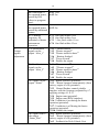
Table 2
X2 pin Signal Name
number
1
2
3
4
5
6
7
8
9
10
RC_out
Heater_Status
Alert_1
Alert_2
Engine_RS
Indication
Sensor_In
Sensor_Out
CAN-L
CAN-H
Polarity Wire colour
+
+
-
Blue-white
Yellow
Grey
Orange
Blue
Red-white
Green-yellow
Green
Brown-white
Brown
Maximum
Electric Load*,
mА
500
500
500
500
500
1000
500
*The connection of outputs 2-5 directly to the Power, without a load, is not
permitted. The connection of outputs 1 and 6 directly to the Ground, without a
load, is not permitted
The signals to be necessarily connected marked in the table by Italics