1
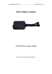
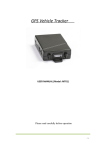
User Manual GPS Vehicle Tracker USER MANUAL (Model: VT900) Please read carefully before operation -1- User Manual Contents 1. Product overview--------------------------------------------------------------------------------------------------3 2. Applications---------------------------------------------------------------------------------------------------------3 3. Product Function and specifications--------------------------------------------------------------------------3 Product Function---------------------------------------------------------------------------------------------------3 Specifications-------------------------------------------------------------------------------------------------------4 4. VT900 and Accessories-------------------------------------------------------------------------------------------5 5. Installation----------------------------------------------------------------------------------------------------------5 Install SIM Card-----------------------------------------------------------------------------------------------------5 Install I/O wire harness-------------------------------------------------------------------------------------------6 5.3 Power/GND ----------------------------------------------------------------------------------------------------------7 5.4 Digital Input (Negative Triggering) -----------------------------------------------------------------------------7 5.5 Digital Input (Positive Triggering) ------------------------------------------------------------------------------7 5.6 Output ----------------------------------------------------------------------------------------------------------------8 5.7 Analog Input (PIN6/AD2) -----------------------------------------------------------------------------------------8 5.8 Install GPS/GSM Antenna ----------------------------------------------------------------------------------------9 5.9 Install Camera (Optional) ----------------------------------------------------------------------------------------9 5.10 Install Microphone and Speaker (optional) ----------------------------------------------------------------9 5.11 Charging ----------------------------------------------------------------------------------------------------------10 5.12 LED Indications --------------------------------------------------------------------------------------------------10 6. Set SMS for GPRS tracking ------------------------------------------------------------------------------------10 6.1 Set ID by SMS ------------------------------------------------------------------------------------------------------10 6.2 Set APN by SMS ---------------------------------------------------------------------------------------------------10 6.3 Set IP Address and Port by SMS -------------------------------------------------------------------------------10 6.4 Enable GPRS Function -------------------------------------------------------------------------------------------11 6.5 Set Time Interval for Sending GPRS Packet ----------------------------------------------------------------11 7. Basic SMS Commands -----------------------------------------------------------------------------------------11 7.1 Position report ----------------------------------------------------------------------------------------------------11 7.2 Set function of receiving actual address name via SMS -------------------------------------------------12 7.3 Get location in Google map URL format --------------------------------------------------------------------12 7.4 To cut off Engine, immobilize the vehicle ------------------------------------------------------------------12 7.5 Set over speed alarm --------------------------------------------------------------------------------------------13 7.6 Harsh acceleration/braking alert -----------------------------------------------------------------------------13 7.7 Oil leaking/Refuel Alarm ---------------------------------------------------------------------------------------13 7.8 Enable Impact Alarm Function---------------------------------------------------------------------------------13 8. Troubleshooting -------------------------------------------------------------------------------------------------14 Appendix 1: Configure by computer ------------------------------------------------------------------------------15 Appendix 2: Presetting by SMS for GPRS tracking -------------------------------------------------------------19 Appendix 3: Configure and use of RFID function --------------------------------------------------------------22 Appendix 4: How to use the camera -----------------------------------------------------------------------------25 Appendix 5: Fuel Sensor Installation and function ------------------------------------------------------------28 -2- User Manual 1. Product overview VT900 is an advanced GPS/GSM/GPRS tracking device which is specially developed and designed for vehicle real-time tracking and security. With superior GPS and GSM modules, VT900 has good sensitivity and stable performance. Especially, VT900 is well designed to work with our web-based tracking system, which is suitable for a company to establish a tracking server to provide real-time tracking solutions to their customer or manage their fleet. It is a fully function tracker that supports camera and voice prompt/broadcasting functions and has strong expansibility and customization ability. 2. Applications Vehicle Real Time Tracking Car security/Anti-Hijack Fleet Management 3. Product Function and Specifications Product Function GPS tracking & RFID car alarm function (need equip RFID kit) Support immediately snapshoot via tracking platform (Need camera support) Two way communication Harsh acceleration Alert/Braking Alert OTA function(support upgrade Over The Air) Oil leaking/Refuel Alarm Get location physical address name by SMS request & from the web-platform Crash alert (optional) Tracking via SMS or GPRS (TCP/UDP) Current location report Tracking by time interval Tracking by distance interval Position logging capacity up to 26,000 + waypoints SOS panic button Geo-fencing control Over speed alert Engine-cut in safety mode Built-in motion sensor for power saving Google map URL for location via SMS, which shows you location on map via mobile phone Remote listen in/Wiretapping Mileage calculation with longitude and latitude via SMS, view mileage data via GPS web-based tracking centre system I/O: 5 digital inputs, 3 negative and 2 positive triggering; 5 outputs. Analog Input: 2 Analog Input for temperature sensor & fuel remote monitoring -3- User Manual Specifications Items Specifications Dimension 105*75*30mm Weight 180g Charging Voltage SIM card type Power consumption 9V~24V 3V Active mode(peak) < 1.0A Active mode(avg.) < 300mA Operating Temperature -20℃~+75℃ Humidity Up to 75% non-condensing External Antenna Connected via 50Ω coax connector External SIM Card Connected via SIM card connector Button 1 SOS and 1 power on/off Microphone Optional Speaker optional Camera Transmit Power optional Class 4(2W) for E-GSM 900 and 850 Class 1(1W) for DCS 1800 Class 1(1W) for PCS 1900 Sensitivity -104dBm minimum for E-GSM 900 AND 850 -102dBm minimum for DCS 1800 GPS Chip -102dBm minimum for PCS 1900 Latest GPS SIRF-Star III chipset GPRS Multi-slot Class 8(4Rx, 1Tx., 5slot Max.) Support all 4 coding schemes(CS-1,CS-2,CS-3 and CS-4) Maximum download speed is 85.6kbps Speech Codec I/O Triple rate Codec Half rate—ETS 06.20 Full rate—ETS 06.10 Enhance full rate—ETS 06.50/06.06/06.08 5 Digital Input ( 2 positive triggering and 3 negative triggering) 2 Analog Input Detection 5 Output -4- User Manual 4. VT900 and Accessories VT900 Main Unit GPS Antenna 16P I/O Wire harness Microphone GSM Antenna Relay Optional Accessories Camera Passive RFID Kits Speaker Active RFID Kits 5. Installation Install SIM Card Check that the SIM has not run out of credit (test the SIM in a phone to make sure it can send and receive SMS); Before installing the SIM card, turn off the power for VT900. Then install the SIM card as following: -5- Fuel Sensor Temperature Sensor User Manual Install I/O wire harness The I/O wire harness is a 16-pin wire harness including power wire, Analog input wire, negative/positive input and output wire PIN Number Color Description IN1/SOS White Digital Input 1 (negative triggering) IN2 White Digital Input 2 (negative triggering), e.g. detecting status of vehicle door. IN3 White Digital Input 3 (negative triggering) IN4 White Digital Input 4 (positive triggering), e.g. detecting the ACC. IN5 White Digital Input 5 (positive triggering). AD1 Blue 10 Bits Resolution Analog Inputs. 0~6V DC Detection. It can be used to connect with temperature/fuel sensor etc. GND Black Ground POWER Red DC In (power source). Input voltage: 9V~36V. 12V suggested. OUT1 Yellow Output1. It can be used to connect with relay for engine immobilization. Low voltage (0V) when effective and open drain (OD) when ineffective. Output open drain sink voltage (ineffective): 45V max. Output low voltage sink current (effective): 500mA max. OUT2 Yellow NC OUT3 Yellow E.g. connected with siren OUT4 Yellow E.g. unlocked car door OUT5 Yellow E.g. Lock car door AD2 Blue 10 Bits Resolution Analog Inputs. 0~6V DC Detection. It can be used to connect with temperature/fuel sensor etc. GND Black Ground. POWER Red DC In (power source). Input voltage: 9V~36V. 12V suggested. Same as PIN8 -6- User Manual 5.3 Power/GND Connect GND (-Black) and Power (+Red) wires to the battery of vehicle. 5.4 Digital Input (Negative Triggering) E.g. Detecting SOS button Input 1 or Input 2 or Input 3 White SOS Button E.g. detecting vehicle door open/close Power for Relay Relay for lock control Power for lock Motor White lock unlock Lock switch 5.5 Digital Input (Positive Triggering) E.g. detecting engine on/off status -7- Input 1 or Input 2 or Input 3 User Manual 5.6 Output E.g. Control fuel-cut 5.7 Analog Input (PIN6/AD2) 5.7.1 Analog Input Application 1– Detect External Power Voltage Input range:0-6V Voltage Calculating Formula: input voltage=(AD*6)/1024 0x0377=>887(Decimal)=>(887*6)/1024=5.1972V(Voltage) OxO2FB=>763(Decimal)=>(763*6)/1024=4.4707(Voltage) Note: Fuel level sensors supplied by our company are resistance-type sensors with output resistance: 0-200Ù (Ohm). For the circuit shown on above figure, if VCC is 12V, R should be 200Ù (ohm) and if VCC is 24V then R should be 600Ù (ohm) to make the input range to AD1 or AD2 is 0-6V. Below formula is for calculating the fuel percentage left for this fuel level sensor: AD value Percentage Left = * 100% 1024* 2 – AD value The value must be converted into decimal, for example, 0x0267 is 615 in decimal. -8- User Manual 5.8 Install GPS/GSM Antenna Connect the GSM antenna to the SMA connector which is ‘GSM’ text labeled. The GSM antenna is non-directional, so you can hide it in any place of vehicle. Connect GPS antenna to the GPS connector which is ‘GPS’ labeled. The optimum location for the GPS antenna is on the roof of the vehicle. The covert and GPS antenna are directional, make sure they are facing up and lying as flat as possible. Secure them in place with glue or zip ties. Note: Do not shield or cover the GPS antenna with any objects containing metal. 5.9 Install Camera (Optional) (more Specific details refer to Appendix 3) 5.10 Install Microphone and Speaker (optional) -9- User Manual 5.11 Charging Connect the device with external power like car battery, and turn on its power switch and it will do charging automatically. 5.12 LED Indications Insert the 16-Pin wire harness and push the power switch to turn on/off VT900 GPS LED (Red) Flashing ( every 0.1 second) Initializing or back-up battery power is low Flashing (0.1 second on and 2.9 seconds off) VT900 has a GPS fix Flashing (1 second on and 2 seconds off) VT900 has no GPS fix GSM LED (Green) Flashing ( every 0.1 second) Initializing Flashing (0.1 second on and 2.9 seconds off) VT900 is connected to the GSM network Flashing (1 second on and 2 seconds off) VT900 is not connected to the GSM network 6. Set SMS for GPRS tracking 6.1 Set ID by SMS Command: W<password>,010,ID Description: every tracker has a unique ID. Tracker ID must be less than 14 digitals Example: SMS send:W000000,010,20120823 Meaning: this tracker’s ID is 20120823 6.2 Set APN by SMS Description: W<password>,011, APN name, APN username, APN password if no username and password required, just put in APN name only. Command: W<password>,011,APN name,APN username, APN password 6.3 Set IP Address and Port by SMS Command :W<password>,012,IP,Port Description: Our online tracking website’s IP address is 210.209.68.180 Port is 9500 Example: SMS send: W000000,012,210,209,68,180,9500 We support domain name instead of IP address: Example: W000000,012,www.global-track.net,9500 - 10 - User Manual 6.4 Enable GPRS Function Command: W<password>,013,X Description: X=0, close GPRS (Default) X=1, enable TCP X=2, enable UDP 6.5 Set Time Interval for Sending GPRS Packet Command :W<password>,014,XXXXX Description: XXXXX should be in five digitals and in unit of 10 seconds. XXXXX =00000, to disable this function XXXXX =00001~65535, time interval for sending GPRS packet and in unit of 10 seconds 7. Basic SMS Commands 7.1 Position report Description: To know the position of your VT900, send an SMS or make a telephone call directly to VT900 and you will receive an SMS with its location and other information. Command: W<password>, 000 Note: The default password is 000000 (the following the same) Item ID: 1234567890 ACC=OFF Latitude=23 08 57.58N, longitude=113 18 59.31E Speed=0.00Km/h Odometer=0.013km/h 2012-09-26,11:32 Description The tracker’s ID number The engine is turned off Latitude and longitude information, “N” in latitude means North ,”E” in latitude means East, Speed information Odometer information Date and time You can copy this coordinate get from the SMS into http//:maps.google.com and see its location as below: Another easier way to get VT900’s position: Use your mobile phone to call the SIM number in the VT900, after hearing several times ring, then hung up, VT900 will send a SMS with location information back to your mobile phone. - 11 - User Manual 7.2 Set function of receiving actual address name via SMS Description: To know specific address of your VT900, send an SMS and you will receive an SMS with its location physical address name. (This command needs our GPRS tracking platform GPRS-01 support) Command: W<password>,111 Example: SMS send: W000000, 111 SMS receive: Xinfu 1st Rd, Maonan, Maoming, Guangdong, China 7.3 Get location in Google map URL format Description: You will get a Google map URL after sending the command, click the URL then the location can be shown directly on Google Maps on your mobile phone. Command: W<password>,100 Example: SMS send: W000000,100 SMS Received: as following picture 1 Note: then by click the URL, you can get the location in Google map from your mobilephone, see bellowing picture 2 1 2 7.4 To cut off Engine, immobilize the vehicle Command: W<password>,020,P,F Description: P=1, means output1, P=2 means output2 … P=5, means output5 F=0, to disable this output function; F=1, to enable this output function Example: SMS send: W000000,020,1,1 If the output1 is connect to oil-cut relay, this command is to enable the engine-cut function, the engine oil pump line will be cut-off to immobilize the vehicle. While send W000000,020,1,0 is to restore the engine oil pump line and the vehicle can be started again. - 12 - User Manual 7.5 Set over speed alarm Command :W<password>,005,XX Description: XX(the speed preset value) XX=00, disable XX=[01<XX<20](unit:10Km) Example: SMS send:W000000,005,10 SMS receive: SET OK! SPEED LIMIT:100Km/h Meaning: If your speed is over 100Km/h, an alarm SMS will send to your phone to warn you. 7.6 Harsh acceleration/braking alert SMS command: W<password>,047,X Description: X means value of velocity change, 1 to 2 digitals. Default value is 0 for disable acceleration/braking alert function. (1) Acceleration Alert: When the speed is over 20km/h, if the speed increase over X km/h in 5 seconds, the tracker will trigger acceleration alert, send the alarm data to tracking platform, its alarm code is 0x73. Example: SMS send: W000000,047,5 Meaning:When the speed is over 20km/h, if the speed increase over 5 km/h in 5 seconds, the tracker will trigger acceleration alert, send the alarm data to tracking platform. (2) Braking Alert: When the speed is over 20km/h, if the speed decrease over (X+10) km/h in 5 seconds, the tracker will let out braking alert, send the alarm data to tracking platform, the protocol number is 0x72. Example: SMS send: W000000,047,10 Meaning: When the speed is over 20km/h, if the speed decrease over 20 km/h in 5 seconds, the tracker will let out braking alert, send the alarm data to tracking platform. 7.7 Oil leaking/Refuel Alarm SMS command: W000000,094,X Description: X = 000~199(unit: second), means for fuel capacity change exceed preset value in the time interval X, it will send out oil leaking or fueling alarm, send alarm data to tracking platform, the leaking protocol number is 0x74, the fueling protocol number is 0x76. And if X is less than or equal to 5 seconds, then the function will be disabled. System default value is 10 seconds. 7.8 Enable Impact Alarm Function: SMS command: W<password>,028.1 Meaning: If the vehicle impact , an alarm SMS will send to your phone to warn you Disable Impact alarm function: SMS command: w<password>,028,0 When sending out impact alarm, alarm data will be sent to platform, alarm code is 0x14 System’s default setting is disable function of impact alarm More commands please refer to appendix 2 - 13 - User Manual 8. Troubleshooting Problem: Unit will not turn on Possible Cause Resolution Wiring was not connected properly Check and make sure wiring connection is on order Battery needs charging Recharge battery Problem: Unit will not respond to SMS Possible Cause Resolution Make VT900 connected to GSM GSM antenna was not installed properly Network. GSM Network is slow Wait for SMS. Some GSM networks slow down during peak times or when they have equipment problems. Wrong password in your SMS Insert the correct password The SIM in VT900 has run out of credit Replace or top up the SIM card No SIM card Insert working SIM card. Check in phone that the SIM can send SMS messages. SIM card has expired Check in phone that the SIM can send SMS messages. Replace SIM card if needed. - 14 - User Manual SIM has PIN code set Remove PIN code by inserting SIM in you phone and deleting the code SIM is warped or damaged Inspect SIM, clean the contacts. If re-inserting does not help try another to see if it will work. Roaming not enabled If you are in a different country your SIM account must have roaming enabled Battery is low Recharge the unit and the GSM will start working. Problem: SMS from VT900 states “last......” Possible Cause Unit does not have clear view of the sky Resolution Move the antenna of the unit to a location where the sky is visible. VT900 is in an inner place Wait for the target to come out Appendix 1 Configure by computer This part shows the basics of how to use the TOPSHINE Parameter Editor. Note: Don’t connect VT900 to external battery when configuring. How to Edit the Parameters of VT900 Step 1 Buy one specific USB cable for configuration from Our Company - 15 - User Manual Step 2 . 1. Install USB driver program for the configuration USB cable Run ‘CP210x_Prolific_DriverInstaller’ to install the driver for the USB data cable. Note: CP210x_Prolific_DriverInstaller is in the folder ‘USB-232 Driver’ in the CD. Connect the USB Data Cable between VT900 and PC. 2. Connect the configuration cable with PC, open device management of your computer. You can find “Prolific USB-to-Serial Comm. Port ” , as following picture shows. The USB port is virtual comm. Port (com3) in this example, Step3 .Open the GPS Tracker Parameter Editor 1. Connect VT900 with PC by the configuration cable 2. Confirm VT900 is in the Power Off states 3. Double click GPS Tracker Parameter Editor.exe and Select the COM Port, following picture shows: - 16 - User Manual 4. Click Start button to open the com port. 5. Turn on VT900and it will connect with the Editor automatic, As soon as they connect successful, all the buttons are availability and the status bar will clue on’ Tracker Connect!’ , then you can Read or Write the VT900’s Parameters . - 17 - User Manual Instruction of parameter setting: Item Description GPRS Tick to enable GPRS function, select TCP or UDP mode Tracker ID APN, APN Password Account, APN Should be unique, in number, maximum 14 bytes Put your local APN, APN username and password if necessary IP, Port Put online tracking server IP and port, our default is IP: www.global-track.net port: 9500 Interval To put time interval to upload a data Item SMS tracking No. Interval Password Over Speed Prefix(area code) Time Zone Wiretapping Distance Power Saving Course Item SMS Call SOS Button/IN1 Description To put a mobilephone number for automatic tracking by SMS at certain time interval in minutes To set SMS command password, the default is 000000, To set speed limit for overspeed alarm To set country code To set time zone, GMT*60 (minutes), if in west half western hemisphere, “-” is necessary to put ahead To set wiretapping mobilephone number To set track and upload data by certain distance in meters To set time enter into standby mode when shaking not detected to save power and gprs data traffic To set upload data via angle shifting by certain angles Description To set Mobilephone No. for SMS or Calling when SOS button/Input 1 is triggered - 18 - User Manual SMS Call Button B/IN2 SMS Call Button C/IN3 SOS Button/IN1 Button B/IN2 Button C/IN3 To set Mobilephone No. for SMS or Calling when Button B/Input 2 is triggered To set Mobilephone No. for SMS or Calling when Button C/Input 3 is triggered To customize the reply SMS text when SOS Button/Input 1 triggered To customize the reply SMS text when Button B/Input 2 triggered To customize the reply SMS text when Button C/Input 3 triggered Call for SMS Cut off Power Tick it to reply SMS when calling in Tick it to send alert when the external power be cut off Appendix 2 Presetting by SMS for GPRS tracking Set ID for VT900 by SMS W******,010,ID Tracker ID must be less than 14 digits Set APN by SMS W******,011,APN,APN APN Name, APN Password If no Name, APN Password password required, just insert APN name only; APN defaulted as ‘CMNET’; APN name + password not over 39 characters. Set IP Address and Port by W******,012,IP, Port SMS Enable GPRS Function IP: xxx.xxx.xxx.xxx Port: [1,65536] W******,013,X X=0, close GPRS (default); X=1, enable TCP X=2, enable UDP Set Time Interval for W******,014,XXXXX Sending GPRS Packet XXXXX should be in five digitals and in unit of 10 seconds. XXXXX=00000,to disable this function; XXXXX=00001~65535, time interval for sending GPRS packet and in unit of 10 seconds. Output Control W******,020,P,F P =1, Out1 =2, Out2 =3, Out3 - 19 - User Manual =4, Out4 =5, Out5 F =0, to disable the output =1, to enable the output Output Control (Safe W******,120,ABCDE ABCDE represents Out1, Out2, Out3, mode) Out4, Out5 respectively. This function is achievable If A or B or C or D or E, when the speed is below =0, to disable the output 10km/h and GPS is =1, to enable the output available. =2, to remain previous status Set power saving mode W******,026,XX XX=00, to disable this function when VT900 is still XX=01~99, to set this function. It is in (In power saving mode, GPS stops unit of minute. working. GSM enters standby mode Example: and stop sending out message until If XX=10, VT900 will enter power it is activated by an SMS or an saving mode in 10 minutes after it is incoming call) immobile. Set phone number for W******,030,T wiretapping T is the telephone number for wiretapping and max. 16 digits Set time zone difference W******,032,T T=0, to disable this function T=[1, 65535] to set time difference in minutes to GMT. Default value is GMT +, not necessary for those ahead of GMT. For example, either +120 or 120 is acceptable. -, required for those behind GMT. For example, -120. Set character for SOS alert W******,033,P,Char message Char P is the button number. P=1, 2, or 3. Char is the character in SOS message and max 32 characters Set tracking by driving angle W******,036,Degree change function Measured by Degree(s), Degree=0,disable this function ; X=1-359 , means set angle degree interval in this function. Set tracking by distance function W******,045,X Measured by Meter(s), X=0, disable this functio;X=1—65535, means the distance interval in this function. Set clear/reset odometer function W******,046 To clear and reset odometer information to zero. - 20 - User Manual Set function of receiving location W******,111 This function need support of the physical address name via SMS GPRS01 or SMS01 tracking platform, address SMS will be received in text format. Get version and serial W******,600 To get version and serial number of number current firmware Get IMEI No. W******,601 To get device IMEI No. Reboot GPS and GSM Module W******,900### ### is the ending character. Initialization W******,990,099### ### is the ending character. W888888,999,666 This command will reset the current To turn all the parameters / settings (except for the password) to factory default. Password Initialization password to factory default password 000000 Description Command Remarks Get current location W******,000 Get current location of VT900 Get location in Google W******,100 http://maps.google.com/map s?f=q&hl=en&q=22.542563 map URL format via SMS ,114.077971&ie=UTF8&z= 16&iwloc=addr&om=1 Change user’s password W******,001,###### ****** is old password ###### is new password Set interval for W******,002,XXX automatic timed reports Set preset phone XXX is the interval in minute. If XXX=000 it will stop tracking W******,003,F,P,T F=0, to disable this function; number F=1, only sending SMS; for SOS button F=2, only calling preset phone number; F=3, both SMS and calling (default) P is the button number and should be 1,or 2, or 3. If SOS button is linked to IN1, then P=1. T: Preset phone number (T must be less than 16 digits) Set over speed alarm When VT900 speeds higher W******,005,XX XX (the speed preset value) =00 , disable =[01<XX<20] (unit: 10Km) than the preset value, it will send one over speed alarm SMS to the SOS preset - 21 - User Manual number. Set Geo-fence alarm W******,006,XX XX (set distance from current central point place ) (foursquare) =00, disable When the VT900 moves =01, 30m out =02, 50m of preset scope, it will =03, 100m send =04, 200m one Geo-fence SMS to =05, 300m the =06, 500m SOS preset number. =07, 1000m =08, 2000m Extend Settings W******,008,ABCDEF A=0, disable position report function GHIJ### when a call is made to VT900 A=1, enable position report function to get position SMS by Calling VT900 I=0, disable power failure alert I=1, enable power failure alert The functions of BCDEFGHJ are remained for furthur use. ### is the ending character. Set Geo-fence alarm 017 command is alarm tracker when W******,017,data data is the coordinates which include: W******,117,data Lower-left X, Lower-left Y,Upper-right X,Upper-right Y for For example, 11404.0000,E,2232.0010,N,11505.1234,E,2333.5678,N moves out the preset Note: scope; 1. Lower-left X,Y (longitude and latitude) should be 117 command is alarm tracker when for smaller than Upper-right X,Y; 2. All longitudes and latitudes should be in ASCII format moves in. as follows:- When the tracker moves Longitude: DDDMM.MMMM,E/W. 4 places of decimal. ‘0’ in or out, it will send an is needed to be stuffed if no value available. SMS Latitude: DDMM.MMMM,N/S. 4 places of decimal. ‘0’ is alarm authorized to the phone number for SOS. needed to be stuffed if no value available; 3. Send W******,017 or W******,117 without data to disable this function. Appendix 3: Configure and use of RFID function RFID Reader RFID Tag - 22 - User Manual 1. Install RFID as following: 2. How to use 2.1 SMS Commands 2.1.1 Firstly, enable the RFID: (1) Enable the RFID function:W000000,062,1 (2) Disable the RFID function: W000000,062,0 (3) The system default is RFID function enabled. (4) When send the disarming SMS command ”000000DSM”, it will automatic disable the RFID function, and if send the enable SMS command the RFID function will be restored. 2.1.2 Secondly To configure authorized RFID tag by SMS commands W<password>,060,num1 W<password>,160,num2 W<password>,260,num3 W<password>,360,num4 W<password>,460,num5 Note: The default password is 000000 Num1, num2, num3, num4, num5 means 5 digital FRID number. For example: if configure NO.00412 as the authorized RFID tag, then send SMS: W000000,060,00412 Tracker will reply SMS “STUDY ID OK: 1:00412; 2:00000; 3:00000; 4:00000; 5:00000”, means the 1st RFID tag number is 00412, the 2nd , 3rd, 4th, 5th RFID tag not set. If the RFID tag is detected at this time, tracker will send SMS “NOW ID : 00412 “ . Another way to configure authorized RFID tag by Parameter. Step 1: Open GPS Tracker Editor (2010) V2.65 (following picture) (Following Appendix 1 to configure the tracker) - 23 - User Manual Turn on MT100 and it will connect with the Editor automatic, As soon as they connect successful, all the buttons are availability and the status bar will clue on’ Tracker Connect!’ , then you can Read or Write the MT100’s Parameters Step 2: Finding RFID Settings (as following picture). Following the digital sort to do: 1. write the RFID tag’s number, (example: 00412) 2. click Apply, then display “com operate success” ,click the OK; 3. Click the Read. 4. Then it will display “412” it prove already configure authorized RFID tag succeed. If you want to configure multiple RFID tags, just like the example “00412,00234,00322,*****”; after write success, it will display” 412,234,322,***” Note: RFID reader detecting test RFID tag distance is within 5 meters, the RFID tag must be detected before RFID can be used. 2.1.3 The ARMING SMS command: “<password>ARM ” The disarming SMS command “<password>DSM ”, When send the disarming SMS command “000000DSM”, it will automatic disable the RFID function, and if send the enable SMS command the RFID function will be restored. 2.1.4 Judge if need to cut off oil/fuel supply when the ignition alert occurs to stop engine start. Enable function of cutting off oil-way when illegally ignite under ARM status SMS command: W<password>,061,1 Disable function of cutting off oil-way when illegally ignite under ARM status SMS command: W<password>,061,0 The system default setting is disable function of cutting off oil-way when illegally igniting under ARM status. - 24 - User Manual 3. Command List Description Configure authorized RFID tag Command Reply SMS W<password>,060,num1 STUDY ID OK: 1:num1; 2:num2; W<password>,160,num2 3:num3; 4:num4; 5:num5 W<password>,260,num3 W<password>,360,num4 W<password>,460,num5 Enable the RFID detection W<password>,062,1 ENABLE OK ! Disable the RFID detection W<password>,062,0 DISABLE OK ! Arm <password>ARM Vehicle is armed! Disarm <password>DSM Enable function of cutting off W<password>,061,1 System default setting is disable oil-way when illegally ignite under function of cutting off oil-way when ARM status illegally ignite under ARM status. Disable function of cutting off W<password>,061,0 oil-way when illegally ignite under ARM status 4. Functions 4.1 To ignite in Armed status, it will check the RFID tag. If an authorized tag can be detected, it will not alert. If an authorized tag can not be detected, it will send alert SMS “Engine Is On !” to three authorized alert mobilephone numbers, and at the same time, the Output 3 will control siren to sound, and call the three mobilephones at one minute interval, and decide to cut off the oil/fuel supply according to its oil cut enable/disable status. 4.2 If vehicle door is opened in armed status, it will check the RFID tag. If an authorized tag can be detected, it will not alert; if an authorized tag can not be detected, it will send alert SMS “Door Is Open !” to three authorized alert mobilephone numbers, and the Output 3 will control the siren to sound, and call the three mobilephone numbers at one minute interval. 4.3 If the vehicle is moved/towed in armed status, it will detect the RFID tag, if no authorized tag be detected, st it will send alert SMS ”Movement alarm!” to the 1 alert mobilephone number. 4.4 In disarmed status, if no authorized RFID tag Is detected for successive 30 seconds, then the system will st automatically arm the vehicle, and it will call the 1 alert mobilephone number, after several rings and hang off automatically, indicating the vehicle be armed. 4.5 If alert be triggered, the siren will sound for 10 seconds and shut or immediately shut when disarm action is detected. 4.6 If illegal ignition be detected and oil/fuel supply cut off enabled, then the oil/fuel supply will be cut off, and it will be immediately restored as soon as disarm action be detected. 4.7 If the oil/fuel supply is cut off by SMS or GPRS platform, it can not be restored by disarm action. - 25 - User Manual 5. RFID on the platform applications 5.1 Into our GPS Tracking Platform: http;//www.global-track.net, as following picture P1,login interface, as following picture P2 P1 P2 5.2 Select your device, such as instructed 1;it will display your car’s the current information, Driver (ID) means the driver and his/her RFID tag number such as instructed 2; 5.3 If you want to edit the driver information, please click “manage” ,such as instructed 3, then interface will into as following picture P3; P3 5.4 Click Driver Manage , such as instructed 4;it will open such as instructed A; You can click New, such as instructed 5, open as following picture P4; to add tag ID and the driver’s information etc. - 26 - User Manual P4 Appendix 4: How To Use The Camera 1. Install camera 2. How to take photos: 2.1 Send SMS commands to set take photos : Description Command Remarks A : Snap or not when IN1 alert triggered, A=1 means snap, A=0 means no action B : Snap or not when IN2 alert triggered, B=1 means snap,B=0 means no action C: Snap or not when IN3 alert triggered, C=1 means snap, C=0 means no action D: Snap or not when IN4 alert triggered, D=1 means snap,D=0 means no action E: Configure SMS for the Snap or not when IN5 alert triggered, E=1 means snap, E=0 means no action W<password>,108,<ABCDEFGHIJ…> F: Snap or not when over speed alarm triggered, extended F=1 means snap, F=0 means no action photoing G: Snap or not when movement alarm triggered, parameters G=1 means snap, G=0 means no actions H: Snap or not when Geo-fencing alarm triggered, H=1 means snap, H=0 means no actions I: Snap or not when power fail alert triggered, I=1 means snap, I=0 means no actions J: Snap or not when Oil/fuel leakage alarm triggered, J=1 means snap, J=0 means no actions The system all default is 0 , no actions. By send SMS W<password>,051 to Roll call take photos: - 27 - User Manual Camera Failure Alarm, send SMS "CAMERA ERROR ALARM!" to SOS number, and send alarm data to platform as well, alarm code 0x75 2.2 Configure tracker to set take photos Open gps tracker parameter editor (2010)v2.65(following picture) Finding photo enable in the Extend Settings(as following picture) In photo enable option, Choose you want to select the function. Such as select IN1 alarm , means when trigger IN1 alarm ,tracker will automatic take photo. 2.3 On the platform applications Into our GPS Tracking Platform: http;//www.global-track.net , (following picture P1),login interface,(following picture P2) - 28 - User Manual P1 P2 Select your device, such as instructed 1; it will display your car’s the logo on the map(instructed). Put the mouse on the logo, It will automatically pop up frame (instructed 3),you can click the ”Take Photo” in the options (instructed 3),then it will taking photo down (following picture P3).If you want to see photos record, please click “Report Centre”(instructed 4),then The Report interface will pop up;(following picture P4) P3 P4 In Reports options, there is a Picture Report, click it (instructed5), then it will display “Picture Report” interface. Choose you want to choose the vehicle (instructed6), wait for few seconds, it will display the Picture Report, click “view”, Will see you want to see pictures(instructed 7) Appendix 5: Fuel Sensor Installation and function 1. Installation instruction 1.1 Installation flow chart: - 29 - User Manual 1.2 Operation procedures: 1.2.1 Find the position Generally installed in the middle of the fuel tank, to avoid the original fuel floater 1.2.2 Clean the oil stain on the installation position Clean the oil stain on the installation position 1.2.3 Holing Use hand-drill with a 42mm metal drill bit, connect the power supply and drill in the position (Note: please do not drill too fast, stop when it is about to drop, then use the screwdriver and sharp-nose plier to remove the attached metal scraps to prevent them dropping into the tank ). Special note: Make sure to open the fuel tank cap before drilling; it’s better to drain away all diesel, if not, just make sure not too full in the tank. 1.2.4 Cleaning work Use the grater to polish the rough selvedge; Use a rope-tied magnet to adsorb the iron scraps. 1.3 Flange installation 1.3.1 Put the gasket under the flange and holing, then tighten with screws. 1.3.2 Put sealing ring 1.3.3 The sensor has two circle sealing rings, first fit the bigger ring and then the small one, fix them on the top of the sensor, see the flow chart. 1.3.4 Screw tighten the sensor 1.3.5 Put the sensor into the flange opening, and screw tighten along the screw thread direction, then wiring and wrapping. 1.3.6 Power supply of the fuel sensor The sensor power voltage is 18-32VDC. Note: Do not connect the biggest power line in the vehicle, please connect the normal size power line, otherwise will burn the sensor. 1.4 Tools required Tools: Hand-drill, Metal hole saw, Hex tapping screws (3cm) Pistal Drill Hole saw Hexagon self tapping screw Extension cable of Fuel sensor: it’s better wiring along the fuel tank, generally for a big vehicle, 9~10 m cable is enough and 5~8 m for a small vehicle; choose the 3-core, 0.75mm2 cable. 2 Fuel sensor on the platform applications 2.1 Into our GPS Tracking Platform: http;//www.global-track.net , as following picture P1,login interface,(as following picture P2) - 30 - User Manual P1 P2 P2 2.2 Select your device, such as instructed 1; it will display your car’s the current oil/Fuel (L) (instructed2). 2.3 If you want to see the history record chart. Please click “Report Centre”(instructed 3), then the Report interface will pop up; (following picture P3) P3 2.4 In Report options, there is a Fuel Report (Line), click it (instructed 4), then it will display instructed 5, 6; you need choose “vehicle, Time or data etc.”, and click search (instructed 6), later it will display “Fuel Line” chart. - 31 -