1
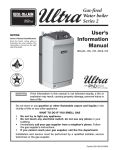
Universal Fire Tube Boiler Wall Mount Models USER’S INFORMATION MANUAL Models UFT-80W / 100W / 120W / 140W / 175W / 199W Heat Exchanger Bears the ASME “H” Stamp NOTICE: HTP reserves the right to make product changes or updates without notice and will not be held liable for typographical errors in literature. NOTE TO CONSUMER: PLEASE KEEP ALL INSTRUCTIONS FOR FUTURE REFERENCE. IF THE INFORMATION IN THIS MANUAL IS NOT FOLLOWED EXACTLY, A FIRE OR EXPLOSION MAY RESULT, CAUSING PROPERTY DAMAGE, PERSONAL INJURY, OR LOSS OF LIFE. DO NOT STORE GASOLINE OR OTHER FLAMMABLE VAPORS AND LIQUIDS IN THE VICINITY OF THIS OR ANY OTHER BOILER. WHAT TO DO IF YOU SMELL GAS Do not try to light any boiler. Do not touch any electrical switch. Do not use any phone in your building. Immediately call your gas supplier from a neighbor’s phone. Follow the gas supplier’s instructions. If you cannot reach your gas supplier, call the fire department. Installation and service must be provided by a qualified installer, service agency, or the gas supplier. 120 Braley Rd. P.O. Box 429 East Freetown, MA 02717-0429 www.htproducts.com LP-543 REV. 12.15.15 2 The following defined terms are used throughout this manual to bring attention to the presence of hazards of various risk levels, or to important product information. DANGER indicates an imminently hazardous situation which, if not avoided, will result in death or serious injury. WARNING indicates a potentially hazardous situation which, if not avoided, could result in death or serious injury. CAUTION indicates a potentially hazardous situation which, if not avoided, may result in minor or moderate injury. CAUTION used without the safety alert symbol indicates a potentially hazardous situation which, if not avoided, may result in property damage. NOTICE NOTICE is used to address practices not related to personal injury. SAFETY INSTRUCTIONS SAFETY INSTRUCTIONS (or equivalent) signs indicate specific safety related instructions or procedures. NOTE: Contains additional information important to a procedure. LP-543 Rev. 12.15.15 3 TABLE OF CONTENTS PART 1 – PRODUCT AND SAFETY INFORMATION ............................................................................................................................... 4 A. BEFORE OPERATION ...................................................................................................................................................................... 4 B. DURING OPERATION ....................................................................................................................................................................... 5 C. TROUBLESHOOTING AND GENERAL CAUTIONARY STATEMENTS ........................................................................................... 5 PART 2 – MAINTENANCE ........................................................................................................................................................................ 6 A. SERVICE TECHNICIAN .................................................................................................................................................................... 6 B. OWNER MAINTENANCE .................................................................................................................................................................. 7 PART 3 – MAINTENANCE PROCEDURES .............................................................................................................................................. 7 A. DAILY MAINTENANCE – TO BE PERFORMED BY OWNER ........................................................................................................... 7 B. MONTHLY MAINTENANCE – TO BE PERFORMED BY OWNER.................................................................................................... 8 C. 6 MONTH MAINTENANCE – TO BE PERFORMED BY OWNER ..................................................................................................... 8 D. ANNUAL MAINTENANCE – ONLY TO BE PERFORMED BY A QUALIFIED SERVICE TECHNICIAN............................................ 9 PART 4 – TROUBLESHOOTING .............................................................................................................................................................. 9 MAINTENANCE NOTES .................................................................................................................................................................. 10 LP-543 Rev. 12.15.15 4 PART 1 – PRODUCT AND SAFETY INFORMATION USER – Have this boiler serviced/inspected by a qualified service technician annually. TO TURN OFF GAS TO THE BOILER 1. Set the thermostat to the lowest setting. 2. Turn off all electrical power to the boiler. 3. Turn manual gas shutoff valve to “OFF”. Proper care of this boiler is the user’s / owner’s responsibility. The user / owner should carefully read and understand the Operating Information in this manual before operating this boiler. It is the user / owner’s responsibility to know the location of the gas shut-off valve and how to operate it. Immediately close the gas shut-off valve if the boiler is subjected to fire, overheating, flood, physical damage, or any other damaging condition that might affect the operation of the unit. Have the boiler checked by a qualified technician before resuming operation. DO NOT use this boiler if ANY part has been under water. Immediately call a qualified technician to inspect the boiler and replace any part of the control system or gas control which has been under water. DO NOT power up the boiler unless the gas and water supply valves are fully opened. Make sure the fresh air intake pipe and exhaust vents are open and functional. DO NOT attempt to install, repair, or service this boiler. Contact a qualified technician if the boiler needs repair or maintenance. Ask your gas supplier for a list of qualified service providers. DO NOT use spray paint, hair spray, or any other flammable sprays near the boiler or near the exterior fresh air intake pipe termination. DO NOT place any items in or around the exterior exhaust vent termination and/or fresh air intake pipe that could restrict or block the flow in or out of the vent system. All safety devices must be tested by the installer / service technician after the boiler is installed. Always verify proper boiler operation with the service technician after servicing. The gas ignition system components must be protected from water (dripping, spraying, rain, etc.) during boiler operation and service (circulator replacement, condensate trap, control replacement, etc.) The Er:80 code will display when there is no water in the boiler. Ensure the boiler is full of water and all air has been purged from the system. Then manually reset the boiler to resume operation. If the Er:80 code displays again, call a qualified service technician to inspect the boiler. This boiler features a factory installed overheating prevention device. This limit provides boiler shutdown in the event that the boiler water temperature exceeds the set point of the limit control. Certain local codes require additional water temperature limiting devices. FAILURE TO ADHERE TO THE GUIDELINES IN THIS MANUAL CAN RESULT IN SUBSTANTIAL PROPERTY DAMAGE, SEVERE PERSONAL INJURY, OR DEATH. A. BEFORE OPERATION 1. Check the Gas Type (NG/LP) When operating the boiler for the first time, ensure the connected gas type matches that of the gas type of the boiler. Check whether the gas supplied is NG or LP. The boiler gas type is indicated on the rating plate on the side of the boiler. Attempting to operate this boiler on a gas supply other than specified on the rating plate will result in improper boiler operation, and could result in property damage or personal injury. 2. Check the Power (120V 60Hz) Ensure the boiler is connected to a properly rated power supply. 3. Check the Automatic Feed Valve Ensure the automatic feed valve to the boiler is providing the proper pressure to the central heating (CH) loop. 4. Check the Gas Shut-Off Valve Ensure the manual gas shut-off valve is open. The boiler will not operate unless it is supplied with gas. 5. Check the Area around the Boiler Remove any combustible or flammable materials from the area around the boiler and do not hang anything from the exhaust vent pipe. Do not operate the boiler if its combustion air intake is located in or near one of the areas or in the vicinity of products listed in Table 1. These areas will always contain hazardous contaminates that can form strong acids while passing through the burner and vent system. These acids will corrode the boiler’s heat exchanger, burner components and vent system, resulting in flue gas spillage and/or water leakage, possible substantial property damage, severe personal injury, or death. If the boiler combustion air intake is located in any area likely to cause or contain contamination, or if products which would contaminate the air cannot be removed, the intake must be repiped and terminated to another location. DO NOT re-pipe the combustion ventilation system on your own. Call a qualified service provider for assistance. LP-543 Rev. 12.15.15 5 PRODUCTS TO AVOID Spray cans containing fluorocarbons Permanent wave solutions Chlorinated waxes/cleaners Chlorine-based swimming pool chemicals Calcium chloride used for thawing Sodium chloride used for water softening Refrigerant leaks Paint or varnish removers Hydrochloric or Muriatic acid Cements and glues Antistatic fabric softeners used in clothes dryers Chlorine-type bleaches, laundry detergents, and cleaning solvents Adhesives used to fasten building products Table 1 AREAS LIKELY TO HAVE CONTAMINANTS Dry cleaning/laundry areas and establishments Swimming pools Metal fabrication plants Beauty shops Refrigeration repair shops Photo processing plants Auto body shops Plastic manufacturing plants Furniture refinishing areas and establishments New building construction Remodeling areas Garages and workshops B. DURING OPERATION 1. Check for Gas Leaks Frequently check the gas pipe and connections for leaks with a soapy solution. If air bubbles appear during the test, gas is leaking. Close the gas supply valve and call your gas supplier for inspection. After any repair of the gas pipeline or replacement of the gas regulator, call a qualified service technician to observe the installation and replacement before restoring power to the boiler. Failure to do so could result in a fire or explosion, substantial property damage, severe personal injury, or death. 2. Check Exhaust Vent and Intake Pipe for Proper Ventilation Ensure there is sufficient ventilation while operating the boiler. Improper ventilation could result in premature boiler failure. Such failures ARE NOT covered by boiler warranty. Exhaust gas entering the living space can cause carbon monoxide poisoning. If exhaust gas should leak into the living space: Shut down the boiler. Close the gas valve. Open windows for ventilation. Ensure that the CO detectors are operating properly. Immediately call a qualified service technician to inspect the boiler and exhaust vent pipe. Any damages to the exhaust vent pipe should be repaired immediately. Failure to do so could result in substantial property damage, severe personal injury, or death. 3. 4. Burn Warning Take caution when inspecting the boiler and its internal components, exhaust vent, and/or water pipes. These components can get extremely hot during boiler operation. Combustibles and Flammable Material Warning Do not store combustibles or flammable materials in the vicinity of this boiler. Do not hang anything from the exhaust pipe. Storing flammable or combustible materials near this boiler could result in a fire or explosion, substantial property damage, severe personal injury, or death. 5. Check for Water Leaks Do not attempt to clean the heating system. Call a qualified service technician for service. If you notice any leaks, immediately call a qualified service technician. Leaks in boiler or piping must be repaired at once. C. TROUBLESHOOTING AND GENERAL CAUTIONARY STATEMENTS DO NOT use this boiler for any purposes other than those specifically described by HTP, Inc (to provide central heating and domestic hot water). Using this boiler for unapproved purposes WILL VOID the warranty, and could result in property damage, serious personal injury, or death. LP-543 Rev. 12.15.15 6 Ensure each zone valve connected to the boiler is open while the boiler is operating. Doing so ensures proper heating system operation. DO NOT wipe the boiler or control panel with a wet cloth. Doing so may result in an electric shock, substantial property damage, premature boiler failure, severe personal injury, or death. Hydronic systems that use glycol as heat transfer fluid must be serviced periodically. Glycol can break down over time, become acidic, and attack gaskets and seals in boilers. This can result in property damage, severe personal injury, or death. Each glycol manufacturer has different recommendations for testing and replacement. Do not test glycol quality yourself. Have your qualified service technician check glycol quality during annual servicing. If you are unsure when your glycol was last tested, call a qualified service technician to test and replace glycol, if necessary. If the boiler is not to be used for an extended period of time during freezing conditions, consider shutting down the system and draining it of water. Shut off the gas and cold water supply valves. DO NOT attempt to disassemble this boiler. Doing so could result in improper boiler operation or premature boiler failure, substantial property damage, and/or severe personal injury or death due to electric shock, fire, or explosion. If repairs are required, contact a qualified service technician. DO NOT touch the exhaust vent pipe. Doing so could result in substantial personal injury. APPROXIMATE TIME / TEMPERATURE RELATIONSHIPS IN SCALDS Be careful when opening a hot water faucet or draining o water from the boiler. Water temperature over 125 F can instantly cause severe burns, or death, from scalds. Children, disabled, and elderly are at the highest risk of being scalded. See instruction manual before setting temperature at boiler. Feel water before bathing or showering! o 120 F o 125 F o 130 F o 135 F o 140 F o 145 F o 150 F o 155 F More than 5 minutes 1 ½ to 2 minutes About 30 seconds About 10 seconds Less than 5 seconds Less than 3 seconds About 1 ½ seconds About 1 second PART 2 – MAINTENANCE A. SERVICE TECHNICIAN The following maintenance should be performed by a qualified service technician annually: General Attend to any reported problems. Inspect the interior of the boiler cabinet area; clean and vacuum if necessary. Clean the condensate trap and fill with fresh water. If applicable, check the condensate neutralizer and ensure it is full of condensate neutralizing marble chips. Check for leaks: Water, gas, flue and condensate. Verify exhaust vent and intake piping are in good condition and sealed tight. Check exhaust vent and intake pipe bracing. Ensure bracing is undamaged and in good condition. Check boiler water pressure, piping and expansion tank. Check control settings. Check ignition electrode. Sand off any white oxide. Clean and reposition. Check ignition and ground wiring. Check all control wiring and connections. LP-543 Rev. 12.15.15 7 Check burner flame pattern (stable and uniform). Additional Items if Combustion or Performance is Poor Clean heat exchanger and flue ways. Remove burner assembly and clean burner head using compressed air only. Once the maintenance items are completed, the service technician should review service with the owner. B. OWNER MAINTENANCE Periodically Check area around the boiler. Check and remove any blockage from the outdoor exhaust vent and intake pipe terminations. DO NOT perform this maintenance if exhaust vent and intake pipe terminations are in difficult to reach locations. Check the CH loop pressure gauge. Normal CH pressure will range from 15 – 30 psi. Monthly Check exhaust vent and intake piping. Check exhaust vent and intake pipe bracing. Ensure bracing is undamaged and in good condition. Check the pressure relief valve. Check the condensate drain system. If applicable, check the condensate neutralizer and ensure it is full of condensate neutralizing marble chips. Every 6 Months Check boiler piping and gas supply piping for corrosion or signs of potential leakage. PART 3 – MAINTENANCE PROCEDURES The boiler must be inspected and serviced annually, preferably at the start of the heating season, by a qualified service technician. In addition, the maintenance and care of the boiler as outlined in this manual must be performed by the user/owner to assure maximum efficiency and reliability. Follow the maintenance procedures given throughout this manual. Failure to perform the service and maintenance or follow the directions in this manual could damage the boiler or system components, resulting in substantial property damage, severe personal injury, or death. A. DAILY MAINTENANCE – TO BE PERFORMED BY OWNER Check the Surrounding Area To prevent the potential of substantial property damage, severe personal injury, or death, eliminate all the materials listed in Table 1 from the area surrounding the boiler and the vicinity of the combustion air intake. If contaminates are found: Remove products immediately from area. If contaminates have been there for an extended period, call a qualified service technician to inspect the boiler for possible damage from acid corrosion. If products cannot be removed, immediately call a qualified service technician to re-pipe the combustion air intake piping away from the contaminated areas. Combustible/Flammable Materials Do not store combustible materials, gasoline, or other flammable vapors or liquids near the boiler. If found, remove these materials immediately. Air Contaminates If allowed to contaminate combustion air, products containing chlorine or fluorine will produce acidic condensate that will cause significant damage to the boiler. Read the list of potential contaminates and areas likely to have these contaminates in Table 1. If any of these contaminates are in the room where the boiler is located, or combustion air is taken from one of the areas listed, the contaminates must be removed immediately or the intake pipe must be relocated to another area. Ensure the Boiler Cabinet is Closed Ensure the boiler cabinet is closed. Tighten the upper screw to secure it. The cabinet must be closed while the boiler is running. Check the Power Source Make sure the power cord is properly connected. The main power line is connected to the manual switch box inside the boiler. LP-543 Rev. 12.15.15 8 Check the Status of the Control Panel Observe the Control Panel to ensure the boiler is powered on, and to check for any error codes. Clear any debris from the panel. Check Exhaust Vent and Intake Pipe Terminations Verify that the boiler exhaust vent and intake pipe terminations are clean and free of obstructions. Remove any debris from the exhaust vent or intake pipe openings. If removing the debris does not allow the boiler to operate correctly, contact your qualified service technician to inspect the boiler and the vent system. Check Pressure Gauges Check the CH loop pressure gauge. Normal CH pressure will range from 15 – 30 psi. Boiler will not operate if pressure is lower than 15 psi. Higher pressure readings may indicate a problem with the expansion tank. Contact a qualified service technician if pressures are low or high, or there is an issue with boiler operation. B. MONTHLY MAINTENANCE – TO BE PERFORMED BY OWNER Check Exhaust Vent and Intake Piping Visually inspect the exhaust vent for any signs of blockage, leakage, or deterioration of the piping. Inspect the exhaust vent bracing. Ensure bracing is undamaged and in good condition. Notify a qualified service technician immediately if any problems are found. Failure to inspect the venting system and have it repaired by a qualified service technician can result in vent system failure, causing severe personal injury or death. Visually inspect the intake piping for any signs of blockage. Inspect the entire length of the intake pipe to ensure piping is intact and all joints are properly sealed. Inspect the intake pipe bracing. Ensure bracing is undamaged and in good condition. Notify a qualified service technician if any problems are found. Check Pressure Relief Valves Visually inspect the primary pressure relief valves and discharge pipes for signs of weeping or leakage. If pressure relief valves often weep, the expansion tank may not be operating properly. Immediately contact a qualified service technician to inspect the boiler and system. Check Vent Condensate Drain System While the boiler is running, check the discharge end of the condensate drain tubing. Ensure no flue gas is leaking from the condensate drain tubing by holding your fingers near the opening. If you notice flue gas leaking from the opening, this indicates a dry condensate drain trap. If problem persists, contact a qualified service technician to inspect the boiler and condensate line and refill the condensate trap. If applicable, check the condensate neutralizer and ensure it is full of condensate neutralizing marble chips. C. 6 MONTH MAINTENANCE – TO BE PERFORMED BY OWNER Check Primary and Gas Piping Remove the boiler cover and perform a gas leak inspection following Operating Instructions, page 2, this manual. If gas odor or leak is detected, follow procedures on page 2. Call a qualified service technician. Visually inspect for leaks around the internal boiler water connections and around the heat exchanger. Visually inspect the external system piping, circulators, and system components and fittings. Immediately call a qualified service technician to repair any leaks. Have leaks fixed at once by a qualified service technician. Failure to comply could result in substantial property damage, severe personal injury, or death. Operate Pressure Relief Valves Before proceeding, verify that the relief valve outlets have been piped to a safe place of discharge, avoiding any possibility of scalding from hot water. To avoid water damage or scalding due to relief valve operation, a discharge line must be connected to the valve outlet and directed to a safe place of disposal. This discharge line must be installed by a qualified service technician or heating/plumbing installer in accordance with the boiler installation manual. The discharge line must be terminated so as to eliminate possibility of severe burns or property damage should the valve discharge. LP-543 Rev. 12.15.15 9 Read the pressure gauges to ensure the system is pressurized. Check the CH loop pressure gauge. Normal CH pressure will range from 15 – 30 psi. Boiler will not operate if pressure is lower than 15 psi. Lift the relief valve top lever slightly, allowing water to relieve through the valve and discharge piping. If water flows freely, release the lever on the pressure relief valve and allow the valve to seat. Watch the end of the relief valve discharge pipe to ensure that the valve does not weep after the line has had time to drain. If the valve weeps, lift the lever again to attempt to clean the valve seat. If the valve does not properly seat and continues to weep, contact a qualified service technician to inspect the valve and system. Repeat the process on the other valve. If water does not flow from the valve when you completely lift the lever, the valve or discharge line may be blocked. Immediately shut the boiler down per instructions on page 2 and call a qualified service technician to inspect the valve and system. D. ANNUAL MAINTENANCE – ONLY TO BE PERFORMED BY A QUALIFIED SERVICE TECHNICIAN Flushing the Boiler Flushing the boiler heat exchanger and CH loop is a complicated procedure that should only be performed by a qualified service technician. NOTE: Improper maintenance WILL VOID boiler warranty. PART 4 – TROUBLESHOOTING To save time and money, review the following initial diagnostic steps before calling for service. PROBLEM No electrical power to the boiler TROUBLESHOOTING CHART POSSIBLE CAUSES POSSIBLE REMEDIES 1. Is the plug on the power supply cord unplugged 1. Reset the plug. from the electrical outlet? 2. Reset the circuit breaker. 2. Is electrical panel’s 10 Amp circuit breaker tripped? 3. If the display panel is blank, unplug the unit or 3. Is the fuse on the circuit board good? contact an authorized service technician. 4. Is there a power outage to the home? 4. Contact the power company. 1. The fan continues to operate after the burner shuts 1. This is normal operation – no action is required. off to clear the exhaust vent of combustion gases. 2. Protect the boiler from freezing temperatures or 2. The fan may run to help prevent freezing. shut off and drain the unit. A fan can be heard even when the unit is not operating. White “smoke” can be seen coming out Depending on the outside temperature, water vapor of the exterior can be produced as the exhaust is vented. exhaust gas vent. No domestic hot Is the indirect water temperature set too low? water Domestic hot water Is the indirect water temperature set too high? is too hot House is not heating Is the CH temperature set too low? up Table 2 – Troubleshooting Chart This is normal operation – no action is required. Adjust the temperature setting. Adjust the temperature setting. Adjust the temperature setting. This boiler is equipped with a blocked vent shutoff system. If Error Codes Er:20 or Er:29 occur, turn off the gas valve at the manual shutoff. Check the vent terminations for obstructions. If no obstructions are found, reset the boiler by pressing the power button. If the error continues to occur, call a qualified service technician or the gas supplier to check the boiler. Failure to follow these instructions could result in property damage, personal injury, or death. Er:80 will occur if there is no water in the boiler. Ensure the boiler is full of water and purged of excess air. Then manually reset the boiler by pressing the power button. If the error continues to occur, call a qualified service technician. Failure to do so could result in property damage. LP-543 Rev. 12.15.15 10 MAINTENANCE NOTES LP-543 Rev. 12.15.15 11 LP-543 Rev. 12.15.15