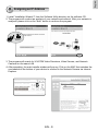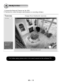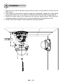
1
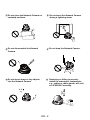
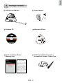
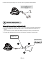
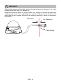
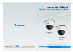
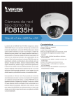
FD8133V/8134V
Fixed Dome
Network Camera
Quick Installation Guide
English
6F, No.192, Lien-Cheng Rd., Chung-Ho, New Taipei City, 235, Taiwan, R.O.C.
|T: +886-2-82455282| F: +886-2-82455532| E: [email protected]
VIVOTEK Netherlands B.V.
Busplein 36, 1315KV, Almere, The Netherlands
|T: +31 (0)36 5389 149| F: +31 (0)36 5389 111| E: [email protected]
簡中
日本語
Français
FD8133V: 3-axis • ePTZ
IFD8134V: IR Illuminators
P/N:625013703G Rev. 1.3
All specifications are subject to change without notice.
Copyright c 2014 VIVOTEK INC. All rights reserved.
VIVOTEK INC.
繁中
VIVOTEK USA, INC.
2050 Ringwood Avenue, San Jose, CA 95131
|T: 408-773-8686| F: 408-773-8298| E: [email protected]
Español
Deutsch
Português
Italiano
Türkçe
Polski
Русский
Česky
Svenska
English
Warning Before Installation
Power off the Network Camera as
soon as smoke or unusual odors are
detected.
Contact your distributor in the event of
occurrence.
Keep the Network Camera away
from water. If the Network Camera
becomes wet, power off immediately.
Contact your distributor in the event of
occurrence.
Do not place the Network Camera
around heat sources, such as a
television or oven.
Refer to your user's manual for the
operating temperature.
Keep the Network Camera away from
direct sunlight.
Do not place the Network Camera in
high humidity environments.
EN - 1
Do not place the Network Camera on
unsteady surfaces.
Do not touch the Network Camera
during a lightning storm.
Do not disassemble the Network
Camera.
Do not drop the Network Camera.
Do not insert sharp or tiny objects
into the Network Camera.
Replacing or failing to properly
install the waterproof components,
e.g., cables or cable glands, will void
our IP65/66/67 warranty.
EN - 2
English
1
Package Contents
FD8133V or FD8134V
Power Adapter
Software CD
Alignment Sticker
Drill hole
Cable hole
500024701G
Cable hole
Drill h
ole
Quick Installation Guide /
Warranty Card
RJ45 Female/Female Coupler /
Screwdriver/ Screws / Clamp Core
EN - 3
2
Physical Description
Light Sensor
Lens
MicroSD/SDHC
Card Slot
Black Cover
IR LEDs (8 units, distance 10m)
(FD8134V only)
General I/O Terminal Block
Ethernet 10/100
RJ45 Plug
Reset Button
Power Cord Socket
Status LED
3
Hardware Installation
First, follow the instructions below to remove the dome cover.
Dome Cover
Network Camera
Model No: FD8134V
MAC:0002D107258A
V I
RoHS
This device complies with part 15 of the FCC rules. Operation is subject to the following two conditions:
(1)This device may not cause harmful interference, and
(2) this device must accept any interference received, including interference that may cause undesired operation.
Pat. 6,930,709
Made in Taiwan
Record the MAC address before
installing the camera.
EN - 4
English
Then remove the black cover as shown below.
Tilt Adjustment Screw
A
oh
el
oh
el
rD
li
C
ba
el
oh
el
C
ba
el
h llir
o
el
Ceiling Mount
D
e
Dril hol
A
e
Cable hol
e
Cable hol
Drill hole
Wall Mount
1.Attach the alignment sticker to the ceilling/wall.
2.Through the two circles on the sticker, drill two pilot holes into the
ceilling/wall.
3. The Network Camera can be mounted with the cable routed
through the ceiling/wall or from the side. If you want to feed the
cable through the ceiling/wall, drill a cable hole A as shown in the
above picture.
4.Hammer the supplied plastic anchors into the holes.
5.Align the two holes on each side of the camera base with the two
plastic anchors on the ceilling/wall, insert the supplied screws to
corresponding holes and secure them with a screwdriver.
EN - 5
6.Buckle the supplied clamp core onto the cable to against the EMI radiation.
The clamp core should be away
from the device at least 5 cm.
5 cm
4
Network Deployment
General Connection (without PoE)
1.If you have external DI devices, make the connection from general I/O terminal block.
2. Use the supplied RJ45 female/female coupler to connect the Network Camera to a
switch.
Use a Category 5 Cross Cable when Network Camera is directly connected to PC.
3.Connect the supplied power cable from the Network Camera to a power outlet.
+ : Digital input
- : Digital input
Ethernet Switch
POWER
1
2
3
EN - 6
COLLISION
1
2
3
4
5
LINK
RECEIVE
PARTITION
English
Power over Ethernet (PoE) (FD8134V only)
When using a PoE-enabled switch
This Network Camera is PoE-compliant, allowing transmission of power and data via a
single Ethernet cable. Follow the below illustration to connect the Network Camera to a
PoE-enabled switch via Ethernet cable.
POWER
COLLISION
1
2
3
4
LINK
RECEIVE
PARTITION
5
PoE Switch
When using a non-PoE switch
Use a PoE power injector (optional) to connect between the Network Camera and a
non-PoE switch.
PoE Power Injector
(optional)
POWER
COLLISION
1
2
3
4
5
Non-PoE Switch
EN - 7
LINK
RECEIVE
PARTITION
IMPORTANT!
lthough the camera and the cable gland on the camera's end are waterproof, the cable
A
molding at the other end is not waterproof.
Measures should be taken to prevent water from leaking in through the cable-end
molding, such as the use of expanding foam sealant, putties, and so on. Note that the
cable gland on the camera should also be securely fastened to attain its waterproof
functionality.
Waterproof
Not Waterproof
Cable Molding
EN - 8
English
5 Assigning an IP Address
1.Install “Installation Wizard 2” from the Software Utility directory on the software CD.
2.The program will conduct an analysis of your network environment. After your network is
analyzed, please click on the “Next” button to continue the program.
Installation
Wizard 2
3.The program will search for VIVOTEK Video Receivers, Video Servers, and Network
Cameras on the same LAN.
4.After searching, the main installer window will pop up. Click on the MAC that matches the
one labeled on the bottom of your device to connect to the Network Camera via Internet
Explorer.
Network Camera
Model No: FD8134V
00-02-D1-07-25-8A
MAC:0002D107258A
V I
RoHS
This device complies with part 15 of the FCC rules. Operation is subject to the following two conditions:
(1)This device may not cause harmful interference, and
(2) this device must accept any interference received, including interference that may cause undesired operation.
Pat. 6,930,709
192.168.5.151
0002D107258A
Made in Taiwan
EN - 9
FD8134
6
Ready to Use
1.Access the Network Camera on the LAN.
2.Retrieve live video through a web browser or recording software.
For further setup, please refer to the user's manual on the software CD.
EN - 10
English
7
Adjusting the Lens
Based on the live image retrieved from the camera, adjust the camera lens to the desired
viewing angle:
1. Turn the lens module left and right.
2.Loosen the tilt adjustment screws on both sides of the camera and then turn the lens
module up and down. Upon completion, tighten the screws.
3. Turn the lens to adjust the image orientation.
Rotate the screw
Turn the lens
Pan 350°
1
Loosen
Tighten
2
3
Tilt:
Rotate 350°
FD8133V: 85°
FD8134V: 70°
3-axis Mechanism Design
The sophisticated 3-axis mechanism design offers very flexible, easy hardware installation
for either ceiling or wall mount.
Pan 350°
Tilt Adjustment Screw
Rotate 350°
DO NOT over rotate the lens. Doing
so will damage the camera lens
module.
Tilt:
FD8133V: 85°
FD8134V: 70°
EN - 11
8
Completion
1. Align the inner side of the black cover with the notch on both sides of the lens, fix the
black cover.
2. If you choose to the feed the cable through the ceiling/wall, arrange the cable neatly
through the cable hole. If you choose to feed the cable from the side, remove plate B.
3. Attach the dome cover to the camera as the direction shown below. With idiot-proof
mechanism design, the dome cover cannot be attatched if the angle does not fit.
4. Finally, make sure all parts of the camera are securely installed.
2
Be aware of the
cable route!
1
B
3
EN - 12
FD8133V/8134V
Fixed Dome
Network Camera
Quick Installation Guide
English
6F, No.192, Lien-Cheng Rd., Chung-Ho, New Taipei City, 235, Taiwan, R.O.C.
|T: +886-2-82455282| F: +886-2-82455532| E: [email protected]
VIVOTEK Netherlands B.V.
Busplein 36, 1315KV, Almere, The Netherlands
|T: +31 (0)36 5389 149| F: +31 (0)36 5389 111| E: [email protected]
簡中
日本語
Français
FD8133V: 3-axis • ePTZ
IFD8134V: IR Illuminators
P/N:625013703G Rev. 1.3
All specifications are subject to change without notice.
Copyright c 2014 VIVOTEK INC. All rights reserved.
VIVOTEK INC.
繁中
VIVOTEK USA, INC.
2050 Ringwood Avenue, San Jose, CA 95131
|T: 408-773-8686| F: 408-773-8298| E: [email protected]
Español
Deutsch
Português
Italiano
Türkçe
Polski
Русский
Česky
Svenska