1
SAFETY PRECAUTIONS
► Read this manual thoroughly before using LGIS equipment. Also, pay
careful attention to safety and handle the module properly.
► Safety precautions are for using the product safely and correctly in order to
prevent the accidents and danger, so make sure to follow all directions in
safety precautions.
► The precautions are divided into 2 sections, ‘Warning’ and ‘Caution’. Each
of the meaning is represented as follows
Warning
Indicates that incorrect handling may cause hazardous
conditions, resulting in death or severe injury.
Caution
Indicates that incorrect handling may cause hazardous
conditions, resulting in medium or slight personal injury
or physical damage.
► The symbols which are indicated in the PLC and User’s Manual mean as
follows;
This symbol means paying attention because of danger in specific
situations.
This symbol means paying attention because of danger of electrical
shock.
► Store this manual in a safe place so that you can take it out and read it
whenever necessary. Always forward it to the end user.
SAFETY PRECAUTIONS
Design Precautions
Warning
Install a safety circuit external to the PLC that keeps the entire system
safe even when there are problems with the external power supply or
the PLC module. Otherwise, serious trouble could result from
erroneous output or erroneous operation.
- Outside the PLC, construct mechanical damage preventing interlock
circuits such as emergency stop, protective circuits, positioning upper
and lower limits switches and interlocking forward/reverse operation.
When the PLC detects the following problems, it will stop calculation and
turn off all output in the case of watchdog timer error, module interface
error, or other hardware errors.
However, one or more outputs could be turned on when there are
problems that the PLC CPU cannot detect, such as malfunction of output
device (relay, transistor, etc.) itself or I/O controller. Build a fail safe
circuit exterior to the PLC that will make sure the equipment operates
safely at such times. Also, build an external monitoring circuit that will
monitor any single outputs that could cause serious trouble.
Make sure all external load connected to output does NOT exceed the
rating of output module.
Overcurrent exceeding the rating of output module could cause fire, damage
or erroneous operation.
Build a circuit that turns on the external power supply when the PLC
main module power is turned on.
If the external power supply is turned on first, it could result in erroneous
output or erroneous operation.
SAFETY PRECAUTIONS
Design Precautions
Caution
Do not bunch the control wires or communication cables with the main
circuit or power wires, or install them close to each other. They should
be installed 100mm (3.94inch) or more from each other.
Not doing so could result in noise that would cause erroneous operation.
Installation Precautions
Caution
Use the PLC in an environment that meets the general specification
contained in this manual or datasheet.
Using the PLC in an environment outside the range of the general
specifications could result in electric shock, fire, erroneous operation, and
damage to or deterioration of the product.
Completely turn off the power supply before loading or unloading the
module.
Not doing so could result in electric shock or damage to the product.
Make sure all modules are loaded correctly and securely.
Not doing so could cause a malfunction, failure or drop.
Make sure I/O and extension connector are installed correctly.
Poor connection could cause an input or output failure.
When install the PLC in environment of much vibration, be sure to
insulate the PLC from direct vibration.
Not doing so could cause electric shock, fire, and erroneous operation.
Be sure to there are no foreign substances such as conductive debris
inside the module.
Conductive debris could cause fires, damage, or erroneous operation.
SAFETY PRECAUTIONS
Wiring Precautions
Warning
Completely turn off the external power supply when installing or
placing wiring.
Not doing so could cause electric shock or damage to the product.
Make sure that all terminal covers are correctly attached.
Not attaching the terminal cover could result in electric shock.
Caution
Be sure that wiring is done correctly be checking the product’s rated
voltage and the terminal layout.
Incorrect wiring could result in fire, damage, or erroneous operation.
Tighten the terminal screws with the specified torque.
If the terminal screws are loose, it could result in short circuits, fire, or
erroneous operation.
Be sure to ground the FG or LG terminal to the protective ground
conductor.
Not doing so could result in erroneous operation.
Be sure there are no foreign substances such as sawdust or wiring
debris inside the module.
Such debris could cause fire, damage, or erroneous operation.
SAFETY PRECAUTIONS
Startup and Maintenance Precautions
Warning
Do not touch the terminals while power is on.
Doing so could cause electric shock or erroneous operation.
Switch all phases of the external power supply off when cleaning the
module or retightening the terminal or module mounting screws.
Not doing so could result in electric shock or erroneous operation.
Do not charge, disassemble, heat, place in fire, short circuit, or solder
the battery.
Mishandling of battery can cause overheating or cracks which could result in
injury and fires.
Caution
Do not disassemble or modify the modules.
Doing so could cause trouble, erroneous operation, injury, or fire.
Switch all phases of the external power supply off before mounting or
removing the module.
Not doing so could cause failure or malfunction of the module.
Use a cellular phone or walky-talky more than 30cm (11.81 inch) away
from the PLC
Not doing so can cause a malfunction.
Disposal Precaution
Caution
When disposing of this product, treat it as industrial waste.
Not doing so could cause poisonous pollution or explosion.
Revision History
Issue date
‘02. 05.
•
Manual No.
Revised Contents
First edition of Smart I/O module publishied.
User’s Manual No. is inscribed on the right bottom side of the back cover.
INDEX
Chapter 1
Overview
1.1 How to use the User’s Manual------------------------------------------------------------------------------ 1-1
1.2 Characteristics of Smart I/O--------------------------------------------------------------------------------- 1-2
1.3 Product Configuration of Smart I/O ----------------------------------------------------------------------- 1-3
1.3.1 Type name indication-------------------------------------------------------------------------------- 1-3
1.3.2 Characteristics per module----------------------------------------------------------------------- 1-4
1.3.3 Version Compatibility Table per Smart I/O module ------------------------------------------ 1-6
Chapter 2
Product Specification
2.1 General Specification----------------------------------------------------------------------------------------- 2-1
2.2 Power Specification-------------------------------------------------------------------------------------------- 2-2
2.2.1 Performance Specification------------------------------------------------------------------------- 2-2
2.3 Digital Input Module Specification-------------------------------------------------------------------------- 2-3
2.3.1 DC 16 point input module : GPL/GDL/GRL/GSL-D22A ---------------------------------- 2-3
2.3.1 DC 32 point input module : GPL/GDL/GRL/GSL-D24A ----------------------------------- 2-4
2.4 Digital Output Module Specification------------------------------------------------------------------------2-5
2.4.1 16 point relay output module : GPL/GDL/GRL/GSL-RY2A ------------------------------- 2-5
2.4.2 16 point transistor output module : GPL/GDL/GRL/GSL-TR2A ------------------------ 2-6
2.4.3 32 point transistor output module : GPL/GDL/GRL/GSL-TR4A ------------------------- 2-7
2.5 Digital I/O combined Module Specification-------------------------------------------------------------- 2-8
2.5.1 32point I/O combined module (DC16/TR16 point) : GPL/GDL/GFL/GSL-DT4A ---- 2-8
2.6 Communication Module Specification-------------------------------------------------------------------- 2-9
2.6.1 Profibus-DP module specification---------------------------------------------------------------- 2-9
2.6.2 DeviceNet module specification------------------------------------------------------------------ 2-9
2.6.3 Rnet module specification ---------------------------------------------------------------------- 2-10
2.6.4 Modbus module specification------------------------------------------------------------------- 2-10
2.7 Communication Cable Specification -------------------------------------------------------------------- 2-11
2.7.1 Profibus-DP cable specification---------------------------------------------------------------- 2-11
2.7.2 DeviceNet cable specification------------------------------------------------------------------ 2-12
2.7.3 Rnet cable specification-------------------------------------------------------------------------- 2-14
2.7.4 Modbus cable specification--------------------------------------------------------------------- 2-15
2.8 Terminating----------------------------------------------------------------------------------------------2.8.1 Profibus-DP terminating---------------------------------------------------------------------2.8.2 DeviceNet terminating-----------------------------------------------------------------------2.8.3 Rnet terminating-------------------------------------------------------------------------------2.8.4 Modbus terminating---------------------------------------------------------------------------
Chapter 3
2-16
2-16
2-16
2-17
2-18
System Configuration
3.1 Notices in selecting module--------------------------------------------------------------------------------- 3-1
3.2 Names of Each Part-------------------------------------------------------------------------------------- 3-2
3.2.1 Basic system configuration------------------------------------------------------------------------ 3-2
3.2.2 Names of each part of Smart I/O series---------------------------------------------------- 3-3
3.3 I/O Wiring Diagram of Communication Module--------------------------------------------------------- 3-9
3.3.1 External connection diagram of Smart I/O module----------------------------------------- 3-9
3.4 Examples of System Configuration---------------------------------------------------------------------3.4.1 Profibus-DP system------------------------------------------------------------------------------3.4.2 DeviceNet system -------------------------------------------------------------------------------3.4.3 Rnet system ---------------------------------------------------------------------------------------3.4.4 Modbus system ------------------------------------------------------------------------------------
3-17
3-17
3-18
3-19
3-20
Chapter 4
Communication Programming
4.1 Overview------------------------------------------------------------------------------------------------------- 4-1
4.2 High Speed Link------------------------------------------------------------------------------------------------ 4-3
4.2.1 Overview-------------------------------------------------------------------------------------------------- 4-3
4.2.2 High Speed Link sending/receiving data processing------------------------------------------ 4-4
4.2.3 Operation order by High Speed Link-------------------------------------------------------------- 4-5
4.2.4 GMWIN’s setting of High Speed Link------------------------------------------------------------ 4-6
4.2.5 KGLWIN Link parameter setting------------------------------------------------------------------ 4-14
4.2.6 High Speed Link Communication status flag information----------------------------------- 4-18
4.2.7 High Speed Link Speed calculation-------------------------------------------------------------- 4-21
4.3 Function Block------------------------------------------------------------------------------------------------- 4-25
4.3.1 Overview------------------------------------------------------------------------------------------------- 4-25
4.3.2 Start of GMWIN Function Block-------------------------------------------------------------------- 4-25
4.3.3 Execution of KGLWIN command------------------------------------------------------------------ 4-27
Chapter 5
Profibus-DP Communication
5.1 Overview-------------------------------------------------------------------------------------------------------- 5-1
5.2 Communication Specification------------------------------------------------------------------------------- 5-1
5.3 Basic Performance--------------------------------------------------------------------------------------------- 5-2
5.3.1 Overview----------------------------------------------------------------------------------------------- 5-2
5.3.2 Operation by High Speed Link ------------------------------------------------------------------- 5-2
5.3.3 SyCon ----------------------------------------------------------------------------------------------- 5-3
5.3.4 Insertion of master module------------------------------------------------------------------------ 5-4
5.3.5 Master module setting------------------------------------------------------------------------------ 5-5
5.3.6 Insertion of slave------------------------------------------------------------------------------------ 5-6
5.3.7 Slave Configuration -------------------------------------------------------------------------------- 5-7
5.3.8 Bus parameter setting------------------------------------------------------------------------------ 5-8
5.3.9 Device allocation---------------------------------------------------------------------------------- 5-9
5.3.10 Configuration download - ---------------------------------------------------------------------- 5-11
5.3.11 High Speed Link parameter setting in GMWIN-------------------------------------------- 5-12
5.3.12 High Speed Link information in GMWIN----------------------------------------------------- 5-16
5.3.13 High Speed Link parameter setting in KGLWIN------------------------------------------- 5-20
Chapter 6
DeviceNet Communication
6.1 Overview------------------------------------------------------------------------------------------------------- 6-1
6.2 Communication Specification------------------------------------------------------------------------------- 6-2
6.3 Communication Parameter Setting------------------------------------------------------------------------ 6-3
6.3.1 High Speed Link service---------------------------------------------------------------------------- 6-4
6.4 Program Examples------------------------------------------------------------------------------------------- 6-12
6.4.1 GLOFA-GM series---------------------------------------------------------------------------------- 6-12
6.4.2 MASTER-K series -------------------------------------------------------------------------------- 6-16
Chapter 7
Rnet Communication
7.1 Overview------------------------------------------------------------------------------------------------------ 7-1
7.2 Communication Specification------------------------------------------------------------------------------ 7-1
7.3 Communication Parameter Setting----------------------------------------------------------------------- 7-2
7.3.1 Overview-------------------------------------------------------------------------------------------- 7-2
7.3.2 High Speed Link communication status flag-------------------------------------------------- 7-3
7.3.3 GMWIN High Speed Link setting----------------------------------------------------------------- 7-3
7.3.4 KGLWIN Link setting------------------------------------------------------------------------------- 7-12
7.4 Program Examples------------------------------------------------------------------------------------------- 7-22
7.4.1 GLOFA-GM series -------------------------------------------------------------------------------- 7-22
7.4.2 MASTER-K series -------------------------------------------------------------------------------- 7-24
Chapter 8
Modbus Communication
8.1 Overview-------------------------------------------------------------------------------------------------------- 8-1
8.2 Communication Specification------------------------------------------------------------------------------- 8-1
8.3 Communication Parameter Setting----------------------------------------------------------------------- 8-6
8.3.1 GLOFA-GM series ---------------------------------------------------------------------------------- 8-6
8.3.2 MASTER-K series ----------------------------------------------------------------------------------- 8-9
8.4 Function Block------------------------------------------------------------------------------------------------- 8-11
8.4.1 GLOFA-GM series -------------------------------------------------------------------------------- 8-11
8.4.2 MASTER-K series -------------------------------------------------------------------------------- 8-32
8.5 Program Examples------------------------------------------------------------------------------------------- 8-34
8.5.1 GLOFA-GM series -------------------------------------------------------------------------------- 8-34
8.5.2 MASTER-K series -------------------------------------------------------------------------------- 8-44
Chapter 9
Installation & Wiring
9.1 Installation------------------------------------------------------------------------------------------------------- 9-1
9.1.1 Installation Environment---------------------------------------------------------------------------- 9-1
9.1.2 Notices in installing Profibus-DP module------------------------------------------------------- 9-2
9.1.3 Notices in installing DeviceNet module-------------------------------------------------------- 9-3
9.1.4 Notices in installing Rnet module--------------------------------------------------------------- 9-8
9.1.5 Notices in installing Modbus module----------------------------------------------------------- 9-9
9.1.6 Notices in Handling------------------------------------------------------------------------------- 9-10
9.2 Wiring----------------------------------------------------------------------------------------------------------9.2.1 Power wiring---------------------------------------------------------------------------------------9.2.2 I/O Machine Wiring-------------------------------------------------------------------------------9.2.3 Grounding wiring----------------------------------------------------------------------------------9.2.4 Cable specification for wiring-------------------------------------------------------------------
9-14
9-14
9-16
9-16
9-17
Chapter 10
Maintenance and Repair
10.1 Repair and Check------------------------------------------------------------------------------------------ 10-1
10.2 Daily Check-------------------------------------------------------------------------------------------------- 10-2
10.3 Regular Check---------------------------------------------------------------------------------------------- 10-4
Chapter 11 Trouble Shooting
11.1 Basic Procedure of Trouble Shooting----------------------------------------------------------------- 11-1
11.2 Trouble Shooting-------------------------------------------------------------------------------------------- 11-2
11.2.1 Action method when POWER LED is OFF ------------------------------------------------ 11-3
11.2.2 Action method when ERR LED is blinking-------------------------------------------------- 11-4
11.2.3 Action method when RUN LED is OFF ----------------------------------------------------- 11-5
11.2.4 Action method when I/O part does not work normally------------------------------------ 11-6
11.2.5 Action method when Program Write does not work -------------------------------------- 11-8
11.3 Trouble Shooting Questionnaire------------------------------------------------------------------------- 11-9
Appendix
A.1 Communication Terminology------------------------------------------------------------------------------ A-1
A1.1 Profibus-DP -------------------------------------------------------------------------------------------- A-1
A1.2 DeviceNet ----------------------------------------------------------------------------------------------- A-3
A1.3 Rnet ------------------------------------------------------------------------------------------------------- A-4
A1.4 Modbus --------------------------------------------------------------------------------------------------- A-6
A.2 External Dimension------------------------------------------------------------------------------------------- A-7
Chapter 1 Overview
Chapter 1 Overview
1.1 How to use the User’s Manual
This User’s Manual provides the information such as product specification, performance and
operation method needed to use PLC System composed of Smart I/O module.
The User’s Manual is composed of as follows.
CHAP.1 Overview
Here describes the configuration of the user’s manual, product characteristics and
terminology.
CHAP.2 Product Specification
Here describes common specification of each product used for Smart I/O series.
CHAP.3 System Configuration
Here describes the kinds of product available for Smart I/O series and system
configuration method.
CHAP.4 Communication Programming
Here describes common communication program operation method to act Smart I/O
module.
CHAP.5 Profibus-DP Communication
Here describes basic communication method of Profibus-DP(Pnet) communication
module.
CHAP.6 DeviceNet Communication
Here describes basic communication method of DeviceNet(Dnet) communication module.
CHAP.7 Rnet Communication
Here describes basic communication method of FIELDBUS(RNET) communication
module.
CHAP.8 Modbus Communication
Here describes basic communication method of Modbus(Snet) communication module.
CHAP.9 Installation and Wiring
Here describes installation and wiring method, and notices to make sure of the reliability
of PLC system.
CHAP.10 Maintenance and Repair
Here describes check list and method to run PLC system normally for a long term.
CHAP.11 Trouble Shooting
Here describes various errors to be occurred while using the system and the action to
solve the problem.
Appendix
Here describes the product terminology and external dimension for system installation.
1-1
Chapter 1 Overview
1.2 Characteristics of Smart I/O
1) The characteristics of Smart I/O series is as follows.
(1) Product design based on International Electrotechnical Commission (IEC 61131) (GLOFA
series in common)
y Easy support to programming device
y Standard language (IEC 61131-3) provided (IL / LD / SFC)
(2) Open network by selecting international standard communication protocol.
(3) Available to communicate with remote master module independently without power
module/CPU module.
(4) Available to set maximum 32 ~ 64 stations.
- Maximum 64 stations (Rnet,Dnet)
- Maximum 32 stations (Pnet,Snet)
(5) Enables to save the cost for installation and maintenance.
(6) Various system configuration and simple maintenance and repair.
(7) Easy to change the system.
(8) Compatible with other maker’s product.
- Available to connect Smart I/O to other maker’s master.
(9) Easy to set the system as the station address setting by hardware is available.
(10) Simple communication programming.
- Using the GMWIN/KGLWIN high speed link parameter
- But for Modbus, using function block
(11) Supports various I/O.
- DC input 16/32 points, TR output 16/32 points, Relay output 16 points
(12) Supports various OPEN type communication method.
- Profibus-DP, DeviceNet, Rnet, Modbus
(13) Easy to configure and use as integrating PLC.
- Packaged by one unit including CPU, I/O and communication function.
(14) Provides the online network status detection function.
- Available to know the remote module status through high speed link monitor.
(15) Supports high speed communication.
(16) Flexible communication relation is available as the speed shall be set automatically
according to the speed of master.
- Profibus-DP, DeviceNet etc.
1-2
Chapter 1 Overview
1.3 Product Configuration of Smart I/O
1.3.1 Type Name Indication
Classification
Model name
Type name indication
GPL-D22A
16
point
GDL-D22A
GRL-D22A
GSL-D22A
DC
Input
GPL-D24A
G
L : Communi
Char.
class
cation
GDL-D24A
32 point
GRL-D24A
GSL-D24A
GPL-TR2A
Communication type
I/O points
P : Profibus-DP
2 : 16 points
D : DeviceNet
4 : 32 points
R : Rnet
GDL-TR2A
16 point
S : Modbus
I/O Type
GRL-TR2A
D2 : DC24V input
TR
GSL-TR2A
RY : Relay output
output
GPL-TR4A
TR : TR output
DT : DC input/ TR
output
GDL-TR4A
32 point
GRL-TR4A
GSL-TR4A
GPL-RY2A
RY
Output
GDL-RY2A
16 point
GRL-RY2A
GSL-RY2A
GPL-DT4A
DC/TR
combined
GDL-DT4A
32 point
GRL-DT4A
GSL-DT4A
1-3
Chapter 1 Overview
1.3.2 Characteristics per Module
Classifi
cation
Product Name
Type name
GPL-TR2A
• Input voltage(power section) : DC24V(rating)
• I/O point : Transistor output 16 points
GPL-TR4A
• Input voltage(power section) : DC24V(rating)
• I/O point : Transistor output 32 points
GPL-DT4A
• Input voltage(power section) : DC24V(rating)
• I/O point(combined) : DC input 16 points/ TR output 16
points
GPL-RY2A
• Input voltage(power section) : DC24V(rating)
• I/O point : Relay output 16 points
GPL-D22A
• Input voltage(power section) : DC24V(rating)
• I/O point : DC input 16 points
GPL-D24A
• Input voltage(power section) : DC24V(rating)
• I/O point : DC input 32 points
GDL-TR2A
• Input voltage(power section) : DC24V(rating)
• I/O point : Transistor output 16 points
GDL-TR4A
• Input voltage(power section) : DC24V(rating)
• I/O point : Transistor output 32 points
GDL-DT4A
• Input voltage(power section) : DC24V(rating)
• I/O point(combined) : DC input 16 points/ TR output 16
points
GDL-RY2A
• Input voltage(power section) : DC24V(rating)
• I/O point : Relay output 16 points
GDL-D22A
• Input voltage(power section) : DC24V(rating)
• I/O point: DC input 16 points
GDL-D24A
• Input voltage(power section) : DC24V(rating)
• I/O point: DC input 32 points
GSL-TR2A
• Input voltage(power section) : DC24V(rating)
• I/O point : Transistor output 16 points
GSL-TR4A
• Input voltage(power section) : DC24V(rating)
• I/O point : Transistor output 32 points
GSL-DT4A
• Input voltage(power section) : DC24V(rating)
• I/O point(combined) : DC input 16 points/ TR output 16
points
GSL-RY2A
• Input voltage(power section) : DC24V(rating)
• I/O point : Relay output 16 points
GSL-D22A
• Input voltage(power section) : DC24V(rating)
• I/O point : DC input 16 points
GSL-D24A
• Input voltage(power section) : DC24V(rating)
• I/O point : DC input 32 points
Profibus-DP
Smart
I/O
Specification
DeviceNet
Modbus
1-4
Chapter 1 Overview
Classifi
cation
Smart
I/O
Product name
Type name
Specification
GRL-TR2A
• Input voltage(power section) : DC24V(rating)
• I/O point : Transistor output 16 points
GRL-TR4A
• Input voltage(power section) : DC24V(rating)
• I/O point : Transistor output 32 points
GRL-DT4A
• Input voltage(power section) : DC24V(rating)
• I/O point(combined) : DC input 16 points / TR output 16
points
GRL-RY2A
• Input voltage(power section) : DC24V(rating)
• I/O point : Relay output 16 points
GRL-D22A
• Input voltage(power section) : DC24V(rating)
• I/O point : DC input 16 points
GRL-D24A
• Input voltage(power section) : DC24V(rating)
• I/O point: DC input 32 points
Rnet
1-5
Chapter 1 Overview
1.3.3 Version Compatibility Table per Smart I/O Module
The followings describe the list that enables the compatibility of O/S version between various
CPU and master module to use Smart I/O series.
Before using the product, please refer to the list below and apply it to system configuration.
Classification
CPU
PADT
Smart I/O
Master
Model type
Available O/S
GM3
More than Version 2.5
GM4
More than Version 2.6
GM6
More than Version 1.9
GM7
More than Version 1.6
K1000S
More than Version 3.1
K300S
More than Version 3.1
K200S
More than Version 2.2
K80S
More than Version 1.6
GMWIN
More than Version 3.6
KGLWIN
More than Version 3.3
Profibus-DP
More than Version 1.0
DeviceNet
More than Version 1.2
Rnet
More than Version 1.0
Modbus
More than Version 2.0
1-6
Chapter 2 Product Specification
Chapter 2 Product Specification
2.1 General Specification
The General Specification of Smart I/O series is as follows.
No
Items
Specification
References
0 ~ 55 °C
1
Use temperature
2
Storage Temp.
3
Use humidity
5 ~ 95%RH, no dew
4
Storage humidity
5 ~ 95%RH, no dew
−25 ~ +70 °C
In case of Intermittent vibration
Frequency
5
Vibration-resistant
-
Acceleration
Amplitude
10 ≤ f < 57Hz
−
2
57 ≤ f ≤ 150Hz
9.8m/s {1G}
In case of Continuous vibration
Frequency
Acceleration
10 ≤ f < 57Hz
−
2
57 ≤ f ≤ 150Hz
4.9m/s {0.5G}
0.075mm
−
Amplitude
0.035mm
−
Times
X, Y, Z
10 times
each direction
IEC6 1131-2
• max. impact acceleration : 147 m/s {15G}
• Application time : 11ms
• pulse wave type : semi-sine wave pulse (3 times each direction X, Y, Z)
IEC 61131-2
Square wave
impulse noise
LG 산전내부
시험규격기준
2
6
Impact-proof
7
Noise-resistant
Electrostatic
discharge
Radiant
electromagnetic
field noise
Fast
Transient
/ Bust
Noise
AC : ± 1,500 V,
DC : ±900 V
Voltage : 4kV (Touch discharge)
IEC 61131-2,
IEC 801-2
27 ~ 500 MHz, 10 V/m
IEC 61131-2,
IEC 801-3
Classifi
cation
Power
module
Voltage
2kV
8
Surrounding
environment
No corrosive gas, no dust
9
Use altitude
Less than 2,000m
10
Pollution
11
Cooling method
Digital I/O
(more than
24V )
1kV
Digital I/O (below 24V)
Analog I/O
Communication Interface
IEC 61131-2
IEC 801-4
0.25kV
Less than 2
Natural air-conditioning
Remark
1) IEC(International Electrotechnical Commission)
civil community that promotes international cooperation for standardization of electric/
제 4 장: International
CPU 모듈
electro technology, publishes international standard and operates suitability assessment system
related to the abov.
2) Pollution Degree
: An index that indicates the pollution degree of used environment that determines the
insulation performance of the device. For example, pollution degree 2 means the state to
occur the pollution of non-electric conductivity generally, but the state to occur temporary
electric conduction according to the formation of dew.
.
2-1
Chapter 2 Product Specification
2.2 Power Specification
Here describes the Power Specification of Smart I/O.
2.2.1 Performance Specification
Here describes Power Performance Specification of Smart I/O Profibus-DP(Pnet) module.
Specification
Items
GPLTR2A
GPLTR4A
GPLRY2A
GPLDT4A
GPLD22A
Input power
DC +24V (Max +28V, Min +19V)
Input current
0.4A(+24VDC)
Dash current
Less than 40A : (24VDC input)
Rated output current
(+5V)
0.2~0.6A
Rated output current
(+5V, Aux)
0.02~0.1A
Efficiency
More than 60% (in case of Full Load)
Power indication
When power input, LED ON
Output voltage dwell
time
Within 150ms (DC19~24V input, Full Load)
Suitable wire spec
1.5 ~ 2.5mm2 (AWG16 ~ 22)
Suitable tightening
torque
12kg cm
GPLD24A
Here describes Power Performance Specification of Smart I/O DeviceNet, Rnet, Modbus module.
Specification
Items
GD/R/SLTR2A
GD/R/SLTR4A
GD/R/SLRY2A
GD/R/SLDT4A
GD/R/SLD22A
Input power
DC +24V (Max +28V, Min +19V)
Input current
0.4A(+24VDC)
Dash current
Less than 40A : (24VDC input)
Rated output current
(+5V)
0.2~0.6A
Efficiency
More than 60% (in case of Full Load)
Power indication
When power input, LED ON
Output voltage dwell
time
Within 150ms (DC19~24V input, Full Load)
Suitable wire spec
1.5 ~ 2.5mm2 (AWG16 ~ 22)
Suitable tightening
torque
12kg cm
2-2
GD/R/SLD24A
Chapter 2 Product Specification
2.3 Digital Input Module Specification
2.3.1 DC16 point Input Module : GPL/GDL/GRL/GSL-D22A
Type name
DC input module
Spec.
Input point
16 points
Insulation method
Photo coupler insulation
Rated input voltage
DC24V
Rated input current
7 mA
Use voltage range
DC20.4 ~ 28.8V (ripple rate : within 5% )
Max. simultaneous input point
100% (16 points/1COM) simultaneously ON
ON voltage / ON current
More than DC19V / more than 3.5 mA
OFF voltage / OFF current
Less than DC6V / less than 1.5 mA
Input resistance
Approx. 3.3 kΩ
Response time
Off → On
Less than 3 ms
On → Off
Less than 3 ms
Common method
16 points / COM
Internal consumption current
Less than 200mA
Action indication
LED ON when input ON
External connection method
Terminal unit connector (M3 X 6 screws)
weight
Less than 160g
Circuit Configuration
DC5V
FG
Power circuit
DC24V
DC5V
R
Internal
circuit
Photo coupler
00
R
R
R
15
COM1
2-3
DC24V
Chapter 2 Product Specification
2.3.2 DC32 point Input Module : GPL/GDL/GRL/GSL-D24A
Type name
DC Input Module
Spec.
Input point
32 points
Insulation method
Photo coupler insulation
Rated input voltage
DC24V
Rated input voltage
7 mA
Use voltage range
DC20.4 ~ 28.8V (ripple rate : within 5% )
Max. simultaneous input point
100% (16 points/1COM) simultaneously ON
ON voltage / ON current
More than DC19V / more than 3.5 mA
OFF voltage / OFF current
Less than DC6V / less than 1.5 mA
Input resistance
Approx. 3.3 kΩ
Response time
Off -> On
Less than 3 ms
On - > Off
Less than 3 ms
Common method
16 points / COM
Internal consumption current
Less than 300 mA
Action indication
LED ON when input ON
External connection method
Terminal unit connector (M3 X 6 screws)
Weight
Less than 240g
Circuit Configuration
DC5V
FG
Power circuit
DC5V
DC24V
R
Internal
circuit
Photo coupler
00
R
R
R
15
COM0
DC5V
Internal
circuit
Photo coupler
R
DC24V
16
R
R
R
31
COM1
2-4
DC24V
Chapter 2 Product Specification
2.4 Digital Output Module Specification
2.4.1 16 point Relay Output Module : GPL/GDL/GRL/GSL-RY2A
Type name
Relay Output Module
Spec.
Output point
16 points
Insulation method
Relay insulation
Rated load voltage/current
DC24V 2A(resistance load) / 1point, AC220V 2A(COSΨ = 1)
Min.(max.) load voltage/current
DC5V / 1mA, AC250V, DC110V
Max. open/close frequency
1,200 times / hr
Surge killer
None
Mechanical
More than 20,000,000 times
Rated load voltage/current more than 100,000 times
Life
AC200V / 1.5A, AC240V / 1A (COSΨ = 0.7) more than 100,000
Electrical
AC200V / 1A,
AC240V / 0.5A (COSΨ = 0.35) more than 100,000
DC24V / 1A, DC100V / 0.1A (L / R = 7ms) more than 100,000
Response time
Off → On
Less than 10 ms
On → Off
Less than 12 ms
Common method
8 points / COM
Internal consumption current
Less than 550 mA (when all points ON)
Action indication
LED ON when output ON
External connection method
Terminal unit connector (M3 X 6 screws)
Weight
Less than 300g
Circuit Configuration
5V
Internal
power
FG
DC5V
Relay
Internal
circuit
L
00
AC110/220V
DC24V
Coil
TD62083
L
07
COMA
DC5V
Relay
Internal
circuit
AC110/220V
DC24V
L
08
AC110/220V
DC24V
Coil
TD62083
L
COMC
2-5
DC24V
15
AC110/220V
DC24V
Chapter 2 Product Specification
2.4.2 16 point Transistor Output Module : GPL/GDL/GRL/GSL-TR2A
Type name
Transistor Output Module
Spec.
Output point
16 points
Insulation method
Photo coupler insulation
Rated load voltage
DC 24V
Use load voltage range
DC 20.4 ~ 26.4V
Max. load current
0.1A / 1point, 2A / 1COM
Leakage current when OFF
Less than 0.1mA
Max. inrush current
Less than 4A / 10 ms
Max. voltage falling when ON
DC 1.5V
Surge killer
Clamp diode
Response time
Off → On
Less than 2 ms
On → Off
Less than 2 ms
Common method
16 points / 1COM
Internal consumption current
Less than 280 mA (when all points ON)
External power
Voltage
DC24V ± 10% (ripple voltage : less than 4 Vp-p)
current
Less than 50 mA (DC24V per 1COM )
Supply
Action indication
LED ON when output ON
External connection method
Terminal unit connector (M3 X 6 screws)
Weight
Less than 160g
Circuit Configuration
DC5V
FG
Power circuit
DC24V
Internal
circuit
00
L
Photo coupler
R
R
Transistor
R
15
L
COM
DC24V
2-6
Chapter 2 Product Specification
2.4.3 32 point Transistor Output Module : GPL/GDL/GRL/GSL-TR4A
Type name
Transistor Output Module
Spec.
Output point
32 points
Insulation method
Photo coupler insulation
Rated load voltage
DC 24V
Use load voltage range
DC 20.4 ~ 26.4V
Max. load current
0.1A / 1point, 2A / 1COM
Leakage current when OFF
Less than 0.1 mA
Max. inrush current
Less than 0.4 A / 10 ms
Max. voltage falling when ON
DC 1.0 V
Response time
Off → On
Less than 2 ms
On → Off
Less than 2 ms
Common method
16 points / 1 COM
Internal consumption current
Less than 380 mA (when all points ON)
External power
supply
Voltage
current
DC 24V ± 10 % (ripple voltage : less than 4Vp-p )
40 mA (DC 24V per 1 COM)
LED ON when output ON (16 points indication conversion by selection
Action indication
switch)
External connection method
Terminal unit connector (M3 X 6 screws)
Weight
Less than 240g
Circuit Configuration
DC5V
FG
Power circuit
12
Internal
circuit
00
L
Photo coupler
R
R
Transistor
15
L
R
Internal
circuit
COM0
16
L
Photo coupler
R
R
Transistor
R
31
L
DC24V
COM1
2-7
Chapter 2 Product Specification
2.5 Digital I/O Combined Module Specification
2.5.1 32 point I/O Combined Module(DC16/TR16 point): GPL/GDL/GRL/GSLDT4A
I/O Combined Module
Input
Output
Input point
16 point
Output point
16 point
Insulation method
Photo coupler insulation
Insulation method
Photo coupler insulation
Rated input voltage
DC 24V
Rated load voltage
DC24V
Rated input current
7 mA
Max. load current
0.1A/1point, 2A/1COM
Max. load voltage/current
AC250V, DC125V
Leakage current when OFF
Less than 0.1 mA
DC20.4~26.4V
Use voltage range
(ripple rate : within 5%)
Max. simultaneous input point
100% simultaneously ON
ON voltage/ON current
DC19V/3.0 mA or more
Max. inrush current
Less than 4A/10ms
OFF voltage/OFF current
DC6V/1.5 mA or less
Surge killer
none
Input resistance
Approx. 3.3 kΩ
Response
Off → On
Less than 2 ms
Response
Off→ On
Less than 3 ms
time
On → Off
Less than 2 ms
On → Off
Less than 3 ms
time
Common method
16 points / COM
Common method
16 points / 1COM
Action indication
LED ON when input ON
Action indication
LED ON when output ON
External connection method
Terminal unit connector (M3×6 screws)
Internal consumption current
Less than 350 mA
Weight
Less than 240g
Circuit Configuration
DC5V
FG
Power circuit
Internal
circuit
DC24V
00
L
Photo coupler
R
R
Transistor
R
COM0
DC5V
R
Internal
circuit
Photo coupler
15
L
DC24V
00
R
R
R
15
COM1
DC24V
2-8
Chapter 2 Product Specification
2.6 Communication Module Specification
2.6.1 Profibus-DP Module Specification
Classification
Profibus-DP
Module Type
Remote slave
Standard
EN 50170 / DIN 19245
Interface
RS-485(Electric)
Medium Access
POLL
Topology
BUS
Encoding method
NRZ
Cable
Shielded Twisted Pair
1200m (9.6K ~187Kbps)
400m (500 Kbps)
Communication distance
200m (1.5 Mbps)
100m (3M ~ 12Mbps)
Max. node
126 stations
Max. node (per segment)
32 stations
Max. I/O data
64Byte
2.6.2 DeviceNet Module Specification
Classification
DeviceNet
Module type
Remote slave
Protocol
CAN Protocol
Medium Access
POLL
Topology
BUS
Cable
Class 2 Thick/Thin Cable(Allen-Bradley standard)
Communication speed
125/250/500 kbps
Communication distance(Thick)
500/250/100 m
Max. drop
length
125 kbps
6m(max. extension 156m)
250 kbps
6m(max. extension 78m)
500 kbps
6m(max. extension 39m)
Data packet
Network structure
0 ~ 8 Byte(64 Bits)
iTrunk/drop line
iPower within same network/ signal cable
Bus method
iMulti slave/ multi casting
iPeer-to-Peer method
iStrobe,Poll,COS/Cyclic method
Max. node
Max. 64 MAC ID
32 I/O per node (max. 2,048 I/O)
System type
Action voltage
Node insertion/removal in voltage ON
DC 24V
2-9
Chapter 2 Product Specification
2.6.3 Rnet Module Specification
Classification
Rnet
Allowable inspection power cut time
20ms
Communication speed
1Mbps
Communication method
Semi dual bit serial method
Synchronous method
Frame synchronous method
Transmission path method
BUS
Total extension distance
750m
No. of connecting station
64 stations (including master stations)
Modulation method
Manchester Biphase-L
Error control method
Retry by CRC-CCITT and Time Over
Connector connection
9-PIN plug type
Using cable
TWISTED PAIR SHIELDED CABLE
Max. communication point
3,840 Word (master base)
Max. sending point
1,920 Word(master base)
Max. block no. assignment
63
Max. point of Block unit
60 Word
2.6.4 Modbus Module Specification
Classification
Snet
Module type
Remote slave
Protocol
Modbus-RTU
Max. protocol size
8 Byte
Topology
BUS
Cable
TWISTED PAIR SHIELDED CABLE
Communication speed
2400 ~ 38,400 BPS
Communication distance
1 Km
Medium Access
POLL
Max. node
32 stations
Communication point
32 points
2-10
Chapter 2 Product Specification
2.7 Communication Cable Specification
2.7.1 Profibus-DP Cable Specification
• Belden Network Cable
Type : Network Components
Protocol : FMS-DP-PA
Certification : No
Order No. : 3076F, 3077F, 3079A
Classification
Twinax
AWG
22
Type
BC-Bare Copper
Insulation
PE-Polyethylen
Insulation strength
Shield
Capacitance
Characteristic
impedance
Number of core wire
0.035 (Inch)
Aluminum FoilPolyester Tape/Braid Shield
8500 ㎊/ft
150Ω
2 Core
2-11
Chapter 2 Product Specification
2.7.2 DeviceNet Cable Specification
• Cable Specification
Type name
Class 2 Thick/Thin Cable
Maker
Allen-Bradley
Cable type
Round
Rated output voltage
30V/100VA
Max. allowable current
100VA/24V or 4A
External diameter
12.2mm/6.9mm
Number of core wire
5 cores
Class 2 Thick Cable
Spool Size
50m
150m
300m
500m
Trunk/ drop
Simultaneous use
Class 2 Thin Cable
Spool Size
50m
150m
300m
600m
• Cable Signal Name
Smart I/O Dnet I/F module cable have 5 cores as follows. It is composed of Twist pair
cable for DC 24V power supply, twist pair cable for signal cable, shield cable etc. and both
Thick and Thin cable are available for trunk/drop line.
Cble color
Signal name
Description
While
CAN_H
Signal cable
Blue
CAN_L
Signal cable
Bare
Drain
Shield cable
Black
V-
Power cable
Red
V+
Power cable
• Max. transmission distance by Cable types
Max. distance
Transmission speed
Thick cable
Thin cable
125kbps
500m
100m
250kbps
250m
100m
500kbps
100m
100m
2-12
Chapter 2 Product Specification
<STRUCTURE>
Copper-film covered shield
Insulation covering
-Thick: Green
-Thin: Yellow
DC Power cable
-15AWG 19X28(Thick)
-22AWG 19X34(Thin)
Mylar Tape
Signal cable
(Blue/White)
-18AWG 19X30(Thick)
-24AWG 19X36(Thin)
2-13
Shielded cable
Chapter 2 Product Specification
2.7.3 Rnet Cable Specification
• Twist Pair Cable
Cable Description
Product name
Low Capacitance Lan Interface Cable
Type name
LIREV-AMESB
Specification
2*0.64 mm (GS 92-3032,22 AWG)
Maker
LG Cable
Electric characteristics
Items
Unit
Characteristics
Test condition
Conductor resistance
Ω/km
Less than 59
Normal temp.
Voltage-resistance(DC)
V/min
500V 1 min resist
In air
Insulation resistance
MEGA Ω-km
More than 1,000
Normal temp.
Capacitance
pF/m
Less than 45
1 kHz
Characteristic impedance
Ω
120 ± 12
10MHz
Appearance characteristics
Conductor
Insulator
No. of core wire
CORE
2
Spec.
AWG
18
Composition
NO./mm
1/1.0
Outside diameter
mm
1.0
Thickness
mm
0.9
Outside diameter
mm
2.8
● Structure Diagram
Conductor
Insulator
Grounding wire
2-14
Chapter 2 Product Specification
2.7.4 Modbus Cable Specification
In case of Modbus communication using RS-422 channel, it is required to use Twist Pair
Cable for RS-422 considering communication distance and communication speed. The table
below shows the specification of recommended cable. In case of using other cables, it is
required to use the cable suitable for the following characteristics.
Q Product name : Low Capacitance Lan Interface Cable
Q Type name : LIREV-AMESB
Q Spec.
: 2P X 22AWG(D/0.254 TA)
Q Maker
: LG Cable
Twist Pair Cable Specification
1) Electric Characteristic
Test Items
Unit
Characteristics
Test condition
Conductor resistance
Ω/km
Less than 59
Normal temp.
Voltage-resistance(DC)
V/1min
500V 1 min resist
In air
Insulation resistance
MΩ-km
More than 1,000
Normal temp.
Capacitance
Pf/M
Less than 45
1kHz
Characteristics impedance
Ω
120 ± 12
10MHz
2) Appearance Characteristic
Items
Single Wire
No. of core wire
Pair
2
Spec.
AWG
22
Composition
NO./mm
1/0.643
Outside diameter
Mm
0.643
Thickness
Mm
0.59
Outside diameter
Mm
1.94
Conductor
Insulator
* Structure Diagram
도체
Conductor
절연체
Insulator
AL/MYLER TAPE
접지선
Grounding wire
편조체
Braided material
쉬스체
Sheath material
2-15
Chapter 2 Product Specification
2.8 Terminating
2.8.1 Profibus-DP Terminating
• Connection Connector
Terminal unit for cable
connection
A1 B1 A2 B2
A1 B1 A2 B2
OFF
OFF
ON
ON
Termination switch
ON : Terminating
OFF: no terminating
〈For end connection〉
〈For branch connection〉
2.8.2 DeviceNet Terminating
• Terminal resistance
- 121Ω, 1%, 1/4W resistance should be added.
- Connected to CAN_H of connector and CAN_L signal cable
121 Ω
Red
White
Black
Shield
Blue
Remark
1) Terminal resistance should be added to both end of trunk line of network and in case of
composing by device port tab, it is required to install terminal resistance on both ends of
tab. In case that terminal resistance is omitted, the normal communication is not available.
2-16
Chapter 2 Product Specification
2.8.3 Rnet Terminating
Signal cable for electric network connection for Smart I/O Rnet uses no.6 and 7 from
connector pin of Rnet master module and no.8 and 9 of Smart I/O module.
No.6 signal of master module Is connected to no.8 signal cable of Smart I/O module
and no.7 signal is connected to no.9 signal cable respectively.
As each connector body is connected to other module by shield cable which plays
the role to bypass the external noise, the connector bodies of both side should be
connected by shield cable and the body of cable connector is not allowed to contact
to high voltage and high current cables.
When soldering the shield cable to 9 pin connector body, it is required to heat the
connector body with soldering iron sufficiently for strict and non removable soldering.
In case of soldering, use the suitable amount of solder as too much solder adding
makes the assembly of connector case difficult.
• Resistance value : 110Ω, 1/2W
• Connection pin no.
- Master connection section : Pin no.6, 7
- Smart I/O connection section : Pin no.8, 9
• Terminal resistance as fittings(110Ω, 1/2W) should be added on both ends of
network.
• Connector case and end resistance are not allowed to contact each other.
Pin no.7
TX1 RX1 TX2 RX2
Terminal
resistance
End resistance
Pin no.6
Master connection
Terminal unit for cable
connection
Smart I/O connection
2-17
Chapter 2 Product Specification
2.8.4 Modbus Terminating
In case of communicating through RS-422 channel, it should be required to connect the
terminal resistance from outside. In case of long distance communication, terminal
resistance plays the role to prevent the signal distortion caused by reflection wave of cable
and is required to connect the resistance (1/2W) same as characteristic impedance value to
the end of network. In case of using the recommended cable, please connect 120Ω terminal
resistance to both end of cable. In case of using other cables except the recommended cable,
it is required to connect the 1/2W resistance same as the characteristic impedance value of
using cable to both sides of cable.
RX- RX+ TX- TX+
Terminal
resistance
Smart I/O connection
Master connection
2-18
Chapter 3 System Configuration
Chapter 3 System Configuration
Smart I/O series is equipped with various product suitable for system configuration as
various communication models and I/O module. This chapter describes the method of
system configuration and characteristics.
3.1 Notices in Selecting Module
Here describes the notices in selecting digital I/O module which is used for Remote I/O.
1) Digital input types contain the current sink input and current source input. In case of
DC input module, as the wiring method of external input power is different according
to such input types, make sure of selecting the input module considering the spec. of
input connection machine. Remote I/O is available for source/sink in common. The
wiring method per type is as follows.
(1) How to connect the sink type external connection machine to the source type
DC input module.
I
External connection
machine
-
DC input
DC power
module
+
COM
• External connection machine is located between DC power and (-) terminal of
DC input module terminal.
• Thus, when input ON, the current flows from DC input module terminal to
external connection machine.
(2) How to connect the source type external connection machine to the sink type
DC input module.
External connection
machine
+
I
DC input
DC power
-
module
-
COM
• External connection machine is located between DC power and (+) terminal of DC
input module terminal.
• Thus, when input ON, the current flows from external connection machine to DC
input module terminal.
3-1
Chapter 3 System Configuration
2) In case that the open/close frequency is high or it is used to open/close the
conductive load, please use transistor output module as Relay output module may
reduce the life.
3.2 Names of Each Part
3.2.1 Basic System Configuration
Smart I/O series contains all 4 kinds of module configuration. According to network
configuration that the user wants, it is available to install the system simple and effectively
by the combination of the following models. The best advantage of Smart I/O series is the
simple system configuration and the easy connection with other maker’s machine as this is
oriented to the open type network (except Rnet).
Example of Smart I/O Series Form
Available modules per network of Smart I/O series (I/O module)
I/O configuration available point
16 points or 32 points
Profibus-DP
Communication module
• GPL-TR2A / GPL-TR4A / GPL-RY2A
• GPL-D22A / GPL-D24A
• GPL-DT4A
DeviceNet
Communication module
• GDL-TR2A / GDL-TR4A / GDL-RY2A
• GDL-D22A / GDL-D24A
• GDL-DT4A
Rnet
Communication module
• GRL-TR2A / GRL-TR4A / GRL-RY2A
• GRL-D22A / GRL-D24A
• GRL-DT4A
Modbus
Communication module
• GSL-TR2A / GSL-TR4A / GSL-RY2A
• GSL-D22A / GSL-D24A
• GSL-DT4A
Product
type
3-2
Chapter 3 System Configuration
3.2.2 Names of Each Part of Smart I/O series
3.2.2.1 Profibus-DP, Rnet, Modbus series
Profibus-DP, Rnet, Modbus communication module has all same forms and their
characteristics are as follows.
④
③
②
①
In case of I/O 16 points
⑦
⑤
⑥
In case of I/O 32 points,
④
③
②
①
⑦
⑤
⑥
3-3
Chapter 3 System Configuration
1) Profibus-DP module
No.
Item
Dscription
①
Connection connector
Connector for communication connection with master/remote unit
y 9 pin connector
Smart I/O type name
indication
y Describes Profibus-DP module type name.
GPL-D22A : DC input 16 points
GPL-D24A : DC input 32 points
GPL-TR2A : TR output 16 points
GPL-TR4A : TR output 32 points
GPL-RY2A : Relay output 16 points
GPL-DT4A : DC input 16 points /TR output 16 points
combined
②
RUN
LED
③
④
Communication status
indication
LED
It describes the status of power to be supplied to the system.
y On : in case of normal power supply
y Off : in case of abnormal power supply
RDY
LED
y ON : when communication module is working normally.
ERR
LED
y ON : when communication module is cut off.
station no. of its own
station setting switch
The switch to set the node station no. of its own station. Available
to set from 0~99 (‘0 ‘station reserved)
y X10 : 10 digits indicated
y X1 : 1 digit indicated
⑤
I/O LED
⑥
Hook for DIN
attachment
⑦
Terminal block
It describes the contact status of I/O terminal.
rail
y Hook for DIN rail attachment
y Terminal block layout for I/O wiring
* Refer to Art.3.3.
3-4
Chapter 3 System Configuration
2) Rnet module
No.
Item
Dscription
①
Connection connector
Connector for communication connection with master/remote unit
y 9 pin connector
Smart I/O type name
indication
y Describes Rnet module type name.
GRL-D22A : DC input 16 points
GRL-D24A : DC input 32 points
GRL-TR2A : TR output 16 points
GRL-TR4A : TR output 32 points
GRL-RY2A : Relay output 16 points
GRL-DT4A : DC input 16 points/TR output 16 points
combined
②
PWR
LED
It describes the status of power to be supplied to the system.
y On : in case of normal power supply
y Off : in case of abnormal power supply
It describes the transmission status of communication module.
③
Communication status
indication
LED
TX
LED
y Blink : when communication module is transmitting (except GRL-TR4A)
y OFF : LED is OFF in the cases as follows ;
▶ in case that the voltage is not supplied normally to the basic unit.
▶ in case that the error to stop the operation is detected.
It describes the receiving status of communication module.
RX
LED
y Blink : when communication module is receiving.
y Off : when communication module has no receiving or the error is
detected.
④
Station no. of its own
station setting switch
The switch to set the node station no. of its own station. Available
to set from 0~63.
y X16 : 16 digits indicated
y X1 : 1 digit indicated
⑤
I/O LED
⑥
Hook for DIN
attachment
⑦
Terminal block
Describes the contact status of I/O terminal.
rail
y Hook for DIN rail attachment
y Terminal block layout for I/O wiring.
* Refer to Art. 3.3.
3-5
Chapter 3 System Configuration
3) Modbus module
No.
Item
Dscription
①
Connection connector
Connector for communication connection with master/remote unit
y 9 pin connector
Smart I/O type name
indication
y Describes Modbus module type name.
GSL-D22A : DC input 16 points
GSL-D24A : DC input 32 points
GSL-TR2A : TR output 16 points
GSL-TR4A : TR output 32 points
GSL-RY2A : Relay output 16 points
GSL-DT4A : DC input 16 points/TR output 16 points
combined
②
PWR
LED
It describes the status of power to be supplied to the system.
y On : in case of normal power supply
y Off : in case of abnormal power supply
It describes the transmission status of communication module.
③
Communication status
indication
LED
TX
LED
y Blink : when communication module is transmitting (except GRL-TR4A)
y OFF : LED is OFF in the cases as follows ;
▶ in case that the voltage is not supplied normally to the basic unit.
▶ in case that the error to stop the operation is detected.
It describes the receiving status of communication module.
RX
LED
y Blink : when communication module is receiving.
y Off : when communication module has no receiving or the error is
detected.
④
Station no. of its own
station setting switch
The switch to set the node station no. of its own station. Available
to set from 0~31.
y X16 : 16 digits indicated
y X1 : 1 digit indicated
⑤
I/O LED
⑥
Hook for DIN
attachment
⑦
Terminal block
It describes the contact status of I/O terminal.
rail
y Hook for DIN rail attachment
y Terminal block layout for I/O wiring
* Refer to Art. 3.3.
3-6
Chapter 3 System Configuration
3.2.2.2 DeviceNet Series
The form of DeviceNet communication module is as follows.
④
③
②
①
In case of I/O 16 points,
⑤
⑥
In case of I/O 32 points,
④
③
②
①
⑤
⑥
3-7
Chapter 3 System Configuration
1) DeviceNet module
No.
①
②
Item
Dscription
Connection
connector
Connector for communication connection with master/remote unit
y 5 pin OPEN type connector
Smart I/O type name
indication
y Describes DeviceNet module type name.
GDL-D22A : DC input 16 points
GDL-D24A : DC input 32 points
GDL-TR2A : TR output 16 points
GDL-TR4A : TR output 32 points
GDL-RY2A : Relay output 16 points
GDL-DT4A : DC input 16 points/TR output 16 points
combined
PWR
LED
③
Communication status
indication
LED
MS
LED
NS
LED
④
Station no. of its own
station setting switch
It describes the status of power to be supplied to the system.
y On : in case of normal power supply
y Off : in case of abnormal power supply
It describes interface status of communication module.
y Blink : when communication module is in normal interface with CPU.
y OFF : Interface error
It describes network status of communication module.
y Blink : when it is in normal interface with other machine.
The switch to set the node station no. of its own station. Available
to set from 0~63.
y X16 : 16 digits indicated
y X1 : 1 digit indicated
⑤
I/O LED
It describes the contact status of I/O terminal.
⑥
Hook for DIN rail
attachment
y Hook for DIN rail attachment
⑦
Terminal block
y Terminal block layout for I/O wiring
* Refer to Art. 3.3.
3-8
Chapter 3 System Configuration
3.3 I/O Wiring Diagram of Communication Module
3.3.1 External connection diagram of Smart I/O module
3.3.1.1 Profibus-DP module
1) Terminal block configuration
Terminal block
GPL-D22A
/
GPL-D24A
GPL-DT4A
GPL-TR2A
/
GPL-TR4A
Contact and Power Input
0 ~ 15
Input contact terminal (GPL-D22A)
0 ~ 31
Input contact terminal (GPL-D24A)
COM
Common terminal(16 points COM)(GPL-D22A)
COM0/COM1
Common terminal(16 points COM)(GPL-D24A)
FG
DC 24V
DC 24V(+) power input terminal
DC 24G
DC 24V(-) power input terminal
0 ~ 15/0 ~ 15
I/O contact terminal
COM0/COM1
Common terminal(16 points COM)
FG
FG terminal
DC 24V
DC 24V(+) power input terminal
DC 24G
DC 24V(-) power input terminal
0 ~ 15
Output contact terminal(GPL-TR2A)
0 ~ 31
Output contact terminal(GPL-TR4A)
COM
Common terminal(16 points COM)(GPL-TR2A)
COM0/COM1
Common terminal(16 points COM)(GPL-TR4A)
FG
FG terminal
24V
DC 24V(+) power input terminal
24G
DC 24V(-) power input terminal
0 ~ 15
COMA~COMD
GPL-RY2A
FG terminal
FG
Output contact terminal
Common terminal(8 points COM)
FG terminal
DC 24V
DC 24V(+) power input terminal
DC 24G
DC 24V(-) power input terminal
3-9
Chapter 3 System Configuration
2) Wiring Diagram
Classification
Wiring Diagram
[GPL-D22A]
[GPL-D24A]
.
.
COM1
COM
COM
15
30
15
31
11
09
12
18
10
16
08
15
03
01
DC
24G
DC
24V
04
03
02
01
00
DC
24G
FG
DC
24V
12
10
09
17
08
07
06
05
06
05
14
11
19
COM0
07
COM1
13
14
13
DC input
module
[GPL-DT4A(input section)]
04
03
02
01
04
02
00
00
FG
DC
24G
FG
DC
24V
[GPL-TR2A]
[GPL-TR4A]
[GPL-DT4A(Output section)]
COM1
15
DC
24V
COM
15
30
DC
24V
31
18
10
09
16
08
07
15
03
01
11
17
COM0
09 10
07 08
05 06
03 04
04
03
04
02
02
01
DC
24G
00
DC
24G
DC
24V
FG
DC
24V
12
19
06
05
14
13
12
11
COM0
15
14
13
TR output
module
DC
COM1 24V
COM
01 02
00
DC
00
24G
FG
DC
24V
FG
[GPL-RY2A]
.
.
.
.
.
.
.
.
00
01 02
COMA
03
COMA
04
05
COMA
06
07
COMA
COMB
COMA
08
09 10
COMC
11
COMC
12
13
14
COMC
15
RELAY
Output
module
* COMA and COMB are connected internally respectively.
3-10
COMC
COMD
COMC
.
Chapter 3 System Configuration
3.3.1.2 DeviceNet module
1) Terminal block configuration
Terminal block
GDL-D22A
/
GDL-D24A
GDL-DT4A
GDL-TR2A
/
GDL-TR4A
GDL-RY2A
Contact and Power Input
0 ~ 15
Input contact terminal(GDL-D22A)
0 ~ 31
Input contact terminal(GDL-D24A)
COM
Common terminal(16 points COM)(GDL-D22A)
COM0/COM1
Common terminal(16 points COM)(GDL-D24A)
0 ~ 15/0 ~ 15
I/O contact terminal
COM0/COM1
Common terminal(16 points COM)
0 ~ 15
Output contact terminal(GDL-TR2A)
0 ~ 31
Output contact terminal(GDL-TR4A)
COM
Common terminal(16 points COM)(GDL-TR2A)
COM0/COM1
Common terminal(16 points COM)(GDL-TR4A)
0 ~ 15
Output contact terminal
COMA~COMD
Common terminal(8 points COM)
3-11
Chapter 3 System Configuration
2) Wiring diagram
Classification
Wiring diagram
[GDL-D22A]
[GDL-D24A]
.
.
COM1
COM
15
13
11
DC input
module
09
[GDL-DT4A(input section)]
COM
30
15
31
13
14
12
18
10
16
08
15
11
19
09
17
07
COM0
07
05
03
01
05
06
04
03
02
01
COM1
04
03
02
01
[GDL-TR2A]
12
10
08
06
04
02
00
00
00
14
[GDL-TR4A]
[GDL-DT4A(output section)]
15
COM
15
13
11
TR output
module
09
07
05
03
01
DC
24V
DC
COM1 24V
COM
30
DC
24V
31
15
14
13
COM0
09 10
07 08
03
04
05 06
03 04
01
02
16
08
15
06
01 02
00
00
00
[GDL-RY2A]
RELAY
Output
module
.
.
.
.
.
.
.
00
01 02
COMA
03
05
COMA
04
COMA
12
17
10
.
14
11
18
02
COM0
19
12
04
COM1
06
07
COMA
COMB
COMA
08
09 10
COMC
11
COMC
12
13
14
COMC
15
COMC
COMD
* COMA and COMB are connected internally respectively.
3-12
COMC
.
Chapter 3 System Configuration
3.3.1.3 Rnet module
1) Terminal block configuration
Terminal block
GRL-D22A
/
GRL-D24A
GRL-DT4A
GRL-TR2A
/
GRL-TR4A
Contact and Power Input
0 ~ 15
Input contact terminal(GRL-D22A)
0 ~ 31
Input contact terminal(GRL-D24A)
COM
Common terminal(16 points COM)(GRL-D22A)
COM0/COM1
Common terminal(16 points COM)(GRL-D24A)
FG
DC 24V
DC 24V(+) power input terminal
DC 24G
DC 24V(-) power input terminal
0 ~ 15/0 ~ 15
I/O contact terminal
COM0/COM1
Common terminal(16 points COM)
FG
FG terminal
DC 24V
DC 24V(+) power input terminal
DC 24G
DC 24V(-) power input terminal
0 ~ 15
Output contact terminal(GRL-TR2A)
0 ~ 31
Output contact terminal(GRL-TR4A)
COM
Common terminal(16 points COM)(GRL-TR2A)
COM0/COM1
Common terminal(16 points COM)(GRL-TR4A)
FG
FG terminal
24V
DC 24V(+) power input terminal
24G
DC 24V(-) power input terminal
0 ~ 15
COMA~COMD
GRL-RY2A
FG terminal
FG
Output contact terminal
Common terminal(8 points COM)
FG terminal
DC 24V
DC 24V(+) power input terminal
DC 24G
DC 24V(-) power input terminal
3-13
Chapter 3 System Configuration
2) Wiring diagram
Classification
Wiring diagram
[GRL-D22A]
[GRL-D24A]
.
.
COM1
COM
COM
15
30
15
31
11
09
12
18
10
16
08
15
11
19
09
17
07
COM0
07
05
06
05
03
04
03
01
DC
24G
DC
24V
02
01
00
DC
24G
FG
DC
24V
COM1
13
14
13
DC input
module
[GRL-DT4A(input section)]
04
03
02
01
13
11
TR output
module
09
07
05
03
01
DC
24G
DC
24V
FG
DC
24G
[GRL-TR4A]
DC
24V
DC
COM1 24V
COM
06
04
02
FG
30
15
13
12
COM0
09 10
07 08
03
04
05 06
03 04
01
02
16
15
06
DC
24G
DC
24V
FG
.
.
.
.
.
.
00
01 02
COMA
03
COMA
04
05
COMA
12
11
08
00
14
17
10
02
COM0
19
18
04
COM1
DC
24V
31
14
.
.
08
[GRL-DT4A(output section)]
01 02
00
DC
00
24G
DC
24V
FG
[GRL-RY2A]
RELAY
Output
module
10
00
00
15
15
12
DC
24V
[GRL-TR2A]
COM
14
06
07
COMA
COMB
COMA
08
09 10
COMC
11
COMC
12
13
14
COMC
15
COMC
COMD
* COMA and COMB are connected internally respectively.
3-14
COMC
.
FG
Chapter 3 System Configuration
3.3.1.4 Modbus module
1) Terminal block configuration
Terminal block
GSL-D22A
/
GSL-D24A
GSL-DT4A
GSL-TR2A
/
GSL-TR4A
Contact and Power Input
0 ~ 15
Input contact terminal(GSL-D22A)
0 ~ 31
Input contact terminal(GSL-D24A)
COM
Common input(16 points COM)(GSL-D22A)
COM0/COM1
Common input(16 points COM)(GSL-D24A)
FG
DC 24V
DC 24V(+) power input terminal
DC 24G
DC 24V(-) power input terminal
0 ~ 15/0 ~ 15
I/O contact terminal
COM0/COM1
Common terminal(16 points COM)
FG
FG terminal
DC 24V
DC 24V(+) power input terminal
DC 24G
DC 24V(-) power input terminal
0 ~ 15
Output contact terminal(GSL-TR2A)
0 ~ 31
Output contact terminal(GSL-TR4A)
COM
Common terminal(16 points COM)(GSL-TR2A)
COM0/COM1
Common terminal(16 points COM)(GSL-TR4A)
FG
FG terminal
24V
DC 24V(+) power input terminal
24G
DC 24V(-) power input terminal
0 ~ 15
COMA~COMD
GSL-RY2A
FG terminal
FG
Output contact terminal
Common terminal(8 points COM)
FG terminal
DC 24V
DC 24V(+) power input terminal
DC 24G
DC 24V(-) power input terminal
3-15
Chapter 3 System Configuration
2) Wiring diagram
Classification
Wiring diagram
[GSL-D22A]
COM
15
13
11
DC input
module
09
[GSL-D24A]
[GSL-DT4A(input section)]
.
.
COM1
COM
18
10
16
08
15
05
03
01
DC
24G
DC
24V
03
02
01
00
DC
24G
FG
DC
24V
10
09
17
08
07
06
05
06
04
12
11
19
COM0
07
14
13
14
12
COM1
15
31
30
04
03
02
01
04
02
00
00
FG
DC
24G
FG
DC
24V
[GSL-TR2A]
[GSL-TR4A]
[GSL-DT4A(output section)]
15
COM
15
13
11
TR output
module
09
07
05
03
01
DC
24G
DC
24V
DC
24V
DC
COM1 24V
COM
30
DC
24V
31
15
14
13
12
18
10
16
08
15
COM0
09 10
07 08
05 06
03 04
03
01
02
02
FG
01 02
00
DC
00
24G
DC
24V
FG
[GSL-RY2A]
.
RELAY
Output
module
.
.
.
.
.
.
.
00
01 02
COMA
03
COMA
04
05
COMA
06
07
COMA
COMB
COMA
08
09 10
COMC
11
COMC
12
13
14
COMC
15
* COMA and COMB are connected internally respectively.
3-16
12
11
04
DC
24V
14
17
04
DC
24G
COM0
19
06
00
COM1
COMC
COMD
COMC
.
FG
Chapter 3 System Configuration
3.4 Examples of System Configuration
3.4.1 Profibus-DP System
GMWIN
GLOFA GM3
G3L-PUEA/PUEB
Smart I/O
Smart I/O
GPL-D22A
GPL-TR2A
GPL-RY2A
GPL-D24A
GPL-DT4A
GPL-TR4A
GLOFA GM4
GLOFA GM6
G4L-PUEA/PUEB
G6L-PUEA/PUEB
GM7
G7L-PBEA
타사 PLC
CNC
3-17
Chapter 3 System Configuration
3.4.2 DeviceNet System
GMWIN
GLOFA GM4
G4L-DUEA
GLOFA GM6
G6L-DUEA
Smart I/O
Smart I/O
GM7
GDL-D22A
GDL-TR2A
GDL-RY2A
GDL-D24A
GDL-DT4A
GDL-TR4A
G7L-DBEA
LG inverter
DeviceNet
GLOFA GM4
G4L-DUEA
GLOFA GM6
AB, OMRON
Configurator S/W
G6L-DUEA
AB Flex I/O
LG inverter
3-18
OMRON
Chapter 3 System Configuration
3.4.3 Rnet System
GMWIN
GLOFA GM4
GLOFA GM6
GM7
G4L-RUEA
G6L-RUEA
G7L-RUEA
GLOFA GM3
G3L-RUEA
Smart I/O
Smart I/O
Smart I/O
Smart I/O
GRL-D22A
GRL-TR2A
GRL-D22A
GRL-TR2A
GRL-D22A
GRL-TR2A
GRL-D22A
GRL-TR2A
Smart I/O
Smart I/O
Smart I/O
Smart I/O
GRL-RY2A
GRL-D24A
GRL-DT4A
GRL-TR4A
GRL-RY2A
GRL-D24A
GRL-DT4A
GRL-TR4A
GRL-RY2A
GRL-D24A
GRL-DT4A
GRL-TR4A
GRL-RY2A
GRL-D24A
GRL-DT4A
GRL-TR4A
3-19
Chapter 3 System Configuration
3.4.4 Modbus System
GMWIN
GLOFA GM4
GLOFA GM3
GLOFA GM6
G6L-CUEC
G4L-CUEA
GM7
G7L-CUEC
G3L-CUEA
Smart I/O
Smart I/O
Smart I/O
Smart I/O
GSL-D22A
GSL-TR2A
GSL-D22A
GSL-TR2A
GSL-D22A
GSL-TR2A
Smart I/O
Smart I/O
Smart I/O
Smart I/O
GSL-RY2A
GSL-D24A
GSL-DT4A
GSL-TR4A
GSL-RY2A
GSL-D24A
GSL-DT4A
GSL-TR4A
GSL-RY2A
GSL-D24A
GSL-DT4A
GSL-TR4A
GSL-RY2A
GSL-D24A
GSL-DT4A
GSL-TR4A
3-20
GSL-D22A
GSL-TR2A
Chapter 4 Communication Programming
Chapter 4 Communication Programming
4.1 Overview
There are two kinds of Programming methods using the Smart I/O series.
For further information, please refer to the user’s manual related to “master module”.
1) High Speed Link
High Speed Link is used when other station’s data or information is periodically exchanged
at every specific time. By referring the changing data of its own station or other station
periodically, it enables to utilize the data to the system effectively and communicates by
setting the simple parameter.
The setting method for GLOFA series is to designate its own area and the area of other
station to send or receive and data size, station no. in GMWIN parameter setting (for
MASTER-K, in KGLWIN parameter setting) and then carry out the communication. Data
size is at least 1 word (16 points) for communication and Rnet communication is available
up to 3,840 words. The communication period is available to set max. 20ms up to 10 sec.
according to the communication contents.
As it is available to communicate with other station by simple parameter setting, it is easy
to use this program and the high speed process of internal data enables to process lots of
data at the same time periodically.
Smart I/O #4
Smart I/O #3
Receiving
Sending
Sending
Receiving
High
Speed
Sending
Receiving
Receiving
Sending
Receiving
Sending
Smart I/O #5
Smart I/O #2
Smart I/O #1
4-1
Chapter 4 Communication Programming
2) Function Block(GLOFA-GM) / Command(MASTER-K)
High Speed Link is periodic communication, but communication by Function
Block/command is the service to communicate when the specific event to communicate with
other station occurs. In case that the error occurs in other station which results in sending
this content to other other station or when specific contact is entered to communicate, it is
available to use Function Block/command.
The program method is written by designating Enable condition, communication module
installed module position, station no., data area of its own station, the area of other station
using Function Block per type made by GMWIN program mode for GLOFA series (by
KGLWIN program mode for MASTER-K series) in advance and command.
Data size to communicate in High Speed Link is word (16 points) unit but in GLOFA
Function Block, it is available to communicate with each other station per data type such as
Bit, Byte, Word etc. and in MASTER-K, also by Word unit.
Difference between High Speed Link operation and the operation by Function
Block/command
Contents
Function Block/command
High Speed Link
Basic unit of
TX/RX data
1word(16 points)
GLOFA : available per data type
(Bit, Byte, Word etc.)
MASTER-K : supports only Word type.
Communication period
20ms(per scan) ~ 10sec
Performs whenever Enable condition of
communication program starts.
Operation
method
Control by
CPU
operation
mode key
Parameter setting→Download to GLOFA : Compile→ Download to PLC
PLC→High Speed Link allowed→ →Run
MASTER-K : Download to PLC→Run
run
High Speed Link is performed
regardless
of
the
CPU Performs the operation following to the
satates(RUN, STOP, PAUSE)
key condition of CPU module.
Remark
1) High Speed Link service is used only for Profibus-DP, DeviceNet, Rnet series from
Smart I/O series. Configuration tool to operate the corresponding module is provided
separately.
2) Function Block service is used for Modbus communication programming and for
further information, refer to the user’s manual.
4-2
Chapter 4 Communication Programming
4.2 High Speed Link
4.2.1 Overview
High Speed Link is a communication sevice which transmits data by setting parameter(TX/RX
size, period of TX/RX, area of TX/RX and storage).
- Setting High Speed Link block :
(1) In case that there are several areas for sending/receiving, it is available to set
max.64 block (32 for seinding, 32 for receiving) respectively.
(2) Available to set 60 words per block.
(3) Available to use 3,840 words for max. link point.
- Sending/receiving period setting function :
As the user can set sending/receiving period per each block, it is available to set the
sending/receiving period from 20ms (every scan) to 10 sec. dividing into the area which needs
specially rapid sending/receiving and the area not needed.
- Sending/receiving area setting :
It is available to set sending/receiving area per data block according to setting I/O address.
- High Speed Link information provision function :
By providing the user with High Speed Link information by the user keyword, it enables to build
reliable communication system easily.
Maximum High Speed Link points according to device type(master standard)
Max.
communication
point(word)
Max. sending
point(word)
Max.
block no.
Max. point
per block
(word)
Remark
G3/4/6/7LRUEA
3,840
1,920
64(0-63)
60
Rnet I/F
Module
G3/4/6LPUEA/PUEB
1,792
1,792
64(0-63)
60
Pnet I/F
Module
G4/6L-DUEA
128
128
64(0-63)
60
Dnet I/F
Module
Classification
Smart
I/O
series
4-3
Chapter 4 Communication Programming
4.2.2 High Speed Link Sending/Receiving Data Processing
Sending/receiving data processing in High Speed Link can be described as follows.
Ex) This is the example to send/receive the data from local master (0 station) to
Smart I/O station. This is the map to send/receive the data from/to the
corresponding remote station when output module is allocated by 1,2,3 station
respectively and input module is set as 4,5,6 station. The address,
sending/receiving period, data size of Smart I/O station is as follows.
High Speed Link parameters have 32 blocks no. for sending and 32 blocks no. for
receiving to send/receive the data and Block no. can be assigned and used from 0 to 63
for sending/receiving.
Generally, when sending the data, the sender is required to determine data to read
and block number to send without designating the no. of other station. But in case that it
is set by the remote (for example: Smart I/O series), the user is required to determine
the station no. of Remote station (node) and block no. to send, and data
sending/receiving mode for the remote station.
The following is the example of sending/receiving parameter setting for Smart I/O
series that is composed of input module and output module. This sends/receives the
data from master that tries to access Smart I/O module to each remote station. The
block no. data address, communication period, data size of the corresponding module
from local GMWIN or KGLWIN shall be set in High Speed Link parameter. In this case,
you should pay attention that the block no. should be different regardless of I/O module
in order to send/receive the desired data.
[Master]
[Smart I/O]
0 station
Mode
Block no
Memory area
Period
Size
Type
Out
1
%QW0.0.0
200ms
1
Remote
Local
Out
2
%QW0.0.0
100ms
2
Remote
Master
Out
3
%QW0.0.0
200ms
1
Remote
In
4
%IW0.0.0
1s
1
Remote
In
5
%IW0.0.0
2s
1
Remote
In
6
%IW0.0.0
200ms
1
Remote
Sending
Receiving
4-4
Chapter 4 Communication Programming
4.2.3 Operation Order by High Speed Link
GLOFA-GM [GMWIN]
①
MASTER-K [KGLWIN]
①
Project parameter
High Speed Link parameter
②
Parameter
②
High Speed Link parameter
High Speed Link 1~4
③
③
Network type
⑤
④
slot
⑤
Own station number
⑥
Station type
⑦
0~63 stations(Pnet 0~31 stations)
⑨
⑧
~ Receiving
⑨
Block number
⑩
Area to read/storage
Sending device
Address area to send
⑪
Sending/receiving period
20ms ~ 10sec.
⑫
Communication type
Remote sending/remote receiving
~ %Q ~ %I ~ %M
⑪
Block number
0 ~ 31
0 ~ 31
⑩
Station number
0 ~ 63 stations
Mode
~ Sending
Type
Rnet/Dnet
Station number
⑧
Slot
0 ~ 7 slot
~ Remote
⑦
Own station number
0 ~ 63 stations
0~63 stations(Pnet 0~31 stations)
⑥
Link
Permit/prohibit
Slot number
0~7
Parameter
Link 1, Link 2
~ GLOFA Dnet ~ GLOFA Pnet
~ GLOFA Rnet
④
Project
Receiving device
Storage area
⑫
Registration list ->Size
1~60 words
Size/Communication speed
Word, byte/20ms~10s
4-5
Chapter 4 Communication Programming
4.2.4 GMWIN’s Setting of High Speed Link Parameter
High Speed Link parameter selects link parameter from GMWIN project menu and sets the
corresponding item and the setting order and the function per item are shown as follows.
1) High Speed Link Project Setting
If selecting High Speed Link parameter from GMWIN project basic screen below, it
shows the High Speed Link parameter basic screen and the user can select the
corresponding item.
GMWIN Project Basic Screen
2) Link Parameter Selection
(1) Setting method : select parameter-High Speed Link parameter from project screen.
GMWIN High Speed Link Parameter
4-6
Chapter 4 Communication Programming
(2) Setting function : GMWIN High Speed Link 1~4 items means max.installation no.
of communication module by master PLC CPU type.
A) If the using communication model is only one, select High Speed Link 1.
B) One High Speed Link parameter is available to set only for one communication
module.
3) Link Parameter Setting
If selecting the corresponding parameter from parameter setting basic screen, High
Speed Link parameter setting window will appear and when setting the parameter first, the
initial value will be indicated as below.
GMWIN Parameter Setting Initial Screen
Parameter setting initial screen is composed of two items such as “Link set’ and “Entry
list” and the setting methods per each item and its function are as follows.
(1) Link Setting
Link setting is the item to set the basic articles of communication module to carry out
High Speed Link.
4-7
Chapter 4 Communication Programming
Network type : this is to set the type of communication module and select according to
the installed communication module model tpye.
Slot number : set one of 0 ~7 for slot number that communication module is mounted(the
right side of CPU module is “0” slot).
Own station number : enter its own station no. that is set on the station no. switch of
communication module front side.
It is available to set 0~63 by decimal number. Self station number is unique
number to distinguish communication module in the same network system, so
doesn’t use duplicated station number.
(Station num. ‘0’ in Profibus-DP is reserved(can not be used). Refer to Chap.5)
(2) Entry List Setting
Entry list is the area to register the actual sending/ receiving data information. Set
the registration no. from ’0’ of registration list area first and place the cursor on the
desired position of number to set and double click or select ‘Edit …’ button on the
bottom of screen to set the corresponding contents in the High Speed Link item
modification screen.
High Speed Link item modification screen
4-8
Chapter 4 Communication Programming
Example of sending parameter setting screen
Individual parameter registration no.(set by 0~63)
Sending area setting address
Means SEND block 0
Size of
sending data
Means LOCAL 0 station
No save area as it is sending parameter
(set in receiving paramter)
• Entry List Num : a serial no. indicating the order registred. Available to set 64
no.(from 0~63). Not related to the order of sending/receiving.
• Station type : this is the item to determine the type of other station to receive/send.
Select remote type to communicate with Smart I/O.
• Station no. : In case that other station to communicate is local type, it is required to
set the self station no. for sending and other station no. for receiving while in case of
remote type, set other station no. all for sending/receiving. Thus, it is required to set
the remote station no. when sending/receiving as Smart I/O series because it does
not have parameter setting function in the remote station itself.
•Mode : this is the item to determine whether or not to send/receive data of the
corresponding block. When receiving, select ‘receive”. The number of
sending/receiving block is available to set max. 32 and if setting more than 32, the
parameter error occurs and the normal communication does not work.
• Block no. : this is the parameter to send/receive lots of data of various area from one
station and distinguish the data of various block each other. Generally, the station
no. and block no. set by sending station is transmitted together with sending data
and if the receiving station wants to receive this data, it is required to receive it as
the corresponding block no. sent by sending station. The block no. of
sending/receiving for one station is available to set max. 32 and it is not allowed
to set the same block no. for the same station no. For remote station, it is set
4-9
Chapter 4 Communication Programming
differently regardless of sending/receiving.
• Area : after selecting data area to send/receive, enter the address direct and set the
area.
Remote sending: read any data of the self station (designate one from %MW,%IW, %QW
within the area to read) and designate which area of remote station is sent (%QW
is only available to designate in the storage area. Remote sending data is
available to send in the remote output side.)
Remote receiving: read any area of other remote station not the own station (%IW is
only available to designate in the storage area. It is available to read the remote
input data) and designate which position of the own station to save
from %MW,%IW, %QW. As memory map is different according to CPU models,
please refer to memory map described on the corresponding maual.
The flowing shows the setting available areaaccording to station type.
Setting Area according to Station type
Sending
Remarks
%IW
Receiving
%QW %MW
%IW
%QW %MW
Area to read
○
○
○
○
X
X
Storage area
X
○
X
○
○
○
Remote
○:setting available
X: setting not availble
Remark
1) The address of Smart I/O series is allocated as %IW0.0.0 ~ %IW0.0.1 in case of
input, and %QW0.0.0 ~ %QW0.0.1 in case of output.
- Size : data size to send/receive unit is 1 word (16 points).
4-10
Chapter 4 Communication Programming
- Sending/Receiving period : High Speed Link is the service to carry out the
sending/receiving by the parameter set by the user at the point that PLC
program ends. Thus, when PLC program scan time is short within several ms,
communication module begins to transmit the data according to every program
scan which result in increasing the communication amount and reducing the
effectiveness of overall communication system. Thus, to prevent this, the user
can set the sending/receiving period from min. 20ms to max. 10sec. If not
setting, it shall be set as basic value of 200ms automatically.
Sending/Receiving period means the sending period in case that the
corresponding block is set as ‘sending’ and the data receiving check period of
the corresponding block in case that it is set as ‘receiving’. If PLC program scan
time is longer than the setting sending period, it shall be sent at the point that
PLC program scan ends and the sending period becomes to be equal to PLC
program scan time.
Data Sending Delay Time (PLC program scan time > sending period)
PLC program scan time (x)
Sending delay (z)
Sending start
Setting sending period(y)
Sending delay time : (z) = (x) - (y) ms
Data Sending Delay Time(PLC program scan time < sending period)
Setting sending period(x)
Sending delay (z)
Sending start
PLC program scan time(y)
Sending delay time : (z) = 0 ms
Remark
1) When setting the receiving period, the user can check if it is set as the value greater than
the period of the corresponding block set by other station to receive normally.
4-11
Chapter 4 Communication Programming
4) High Speed Link operation
When High Speed Link parameter setting is completed, if the user execute ‘make’ from compile
menu of GMWIN and then write parameter with PLC CPU and start the High Speed Link
service and then High Speed Link service by parameter setting will begin. The start order of
High Speed Link is as follows.
Parameter Write
After saving High Speed Link parameter written by the user in GMWIN project file and
connecting to PLC through ‘online connect’ of GMWIN basic menu, select ‘write’ and the
window ‘write’ appears as above. If you select ‘High Speed Link parameter’ or ‘parameter and
program’ from the above menu and download the selected parameter, the corresponding
contents shall be downloaded.
In this case, Link Enable which is High Speed Link start information shall be OFF. Therefore
User has to click on the appropriate item of High Speed Link in link Enable setting.
5) High Speed Link start
After ‘parameter write’, High Speed Link maintains all ‘stop’ but after the user sets Link Enable,
4-12
Chapter 4 Communication Programming
High Speed Link runs.
‘Set Link Enable’ is available only for PLC stop mode. And if ‘set High Speed Link Enable’
starts, High Speed Link runs regardless PLC action mode and parameter and link enable
information shall be preserved by having battery backup in PLC CPU even when power is off.
Relation of PLC mode and High Speed Link
Parameter
Classification
Set Link enable
download
PLC RUN
X
X
PLC STOP
○
○
PLC PAUSE
X
X
PLC DEBUG
X
X
4-13
High Speed
Link action
○
○
○
○
Remarks
High Speed Link
Only if allowed
Act
Chapter 4 Communication Programming
4.2.5 KGLWIN Link Parameter Setting
In case of KGLWIN, its function is the same as that of GMWIN and its opperating method and
setting is also the same. Select ‘link’ from KGLWIN project menu and program it.
1) High Speed Link project setting
If selecting ‘link’ from Project menu, High Speed Link parameter basic screen will appear.
KGLWIN Project Basic Screen
2) Link parameter selection
(1) Setting method : select ‘parameter’-‘link’ from project screen.
KGLWIN Parameter menu
(2) Setting function : KGLWIN link 1~4 means max. Installation no. of communication
module according to master PLC CPU types.
A) If using one communication module, select link 1.
B) Only one High Speed Link parameter is available to set for one communication
module.
4-14
Chapter 4 Communication Programming
3) Link initial setting
KGLWIN contains all general contents necessary for communication setting in link items
and the setting method is the same as that of GMWIN.
KGLWIN Parameter Setting Initial Screen
Parameter setting initial screen is composed of two items such as ‘Link setting’ and
‘Entry list’ and the setting method and function per each item is as follows.
(1) Link
Link is the Enable condition to carry out High Speed Link of the setting parameter.
Permit : High Speed Link is ON
Prohibit : High Speed Link is OFF
(2) Self Station no.
Enter its own station no. that is set on the station no. switch of communication module
front side. It is available to set 0~63 by decimal number. Self station number is unique
number to distinguish communication module in the same network system, so doesn’t
use duplicated station number.
(3) Slot
Set the slot no. that the desired communication module to set is installed by selecting
one from the range of ‘0’~‘7’.
(4) Type
Designate master communication type to communicate with Smart I/O module.
Rnet : Fieldbus communication module
Pnet : Profibus-DP communication module
Dnet : DeviceNet communication module
4-15
Chapter 4 Communication Programming
4) Link Setting Details
This is KGLWIN link item modication menu. If the user set the sending/receiving with the
device to communicate actually, the parameter setting is completed.
(1) Station no.
Sets the station no. of other station (remote station) to communicate with Smart I/O
station.
(2) Block no.
This is the parameter to be set to send/receive lots of data of various area from master
and distinguish the data of various block each other. For remote station, it is set
differently regardless of sending/receiving.
(3) Communication type
This designates the communication method that master will carry out, and distinguish
the communication type for local station and remote station..
Local sending : sets data sending between local stations
Local receiving : sets data receiving between local stations
Remote sending : sets data sending to remote station(Smart I/O).
Remote receiving : sets data receiving from remote station(Smart I/O).
(4) Sending device/Receiving device
This means the area of sending/receiving and for setting, please refer to the table as
below.
Classification
Remote
output
Remote
input
Mode
Setting available area
Sending
P, M, L, K, F, D, T, C all area
Receiving P area
Sending
P area
Receiving P, M, L, K, D, T, C area
Remarks
Sending area of its own
station
Receiving area of remote
station
Sending area of remote
station
Receiving area of its own
station
(5) Size
Sets the size of sending/receiving data and the basic unit is Word.
(But, in case of DeviceNet, basic unit is Byte.)
4-16
Chapter 4 Communication Programming
(6) Communication period
High Speed Link is the service to carry out the sending/receiving by the parameter set
by the user at the point that PLC program ends. Thus, when PLC program scan time is
short within several ms, communication module begins to transmit the data according
to every program scan which result in increasing the communication amount and
reducing the effectiveness of overall communication system. Thus, to prevent this, the
user can set the sending/receiving period from min. 20ms to max. 10sec.
5) High Speed Link operation
High Speed Link in KGLWIN is performed automatically with the program download according
to communication setting.
4-17
Chapter 4 Communication Programming
4.2.6 High Speed Link communication status flag information
1) High Speed Link information function
To confirm the reliability of data read from other station through High Speed Link, it provides
the user with the method to confirm the High Speed Link service as High Speed Link flag
information. It has individual information such as HS_STATE, TRX_STATE, DEVICE_MODE,
ERROR that informs the communication status per 64 registration items in the flag of run-link,
link-trouble and parameter that informs the overall status of High Speed Link. The user can
utilize the above information by combining with High Speed Link sending/receiving data as
keyword type when writing the program in case of emergency or maintenance.
High Speed Link information
Link-trouble
Classifi cation
Run-link
LINK_
TROUBLE
Sending/
receiving
status
Action mode
Error
DEV_MODE DEV_ERROR
TRX_MODE
High Speed
Link status
HS_STATE
Information
Overall
Overall
Individual
Individual
Individual
Individual
type
information
information
information
information
information
information
Keyword
_HSTRX[n] _HSMOD[n] _HSERR[n] _HSSTATE[n]
name
(=HS link
_HSRLINK _HSLTRBL
no.
1,2,3,4 )
(n=individual
parameter
(n=individual
(n=individual
(n=individual
parameter no. parameter no. parameter no.
no.0~63)
0~63 )
0~63 )
0~63 )
Data type
BIT
BIT
BIT-ARRAY
BIT-ARRAY
BIT-ARRAY
BIT-ARRAY
Monitoring
Available
Avaiable
Available
Available
Available
Available
Program
Available
Avaiable
Available
Available
Available
Available
(1) Run-Link (_HSRLINK)
This is the overall information that shows whether or not High Speed Link is running
normally by the parameter set by the user. Once ‘ON’, it maintains ‘ON’ until link enabe
is ‘OFF’ and if the following condition is given, it shall be ‘ON’.
① When link enable is ‘ON’.
② when parameter registration list setting is set normally all.
③ when sending/receiving all data that corresponds with parameter registration list
within the setting period.
④ when all other station status set in the parameter is ‘RUN’ and at the same time
there is no error.
4-18
Chapter 4 Communication Programming
RUN-LINK ON condition
1
1 Station
국
2Station
국 2
Station
3국 3
Station
4국 4
Station
5 국5
(a) High Speed Link system configuration
Station 1
Station 2
Station 3
Station 4
Station 5
Sending: 2words
Receiving:
2word
(station 2)
Receiving:
2word
(station 3)
Sending: 2words
Receiving:
2word
(station 1)
Receiving:
2word
(station 4)
Sending: 2words
Receiving:
2word (station 1)
Receiving:
2word (station 5)
Sending: 2words
Sending: 2words
(b) Examples of High Speed Link parameter setting of each station
The figure shows High Speed Link system configuration to explain RUN-LINK ON
condition. In case that 5 communication modules are connected by network as
shown (a) of the figure and carry out High Speed Link as the content of parameter
of figure (b), RUN-LINK ON condition of Station 1 is as follows.
①
②
③
④
when in the self station (station 1), Link-Enable is ‘ON’,
when the self station (station 1) is RUN status,
when the self station (station 1) is not the error status,
when the sending parameter data set in the self station (station 1) is sent properly
for the sending period,
⑤ when the data receiving from station 2,3 is received properly for the receiving period,
⑥ when the action mode of other station (station 2, 3) to send the data to the self
station (station 1) is RUN mode and not the error status and it is communicated
properly for the sending/receiving period,
⑦ when in the other station (station 2,3) of the self station (station 1), the action mode
of other other station (station 4,5) set in the parameter is RUN mode and not the
error status and it is communicated properly for the sending/receiving mode.
If the above 7 items are satisfied, RUN-LINK of station 1 shall be ON. If using RUN-LINK
contact associated with program in the system where PLC of various stations performs
interlocking through High Speed Link, it is available to carry out the mutual monitoring of
sending/receiving data and the reliable communication. But, once RUN-LINK contact is
‘ON’, it maintains ‘ON’ status until Link-Enable becomes ‘OFF’. Thus when monitoring
the abnormal status such as communication error, it is required to use link trouble
4-19
Chapter 4 Communication Programming
information contact together as follows.
(2) Link-Trouble (_HSLTRBL)
When RUN-LINK violates the condition of RUN-LINK ON in the status that RUNLINK is ON, LINK-TROUBLE shall be ‘ON’ and if recovered, it shall be ‘OFF’.
(3) Sending/Receiving status (_TRXSTATE[0..63])
When the parameter action that is set in the individual parameter registration
no.(0~63) respectively, is carried out properly in accordance with sending/receiving
period, the corresponding bit shall be ‘ON’ and if not carried out, it shall be ‘OFF’.
(4) Action mode (_HSMODE[0..63])
It describes the parameter action mode information that is set in the individual
parameter registration no.(0~63). If the station set in the registration item is RUN
mode, the corresponding bit shall be ‘ON’ and if STOP/PAUSE/DEBUG mode, it
shall be ‘OFF’.
(5) Error (_HSERR[0..63])
It describes the parameter error information that is set in the individual parameter
registration no.(0~63). The error indicates generally the status that the PLC does
not work the user program normally and if it is ‘OFF’, this means that the PLC of
other station works normally and if ‘ON’, this means that the other station is in the
abnormal status.
(6) High Speed Link status (_HSSTATE[0..63])
It describes the general information for registration list by collecting all individual
information per item. That is, if the sending/receiving status of the corresponding list
is normal and the action mode is RUN and there is no error, it shall be ‘ON and if
violating the above condition, it shall be ‘OFF’.
Remark
Among the keywords used in (1)~(6) items
: : describes High Speed Link no.(1,2,3,4) used when setting the parameter.
(if the installed communication module is one, High Speed Link 1 shall be used.)
[0…63] : describes individual parameter registration no.
(check the communication status of each parameter that is in the registration no.0~63.)
Remark
4-20
Chapter 4 Communication Programming
1) In case of Profibus-DP module, it has other High Speed Link flag. For further information,
please refer to ‘5.3.12 GMWIN High Speed Link information’.
4.2.7 High Speed Link Speed Calculation
1) Overview
High Speed Link data transmission speed can be determined by various factors.
Data transmission from one communication station to another communication station
shall be performed through the following path.
Data Transmission Path through Communication module
PLC-A
PLC-B
When PLC User Program Scan end,
data is transmited through
communication module
When PLC User Program Scan
end, data is received in the
communication module
Communication module (station 1)
Communication module (station 2)
Sending when receiving Token from
Token master station
Data is delivered through PLC after
receiving Data
Data sending
Data receiving
Communication
cable/Modem
As shown on the abvoe figure, there are 3 kinds of path to send data to other station
through communication module and the sum of time to take for each path determines
the sending time.
The table below describes the major path of data transmission and the factor that
influences the transmission time per path.
Data Transmission Path and Time Factor
Path
Time factor
PLC CPU(A) --> communication module
PLC-A program scan time
(station 1)
Communication module (station 1) -->
Communication module (station 2)
Communication scan time +
Communication O/S scan time
Communication module (station 2) -->
PLC CPU(B)
PLC-B program scan time
4-21
Chapter 4 Communication Programming
As data delivery between PLC CPU and communication module is executed at the
point when the user program of PLC ends, program scan time shall be major factor of
data transmission. Program scan time monitor can know the current program scan time
from program tool. And as data sending/receiving is carried out after obtaining the
Token from communication module which allocates tokens so that communication
module sends its own data, this time also is included in the communication delay time.
The following figure shows PLC program scan time and the sending point according to
communication scan time.
Station
PLC-A 국PLC-A
Station PLC-B
PLC-B 국
Relation of PLC scan time and Communication scan time
T1
PLC-A
Scan time
TscanA
TscanA
TscanA
PLC scan delay time (Tdelay_plc1)
T1
Communication scan sending delay time (Tdelay_com)
T2
Communication
Tcom_scan
Tcom_scan
Scan time
PLC scan delay time (Tdelay_plc2)
T3
PLC-B
TscanB
TscanB
TscanB
Scan time
Communication delay time
From the above figure, total communication delay time is T1+T2+T3.
As above, communication delay time shall be determined by various variables such as
total no. of communication station, program size and O/S scan time of communication
module. As these variables are difficult to calculate its value, we recommend the
example of simple High Speed Link communication speed as follows.
4-22
Chapter 4 Communication Programming
2) High Speed Link speed calculation method
High Speed Link speed shall be calculated with maximum time to take to send one
block data from PLC-A to PLC-B by using the above figure as an example. As
communication delay time is different according to the no. of overall communication
station and program size, we divide into two cases such as
complicated system that
the sending data no. to more than 10 communication station exceeds total 512 bytes
and the simple system less than 512 bytes and calculate High Speed Link speed as
follows.
(1) Simple system
In the system that total communication station is below 10 stations and total sending
data size is less than 512 bytes, you can calculate High Speed Link speed by using
the following formula.
St = P_scanA + C_scan + P_scanB ------------------------------[formula 4-1]
St = High Speed Link max. Transmission time
P_scanA = PLC A max. Program scan time
C_scan = max. Communication module scan time
P_scanB = PLC B max. Program scan time
Each item shall be determined as follows.
① C_scan = THT × Sn --------------------------------------[formula 4-2]
THT = Token Hold Time : Token use time per one station
Sn = Total Station Number : Total communication station number
② Token Hold Time (THT)=
Fnet : 8 ms
(2) Complicated system.
In the system that total communication station is more than 10 station and total sending
data size is more than 512 bytes, you can calculate High Speed Link speed by using the
following formula.
St = Et ×To ×Ntx + Mf ------------------------------------[formula 4-3]
4-23
Chapter 4 Communication Programming
Et = Effective Tx Ratio (Effective transmission Ratio)
To = Octet time (1 byte sending time)
Ntx = Total Tx number
Mf = Margin Factor
Each item shall be determined as follows.
①Et = Sn ×Nf -------------------------------------------[formula 4-4]
Sn = Total communication station number
Nf = network factor and constant number value according to the
communication system characteristic. In Fnet system, it is 1.5
② To = Octet Time. The time to take to transmit one byte data to the serial data.
- Fnet : 8 ㎲
③ Ntx = total sending data number including Function Block/command number
and it is determined according to Fnet system as follows.
- Fnet : sum of High Speed Link sending byte number + Variable
F/B(command) number ×256
④ Mf = margin value for the factors not described like the above formula such
as O/S scan time of communication module. Fnet is set as the
following value.
- Fnet : 16 ms
4-24
Chapter 4 Communication Programming
4.3 Function Block
4.3.1 Overview
Function Block is the function to write or read the specific data of the self station or the
specific variable data in the specific area or specific variable area of other station when
the regular event occurs, and it can be used diversely according to the purpose.
Program of Smart I/O series using the Function Block is limited all in Modbus Snet.
For further information, please refer to ‘Chapter 8. Modbus communication’.
4.3.2 Start of GMWIN Function Block
When programming by using Function Block, please refer to the following. Function
Block carries out the variable setting by input section and output section and for the
setting method, please refer to the corresponding Function Block.
It describes based on GLOFA GM7 Function Block.
Input
REQ
This is used as the start condition of modebus Function Block and it starts at the
rising edge from ‘0’ to ‘1’. Once started, Function Block is not influenced until
receiving the response from other station. After setting NDR or ERR bit, it shall be
reset in next scan.
SLV_ADDR :
This sets the remote station number to communicate by performing this Function
Block. .
FUNC :
This enters modbus function code. For further information, please refer to ‘Chapter
8 Modbus Communiction’.
ADDRH :
This designates the starting address and middle/high address among the starting
address to read in remote station.
4-25
Chapter 4 Communication Programming
ADDRL :
This designates the low address among the starting address to read in remote
station.
NUMH :
This designates the high address of data size to read from starting address in
remote station.
NUML :
This designates the low address of data size to read from starting address in
remote station.
Output
NDR :
After Function Block starting, if data receiving is OK, it shall be ‘ON’ and when the
corresponding scan ends, it shall be ‘OFF’. If using this bit as other Function Block
input condition, it is available to carry out the reliable communication.
ERR :
After Function Block starting, if error occurs, it shall be ‘ON’ and maintains ‘ON’
until the next Function Block starts again and then ‘OFF’. If error occurs, it is not
available to receive the data.
STATUS :
It describes the detailed code value for the error when error occurs after starting
Function Block and maintains the value until the next Function Block starts again
and then ‘OFF’.
Remark
4-26
Chapter 4 Communication Programming
Requirements of Function Block
1) Function Block requirements (REQ) start shall be executed after the previous
execution is completed normally (after ‘NDR’ ON).
st
nd
1 REQ
2 REQ
REQ
NDR
In communication = internal processing time + response wait time
(internal processing time : approx. 50 ~ 60ms)
4.3.3 Execution of KGLWIN command
MASTER-K command executes the programming by using KGLWIN Modbus command.
Please refer to the command execution method and available address area.
(Refer to Chapter 8.4.2 Modbus communication-MASTER-K series)
4-27
Chapter 5 Profibus-DP Communication
Chapter 5 Profibus-DP Communication
5.1 Overview
Profibus is the open type field bus that the manufacturer selects independently to apply and
manufacture (Vendor-independence) and that is used widely for processing automation. DP
among them is the most frequently used Communication profile and the network suitable for FA
environment of Field Level and also is suitable for master-slave communication between master
automation machine and distribution slave I/O machine. It is designed to install with low cost and
DP is the most suitable item to replace the existing system such as 4~20mA or Hart system
together with 24V parallel signal transmission to the production automation system.
Smart I/O module communication supports Profibus-DP through GM3/4/6 master module.
(G3L-PUEA/ G3L-PUEB/G4L-PUEA/ G4L-PUEB/G6L-PUEA/ G6L-PUEB)
For further information for Profibus-DP, please refer to ‘Korea Profibus Association’s homepage’.
(http://www.profibus.co.kr)
5.2 Communication Specification
Classification
G3/4/6L-PUEA
G3/4/6L-PUEB
Module type
Master
Network type
Profibus-DP
Standard
EN 50170 / DIN 19245
Media Access
Logical Token Ring
Communication
method
RS-485(Electric)
Topology
Bus
Modulation method
NRZ
Communication cable
Shielded Twisted Pair
1200 m (9.6k ~187kbps)
Communication
distance
400 m (500kbps)
200 m (1.5 Mbps)
100 m (3M ~ 12Mbps)
Max. Node/network
126 Station
Max. Node/segment
32 Station
Max. I/O data
1kbytes
7kbytes
Communication
parameter setting
Parameter setting by using GMWIN High Speed Link parameter and
SyCon-PB
Configuration Tool
SyCon-PB
Configuration port
RS-232C Configuration Port support
5-1
Chapter 5 Profibus-DP Communication
5.3 Basic Performance
5.3.1 Overview
Profibus-DP Master module is available to set as the following function.
1) Supports only High Speed Link communication.
2) Uses parameter setting in GMWIN/KGLWIN and Configuration Tool(LGIS provided
Tool : SyCon).
3) Sets only sending/receiving area from GMWIN/KGLWIN highs speed link parameter
setting.
4) Sending/receiving data shall be saved continuously from the setting area and sent. (this
is similar to the continued MAP of MASTER-K.)
5) Uses SyCon to set sending/receiving number and slave area per slave station and uses
Configuration Port to dselfload as master module.
6) Sending/receiving number is available up to 512bytes/3,584bytes respectively according
to the type of Daughter board.
7) Sending/receiving number per slave station is set as byte unit.(set in SyCon)
8) Communication begins through GMWIN/KGLWIN High Speed Link enable set.
5.3.2 Operation by High Speed Link
1) If Master module is the product of LGIS (G3/4/6L-PUEA, G3/4/6L-PUEB), it configures
Profibus Network using SyCon.
2) It dselfloads Profibus Network Configuration as master module.
3) It sets High Speed Link parameter of master in GMWIN and dselfloads it.
4) It performs High Speed Link enable set.
5) If using other maker’s product as Master, it configures Profibus Network using
Configuration Tool of the corresponding product.
5-2
Chapter 5 Profibus-DP Communication
5.3.3 SyCon
If using master module provided by LGIS (G3/4/6L-PUEA, G3/4/6L-PUEB), it is required to
configure Profibus Network using SyCon and dselfload the information to the corresponding
master module. As Profibus Network Configuration Tool is different from each master
module, if using LGIS master module (G3/4/6L-PUEA, G3/4/6L-PUEB), it is required to use
only SyCon.
SyCon execution
If there is no project using before executing SyCon, the initial screen same as the above
figure will appear and if you are preparing the project, the latest project will be open.
Initial screen
5-3
Chapter 5 Profibus-DP Communication
5.3.4 Insertion of Master Module
Select
below.
from the left top tool bar and click the proper point of left top from the window
Tool bar
If Insert Master window is open as shself in the figure, select COM-DPM/PKV20-DPM if the
using master module is G3/4/6L-PUEA and click Add button in the middle part. If the using
master module is G3/4/6L-PUEB, select COM-PB/PKV20-PB and click Add button in the
middle part. Confirm Station address and if necessary, it is available to change Description. If
pressing OK button, master module shall be inserted.
Master Insert
5-4
Chapter 5 Profibus-DP Communication
Inserted master module
5.3.5 Master Module Setting
If you click the right side of mouse on the inserted master module and select “Master
Settings...” from the appeared popup window, the following window will be open. Select
“Controlled release of the communication by the application program” from “Parameter to
user interface”, “Little Endian (LSB-MSB)” from “Storage format (word module)” and
select ”Buffered, host controlled” from “Handshake of the process data” in order.
Master Module Setting
5-5
Chapter 5 Profibus-DP Communication
5.3.6 Insertion of Slave
Similar to master, select
from left top tool bar and click master bottom, and Insert Slave
window will appear as below.
Slave insert
If using GPL-TR2A, select “GPL-TR2A” from the left side “Available slaves” and click “Add”
button in the middle part. If there are several masters, select one from the right side “Master”
and confirm “Station address” and “Description” and then click “OK” button.
Remark
1) If there is no slave to use in the slave list (Available slaves) of insert slave window, copy
“GSD file” which is the original self-information supplied by the module manufacturer, from the
directory below and then try again Sycon and insert slave.
5-6
Chapter 5 Profibus-DP Communication
5.3.7 Slave Configuration
Click the inserted slave icon with the right button of mouse and select “Slave configuration”
from the appeared popup window. (or double-click the left button of mouse on the slave
icon.)
Slave Configuration
L
i
s
t
b
o
x
i
n
t
h
e
List box in the middle part shows all available module. If you select the module having the
necessary point and click “Append Module” button on the right bottom, it shall be inserted to
the list box below. In this case, it is required to insert input module first and then insert output
module in the bottom. And the number of available module are 2.
5-7
Chapter 5 Profibus-DP Communication
5.3.8 Bus Parameter Setting
Bus Parameter Setting
Bus parameter setting is the setting about Profibus-DP network. Select “Settings/Bus
Parameter...” from the menu. Optimize field contains “Standard” and “user definition” setting
and speed setting (Baud rate) contains 9.6kbps ~ 12Mbps setting. Basically, Baud rate is
set as 1.5Mbps and Optimize is set as ‘standard’.
Bus Parameter
Remark
1)
2)
3)
4)
Communication speed is related to transmission distance.
When using 12Mbps, you should use the connector only for 12Mbps and exclusive cable.
When using 12Mbps, min. Distance between stations shall be set as more than 1m.
When using 12Mbps, if the communication is cut off (especially, the station far from
master), search the proper end resistance value and set it random.
5-8
Chapter 5 Profibus-DP Communication
5.3.9 Device Allocation
It is required to dselfload the prepared configuration to the master module. In this case, click
the left button of mouse and select master module icon to set which device to use. Select
“Setting/Device Assignment...” from the menu.
Device Allocation
Driver Selection
If driver selection window is open, select “CIF Serial Driver”.
Remark
1) Driver to be provided by G3/4/6-PUEA/B type master module is only RS-232C port. Thus,
“CIF TCP/IP Driver”, “CIF Device Driver” is not available.
5-9
Chapter 5 Profibus-DP Communication
Driver Selection of CIF Serial Driver
② If the corresponding
module information is
shself, check the
“COM1” check box.
① “Connect COM1” press
the button to confirm if
the corresponding module
information is indicated.
③ If everything ends normally
without error, press “OK”
button.
This connects PC serial port and Configuration Port of Profibus-DP master module and
applies the power of master module. Press “connect COM1” or other button according to PC
serial port and confirm if the corresponding module is selected. In the figure, “version” and
“Date” may have different value. If there is no error, check the check box of the left side and
click “OK” button.
Remark
1) When pressing “Connect COM1” button, if the module information does not appear
normally and the error occurs, check the connection of cable for configuration and the
cable condition first.
2) If Cable is OK, it means that module must be poor. In this case, contact to the customer
service center.
5-10
Chapter 5 Profibus-DP Communication
5.3.10 Configuration Download
If you select “Online/Dselfload” from the menu, ‘dselfload’ begins to run. In this case, all LED
shall be OFF and only “READY”LED shall be blinking. After dselfload, all LED show its self
function. If you carry out ‘dselfload’ in the status that the communication between the current
master and slave is open, the warning window with the message “if the dselfload is done
during the bus operation, the communication between the master and the slaves is
stopped.” will appear. After confirming if there is a problem by communication cutoff, click
“Yes(Y)” button and ‘dselfload’ will run normally.
Configuration dselfload
Dselfload processing window
Warning message
5-11
Chapter 5 Profibus-DP Communication
5.3.11 High Speed Link Parameter Setting in GMWIN
In the previous article, we explained the method to set Configuration and the method to
dselfload this to the master module. High Speed Link parameter setting should be done
after dselfloading Configuration and High Speed Link parameter selects link parameter
from GMWIN project screen and sets the corresponding items and the setting order and its
function per item are as follows.
1) High Speed Link parameter setting in GMWIN
Open High Speed Link parameter from Project basic screen and enter into the High Speed Link
parameter setting menu.
High Speed Link parameter basic screen
High Speed Link item of the above figure means max. Installation number of
communication module according to PLC CPU type. High Speed Link button available for
setting is active and in this case, High Speed Link no. is not related to the installed slot no.
and the slot no. should be set in the individual parameter setting screen and only one High
Speed Link parameter is available to set for one communication module.
Max. Installation number per GLOFA-GM CPU model
Classification
Available
communication module
Max. Installation number
Remarks
GM3-CPUA
G3L-PUEA, G3L-PUEB
4
GM4-CPUA/B
G4L-PUEA, G4L-PUEB
2(A type)/4(B type)
GM6-CPUA/B/C
G6L-PUEA, G6L-PUEB
2
If combined with other
communication module
using HS link, installation
number shall be limited.
2) Link parameter setting
If you select the corresponding parameter from parameter setting basic screen, the High Speed
Link parameter setting initial screen will appear as shself in the following figure.
5-12
Chapter 5 Profibus-DP Communication
Parameter setting initial screen
Parameter setting initial screen is composed of two items such as ‘link set’ and ‘Entry list’
and the setting method per each item and its function is as follows.
(1) High Speed Link setting
High Speed Link setting is the item to set the basic items of the desired communication
module to set. Select ‘modify’ button of link setting and set module type, slot no. the self
station no. from High Speed Link setting screen respectively.
High Speed Link set screen
5-13
Chapter 5 Profibus-DP Communication
● Network type : It sets the installed communication module type and GLOFA Pnet should
be set.
● Slot no. : It sets the position that the communication module to set is installed. (0 ~ 7 slot).
● The self-station no. : The master module shall be set in SyCon and the slave module
shall be set by rotary switch. It is not available to change here.
(2) Entry List setting
Registration list is the area to register the sending/receiving information of actual data
and after link setting, it is required to set in the registration no.’0’ of Entry list area and
the major setting items are shself on the top of registration list menu. Select (or
doubleclick) the corresponding list from High Speed Link setting screen and the user
can set the corresponding item from High Speed Link item modification window as
shself on the figure below.
High Speed Link item modification screen
The following shows the screen after setting the sending/receiving parameter.
Doubleclick the corresponding registration no. to modify the parameter.
Sending/Receiving parameter setting completion screen (example)
5-14
Chapter 5 Profibus-DP Communication
The function of each registration item is as follows.
● Area : When sending, set the area to read the data to send and set the storage area of
the received data when receiving.
● Size : This means the data size to send/receive and the unit is 1 byte and it is available
to set total sending/receiving as 1kbytes for G3/4/6L-PUEA and 7kbytes for
G3/4/6L-PUEB.
Remark
1) The size of sending/receiving area is total I/O contact number made in SyCon.
2) The order of programming is carried out as G4L-PUEA 1 and GPL-TR2A(16 points), GPLTR4A(32 points), GPL-D22A(16 points) and when setting the sending area as %MW0, the
receiving area as %MW100,
- Sending area : %MW0
- Receiving area : %MW100
- Size of sending area : 6 bytes (total output contact number)
- Size of receiving area : 2 bytes (total input contact number)
And,
- %MW0 data -> GPL-TR2A output
- %MW1 ~ %MW2 data -> GPL-TR4A output
- GPL-D22A input -> %MW100 saving
3) The setting order programmed in SyCon has the priority when sending/receiving the data
than station no. and cable connection.
5-15
Chapter 5 Profibus-DP Communication
5.3.12 High Speed Link Information in GMWIN
1) High Speed Link information function
High Speed Link service provides the user with the method to confirm High Speed Link
service status to confirm the reliability of the data read from other station through High Speed
Link as High Speed Link information because this is data exchange between more than 2
communication stations.
That is, the communication module provides the user with the high link information every
regular time by collecting all data received until then about whether the High Speed Link
action is done by the parameter set by the user or not. The High Speed Link information
contains the overall information such as RUN-LINK (_PHSxRLINK), LINK-TROUBLE
(_PHSxLTRBL) that provides the user with overall information of communication network
and the individual information such as _PHSxSTATE that informs the communication status
per slave station. The user can use the above information as keyword type when preparing
the program and monitor the High Speed Link status by using the High Speed Link
information monitor function. When operating several PLC using High Speed Link, it is
required to confirm the reliability of the sending/receiving data using the High Speed Link
information such as RUN-LINK, LINK-TROUBLE etc.
(1) Run-Link (_PHSxRLINK)
This is the overall information that shows whether or not High Speed Link is running
normally by the parameter set by the user. Once ‘ON’, it maintains ‘ON’ until link enabe is
‘OFF’ and if the following condition is given, it shall be ‘ON’.
① When ‘Link Enable’ is ‘ON’.
② When parameter registration list setting is set normally all.
③ When sending/receiving all data that corresponds with parameter registration list
within the setting period.
④ When all other station status set in the parameter is ‘RUN’ and at the same time
there is no error.
High Speed Link system configuration
Station 1
Station 2
Station 3
Station 4
Station 5
Example of High Speed Link parameter setting of each station
Station 1
Station 2
Station 3
Station 4
Station 5
sending:2 words
receiving: 2words
(station 2)
receiving:2words
(station 3)
sending:2words
receiving:2words
(station 1)
receiving:2words
(station 4)
sending:2words
receiving:2words
(station 1)
receiving:2words
(station 5)
sending:2words
sending:2words
5-16
Chapter 5 Profibus-DP Communication
The figure shows High Speed Link system configuration to explain RUN-LINK ON condition.
In case that 5 communication modules are connected by network as shself on the above
figure and carry out High Speed Link as the content of parameter, RUN-LINK ON condition of
Station 1 is as follows.
①
②
③
④
⑤
⑥
When in the self station (station 1), Link-Enable is ‘ON’,
When the self station (station 1) is RUN status,
When the self station (station 1) is not the error status,
When the sending parameter data set in the self station (station 1) is sent properly,
When the data receiving from station 2,3 is received properly,
When the action mode of other station (station 2, 3) to send the data to the self station
(station 1) is RUN mode and not the error status and it is communicated properly,
⑦ When in the other station (station 2,3) of the self station (station 1), the action mode of
other other station (station 4,5) set in the parameter is RUN mode and not the error status
and it is communicated properly.
If the above 7 items are satisfied, RUN-LINK of station 1 shall be ON. If using RUN-LINK
contact associated with program in the system where PLC of various stations performs
interlocking through High Speed Link, it is available to carry out the mutual monitoring of
sending/receiving data and the reliable communication. But, once RUN-LINK contact is ‘ON’,
it maintains ‘ON’ status until Link-Enable becomes ‘OFF’. Thus when monitoring the
abnormal status such as communication error, it is required to use ‘LINK-TROUBLE
‘ information contact together as follows
(2) LINK-TROUBLE (_PHSxLTRBL x=High Speed Link no.(1~2))
This is the overall information indicating whether the High Speed Link is running
normally by the parameter set by the user. When RUN-LINK violates the condition of
RUN-LINK ON in the status that RUN-LINK is ON, LINK-TROUBLE shall be ‘ON’ and if
recovered, it shall be ‘OFF’.
(3) High Speed Link status (_PHSxSTATE[0..127] x=the salve station no. (0~127))
This is the individual information indicating the action status of the slave station and this
is available to indicate max. 127 stations High Speed Link status same as max. slave
station number. That is, if the sending/receiving status of the corresponding list is
normal and the action mode is RUN and there is no error, it shall be ‘ON and if violating
the above condition, it shall be ‘OFF’.
2) High Speed Link information monitoring
High Speed Link information enables to monitor using the monitoring function after GMWIN
online connecting. There are two kinds of method to monitor : the method to select ‘variable
monitor’ from monitor menu and the method by link parameter monitor.
5-17
Chapter 5 Profibus-DP Communication
(1) Variable monitor
The variable monitor is the function to monitor by using GMWIN flag monitor function
and selecting the necessary item. If you select ‘variable monitor’ from online monitor
item, the variable registration screen will appear as below. Select the flag and register
by selecting directly the High Speed Link information flag from variable, flag list screen
one by one. In this case, as PHSxSTATE[n] is Array type flag, the user should select
the array no. directly and the array no. means the slave station no. ‘x’ means the High
Speed Link no. and it has the range 1~4 for GM3 PLC CPU, the range 1~2 for GM4
PLC CPU and the range 1 for GM6 PLC CPU. If you register the variable in the figure
below and select ‘close’, the monitor screen will appear and if you press ‘start’ from tool
box shself on the right side separately, it begins to monitor.
High Speed Link information variable registration screen
High Speed Link information monitor screen (Variable registration)
5-18
Chapter 5 Profibus-DP Communication
(2) Link parameter monitor
If you select ‘link parameter’ item from monitor menu of GMWIN online connection,
‘select link parameter’ screen will appear as shself on the figure below. If the user
selects the desired item from parameter number set by himself and verify it, the High
Speed Link parameter monitor screen will be open and the setting registration list will
be monitored and indicated on the screen.
Link parameter selection screen
Link parameter monitor indicates the general information such as RUN-LINK, LINKTROUBLE on the right top and the individual information for mode (action mode),
communication (sending/receiving status), error with registration list no.
High Speed Link parameter monitor screen
If selecting the High Speed Link information monitor as shself on the above figure, the
High Speed Link parameter and information set by the user will be monitored together.
And it is available to monitor the High Speed Link status with I/O data as the individual
information setting value is monitored together.
5-19
Chapter 5 Profibus-DP Communication
5.3.13 High Speed Link Parameter Setting in KGLWIN
Profibus-DP master for MASTER-K also uses SyCon for the Configuration setting and the
setting method is the same as that of GLOFA-GM. In case of MASTER-K, it should be
required to set the High Speed Link parameter after dselfloading the Configuration to the
master module and the High Speed Link parameter selects the parameter from KGLWIN
project screen and set the corresponding item. The setting order and the function per item
are as follows.
1) High Speed Link parameter setting in KGLWIN
If selecting ‘parameter’ from the following project basic screen, the High Speed Link parameter basic
screen will appear and you can select the corresponding item.
KGLWIN project basic screen
2) High Speed Link parameter selection
A) Setting method
Select the corresponding parameter from the basic screen as shself on the figure below
and enter into the parameter setting.
Parameter setting basic screen
② Sets the
link enable.
① If parameter
window is
open, press
“Link 1” and
enter into the
high speed
link parameter
setting.
③ Sets the base
no. and the
slot no. that
the current
master
module
is installed,
and Pnet.
5-20
Chapter 5 Profibus-DP Communication
The High Speed Link item tab of the above figure means max. installation number of
communication module according to PLC CPU type. The High Speed Link button as much
as the available setting number shall be active and in this case, the High Speed Link no. is
not related to the installed slot no. and the slot no. shall be set in the individual parameter
setting screen and only one High Speed Link parameter is available to set for one
communication module.
The following table shows the communication model available to install per MASTER-K CPU
model and max. installation number.
Max. installation number per MASTER-K CPU model
Classification
Available communication
module
Max. installation number
K1000S CPU
G3L-PUEA, G3L-PUEB
4
K300S CPU
G4L-PUEA, G4L-PUEB
2 /4(more than Version 3.0)
Remarks
* If combined with other communication module using the High Speed Link, the installation
number shall be limited.
● Link : This is the item to allow the High Speed Link and the initial value is prohibited and it
is required to set ‘enable’ to execute the High Speed Link.
● The self station no. : Master module is set in SyCon and the slave module is set as rotary
switch. It is not available to change here.
● Base : It sets the base position that the communication module to set is installed.
● Slot : It sets the position that the communication module to set is installed. (0 ~ 7 slot).
● Type : It sets the type of the installed communication module and sets the Pnet.
3) Parameter setting and modification
If you doubleclick the corresponding parameter from the parameter setting basic screen as
shself on the figure below, the High Speed Link parameter setting screen will appear.
Parameter setting initial screen
5-21
Chapter 5 Profibus-DP Communication
● Area : When sending, set the area to read the data to send and set the storage area of the
received data when receiving.
● Size : This means the data size to send/receive and the unit is 1 byte and it is available to
set total sending/receiving as 1kbytes for G3/4/6L-PUEA and 7kbytes for G3/4/6LPUEB.
Remark
1) The size of sending/receiving area is total I/O contact number made in SyCon.
2) The order of 작화 is carried out as G4L-PUEA 1 and GPL-TR2A(16 points), GPLTR4A(32 points), GPL-D22A(16 points) and when setting sending area as P000, the
receiving area as P010,
- Sending area : P000
- Receiving area : P010
- Size of sending area : 6 bytes(total output contact number)
- Size of receiving area : 2 bytes(total input contact number),
And,
- P000 data -> GPL-TR2A output
- P001~P002 data -> GPL-TR4A output
- GPL-D22A input -> P010 saving.
- %MW1 ~ %MW2 data -> GPL-TR4A output
- GPL-D22A input -> %MW100 saving
3) The setting order programmed in SyCon has the priority when sending/receiving the data
than station no. and cable connection.
5-22
Chapter 6 DeviceNet Communication
Chapter 6 DeviceNet Communication
6.1 Overview
DeviceNet was born to meet the demand to replace the high-cost analog 4~20mA standard
with simple digital standard and is the communication link to connect various kinds of industrial
devices such as limit switch, photo electronic sensor, motor controller, inverter, barcode reader,
panel display etc. to the network. The characteristics is low cost, simple installation, excellent
compatibility with other maker’s device as well as outstanding application in the network
application such as Master/Slave, Multiple Master, Peer-to-Peer etc. As DeviceNet uses CAN
(Controller Area Network) protocol as it is and system response time is short, and the reliability
is high, the production cost shall be low as we can use CAN chip with low cost.
DeviceNet Smart I/O module has the following characteristics.
The real time control is available to communicate various I/O machine that is the
lowest in the network system.
One master module can control 63 slave module and max. 2,084 points I/O control
is available.
Network installation is flexible as multi drop and T branch connection is available.
Available to connect the master module of LGIS and various slave module of other
maker.
Available to configure the system with the slave module of LGIS and other maker’s
master module.
Available to set station number (MAC Address) with hardware. (0 ~ 63 stations).
The communication speed is set automatically according to the master setting.
Available to install 2 master modules in GLOFA-GM4 and GM6.
Available to communicate by High Speed Link parameter setting.
Available to connect with various slave I/O.
Supports Poll, Cos, Cyclic, Strobe method as communication method.
It is used widely for general I/O, actuator, near-by switch, light switch, valve, inverter,
A/D module, D/A module, position control etc.
6-1
Chapter 6 DeviceNet Communication
6.2 Communication Specification
1) Frame Specification
Items
Performance Specification
Communication speed
125/250/500kbps
Communication
distance (Thick)[*1]
500/250/100m
Max. drop
length
Transmission
specification
125 kbps
6m(max. extension 156m)
250 kbps
6m(max. extension 78m)
500 kbps
6m(max. extension 39m)
Data packet
0~8 Byte
Network structure
iTrunk/drop line
iPower in the same network/signal cable
Bus method
iMulti slave/ multi casting
iPeer-to-Peer method
iPoll, Strobe, COS/Cyclic method
Max. node number
Max. 64 MAC ID/MAC Identifier
32 I/O per node (max. 2,048 I/O)
System type
Node insertion and removal in the status of
voltage ON.
Action voltage
DC 24V
Diagnosis function
The duplicate station check /bad station monitor
/CRC error Check
[*2]
Remark
1) The transmission distance of Smart I/O module is in inverse proportion to data
transmission ratio and when using Thin cable, the transmission distance is limited to
100m regardless of data transmission ratio.
2) For cable manufacturing and installation, please contact and discuss with the experts.
6-2
Chapter 6 DeviceNet Communication
6.3 Communication Parameter Setting
DeviceNet should set generally the slave station that the master module will communicate
with and set the station number, communication method, data size to communiction,
communication period necessary for the communication with the slave in order to enable to
communicate. The files set as above are called “Scanlist file” with which the master module
communicates with the slave module. Thus, after setting the Scanlist file such service type,
communication speed, station number etc. from High Speed Link parameter edit menu,
Dnet I/F module begins to communicate by receiving all the setting Scanlist file from CPU.
In order to communicate with SMART I/O DeviceNet module, High Speed Link
communication service is used. This function is used when changing the data and
information of other station periodically at every specified time. By referring the changing
data of the self-station or other station periodically each other, it enables to utilize the data to
the system effectively and carry out the communication by setting the parameter simply.
The parameter setting method is to designate its own area and the area of other station to
send or receive and data size, message type, station no. in GMWIN High Speed Link
parameter and then carry out the communication. Data size is available to communicate at
least 1byte up to 256bytes(2,048 points) and the communication period is available to set
min. 5ms up to 10sec. according to the communication contents. As it is available to
communicate with other station by simple parameter setting, it is easy to use this program
and the high speed process of internal data enables to process lots of data at the same time
periodically.
The following table shows High Speed Link point per communication model.
Max. Communication Point per model
Max.
communication
point
Max. block no.
Others
GDL-TR2A
16 points
64 (0-63)
Output module
GDL-TR4A
32 points
64 (0-63)
Output module
GDL-RY2A
16 points
64 (0-63)
Output module
GDL-DT4A
32 points
64 (0-63)
Combined module
Classification
SMART I/O
module
GDL-D22A
16 points
64 (0-63)
Input module
GDL-D24A
32 points
64 (0-63)
Input module
Remark
1) For further information for master setting, please refer to the user’s manual for
DeviceNet.
2) In case of GDL-DT4A, do not set as Strobe method among communication method.
6-3
Chapter 6 DeviceNet Communication
6.3.1 High Speed Link Service
SMART I/O Dnet module sets its own station no. to communicate with the master module
by using the rotary switch and the communication speed is set automatically according to
the master module setting. To control the single type remote module, it is available to
communicate only by High Speed Link parameter setting in GMWIN and easy to interface
with the module of LGIS and other maker’s.
The following table shows the basic configuration of the single type remote module.
Specification of single type remote module
Module name
GLOFA-GM
Other
maker’s
example
OMRON
A.B
Contents
GDL-TR2A
TR output 16 points
GDL-TR4A
TR output 32 points
GDL-DT2A
DC/TR combined 16 points
GDL-D22A
DC input 16 points
GDL-D24A
DC input 32 points
GDL-RY2A
Relay output 16 points
DRT1-OD08
TR output 8 points
1794-OB16
TR output 16 points
1794-IB16
DC 24V input 16 points
Service mode
Poll, Strobe,
COS/Cyclic
service
Poll service
Poll service
ScanList is the communication information data that the user must set so that the master
module carres out the predefined communication with the slave module when the power ON.
Thus, the user is required to set the information for the slave module to communicate with
Dnet I/F module by using High Speed Link parameter.
The following describes the method to set the Scanlist by using High Speed Link parameter
for Dnet communication.
First, select the project file which is suitable for CPU type by using GMWIN and then select
High Speed Link parameter from the project file and finally select ‘high speed link 1’.
High Speed Link parameter selection screen
6-4
Chapter 6 DeviceNet Communication
After selecting ‘high speed link 1’ , select ‘<-‘ mark from the below figure to set the slot
position that Dnet I/F module is installed, station no, action mode and scan time and poll rate.
Parameter setting initial screen
High Speed Link 1 set screen
6-5
Chapter 6 DeviceNet Communication
If setting the network type, slot no., self-station number, delay scan time, poll rate etc, the
registration list no.’0’ shall be set automatically in the self-station and for the registration list
no.1~63, the module that the user wants to communicate shall be set.
Mode and Communication area setting screen (GDL-TR2A)
The following describes the sending data setting method of remote I/F output module. From
the parameter menu, set the mode by whether or not to send/receive, the station no. by other
station no. (remote module), the communication mode by ‘Poll’, the area by the data area to
send and the size shall be 2 byte. The single type I/F module does not have the separate
setting items and is controlled by the master module according to the communication speed.
Link setting description
Classification
Description
Network type
This is to set the communication module type by ‘GLOFA Dnet’
Slot no.
For the slot no. that the desired communication module to set
is installed, select one from the range 0~7. (The right side of
CPU module is ‘0’ slot.)
Self station no.
Enter the self-station no. that is set in the station number
switch of communication module front side. It is available to set
0~63 by decimal number but it is not allowed to use duplicate
station no. as the self station no. is the unique number to
distinguish communication module in the same network
system.
6-6
Chapter 6 DeviceNet Communication
Scan time
This is the scan delay time (msec) to delay to next scan after
Dnet I/F module scanned the slave module all.
Poll rate
This is the rate that Dnet I/F module scans the salve module.
That is, if the value is ‘2’, this means that after scanning Dnet
I/F module twice, one time ‘poll’ shall be executed for the
module of station number set in the parameter.
In order to communicate with output module (GDL-TR2A/RY2A) among Dnet remote
module, it is required to set the sending only. The receiving setting is not required.
High Speed Link parameter setting description (master module setting)
Classification
Description
Remote sending
Sends the data to SMART I/O output module.
Remote receiving
Receives the data from SMART I/O input module.
Mode
Station no.
Poll
Communi
cation
mode
Strobe
Designates the station no. of single type I/F module
to communicate.
Performs Poll service.
Performs Strobe service.
COS
Performs COS service.
Cyclic
Performs Cyclic service.
In case of Remote
sending mode
Designates the sending data area of the self-station
to send to the SMART I/O output module.
In case of Remote
receiving mode
Designates the area of the self-station to save the
data received from SMART I/O input module.
(%IW area Disable)
Area
Sending/receiving period (msec)
Size (byte)
Sets the sending/receiving period of the data.
Sets the data size to send/receive and in case of
communication between self-station, the unit is
2bytes and in case of communication with other
makers, the data size shall be set as the byte that
the corresponding module requires.
6-7
Chapter 6 DeviceNet Communication
In order to communicate with input module among SMART I/O DeviceNet module, it is
required to set the receiving only as shown on the figure. The sending setting is not required.
Mode and Communication area setting screen (GDL-D22A)
The following shows the setting to communicate with station 1,2 using Poll service.
High Speed Link parameter sending/receiving setting
6-8
Chapter 6 DeviceNet Communication
Remark
1) When communicating with the single type I/F module of other maker, the setting
method is the same as GLOFA-GM series and only data size shall be set as follows.
k DRT1-OD08 : 1 byte
l 1794-OB16/IB16 : 4 bytes
2) In case of connecting the other maker’s module (OMRON) that has the different
communication speed from the master (G4/6L-DUEA) speed and the Smart I/O
simultaneously, it occurs as follows.
G4L-DUEA
125kbps
250kbps
250kbps
500kbps
OMRON(speed control by manual)
125/250/500kbps
125kps
250/500kbps
125/250kbps
Smart I/O
normal action
not connected
normal action
not connected
3) When setting High Speed Link in the master (G4/6L-DUEA), in case of the combined
module (GDL-DT4A), it is not available to connect if setting only with input.
If setting only with output or the combined, the connection shall be done normally.
6-9
Chapter 6 DeviceNet Communication
The meaning of Poll service setting
Scan type
Sending period
R1.S PL
5×1 =
5msec
R2.R PL
-
PLC area
Size
Description
%MW0
2
Sends 2 byte data in %MW0 to the
station 1 every 5msec by using Poll
Request.
%MW100
2
Saves 2 byte received by station 1
using Poll Response in %MW100.
* Here the sending period is Scan time × Poll rate.
Program Write
As shown on the above, in order to communicate with Dnet master module and Smart I/O
module, the user should check the slave information correctly and then set High Speed Link
parameter. Thus, after setting High Speed Link parameter correctly, the user can download it
through the online connection of GMWIN.
6-10
Chapter 6 DeviceNet Communication
High Speed Link Enable link
If program download is completed, Enable the ‘link enable’ setting in the online menu. If
Enable is confirmed, change the CPU program mode with RUN. If the mode is changed with
RUN, the data sharing begins immediately and the communication starts.
6-11
Chapter 6 DeviceNet Communication
6.4 Program Examples
6.4.1 GLOFA-GM Series
Program Example 1: Communication between Dnet modules of LGIS and other maker
This is the program that the master communication module (station 0) is installed in GM6
base slot ‘0’ and sends/receives the data to the remote module (station 1~4) respectively.
(please refer to I/O configuration map).
System configuration
Station 0 (0 slot)
OUT
OUT
OUT
OUT
OUT
Dnet
CPU
PWR
GM6 master
Termianl
resistor
Trunk line
Drop line
Station 2
Station 1
GDL-TR2A
GDL-D22A
Terminal
resistor
Station 4
Station 3
DRT1OD08
1794-OB16
(Allen-Bradley)
I/O configuration map
Send/receive structure
GM6
(Station 0)
(Master)
Area to read
Sending: GDL-TR2A (station 1)
Storage area
Size (byte)
%MW0
-
2
Receiving: GDL-D22A (station 2)
-
%QW0.1.0
2
Sending: DRT1-OD08 (station 3)
%MW100
-
1
Sending: 1794-OB16 (station 4)
%MW200
-
4
6-12
Chapter 6 DeviceNet Communication
1) High Speed Link parameter setting in GM6 (station 0)
Master module ‘link information’ setting
The sending parameter setting to Station 1(GDL-TR2A)
Station no. of remote
I/F module to send
the data.
When sending GDL-TR2A,
data size is set as 2bytes.
(basic value)
6-13
Chapter 6 DeviceNet Communication
The receiving parameter setting from station 2(GDL-D22A)
Station no. of
GDL-D22A
The storage area of
the data received from
GDL-D22A.
When receiving from
GDL-D22A, the data
size is set as 2bytes.
The sending parameter setting to station 3(DRT1-OD08)
Sets the sending
data size (1byte) to
DRT1-OD08.
Station no. of
DRT1-OD08
6-14
Chapter 6 DeviceNet Communication
The sending parameter setting to station 4(1794-OB16)
Sets the sending
data size to 1794OB16. (4bytes)
Master module ‘High Speed Link 1’ setting completion screen
6-15
Chapter 6 DeviceNet Communication
6.4.2 MASTER-K Series
Program Example - The communication between Dnet modules of LGIS
This is the program that the master communication module (station 0) is installed in K300S
base slot 0 and sends/receives the data to the remote module (station 1~4) respectively.
(please refer to I/O configuration map).
System Configuration
Station 0(slot 0)
OUT
OUT
OUT
OUT
OUT
Dnet
CPU
PWR
K300S master
Terminal
resistor
Trunk line
Drop line
Station 2
Station 1
GDL-TR2A
Terminal
resistor
Station 3
GDL-D22A
GDL-DT4A
I/O configuration map
Send/receive structure
K300S
(Station 0)
(Master)
Area to read
Storage area
Size (byte)
P007
-
2
Receiving: GDL-D22A (station 2)
-
P000
2
Sending/receiving:
GDL-DT4A (station 3)
P007
Sending: GDL-TR2A (station 1)
6-16
2
P001
2
Chapter 6 DeviceNet Communication
1) High Speed Link parameter setting in K300S (station 0)
To make Station 0,1,2 to change the data as specified on the table in the master
configuration system, the user should write the user program first and then prepare the
data sending/receiving map as shown on the table. And to send/receive the data as
shown on the table, it is required to write High Speed Link parameter and download it
in PLC and High Speed Link start shall be carried out according to the following order.
1)
Station number allocation and communication cable connection
2)
The user program writing (per station)
3)
Makes the data sending/receiving map
4)
Parameter setting in KGLWIN High Speed Link parameter setting item
5)
Program and parameter download execution in the online menu.
6)
Changing the mode to RUN in the online menu.
7)
High Speed Link status checking through flag monitor
8)
If the error occurs, repeat the above from 1).
High Speed Link parameter for the system of Example Program shall be set as follows.
KGLWIN parameter basic screen (in case of K300S)
6-17
Chapter 6 DeviceNet Communication
Master module ‘link information’ setting
Station no.’0’ of G4LDUEA, slot 0
The sending parameter setting to station 1(GDL-TR2A)
Size of station 1 GDLTR2A, 2 bytes
6-18
Chapter 6 DeviceNet Communication
The receiving parameter setting to station 2(GDL-D22A)
The sending parameter setting to station 3(GDL-DT4A)(combined module)
6-19
Chapter 6 DeviceNet Communication
The receiving parameter setting to station 3(GDL-DT4A) (combined module)
K300S High Speed Link parameter
6-20
Chapter 7 Rnet Communication
Chapter 7 Rnet Communication
7.1 Overview
The major characteristics of Rnet network are the cost saving of installation/maintenance,
diversification of system configuration, easy maintenance and repair, easy system change.
This network supports the electrical network (twisted pair cable) that is cost effective and
easy to install for the diversification of configuration.
Rnet module can be used in common for GLOFA series and MASTER-K series and
applied diversely according to the system application.
In Rnet version V1.0, GLOFA Rnet and MASTER-K Rnet module can be in common.
Type
Rnet V1.0
Master
(RMM)
Remarks
G3L-RUEA
GM3/K1000S Rnet (electric)
G4L-RUEA
GM4/K300S Rnet (electric)
G6L-RUEA
GM6/K200S Rnet (electric)
G7L-RUEA
GM7/K80S Rnet (electric)
7.2 Communication Specification
Remote I/O module transmission specification (master standard)
Items
Specification
Transmission speed
1Mbps(Rnet module common)
Encoding method
Manchester Biphase-L
Transmission distance
(per segment)
Electric
Max. 750m
Transmission distance
(when using the repeater)
Max. 750m
Transmission wire
* (6 repeaters + 1)
= 5.25km
Twisted pair shield cable
Max. no of station number
Master + slave = 64 stations
(at least one master should be connected.)
Max. protocol size
256 bytes
Access type of Communication
Circulated Token Passing
Communication method
Connection Oriented service
Connectionless service
Frame error check
CRC 16 = X15 + X14 + X13+ .... + X2 + X + 1
7-1
Chapter 7 Rnet Communication
7.3 Communication Parameter Setting
7.3.1 Overview
The method to program in RNET communication module is supposed to enable to
communicate with Smart I/O module through High Speed Link service as mentioned on
Chapter 4 ‘Communication Programming’.
High Speed Link
The High Speed Link service through Rnet communication module is available to use all
the existing function and carry out the communication by simple parameter setting. The
parameter shall be set in GMWIN for GLOFA series and in KGLWIN for MASTER-K and
from RNET version V1.0, min. communication period can be set every scan.
1) Setting available range of Rnet communication module
max. High Speed Link point per communication model(Rnet master standard)
Max. communication point
Max. sending
point
G3L-RUEA
3,840 words
1,920 words
64
(0-63)
60 words
G4L-RUEA
3,840 words
1,920 words
64
(0-63)
60 words
G6L-RUEA
3,840 words
1,920 words
64
(0-63)
60 words
G7L-RUEA
3,840 words
1,920 words
Classification
RNET
Communi
cation
module
Max. block no.
64 (0-63)
Max. point per
block
60 words
Communication setting when communicating with Smart I/O module
HS link block setting
Sending
Receiving
32
32
Sending/
Receiving
period
20ms ~ 10s
Address area
GLOFA-GM
MASTER-K
HS link
information
%QW, %IW
P area
Ref.7.3.2
Remark
1) In case of Smart I/O, if 32 points are installed for one module, max. link point is
available to use up to 2,016 words for 63 stations.
2) For further information, please refer to ‘Chapter 4. Communication Programming’.
7-2
Chapter 7 Rnet Communication
7.3.2 High Speed Link Communication Status Flag
1) High Speed Link information function
It is available to confirm the reliability of data sent/received to/from other station (remote
station) through High Speed Link and the user can utilize the above information by
combining with High Speed Link sending/receiving data as keyword type when writing
the program in case of emergency or maintenance.
High Speed Link Information
Sending/
Link-trouble
Classification
Run-link
receiving
LINK_
TROUBLE
status
Action mode
Error
DEV_MODE DEV_ERROR
TRX_MODE
High Speed
Link status
HS_STATE
Information
Overall
Overall
Individual
Individual
Individual
Individual
type
information
information
information
information
information
information
Keyword
_HSTRX[n] _HSMOD[n] _HSERR[n] _HSSTATE[n]
name
(=HS link
_HSRLINK _HSLTRBL
no.
(n=individual
parameter
1,2,3,4)
(n=individual
(n=individual
(n=individual
parameter no. parameter no. parameter no.
no.0~63)
0~63)
0~63)
0~63)
Data type
BIT
BIT
BIT-ARRAY
BIT-ARRAY
BIT-ARRAY
BIT-ARRAY
Monitoring
Available
Available
Available
Available
Available
Available
Program
Available
Available
Available
Available
Available
Available
7.3.3 GMWIN High Speed Link Setting
1) GMWIN project and Link parameter
If you select the High Speed Link parameter from GMWIN project basic screen, the
High Speed Link parameter basic screen will appear and you can select the
corresponding item.
High Speed Link parameter basic screen
If selecting ‘parameter’-‘High Speed Link parameter’ from project screen, the above
menu will appear.
7-3
Chapter 7 Rnet Communication
High Speed Link parameter basic screen through GM7 master
In case of GM7 RNET, select [parameter]-[High Speed Link parameter] from project
screen.
2) Setting function
The High Speed Link items 1~4 means max. installation number of communication
module according to PLC CPU type. It is available to install max. 4 communication
module for GLOFA GM1/GM2/GM3 CPU/GM4-CPUB, max. 2 for GLOFA GM4CPUA/GM6 and max. 1 for GM7.
Communication module installation relation per CPU model
Classification
Available communication module
Max. installation number
(note 1)
GLOFA-GM3
G3L-RUEA
4 EA
GLOFA-GM4-CPUA
G4L-RUEA
2 EA
GLOFA-GM4-CPUB
G4L-RUEA
4 EA
GLOFA-GM6
G6L-RUEA
2 EA
GLOFA-GM7
G7L-RUEA
1 EA
7-4
Chapter 7 Rnet Communication
3) Link parameter setting
If you select the corresponding parameter from parameter setting basic screen, the High Speed
Link parameter setting first screen will appear as shown in the following figure. If setting the
parameter at first, the initial value will be indicated as shown on the figure below.
Parameter setting screen
Parameter setting initial screen is composed of two items such as ‘link setting’ and ‘Entry list’ and
the setting method per each item and its function is as follows.
(1) Link setting
Link setting is the item to set the basic items of communication module to perform the
High Speed Link.
7-5
Chapter 7 Rnet Communication
High Speed Link set screen
Network type : It sets the installed communication module type and Rnet shall be set.
Slot no. : It sets the position that the communication module to set is installed. (0 ~ 7 slot).
Station no. : Enters the setting self station no. into the station address switch of
communication module front side. The self station no. of Rnet shall be
set as ‘0’ to use.
(2) G7L-RUEA link setting
7-6
Chapter 7 Rnet Communication
Network type : It sets GLOFA Rnet.
Slot no. : Not-active
Self station no. : The self station no. shall be set as ‘0’ and used.
(3) Entry list setting
Entry list is the area to register the actual data sending/receiving information. For further
information, please refer to Chapter 4. ‘Communication Programming’.
Remark
GRL-DT4A among Smart I/O module has ‘input’ and ‘output’. Thus, in case of using
the Entry list, please be sure that two lists are required for one module. In this case,
when sending/receiving, the station no. shall be set same but the block no. differently.
4) High Speed Link operation
After setting the High Speed Link parameter and executing ‘make’ from GMWIN compile
menu, if you select ‘parameter write’ and start the High Speed Link service, the High Speed
Link service by the parameter setting begins to run. The High Speed Link start order is as
follows.
(1) Parameter write
Parameter download screen
7-7
Chapter 7 Rnet Communication
After saving the High Speed Link parameter written by the user in the GMWIN project
file and connecting with PLC through ‘online connect’ from GMWIN basic menu, select
‘write’ and download the High Speed Link parameter or ‘parameter and program’.
(2) High Speed Link start
Link Enable setting
(3) G7L-RUEA High Speed Link start
After parameter write, High Speed Link is executed after setting the ‘Link enable’. Link
enable setting is available only in the stop mode of PLC. And if the High Speed Link
enable setting starts, it carries out the High Speed Link regardless of PLC action mode
and ‘parameter’ and ‘Link enable information’ shall be battery backup in the PLC CPU
and preserved if the power is cut off.
(4) High Speed Link information monitor
It is available to monitor the current High Speed Link status by using ‘monitor’
function after the GMWIN online connection. There are two kinds of methods to
monitor : by selecting ‘variable monitor’ from monitor menu and by high speed
parameter monitor.
●
Variable monitor
‘Variable monitor’ is the function to monitor the necessary items by using the
GMWIN flag monitor function and the order to monitor is as follows.
7-8
Chapter 7 Rnet Communication
① Select Variable monitor from online monitor items.
② Select ⊙flag from ‘register variable ‘ screen as shown on the figure.
③ Select the High Speed Link information flag you want to monitor directly one
by one from Variable, Flag list screen and register. (As _HSxSTATE[n],
_HSxERR[n], _HSxMOD[n],_HSxTRX[n] is ARRAY flag, the user enters the
registration no. of parameter that he wants to monitor directly).
Remark
‘x’ shows the High Speed Link no. and it has the range1~4 for GM1/GM2/GM3/GM4CPUB PLC, 1~2 for GM4-CPUA,GM6 PLC and only 1 is effective for GM7. [n] is the
individual parameter no.(0~63).
If you register the variable from the menu and select ‘close’, the corresponding monitor
screen will appear and the monitoring begins.
High Speed Link information variable register screen
7-9
Chapter 7 Rnet Communication
High Speed Link information monitor screen (variable registration)
The detailed contents for the corresponding flag is described in
‘Communication module flag application’ and it is available to carry out the
RNET network status diagnosis by the corresponding flag monitor properly.
●
High speed parameter monitor
This is the function to monitor the High Speed Link communication status from
the menu as below. Select ‘link parameter’ item from monitor menu of GMWIN
online connection.
Link parameter selection screen
Link parameter monitor shows the general information for RUN-LINK, LINKTROUBLE on the top screen as below and the individual information such as
mode (action mode), communication (sending/receiving status), error on the
setting parameter items.
7-10
Chapter 7 Rnet Communication
High Speed Link parameter monitor screen (Example)
For the meaning of the value monitored on the above figure, please refer to ‘Chapter 4.
Communication Programming’.
Remark
1) RUN-LINK monitoring
In case that GRL-TR4A among Smart I/O is set in the parameter, RUN-LINK shall be
indicated as ‘0’.
7-11
Chapter 7 Rnet Communication
7.3.4 KGLWIN Link Setting
1) KGLWIN project and Link parameter
High Speed Link parameter selects link parameter from KGLWIN project screen and sets
the corresponding item. The setting order and the function per item are as follows.
(1) KGLWIN project setting
The following shows parameter basic screen appeared when selecting ‘parameter’
window.
KGLWIN parameter basic screen (in case of K200S)
(2) Link parameter basic setting
If you select ‘Link 1’ from KGLWIN parameter basic screen, the High Speed Link 1
parameter basic screen as shown below will appear.
Link parameter basic screen
7-12
Chapter 7 Rnet Communication
(3) K80S project and Link parameter basic setting
This is parameter basic screen to be appeared when selecting K80S parameter
window.
KGLWIN parameter basic screen (in case of K80S)
If selecting ‘communication’ from KGLWIN parameter basic screen as shown on
the above figure, the communication parameter setting screen will appear as below
and if you select ‘master’ from the FIELDBUS menu on the right bottom side and
press ‘register list’, the High Speed Link parameter basic screen will appear.
Communication parameter setting screen
7-13
Chapter 7 Rnet Communication
Link parameter basic screen
◎ Link1 : This is one of High Speed Link type and max.4 communication modules
can be installed for K1000S CPU, max. 2 for K300S/K200S and max.1 for K80S.
The High Speed Link no. is not related to the installed slot no. and only one High
Speed Link parameter is available to set for one communication module. The
table below shows the installation available communication module per CPU
model and max. installation amount.
Relation of communication module installation per CPU model
Classification
Communication
module
Max. installation
amount
K1000S
G3L-RUEA
4 EA
K300S (below v2.2)
G4L-RUEA
2 EA
K300S (more than v2.2)
G4L-RUEA
4 EA
K200S
G6L-RUEA
2 EA
K80S
G7L-RUEA
1 EA
Remarks
Each communication
module can be installed
by combining each other.
◎ Link : It sets whether or not to execute the link of communication module.
(Enable, Prohibit)
◎ Self station no. : Self station no. should be set as ‘0’ and used.
◎ Slot : This is the communication module installed slot no. and it is set by
selecting one from ‘0’~‘7’.
◎ Registration no. : This is the serial no. to indicate the registered order of the
7-14
Chapter 7 Rnet Communication
individual parameter and it is set by ‘0’ ~‘63’. It is available to register up to
total 63 and not related to the sending/ receiving order. But it is available to
register max. 32 for sending and 32 for receiving respectively.
(4) Link parameter detail setting
If you doubleclick in the status that the High Speed Link registration no.1 is
selected, the link parameter setting screen will appear as shown on the figure
below.
Link parameter modification screen (in case of the HS link registration no.0)
◎ Station no. : If sending/receiving the data of the setting item, it is required to
set other station no. The following table shows the method to set the station no.
Station no. setting method
Communication type
Station no.
Range of station no.
Remote sending
Station no. of other station
(remote)
1~63
Remote receiving
◎ Block No. : This is the parameter to send/receive lots of data of various areas
from one station and distinguish the data of various blocks each other. If
setting 32 stations for Smart I/O output module, the input should be set as 31
stations and if setting 32 stations for input. The output should be set as 31
stations because this supports up to 64 stations including master station. In
this case, if setting more than 2 same block no. for the same station no., the
network will be down. Thus it is not available to set more than 2 block for the
same station. The max. number of connection station is 64 stations including
the master station but if the sending/receiving is set for the one station at the
same time, it is not available to set max. station setting.
7-15
Chapter 7 Rnet Communication
◎ Communication type : It is set by remote sending and remote receiving.
Remote sending : when sending the data of self station to remote station.
Remote receiving : when receiving the data of remote station to self station.
◎ Sending/Receiving device : This means the area of sending/receiving. In
case of remote sending that means the sending to remote station, set the
sending area of self station for the sending device and the receiving area (P
area) of remote station for the receiving device. As the remote receiving means
the receiving from remote station, set the sending area (P area) of remote
station for the sending device and the receiving area of self station for the
receiving device.
Sending/Receiving device setting area per communication type
Communication type
Remote sending
Remote receiving
Device
Setting available area
Remarks
Sending
P,M,L,K,F,D,T,C all area
Sending area of self station
Receiving
P area
Receiving area of remote
station
Sending
P area
Sending
station
Receiving
P,M,L,K,D,T,C area
Receiving area of self station
area
of
remote
◎ Size : This means the size of sending/receiving data and the unit is 1 word (16
points). It is available to set max. 60words but for Rnet, it is set as 2 words at
the present time because max. points of the current Smart I/O is 2words (32
points).
◎ Communication period : High Speed Link is the service to carry out the
sending/receiving by the parameter set by the user at the point that PLC
program ends. Thus, when PLC program scan time is short within several ms,
communication module begins to transmit the data according to every program
scan which results in increasing the communication amount and reducing the
effectiveness of overall communication system. Thus, to prevent this, the user
can set the sending/receiving period from min.20ms (RNET version V1.0 : from
every scan) to max. 10sec. The sending/receiving period means the sending
period if the corresponding block is set as ‘sending’ and the period to check the
data receiving of the corresponding block if it is set as ‘receiving’.
(5) High Speed Link operation
After completing the High Speed Link parameter setting, if you click the ‘verify’
button from download menu and execute the parameter download, the High Speed
Link service begins. In this case, the corresponding link of the link parameter basic
screen should be Enable status.
7-16
Chapter 7 Rnet Communication
Parameter download screen
2) High Speed Link information monitor
After KGLWIN online connection, it is available to monitor High Speed Link
information by using monitoring window and ‘information read’ window. There are
two kinds of method to monitor : one is by selecting the flag to monitor from flag
monitor menu of monitoring window to monitor the individual information and overall
information and another one is by selecting the High Speed Link parameter from
online-information read menu to monitor overall information.
●
Flag monitor
Flag monitor is the function to monitor by selecting the necessary flag from KGLWIN
[project]Æ[monitoring] using the flag monitor menu. First, if you select flag monitor
button from monitoring window, the flag monitor screen as shown on the figure
below will appear and if you press the registration button (), the flag registration
screen will appear. Select the High Speed Link information flag to monitor from the
flag registration screen one by one and register it. If flag registration is completed, it
begins to monitor in ‘monitor’ screen. If the monitoring does not work, please check
the monitor start mode once again.
Flag monitor screen and Flag registration screen
7-17
Chapter 7 Rnet Communication
Flag monitor screen (the flag is registered.)
●
Reading information in High Speed Link parameter monitor
If you select the High Speed Link parameter from the menu ‘online-information read’, you
can see the detailed information for the High Speed Link parameter as shown on the
above figure.
High Speed Link parameter monitor
R02.R03 from the type item means Remote station (Smart I/0) 2 and 3 and SOO,S01
means the block no., and this is the parameter to transmit the data of self station (M000)
to Remote (Smart I/O) station 2 (P000) through block no.’0’. R03 is also the parameter to
transmit the data of self station (M000) to Remote (Smart I/O) station 3 (P000) through
block no.1.
7-18
Chapter 7 Rnet Communication
●
Link information monitor from information Read
If you select the menu ‘online’-‘information read’-‘link information’, it is available to
monitor the link status of the communication module installed per slot easily.
If you select the module to monitor and click the verify button, you can see the
connection status of all RNET network connected to the corresponding module. (except
K80S)
7-19
Chapter 7 Rnet Communication
3) Flag
L area list when using the data link module (in case that installed in Slot no.0)
x : slot no.,
Keyword
n : station no. of other station
Address no.
Description
L0001 ~ L000F (1~15 stations)
_NETx_LI
V[n]
L0001~L003F
L0010 ~ L001F (16~31 stations)
This is the flag to inform that the power of other
L0020 ~ L002F (32~47 stations)
station
L0030 ~ L003F (48~63 stations)
sending/receiving normally with other station
L0050 ~ L005F (16~31 stations)
through communication cable as the Alive
L0060 ~ L006F (32~47 stations)
information of other station. (Reading only)
is
normal
and
the
data
is
L0070 ~ L007F (48~63 stations)
High Speed Link detail flag
Keyword
Type
x : K1000S=9, K300S/K200S=4
Bit
Items
position
m : HS link no.
Description
This indicates that all station are acting normally according to
the parameter set in the high speed line and will be ‘ON’ under
the following conditions.
1. When all station set in the parameter is RUN mode and
_HSmRLINK
Bit
Dx600.0
High Speed Link RUN_LINK
information
there is no error,
2. When all data block set in the parameter is communicating
normally,
3. When the parameter set in the parameter of each station
itself is communicating normally,
Once ‘ON’, RUN-LINK maintains the ‘ON’ unless stopped by
Disable.
In the status that _HSmRLINK is ON, if the communication
status of the station set in the parameter and the data block is
as follows, this flag shall be ON.
1. When the station set in the parameter is not RUN mode,
_HSmLTRBL
Bit
Dx600.1
Abnormal information of High
2. When there is an error in the station set in the parameter,
Speed Link (LINK_TROUBLE)
3. When the communication status of data block set in the
parameter is not smooth,
LINK-TROUBLE shall be ON if the above 1,2,3 condition
occurs, and if the condition returned to the normal condition, it
shall be OFF.
_HSmSTATE[k] Bit
(k=0~63)
Array
Dx601.0
~
Dx604.15
General communication status
This indicates the general status of communication
information of k data block set
information for each data block of the setting parameter.
in the High Speed Link
_HSmSTATE[k] = _HSmMOD[k] & _HSmTRX[k] &
parameter
_HSmERR[k]
7-20
Chapter 7 Rnet Communication
Keyword
Type
Bit
Items
position
Description
_HSmMOD[k]
Bit
Dx605.0 ~
Mode information
Indicates the action mode of the station set in k data block of
(k=0~63)
Array
Dx608.15
(RUN = 1, others = 0)
parameter.
_HSmTRX[k]
Bit
Dx609.0 ~
Status information
(k=0~63)
Array
Dx612.15
(normal=1, abnormal=0)
Indicates whether the communication status of k data block of
the parameter is communicating smoothly as set in the
parameter.
The status information of the
_HSmERR[k]
Bit
Dx613.0 ~
(k=0~63)
Array
Dx616.15
station set in k data block from
the High Speed Link
parameter.
Indicates if the error occurs in the station set in k data block of
the parameter.
(normal=1, abnormal=0)
High Speed Link detail flag when m=1~3
HS link type
D area address no.
Remarks
High Speed Link2 (m=1)
Dx620 ~ Dx633
Comparing with m=0, D area address no. is as follows when m=3.
High Speed Link3 (m=2)
Dx640 ~ Dx653
Calculation formula : when m=1~3, D area address no. address no. +
High Speed Link4 (m=3)
Dx660 ~ Dx673
20 × m
7-21
Chapter 7 Rnet Communication
7.4 Program Example
7.4.1 GLOFA-GM Series
Program Example 1 :
In GM3 base, the communication module (G3L-RUEA) is installed for slot 0, output 32
points for slot 1, and input 32 points for slot 2, respectively. This is the example to send
GM3 %IW0.2.0 data to station 1 and output the data of station 2 to GM3 %QW0.1.0.
Station GM3 #0
Station GRL-TR2A #1
GM3 0 국
Station GRL-D22A #2
GRL-TR2A 1 국 GRL-D22A 2 국
Output 16 point
Input 32 point
To perform the program example, first make the I/O configuration table as shown on the
table below and write the High Speed Link parameter in the corresponding CPU module,
respectively.
I/O configuration and Sending/receiving flow
Sending/receiving structure
Area to read
Storage area
Block no.
Size
Sending from GM3Æstation 1
%IW0.2.0
%QW0.0.0
0
1
Receiving from GM3Åstation 2
%IW0.0.0
%QW0.1.0
1
1
Working order
1) Station number allocation and communication cable connection
2) The user program writing (per each station)
3) Make the data sending/receiving map same type of the above table
4) Parameter setting in GMWIN High Speed Link parameter setting item
5) Execute ‘compile’ and ‘make’ from compile menu
6) Execute program and parameter write from online menu.
7) Select ‘Link Enable set’ from online menu and set the High Speed Link Enable that
corresponds to the setting no.
8) Change the mode to RUN from online menu.
9) Start ‘monitor’ from online menu and check if RUN-LINK is ON without error in the
High Speed Link monitor.
10) If the error occurs, repeat the above from 1).
7-22
Chapter 7 Rnet Communication
Sending parameter setting from GM3 station 0 to station 1
Receiving parameter setting by GM3 station 0 from station 2
Remark
1) Do not register the same station no. more than 2 or the same block no. more than 2.
7-23
Chapter 7 Rnet Communication
7.4.2 MASTER-K Series
Program Example 1
Here describes the High Speed Link parameter setting method to perform the data
communication in RNET master system below with the I/O structure same as shown on the
table below.
Network
A (Rnet)
네 트 워 크 A (R n et)
K200S
G R L -D 2 4 A
GRL-D24A
G R L -T R 2 A
GRL-TR2A
리모트
마스터 0 국
Master station 0
리모트
1 국
Remote station 1
2 국
Remote station 2
I/O configuration and Sending/receiving flow
Sending/receiving structure
K200S
(station 0)
Sending :--> GRL-TR2A(station 1)
Receiving :<-- GRL-D24A(station 2)
Sending area
Receiving area
P0003
-
-
P000
P0000
-
-
P0004
From the example, K200S CPU sends the input value of input module (P3) installed in
self station slot 2 by 1 word and outputs the data received from other station to P4
output module. The High Speed Link parameter configuration and program for data
exchange on the above is described in the figure below. The program can be used in
common and sets only link parameter respectively. (it is available to use the same
program and parameter in the K1000S/K300S RNET communication.)
7-24
Chapter 7 Rnet Communication
1) The user program writing
The above figure is the program to set M0000 area when RUN-LINK is ON and M0001
area when LINK-TROUBLE flag is ON.
(B) High Speed Link parameter setting
To make Station 0,1,2 to change the data as specified on the table in the master
configuration system, the user should write the user program first and then prepare the
data sending/receiving map as shown on the table. And to send/receive the data as
shown on the table, it is required to write the High Speed Link parameter and download
it in PLC and the High Speed Link start shall be carried out according to the following
order.
1)
2)
3)
4)
5)
6)
7)
8)
Station number allocation and communication cable connection
The user program writing (per each station)
Make the data sending/receiving map
Parameter setting in KGLWIN High Speed Link parameter setting item
Execute program and parameter download from the online menu
Change the mode to RUN from the online menu.
Check the High Speed Link status through flag monitor
If the error occurs, repeat the above from 1).
The High Speed Link parameter for the system of program example is set as follows.
K200S (station 0) High Speed Link parameter
7-25
Chapter 7 Rnet Communication
(C) High Speed Link speed fixing method.
The system of Example 1) is a simple system that the communication module of station 3
sends/receives the data of 1word per each station. And the calculation method for
communication speed is as follows.
Formula
St = P_scanA + C_scan
St = High Speed Link max. transmission time
P_scanA = PLC A max. program scan time
C_scan = max. communication scan time
As P_scanA is PLC scan time on the above, if assuming that it is 3ms each for the above
program, (available to verify through online-information read-PLC information)
C_scan = n1 x 180us + n2 x 828us + 1,000us
n1 : output station number
n2 : input station number
C_scan = 1 x 180 + 1 x 828 + 1,000 = 2,008us
St = P_scanA(=3ms) + Cscan(2ms) = 5ms
--------------------[formula 7-1]
Therefore, the sending/receiving period should be set as min. more than 5ms.
7-26
Chapter 8 Modbus Communication
Chapter 8 Modbus Communication
8.1 Overview
Smart I/O module communication supports modbus through GM3/4/6/7 master module.
(G3L-CUEA/G4L-CUEA/G6L-CUEC/G7L-CUEC)
This supports ASCII mode that communicates using ASCII (American Standard Code for
Information Interchange) data and RTU (Remote Terminal Unit) mode that uses HEX data and the
function code used in the modbus is supported by the Function Block and only function code 01, 02,
03, 04, 05, 06, 15, 16 are supported.
For further information for the protocol, please refer to ‘Modicon Modbus Protocol Reference Guide’.
(http://www.modicon.com/techpubs/toc7.html)
8.2 Communication Specification
1) ASCII Mode
(1) This communicates using ASCII data.
(2) Each frame uses ‘:(Colon) : H3A)’ for the header, CRLF(Carriage Return-Line Feed) :
HOD HOA) for the tale.
(3) Max. 1second interval between Characters is allowed.
(4) It uses LRC to check the error.
(5) Frame structure (ASCII data)
Classification
Header
Station no.
Function code
Data
LRC
Tale (CR LF)
Size
1 byte
2 byte
2 byte
n byte
2 byte
2 byte
2) RTU Mode
(1) It uses HEX data to communicate.
(2) There is no header and tale and it starts from station no.(Address) and ends the frame
with CRC.
(3) It has min. 3.5 Character Time Interval between frames.
(4) When exceeding more than 1.5 Character Time between Character, please disregard
the corresponding frame.
(5) It uses 16 bit CRC to check the error.
(6) Frame structure (HEX data)
Classification
Station no.
Function code
Data
CRC
Size
1 byte
1 byte
n byte
2 byte
8-1
Chapter 8 Modbus Communication
Remark
1) The size to compose one letter (character) is called ‘1 character’, that is, 1 character is 8bits =
1byte.
2) 1 character time means the time to take when sending 1 character.
Ex.1) 1 character time calculation in communication speed 2,400 bps
2,400 bps is the speed that takes 1 second to send 2,400 bits. When sending 1 bit,
1(sec)÷2,400(bit) = 0.41(ms).
Thus, 1 character time is 0.41(ms)×8(bit) = 3.28(ms).
In case of 584, 984A/B/X, the internal processing performs the frame classification using the
interval more than 1sec without LRC.
3) Station no.(Address) Area
(1) Smart I/O series supports 0 ~ 31.
(2) Station 0 uses Broadcast address. Broadcast address is the station no. the salve
device except self station no. recognizes and responds, and it does not support in
Smart I/O series.
4) Function Code Area
(1) In Smart I/O series, it supports Modicon function code 01, 02, 03, 04, 05, 06, 15, 16
only.
(2) When the response format is Confirm+ (ACK response), the same function code is
used.
(3) When the response format is Confirm- (NCK response), set the 8th bit of function code
as ‘1’ and return.
Ex) when function code is 03,
- specify only the function code part as there is a difference in the function code only.
[Request]
0000 0011 (H03)
[Confirm+]
0000 0011 (H03)
[Confirm-]
1000 0011 (H83)
th
Set the 8 bit of frame function code
as ‘1’ and return.
5) Data Area
(1) It transmits the data using ASCII (ASCII mode) data or HEX (RTU mode).
(2) The data structure is changed according to each function code.
(3) Response frame uses the data area as response data or error code.
8-2
Chapter 8 Modbus Communication
6) Error Check (LRC Check/CRC Check) Area
(1) LRC (Longitudinal Redundancy Check) : this is used in ASCII mode and takes the 2’s
complement from the sum of frame except the header/the tale and carries out the
ASCII conversion.
(2) CRC (Cyclical Redundancy Check) : this is used in RTU mode and uses 2 bytes of
CRC check regulations.
Remark
All numeric data uses by mixing the hexadecimal, decimal, binary number. Each number is
specified as following example.
The example that decimal number 7, 10 is marked as each number
Hexadecimal : H07, H0A or 16#07, 16#0A
Decimal : 7, 10
Binary : 2#0111, 2#1010
7) Function Code Type and Memory Mapping
Function code name
Modicon PLC
Data address
01
Read output contact status
(Read Coil Status)
02
Code
Smart I/O Mapping
Remarks
0XXXX(bit-output)
%QX0~%QX31
Bit read
Read input contact status
(Read Input Status)
1XXXX(bit-input)
%IX0~%IX31
Bit read
03
Read output registers
(Read Holding Registers)
4XXXX(word-output)
%QW0~%QW3
Bit read
04
Read input register
(Read Input Registers)
3XXXX(word-input)
%IW0~%IW3
Word read
05
Write output contact 1 bit
(Force Single Coil)
0XXXX(bit-output)
%QX0~%QX31
Bit write
06
Write output register 1 word
(Preset Single Register)
4XXXX(word-output)
%QW0~%QW3
Word write
15
Write output contact continuously
(Force Multiple Coils)
0XXXX(bit-output)
%QX0~%QX31
Bit write
16
Write output register continuously
(Preset Multiple Register)
4XXXX(word-output)
%QW0~%QW3
Word write
8-3
Chapter 8 Modbus Communication
MASTER-K Mapping
Bit area
Word area
Address
Data area
Address
Data area
H0000
P area
h0000
P area
H1000
M area
H1000
M area
H2000
L area
H2000
L area
H3000
K area
H3000
K area
H4000
F area
H4000
F area
H5000
T area (contact)
H5000
T area (current value)
H6000
C area (contact)
H6000
C area (current value)
H7000
S area
H8000, H9000
D area
8) Modbus Addressing Regulation
(1) GLOFA-GM series
In Smart I/O series, the address in the frame begins from ‘0’ and maps with Modicon
data address 1, and ‘n’th address of Smart I/O series becomes Modicon address n+1.
And in Smart I/O series, it uses only the continuous M area without distinguishing by
output contact (0XXXX), input contact (1XXXX), output register (4XXXX), input register
(3XXXX). That is, the output contact 1(00001) of Modicon product is indicated as the
address ‘0’ of communication frame and the input contact 1(10001) of Modicon product
is indicated as the address ‘0’ of communication frame.
Output contact(0XXXX), input contact(1XXXX), output register(4XXXX), input register(3XXXX)
Most significant data of data address in Modicon product that
distinguishes output contact, input contact, output register, input
register.
(2)
MASTER-K series
XXXX area of Modicon PLC data address is allocated by the mapping of MASTER-K
series. For example, when you try to read M0002 bit of MASTER-K in Modicon PLC,
use the function code 01 or 02 and set the data address as H1002. When you try to
read D0010 word area, use the function code 03 or 04 and set the address as H800A.
8-4
Chapter 8 Modbus Communication
9) Data Size
Smart I/O series supports the data size of 128bytes for ASCII mode and 256bytes for RTU
mode and as max. value of Modicon is different according to the model, please refer to
‘Modicon Modbus Protocol Reference Guide’.
10) Wiring diagram
PIN spec.
Smart I/O (9-PIN)
1
2
5
4
3
2
1
9
8
7
(1)
(2)
(3)
(4)
(5)
(6)
(7)
(8)
3
4
6
5
6
7
Male Type
8
9
8-5
No.1 : reserved(OS Upgrade)
No.2 : reserved(OS Upgrade)
No.3 : RXNo.4 : RX+
No.5 : GND
No.6/7: reserved
No.8 : TXNo.9 : TX+
Chapter 8 Modbus Communication
8.3 Communication Parameter Setting
8.3.1 GLOFA-GM Series
8.3.1.1 In case of GM3/4/6 is the master,
1) Insert communication Function Block
When communicating modbus communication with Smart I/O using GM3/4/6 as the master,
it is required to insert the following Function Block library into GMWIN.
Classification
Corresponding Function Block
library
GM3
G3L-CUEA
Modbus.3FB
GM4
G4L-CUEA
Modbus.4FB
GM6
G6L-CUEA
Modbus.6FB
(1) Select GMWIN menu [project]
model.
Remarks
GMWIN
Library adding
[library insert] and insert the corresponding library per
(2) Insert the Function Block into GMWIN scan program and set the Function Block I/O variable.
For the Function Block type and the method to use, please refer to Chapter 8.4. Function Block.
RTU_WR
RTU_RD
8-6
Chapter 8 Modbus Communication
8.3.1.2 In case of GM7 is the master,
1) Communication parameter setting
(1) Open the new project file in GMWIN.
Select ‘GM7’ as PLC type.
Create new project file for the master and the slave, respectively.
(2) Select communication parameter from GMWIN parameter and doubleclick and the
following figure will appear.
8-7
Chapter 8 Modbus Communication
3) Set the contents as follows.
Items
Setting Description
Self station no.
Available to set 1~31 stations. (do not set station 0 as broadcast station no. It
may cause the failure.)
Communication
speed
Available to set 2400, 4800, 9600, 19200, 38400 bps.
Data bit
Available to set as 7 or 8 bits.
ASCII mode : set as 7 bits.
RTU mode : set as 8 bits.
Parity bit
Available to set as None, Even, Odd.
Stop bit
Available to set as 1 or 2 bits.
In case that the parity bit is set : set as 1 bit.
In case that the parity bit is not set : set as 2 bits.
Communication
channel
• RS-232C null modem or RS422/485 : when communicating using GM7 basic
unit and Cnet I/F module (G7L-CUEC).
• RS-232C dedicated modem : when communicating by the dedicated modem
using Cnet I/F module (G7L-CUEB).
• RS-232C dialup modem : when communicating by the general modem
connecting with other station by the phone using Cnet I/F module (G7LCUEB).
Note) RS-232C exclusive modem and RS-232C dialup modem communication
is done only by Cnet I/F module (G7L-CUEB) that supports RS-232C but
not by Cnet I/F module (G7L-CUEC) that supports RS-422/485.
Time out when
setting the master
• This is the time to wait the response frame after sending the request frame
from GM7 basic unit set as the master.
• Default value is 500ms.
• When setting, max. sending/receiving period of master PLC should be
considered.
• If the value smaller than max. sending/receiving period is set, it may cause the
communication error.
Modbus master /
slave
If setting as the master, it shall be the subject in the communication system and if
setting as the slave, it will reply only according to the request frame of the master.
Transmission
mode
Available to select one from ASCII mode or RTU mode.
8-8
Chapter 8 Modbus Communication
8.3.2 MASTER-K Series
8.3.1.1 K80S modbus communication
1) Communication parameter setting
(1) Open new project file in KGLWIN.
Select MK80S as PLC type.
Create new project file for the master and the slave respectively.
(2) Select communication parameter from KGMWIN parameter and doubleclick, and the
following figure will appear.
When transmission mode is
ASCII mode, set as 7 bits.
Set the contents as follows.
Items
Self station no.
Communication
speed
Data bit
Parity bit
Stop bit
Setting Description
Available to set 1~31 stations. (do not set station 0 as broadcast station no. It
may cause the failure.)
Available to set 2400, 4800, 9600, 19200, 38400 bps.
Available to set as 7 or 8 bits.
ASCII mode : set as 7 bits.
RTU mode : set as 8 bits.
Available to set as None, Even, Odd.
Available to set as 1 or 2 bits.
When the parity bit is set : set as 1 bit.
When the parity bit is not set : set as 2 bits.
8-9
Chapter 8 Modbus Communication
Communication
channel
• RS-232C null modem or RS-422/485 : when communicating using MK80S
basic unit and Cnet I/F module (G7L-CUEC).
• RS-232C dedicated modem : when communicating by the dedicated modem
using Cnet I/F module (G7L-CUEB).
• RS-232C dialup modem : when communicating by the general dialup
modem using Cnet I/F module (G7L-CUEB).
Note) RS-232C dedicated modem and RS232C dialup modem
communication is done by Cnet I/F module (G7L-CUEB) only that
supports RS-232C and not by Cnet I/F module (G7L-CUEC) that
supports RS-422/485.
Timeout when
setting the master
• This is the time to wait the response frame after sending the request frame
from MK80S basic unit set as the master.
• Default value is 500ms.
• When setting, max. sending/receiving period of master PLC should be
considered.
• If the value smaller than max. sending/receiving period is set, it may cause
the communication error.
Modbus master /
Slave
If setting as the master, it shall be the subject in the communication system
and if setting as the slave, it will reply only according to the request frame of
the master.
Transmission mode
Available to select one from ASCII mode or RTU mode.
8-10
Chapter 8 Modbus Communication
8.4 Function Block
8.4.1 GLOFA-GM Series
8.4.1.1 for GM3/4/6
1) RTU_RD
Item
IN / OUT
Type
Description
REQ
BOOL
Function Block execution condition (Rising edge
action)
- When changing from 0 to 1, one time executed.
SLOT
USINT
Cnet module slot no. (0 ~ 7)
CH
USINT
Channel setting (0 : RS-232C, 1 : RS-422/485)
STN
USINT
Other station no. setting (0 ~ 32)
CMND
USINT
Modbus Command (1 ~4)
1 : Read coil status (Bit)
2 : Read input status (Bit)
3 : Read holding register (Word)
4 : Read input register (Word)
ADDR
INT
Leading address of other station to Read (1 ~ 9999)
NUM
USINT
Data number to Read (1 ~ 64)
RES_WAIT
TIME
Response wait time
(after the setting wait time, eceive the response data
from Cnet module of CPU.)
NDR
BOOL
After completing the normal communication, 1Scan
‘ON’.
ERR
BOOL
When communication error occurs, 1Scan ‘ON’.
STATUS
USINT
Communication status code (Error code)
0 : normal, if not 0, : Error code
Receiving data storage area
Array [0] : High Byte of first word
DATA
USINT
ARRY
(256)
Array [1] : Low Byte of first word
Array [2] : High Byte of second word
Array [3] : Low Byte of second word
…
8-11
Chapter 8 Modbus Communication
(1) Function
This is the Function Block that is executed by selecting function code 01, 02, 03, 04
from modbus protocol communication and used for Bit/Word Read. Function code
01 executes output contact status (Coil Status) Data Read and function code 02
executes input contact status (Input Status) Data Read. Function code 03 executes
output register (Holding Registers) Data Read and function code 04 executes input
register(Input Registers) Data Read.
(2) Error
Output the error code from output STATUS. For further information, please refer to
error code.
Remark
Response Wait Time setting
1) After the setting wait time, receive the response data from Cnet module of CPU.
2) If the response does not reach from other station within the setting time, error (code 74 or code
10) occurs. This Function Block acts in Cnet function ‘User definition Protocol Mode’.
3) Response Wait Time shall be set considering Read/Write data number, transmission speed
(Baudrate), the response speed of other station etc.
4) When setting, please refer to the table below and if error occurs, extend the setting time.
Classification
1 ~ 16 word
17 ~ 32 word
33 ~ 48 word
49 ~ 64 word
4800 bps
150ms
250ms
330ms
400ms
9600 bps
100ms
180ms
230ms
280ms
19200 bps
80ms
150ms
180ms
230ms
8-12
Chapter 8 Modbus Communication
2) RTU_WR
Item
IN / OUT
Type
Description
REQ
BOOL
Function Block execution condition (Rising edge
action)
- When changing from 0 to 1, one time executed.
SLOT
USINT
Cnet module slot no. (0 ~ 7)
CH
USINT
Channel setting (0 : RS-232C, 1 : RS-422/485)
STN
USINT
Other station no. setting (0 ~ 32)
CMND
USINT
Modbus Command (15 ~ 16)
15 : Force Multiple coils(Bit)
16 : Preset Multiple register (Word)
ADDR
INT
Leading address to Write (1 ~ 9999)
NUM
USINT
Data number to Write (1 ~ 64)
RES_WAIT TIME
Response wait time
(after the setting wait time, receive the response data
from Cnet module of CPU.)
NDR
BOOL
After completion of the normal communication,
1Scan ‘ON’.
ERR
BOOL
When communication error occurs, 1Scan ‘ON’.
STATUS
USINT
Communication status code (Error code)
0 : normal, if not 0, : Error code
Self station data storage area to Write
Array [0] : High Byte of first word
DATA
USINT
ARRY
(256)
Array [1] : Low Byte of first word
Array [2] : High Byte of second word
Array [3] : Low Byte of second word
…
(1) Function
This is the Function Block to execute by selecting function code 15 and 16 from
modbus protocol communication and used for Continuous 1 bit Write (function code
15), Continuous 1 word Write (function code 16). Function code 15 performs 1 bit
Data Write to output contact (Coil) continuously and function code 16 performs 1
word Data Write to output register (Holding Registers) continuously.
(2) Error
Output the error code to output STATUS. For further information, please refer to the
error code.
8-13
Chapter 8 Modbus Communication
Remark
1) This Function Block acts in Cnet function ‘User Definition Protocol Mode’.
2) Basic parameter (Baudrate, Data bit, Stop bit, Parity check, Station No. etc.) shall be set in
Cnet editor and the frame editing is not needed.
3) This supports Modbus RTU Protocol. (scheduled to support ASCII Protocol later)
4) Cnet module requirements to use this Function Block are as follows.
- Cnet module version : more than v2.0 (available to verify in GMWIN)
- Cnet module Flash Rom OS version : more than v1.01 (available to verify in Cnet
Editor)
- Modbus.Nfb (Modbus Function Block file, N=3,4,6) needed.
Error code table
Status
code
(Dec)
Description
Solution
0
Normal
1
Illegal command
After confirming the command
(When the master requires the command available to support by the Slave,
that the Slave does not support.)
modify the command on FB.
2
Illegal address
After confirming the address
(When the Master requires the address available to support by the Slave,
that the Slave does not support.)
modify the address on FB.
3
4
6
Remarks
No error
The error
Illegal data value
After confirming the data range
returned
(When the Master requires the data of the available to support by the Slave,
from the
range that the Slave does not support.)
modify the data on FB.
Slave
Slave device failure
(The unrecoverable error occurs while
Check the Slave station status.
performing the Master requirements in the
Slave.)
After waiting for the regular time,
Master
Slave device busy
10
Receiving Frame CRC error
16
Cnet module I/F error
(No Cnet module in the designated slot.)
64
Channel (232c/422) stop
1. After confirming the receiving
frame status, extend the
Response Wait Time.
Function
2. Check the Cable and Noise
Block
status.
internal
Check the slot no. designated on
error
FB.
RUN the Cnet module.
(power reinput)
8-14
Chapter 8 Modbus Communication
74
Time out error
1. Check the basic parameter
(station no./speed etc.)
2. Check the Slave station status
(power etc.)
3. Check the Cable status and
connecton
115
Communication mode error
Check if Cnet user definition
8-15
Chapter 8 Modbus Communication
8.4.1.2 for GM7
1) MOD0102
Description
Function Block
Input
MOD0102
BOOL
REQ
NDR
BOOL
USINT
SLV_
ADDR
ERR
BOOL
USINT
FUNC
STAT
US
USINT
USINT
ADDR
H
USINT
ADDR
L
USINT
NUMH
USINT
NUML
BOOL[A]
RD_D
ATA
REQ
: When 1(rising edge), Function Block execution
SLV_ADDR
: Slave station no. input
FUNC
: Function code input
It supports function code 01 and 02.
: High address of starting address to read in the Slave
station.
: Low address of starting address to read in the Slave
station.
: High address of data size to read from the starting
address to read in the Slave station.
: Low address of data size to read from the starting
address to read in the Slave station.
ADDRH
ADDRL
NUMH
NUML
Output
RD_DATA
NDR
ERR
STATUS
: Variable name to save the Read data.(Array number
should be declared as equal to or greater than the
data size.)
: If executing without error, output 1 and maintain 1 until
calling next Function Block.
: When error occurs, output 1 and maintain 1 until
calling next Function Block.
: When error occurs, output the error code.
(3) Function
This is the Function Block to execute by selecting function code 01 and 02 from
modbus protocol communication and used for Bit Read. Function code 01 performs
output contact status (Coil status) data Read and function code 02 performs input
contact status (Input Status) data Read.
(4) Error
Output the error code to the Output STATUS. For further information, please refer to
the error code.
(5) Program Example
① This is the example when GM7 basic unit is the Master and when reading output
contact data of Modicon product that is station no.17.
8-16
Chapter 8 Modbus Communication
Execute the Status Read of output contact (Coil) 00020 ~ 00056 of the
Slave station (Station no.17). The output contact of the Slave station is
assumed as follows and the read data is saved in the BOOL type random
array variable RD_DB0 whose size is 40.
Output
contact
59
58
57
56
55
54
53
52
51
50
49
48
47
46
45
44
43
42
41
40
Contact
status
X
X
X
1
1
0
1
1
0
0
0
0
1
1
1
0
1
0
1
1
Hexa
1
B
0
E
B
Output
contact
39
38
37
36
35
34
33
32
31
30
29
28
27
26
25
24
23
22
21
20
Contact
status
0
0
1
0
0
1
1
0
1
0
1
1
1
1
0
0
1
1
0
1
Hexa
2
6
B
C
D
<Data status of Modicon product output contact (00020~00059)>
The status of output contact 57,58,59 is Redundancy.
The data shall be transmitted from low bit by byte unit. The insufficient bit
part of the byte shall be filled with ‘0’. The transmission of the above data
is shown on Ex.1).
Ex.1) CD 6B B2 0E 1B
Function Block
input
Input value
REQ
Enter the input condition to run.
SLV_ADDR
16#11 or 17
: Slave station no.
FUNC
16#01 or 1
: Enter ‘1’ when reading output contact status.
ADDRH
16#00 or 0
: High byte among the address starting to read from the
Slave station.
ADDRL
16#13 or 19
: Low byte among the address starting to read from the
Slave station.
- In order to read from output contact 00020, it is
required to read from no.19 according to the 8)
modbus addressing regulation. And most significant
data of data address shall be processed internally
automatically by the input value of Function Block
input FUNC without separate input.
8-17
Chapter 8 Modbus Communication
NUMH
NUML
16#00 or 0
16#25 or 37
: High byte when expressing total size of data to read by
Hexa.
: Low byte when expressing total size of data to read by
Hexa.
- From the example, it is required to read 00020 ~
00056 and total size of data shall be 37. If expressing
37 by Hexa, it shall be H0025 and
it is required to enter H00 for NUMH and H25 for
NUML.
Results
Variable name
Storage
Storage
Variable name
value
value
Variable
name
Storage
value
Variable
name
Storage
value
RD_DB0[0]
1
RD_DB0[10]
0
RD_DB0[20]
1
RD_DB0[30]
0
RD_DB0[1]
0
RD_DB0[11]
1
RD_DB0[21]
1
RD_DB0[31]
0
RD_DB0[2]
1
RD_DB0[12]
0
RD_DB0[22]
0
RD_DB0[32]
1
RD_DB0[3]
1
RD_DB0[13]
1
RD_DB0[23]
1
RD_DB0[33]
1
RD_DB0[4]
0
RD_DB0[14]
1
RD_DB0[24]
0
RD_DB0[34]
0
RD_DB0[5]
0
RD_DB0[15]
0
RD_DB0[25]
1
RD_DB0[35]
1
RD_DB0[6]
1
RD_DB0[16]
0
RD_DB0[26]
1
RD_DB0[36]
1
RD_DB0[7]
1
RD_DB0[17]
1
RD_DB0[27]
1
RD_DB0[37]
X
RD_DB0[8]
1
RD_DB0[18]
0
RD_DB0[28]
0
RD_DB0[38]
X
RD_DB0[9]
1
RD_DB0[19]
0
RD_DB0[29]
0
RD_DB0[39]
X
The variable to save the read data should be array type variable and the
size of array type variable should be equal to or greater than that of the
data to read. If it is smaller, error code shall be indicated on the STATUS.
The read data shall be saved from array variable RD_DB0[0].
The remaining part after filling the array variable by the read data shall be
redundancy.
② This is the example when GM7 basic unit is the Master and when reading input
contact data of Modicon product that is station no.17.
Execute the Status Read of input contact (Input) 10197 ~ 10218 of the
Slave station (Station no.17). The input contact of the Slave station is
assumed as follows and the read data is saved in the BOOL type random
array variable RD_DB1 whose size is 24.
8-18
Chapter 8 Modbus Communication
Input
contact
10220
10219
10218
10217
10216
10215
10214
10213
10212
10211
10210
10209
Contact
status
X
X
1
1
0
1
0
1
1
1
0
1
Hexa
3
5
D
Input
contact
10208
10207
10206
10205
10204
10203
10202
10201
10200
10199
10198
10197
Contact
status
1
0
1
1
1
0
1
0
1
1
0
0
Hexa
B
A
C
The status of Input contact 10219, 10220 is Redundancy.
The data shall be transmitted from low bit by byte unit. The insufficient bit
part of the byte shall be filled with ‘0’. The transmission of the above data
is shown on Ex.1).
Ex.1) AC DB 35
Function Block input
Input value
REQ
Enter the input condition to run.
SLV_ADDR
16#11 or 17
: Slave station no.
FUNC
16#02 or 2
: Enter ‘2’ when reading the input contact status.
ADDRH
16#00 or 0
: High byte among the address starting to read from
the Slave station.
16#C4 or 196
: Low byte among the address starting to read from
the Slave station.
- In order to read from input contact 10197, it is
required to read from no.196 according to the
8) modbus addressing regulation. And most
significant data of data address shall be
processed internally automatically by the input
value of Function Block input FUNC without
separate input.
16#00 or 0
: High byte when expressing total size of data to read
by Hexa
16#16 or 22
: Low byte when expressing total size of data to read
by Hexa.
- From the example, it is required to read 10197
~ 10218 and total size of data shall be 22. If
expressing 22 by Hexa, it shall be H0016 and it
is required to enter H00 for NUMH and H16 for
NUML.
ADDRL
NUMH
NUML
8-19
Chapter 8 Modbus Communication
Results
Variable
name
Storage
Storage
Storage
Storage
Variable name
Variable name
Variable name
value
value
value
value
RD_DB1[0]
0
RD_DB1[6]
0
RD_DB1[12]
1
RD_DB1[18]
1
RD_DB1[1]
0
RD_DB1[7]
1
RD_DB1[13]
0
RD_DB1[19]
0
RD_DB1[2]
1
RD_DB1[8]
1
RD_DB1[14]
1
RD_DB1[20]
1
RD_DB1[3]
1
RD_DB1[9]
1
RD_DB1[15]
1
RD_DB1[21]
1
RD_DB1[4]
0
RD_DB1[10]
0
RD_DB1[16]
1
RD_DB1[22]
X
RD_DB1[5]
1
RD_DB1[11]
1
RD_DB1[17]
0
RD_DB1[23]
X
The variable to save the read data should be array type variable and the
size of array type variable should be equal to or greater than that of the
data to read. If it is smaller, error code shall be indicated on the STATUS.
The read data shall be saved from array variable RD_DB1[0].
The remaining part after filling the array variable by the read data shall be
redundancy.
8-20
Chapter 8 Modbus Communication
2) MOD0304
Description
Function Block
Input
MOD0304
BOOL
REQ
NDR
BOOL
USINT
SLV_
ADDR
ERR
BOOL
USINT
FUNC
STAT
US
USINT
USINT
ADDR
H
USINT
ADDR
L
USINT
NUMH
USINT
NUML
REQ
: When 1(rising edge), Function Block execution
SLV_ADDR
: Slave station no. input
FUNC
: Function code input
It supports function code 03 and 04.
: High address of starting address to read in the
Slave station.
: Low address of starting address to read in the Slave
station.
: High address of data size to read from the starting
address to read in the Slave station.
: Low address of data size to read from the starting
address to read in the Slave station.
ADDRH
ADDRL
NUMH
NUML
Output
WORD[A]
RD_D
ATA
RD_DATA
NDR
ERR
STATUS
: Variable name to save the Read data. (Array
number should be declared as equal to or greater
than the data size.)
: If executing without error, output 1 and maintain 1
until calling next Function Block.
: When error occurs, output 1 and maintain 1 until
calling next Function Block.
: When error occurs, output the error code.
(1) Function
This is the Function Block to execute by selecting function code 03 and 04 from
modbus protocol communication and used for Word Read. Function code 03
performs output register (Holding Registers) data Read and function code 04
performs input register (Input Registers) data Read.
(2) Error
Hold the error code to the Output STATUS. For further information, please refer to
the error code.
(3) Program Example
① This is the example when GM7 basic unit is the Master and when reading
output register data of Modicon product that is station no.17.
8-21
Chapter 8 Modbus Communication
Execute the Read of output register (Holding Registers) 40108 ~ 40110 of
the Slave station (Station no.17). The output register of the Slave station is
assumed as follows and the read data is saved in the WORD type random
array variable RD_DW0 whose size is 4.
Output Register
40110
40109
40108
Register Status
H0064
H0000
H022B
The data shall be transmitted from high byte of low word by byte unit. The
transmission of the above data is shown on Ex.1).
Ex.1) 02 2B 00 00 00 64
Function Block input
Input value
REQ
Enter the input condition to run.
SLV_ADDR
16#11 or 17
: Slave station no.
FUNC
16#03 or 3
: Enter ‘3’ when reading output register.
ADDRH
16#00 or 0
: High byte among the address starting to read from the
Slave station.
ADDRL
16#6B or 107
NUMH
16#00 or 0
NUML
16#03 or 3
: Low byte among the address starting to read from the
Slave station.
- In order to read from output register 40108, it is
required to read from no.107 according to the 8)
modbus addressing regulation. And most
significant data of data address shall be processed
internally automatically by the input value of
Function Block input FUNC without separate input.
: High byte when expressing total size of data to read by
Hexa.
: Low byte when expressing total size of data to read by
Hexa.
- From the example, it is required to read 40108 ~
40110 and total size of data shall be 3. If
expressing 3 by Hexa, it shall be H0003 and
it is required to enter H00 for NUMH and H03 for
NUML.
Results
Variable name
Storage value
RD_DW0[0]
H002B or 555
RD_DW0[1]
H0000 or 0
RD_DW0[2]
H0064 or 100
RD_DW0[3]
X
8-22
Chapter 8 Modbus Communication
The variable to save the read data should be array type variable and the
size of array type variable should be equal to or greater than that of the
data to read. If it is smaller, error code shall be indicated on the STATUS.
The read data shall be saved from array variable RD_DW0[0].
The remaining part after filling the array variable by the read data shall be
redundancy.
② This is the example when GM7 basic unit is the Master and when reading input
register data of Modicon product that is station no.
Execute the Read of input register (Input Registers) 30009 of the Slave
station (Station no.17). The input register of the Slave station is assumed
as follows and the read data is saved in the WORD type random array
variable RD_DW1 whose size is 2.
Input Register
30009
Register Status
H000A
The data is transmitted from high byte of low word by byte unit. The
transmission of the above data is shown on Ex.1).
Ex.1) 00 0A
Function Block input
Input value
REQ
Enter the input condition to run.
SLV_ADDR
16#11 or 17
: Slave station no.
FUNC
16#04 or 4
: Enter ‘4’ when reading input register.
ADDRH
16#00 or 0
: High byte among the address starting to read from the
Slave station.
ADDRL
16#08 or 8
NUMH
16#00 or 0
: Low byte among the address starting to read from the
Slave station.
- In order to read from input register 30009, it is
required to read from no.8 according to the 8)
modbus addressing regulation. And most significant
data of data address shall be processed internally
automatically by the input value of Function Block
input FUNC without separate input.
: High byte when expressing total size of data to read by
Hexa
8-23
Chapter 8 Modbus Communication
NUML
16#01 or 1
: Low byte when expressing total size of data to read by
Hexa.
- From the example, it is required to read 30009 and
total size of data shall be 1. If expressing 1 by Hexa,
it shall be H0001 and it is required to enter H00 for
NUMH and H01 for NUML.
Results
Variable name
Storage value
RD_DW1[0]
H000A or 10
RD_DW1[1]
X
The variable to save the read data should be array type variable and the
size of array type variable should be equal to or greater than that of the
data to read. If it is smaller, error code shall be indicated on the STATUS.
The read data shall be saved from array variable RD_DW1[0].
The remaining part after filling the array variable by the read data shall be
redundancy.
8-24
Chapter 8 Modbus Communication
3) MOD0506
Description
Function Block
Input
MOD0506
BOOL
REQ
NDR
BOOL
USINT
SLV_
ADDR
ERR
BOOL
USINT
FUNC
STAT
US
USINT
USINT
ADDR
H
USINT
ADDR
L
USINT
NUMH
USINT
NUML
REQ
: When 1(rising edge), Function Block execution
SLV_ADDR
: Slave station address input
FUNC
: Function code input
It supports function code 05 and 06.
: High address among start address to write
Slave station.
: Low address among start address to write
Slave station.
: High address among data to write in the
station.
: Low address among data to write in the
station.
ADDRH
ADDRL
NUMH
NUML
in the
in the
Slave
Slave
Output
NDR
ERR
STATUS
: If executing without error, output 1 and maintain 1
until calling next Function Block.
: When error occurs, output 1 and maintain 1 until
calling next Function Block.
: When error occurs, output the error code.
(1) Function
This is the Function Block to execute by selecting function code 05 and 06 from
modbus protocol communication and used for 1Bit Write (function code 05) and
1Word Write (function code 06). Function code 05 performs 1Bit data Write for
output contact (Coil) and if setting 255 (or HFF) for input NUMH of Function Block or
0 (or H00) for input NUML, write ‘1’ for output contact and if setting 0 (or H00) for
input NUMH or 0 (or H00) for NUML, write ‘0’ for output contact. Function code 06
performs 1 word data write in output register.
(2) Error
Output the error code to the output STATUS. Further information, please refer to
Error code.
8-25
Chapter 8 Modbus Communication
(3) Program Example
① This is the example when GM7 basic unit is the Master and when writing 1 bit
data to the output contact of Modicon product that is station no.17.
Write ‘1’ to the output contact (Coil) 00173 of the Slave station (station
no.17)
Function Block input
Input value
REQ
Enter the input condition to run.
SLV_ADDR
16#11 or 17
: Slave station no.
FUNC
16#05 or 5
: Enter ‘5’ when writing 1 Bit to output contact.
ADDRH
16#00 or 0
: High byte among the address starting to write in the
Slave station.
: Low byte among the address starting to write in the
Slave station.
- In order to write to output contact 00173, it is
required to write from No.172 according to the
8) modbus addressing regulation. And most
significant data of data address shall be
processed internally automatically by the input
value of Function Block input FUNC without
separate input.
ADDRL
16#AC or 172
NUMH
16#FF or 255
: Data to write in the Slave station
- ‘0’ → H00
- ‘1’ → HFF
NUML
16#00 or 0
: Data to write in the Slave station
- From the example, it is required to write ‘1’.
Thus, enter HFF for HUMH and H00 for NUML.
Results : Output contact 00173 shall be ON. (In case of GM7 basic unit, ‘1’
shall be saved in the corresponding M area.)
Output contact
00173
Contact status
1
② This is the example when GM7 basic unit is the Master and when writing 1Word
Data to the output register of Modicon product that is station no.17.
This is the example to write ‘3’ to the output register (Holidng Registers)
40002 of the Slave station (Station no.17).
8-26
Chapter 8 Modbus Communication
Function Block input
Input value
REQ
Enter the input condition to run.
SLV_ADDR
16#11 or 17
: Slave station no.
FUNC
16#06 or 6
: Enter ‘6’ when writing 1Word to output register.
ADDRH
16#00 or 0
: High byte among the address starting to write in the
Slave station.
ADDRL
16#01 or 1
NUMH
16#00 or 0
NUML
16#03 or 3
: Low byte among the address starting to write in the
Slave station.
- In order to write to output contact 40002, it is
required to write from No.1 according to the 8)
modbus addressing regulation. And most
significant data of data address shall be
processed internally automatically by the input
value of Function Block input FUNC without
separate input.
: High byte when expressing the data to write in the
Slave station by Hexa.
: Low byte when expressing the data to write in the Slave
station by Hexa.
- From the example, it is required to write ‘3’ and if
expressing the data by Hexa, it shall be H0003
and it is required to enter H00 for HUMH and H03
for NUML.
Results : H0003 shall be saved in output register 40002. (In case of GM7
basic unit, H0003 shall be saved in the corresponding M area.)
Output register
40002
Register status
H0003
8-27
Chapter 8 Modbus Communication
4) MOD1516
Description
Function Block
Input
MOD1516
BOOL
REQ
NDR
BOOL
USINT
SLV_
ADDR
ERR
BOOL
USINT
FUNC
STAT
US
USINT
USINT
ADDR
H
USINT
ADDR
L
USINT
NUMH
USINT
NUML
USINT
BYTE
_CNT
BYTE[A]
WR_D
ATA
REQ
: When 1(rising edge), Function Block execution
SLV_ADD
R
FUNC
: Slave station address input
ADDRH
ADDRL
NUMH
NUML
: Function code input
It supports function code 15 and 16.
: High address among starting address to write in the
Slave station.
: Low address among starting address to write in the
Slave station.
: High address of data size to write in the Slave
station.
: Low address of data size to write in the Slave station.
BYTE_CN : Byte size of data to write in the Slave station.
T
WR_DATA : Variable name to save the data to write. (It should be
declared as equal to or greater than the data size.)
Output
NDR
ERR
STATUS
: If executing without error, output 1 and maintain 1 until
calling next Function Block.
: When error occurs, output 1 and maintain 1 until
calling next Function Block.
: When error occurs, output the error code.
(3) Function
This is the Function Block to execute by selecting function code 15 and 16 from
modbus protocol communication and used for Continuous 1Bit Write (function code
15) and Continuous 1Word Write (function code 16). Function code 15 performs 1Bit
Data Write for output contact (Coil) by 1 byte continuously and Function code 16
performs 1 Word Data Write for output register (Holding Registers) continuously.
(4) Error
Output the error code to the output STATUS. For further information, please refer to
Error Code.
8-28
Chapter 8 Modbus Communication
(5) Program Example
① This is the example when GM7 basic unit is the Master and when writing Bit
Data continuously to output contact of Modicon product that is station no.17.
It writes the continued 10bit 0111001101 to output contact (Coil) 00020 in
the Slave station (Station no.17) by 1bit. The data to write is saved in
BYTE type random array variable WR_DB0 whose size is 2.
Variable name
Storage value
WR_DB0[0]
2#11001101 or 16#CD
WR_DB0[1]
2#10000001 or 16#81
The size of BYTE_CNT is the size when converting the data to write by
byte unit. As the above data is 10bit, 1byte is not enough to contain the
data and 2bytes are required. It shall be filled with from low bit and the
high 6 bit shall be filled with ‘0’. Thus, the size of BYTE_CNT is 2.
If assuming that the data of 1000 0001 1100 1101 is saved in array
variable WR_DB0, the data shall be transmitted by filling the high 6bit with
‘0’ from low 10 bit (01 1100 1101). As the size of data to transmit is
designated by 10bit, it is required to take the low 10 bit and fill the
remaining bit with ‘0’ as it is transmitted by byte unit.
The data shall be transmitted by byte unit from low bit. The transmission of
the above data is shown on Ex.1).
Ex.1) CD 01
8-29
Chapter 8 Modbus Communication
Function Block input
Input value
REQ
Enter the input condition to run.
SLV_ADDR
16#11 or 17
: Slave station no.
FUNC
16#0F or 15
: Enter ‘15’ when writing Bit to output contact continuously.
ADDRH
16#00 or 0
: High byte among starting address to write in the Slave
station.
ADDRL
16#13 or 19
: Low byte among starting address to write in the Slave
station.
- In order to write from output contact 00020, it is
required to write from No.19 according to the 8)
modbus addressing regulation. And most
significant data of data address shall be
processed internally automatically by the input
value of Function Block input FUNC without
separate input.
NUMH
16#00 or 0
: High byte when expressing total size of data to write in
the Slave station by Hexa.
16#0A or 10
: Low byte when expressing total size of data to write in
the Slave station by Hexa.
- From the example, it is the 10 bit data continued
from 00020 and total size shall be 10. If
expressing 10 by Hexa, it shall be H000A and it is
required to enter H00 for NUMH and H0A for
NUML.
16#02 or 2
: This is the size when converting total size of data to
write in the Slave station by byte unit.
- From the example, it is the continued 10 bit data
and if converted by byte unit, it shall be 2 byte.
Thus, it is required to enter H02 for BYTE_CNT.
NUML
BYTE_CNT
Results
The low 10 bit only is effective as much as the setting data size among
2byte (16bit) data.
Output contact
00029
00028
00027
00026
00025
00024
00023
00022
00021
00020
Contact status
0
1
1
1
0
0
1
1
0
1
② This is the example when GM7 basic unit is the Master and when writing Word
Data continuously to output register of Modicon product that is station no.17.
It writes 000A and 0102 to output register (Holding Registers) 40002 in the
Slave station (station no.17). The data to write is saved in BYTE type array
variable WR_DB1 whose size is 4.
8-30
Chapter 8 Modbus Communication
Variable name
Storage value
WR_DB1[0]
2#00001010 or 16#0A
WR_DB1[1]
2#00000000 or 16#00
WR_DB1[2]
2#00000010 or 16#02
WR_DB1[3]
2#00000001 or 16#01
The size of BYTE_CNT is the size when converting the data to write by
byte unit. As the above data is 2 words, it is required to use 4 bytes. Thus,
the size of BYTE_CNT is 4.
The data is transmitted from low word by byte unit. The transmission of the
above data is shown on Ex.1).
Ex.1) 00 0A 01 02
Function Block input
Input value
REQ
Enter the input condition to run.
SLV_ADDR
16#11 or 17
: Slave station no.
FUNC
16#10 or 16
: Enter ‘16’ when writing Word to output register
continuously.
ADDRH
16#00 or 0
: High byte among starting address to write in the Slave
station.
: Low byte among starting address to write in the Slave
station.
- In order to write from output register 40002, it is
required to write from No.1 according to the 8)
modbus addressing regulation. And most
significant data of data address shall be
processed internally automatically by the input
value of Function Block input FUNC without
separate input.
ADDRL
16#01 or 1
NUMH
16#00 or 0
: High byte when expressing total size of data to write in
the Slave station by Hexa.
NUML
16#02 or 2
: Low byte when expressing total size of data to write in
the Slave station by Hexa.
- From the example, it is the 2word data continued
from 40002 and total size shall be 2. If expressing
2 by Hexa, it shall be H0002 and it is required to
enter H00 for NUMH and H02 for NUML.
8-31
Chapter 8 Modbus Communication
BYTE_CNT
16#04 or 4
: This is the size when converting total size of data to
write in Slave station by byte unit.
- From the example, it is the continued 2word data
and if converted by byte unit, it shall be 4 byte.
Thus, it is required to enter H04 for BYTE_CNT.
Results
Output register
40003
40002
Register status
H0102
H000A
5) Error code
CODE
Error type
Meaning
01
Illegal Function
Function code input error to the Function Block
02
Illegal Address
The area to read/write in the slave exceeds the allowed range.
03
Illegal Data Value
The data value to read/write in the Slave is not allowed.
04
Slave Device Failure
Slave error status
05
Acknowledge
This is a kind of response code that the Slave sends to the
master to prevent the time of the master when it takes a time
for the processing of demand command. In the master, it
indicates the error code and wait for the regular time without
demanding again.
06
Slave Device Busy
The error caused by long processing time of the slave. Master
must demand again.
07
Time Out
The error occurred when exceeding the setting time of the
communication parameter while communication.
08
Number Error
The error occurred when data is ‘0’ or more than 256byte,
when data size is greater than array size, and when number
and BYTE_CNT is different.
09
Parameter Error
Parameter setting error (mode, master/slave)
10
Station Error
The error occurred when the station no. set in self station
and input parameter of function is the same.
8-32
Chapter 8 Modbus Communication
8.4.2 MASTER-K Series
1) Command Modbus
Available area to use
Command
Modbus
M
P
K
L
F
T
C
S1
0
0
0
0
0
0
0
S2
0
0
0
0
0
S3
0
0
0
0
0
S
D
#D
0
0
0
0
0
0
0
0
0
0
0
Integral
number
Flag
Step
no.
7
Error
Zero
Carry
(F110)
(F111)
(F112)
0
Flag
F110
Modbus S1 S2 S3
When exceeding #D area, it shall be ON.
Area setting
S1
Device
address
to
register
sending/receiving
parameter.
S2
Device address to save sending/receiving data.
S3
Device address to indicate sending/receiving status.
(1) Function
• This transmits the data saved in the S1 device to Modbus protocol through communication
port. (3Word)
• This designates the leading address of the device where the received data is saved to S2.
According to function of S1, it designates the leading address of the device that the
received data is saved when receiving and the leading address of the data to sending
when sending.
• The communication action status is saved in S3.
(2) Program Example
Designate the slave address (high
byte) and function code (low byte).
Designate the address.
Designate the number to read.
When M0020 is ON, open the Modbus
communication with Modbus parameter
saved in D0000 and save the data
received in D1000.
The communication error information is
saved In M100.
8-33
Chapter 8 Modbus Communication
If the parameter Modbus is set as the Slave, it will respond when required by the master
without separate command and if setting as the master, the designated data shall be
transmitted to Modbus protocol designated as S1 whenever the input condition of Modbus
command is ON.
• S3 format is as follows.
BIT15
BIT0
Error code(bit8 ~ bit 15)
Error bit (Bit1)
NDR (Bit)
• NDR : when completing the normal communiction, 1Scan ON.
• Error bit : when communication error occurs, 1Scan ON and in this case, error code is
indicated Bit8 ~ Bit15.
• Error code : when error occurs, it shows the information for the error. (refer to the error
code table as below.)
Error code table
Code
Name
Description
01
Illegal Function
Function code error
02
Illegal Address
Address allowed range exceeded
03
Illegal Data Value
The error that data value is not allowed.
04
Slave Device Failure
Slave error status
05
Acknowledge
When it takes a time for the processing of demand command, the
slave sends to prevent time out of the master.
06
Slave Device Busy
The slave takes a time for the processing. The master must
demand again.
07
Time Out
When no response during Time out of communication parameter.
08
Number Error
When data number is ‘0’ or exceeds 256Byte.
09
Parameter Error
When the items set in the parameter (such as transmission mode
etc.) are wrong.
10
Station Error
When self station no. and input parameter of Modbus command
is the same.
8-34
Chapter 8 Modbus Communication
8.5 Program Example
8.5.1 GLOFA-GM Series
8.5.1.1 when the Master is GM3/4/6
1) Set the basic frame in Cnet module of Master PLC.
Basic parameter (Baudrate, Parity, Data bit, Stop bit) is required to correspond with the
setting content of other station.
It is not necessary to write the frame list.
2) Insert Programming-Library
8-35
Chapter 8 Modbus Communication
3) Load the Function Block from Scan program of GMWIN program and program it.
8-36
Chapter 8 Modbus Communication
8.5.1.2 When the Master is GM7
- Slave station program : output the receiving data saved in M area to the output contact (Coil).
- Master station program : After saving 16#FF(OR 255) to %MW0(this corresponds with %MX0
~ %MX15 or %MB0 ~ %MB1.) in the Function Block MOD0506(function code 06),
read %MX0 using the Function Block MOD0102(function code 01) and save ’0’
to %MX0 ~ %MX9 using the Function Block MOD1516(function code 15) again and
then read %MW0 using the Function Block MOD0304(function code 03).
- The cable used in this cable is the same as the cable used in 1:1 only protocol communication
between self stations.
1) Slave station setting and Program
(1) Create new project file and new program for the Slave station.
8-37
Chapter 8 Modbus Communication
(2) If you select ‘communication parameter’ from GMWIN parameter and doubleclick, the
communication parameter menu window will be open.
-
After setting the parameter as below, press ‘verify’ button.
Protocol and
transmission mode
Communication method
Self
station
no.
17
Commu
nication
speed
2400
Data
bit
7
Parity
bit
EVEN
Maintenance bit
Communication
channel
Modbus
Exclusive
mode
1
RS232C null
modem or
RS422/485
Slave
ASCII
8-38
Chapter 8 Modbus Communication
(3) After creating the program as below, download it in the GM7 basic unit of the Slave
station. For further program creation and download method, please refer to
GMWIN user’s manual.
-
The slave program is the program to output the data of M area to the output
contact.
8-39
Chapter 8 Modbus Communication
2) Master Station setting and Program
(1) Create new project file and new program for the Master Station.
8-40
Chapter 8 Modbus Communication
(2) If you select ‘communication parameter’ from GMWIN parameter and doubleclick, the
communication parameter menu window will be open.
-
After setting the parameter as below, press ‘verify’ button.
Protocol &
transmission mode
Communication method
Self
station
no.
1
Commu
nication
speed
2400
Data
bit
7
Parity
bit
EVEN
Maintenance bit
Communication
channel
Modbus
Exclusive
mode
1
RS232C null
modem or
RS422/485
Master
ASCII
8-41
Chapter 8 Modbus Communication
(3) After creating the program as below, download it in the GM7 basic unit of the
Master station. For further program creation and download method, please refer to
GMWIN user’s manual.
-
In the program, the Function Block is used. If you doubleclick GMWIN ‘inserted
library files’ items before using the Function Block, the library insert window will
be open as below. Press ‘Add (A)…’ button and add COMM.7FB library and
then press ‘verify’ button.
8-42
Chapter 8 Modbus Communication
-
Program Creation
8-43
Chapter 8 Modbus Communication
-
-
-
-
-
After saving 16#FF(OR 255) to %MW0(this corresponds with %MX0 ~ %MX15
or %MB0 ~ %MB1.) in the Function Block MOD0506(function code 06),
read %MX0 using the Function Block MOD0102(function code 01) and save ’0’
to %MX0 ~ %MX9 using the Function Block MOD1516(function code 15) again and
then read %MW0 using the Function Block MOD0304(function code 03).
You can see that 8 LED of output contact continues to repeat ON/OFF.
The above figure is the screen that monitored the program execution. Thus, the
value to be indicated on Array variable _RD_DB, _RD_DW is the result value after
executing ‘Read’ not the initial value.
The variable such as instance name.NDR, instance name.ERR, instance
name.STATUS is generated automatically if declaring the instance variable of the
Function Block.
_1ON flag is the flag that will be ON only for 1Scan.
Each Function Block input REQ is each Function Block output.
The size of _BYTE_CNT must be same when converting the data by byte unit.
If the size of Array variable is smaller than that of the data to read or writ, the error
occurs.
Variable table
Variable name
Variable type
Initial value
Variable name
Variable type
Initial value
_SLV_ADDR
USINT
17(H11)
_NH0102
USINT
0(H00)
_FUNC0102
USINT
1(H01)
_NH0304
USINT
0(H00)
_FUNC0304
USINT
3(H03)
_NH0506
USINT
0(H00)
_FUNC0506
USINT
6(H06)
_NH1516
USINT
0(H00)
_FUNC1516
USINT
15(H0F)
_NL0102
USINT
1(H01)
_AH0102
USINT
0(H00)
_NL0304
USINT
255(HFF)
_AH0304
USINT
0(H00)
_NL0506
USINT
1(H01)
_AH0506
USINT
0(H00)
_NL1516
USINT
10(H0A)
_AH1516
USINT
0(H00)
_RD_DB
BOOL type
ARRAY[40]
{0,0,…,0}
_AL0102
USINT
0(H00)
_RD_DW
WORD type
ARRAY[4]
{0,0,0,0}
_AL0304
USINT
0(H00)
_WR_DBW
BYTE type
ARRAY[4]
{0,0,0,0}
_AL0506
USINT
0(H00)
_BYTE_CNT
USINT
2(H02)
_AL1516
USINT
0(H00)
8-44
Chapter 8 Modbus Communication
8.5.2 MASTER-K Series
Program Example 1
- This is the example to execute ‘Status Read’ for output contact (Coil) 00020 ~ 00051 of the Slave
station that is station no.17.
- If assuming that the output contact of the Slave station is as below, the read data shall be saved
in the data register D1000.
Output
contact
51
50
49
48
47
46
45
44
43
42
41
40
39
38
37
36
Contact
status
0
0
0
0
1
1
1
0
1
0
1
1
0
0
1
0
Hexa
0
E
B
2
Output
contact
35
34
33
32
31
30
29
28
27
26
25
24
23
22
21
20
Contact
status
0
1
1
0
1
0
1
1
1
1
0
0
1
1
0
1
Hexa
2
6
B
C
1) The data is transmitted from low bit by byte unit. The insufficient bit part among byte shall be
filled with ‘0’. The transmission of the above data is shown on Ex.1).
Ex.1) CD 6B B2 0E
①
②
③
④
① Set the Slave station no. and Function code.
Station no.17 = h11
Function code = h01
② Set the address.
The address ‘0’ set in Modbus protocol means the actual Address 1.
If setting the actual Address 20, it is required to set Address 19.
③ Set the number.
The number from Address 20 ~ 51 is 32.
④ Modbus communication command.
The data to communicate by the setting form D000 ~ D002 is set to save from D1000.
8-45
Chapter 8 Modbus Communication
The data is transmitted from low bit by byte unit. The insufficient bit part among byte shall be filled
with ‘0’. The transmission of the above data is shown on Ex.1).
Ex.1) CD 6B B2 0E
Storage Data
Device
Storage value
D1000
h CD 6B
D1001
h B2 0E
8-46
Chapter 8 Modbus Communication
Program Example 2
This is the example to execute ‘Status Read’ for input contact (Input) 10197 ~ 10218 of the Slave
station that is station no.17.
If assuming that the input contact of the Slave station is as below, the read data shall be saved in
the internal Relay M15.
Input
contact
10220
10219
10218
10217
10216
10215
10214
10213
10212
10211
10210
10209
Contact
status
X
X
1
1
0
1
0
1
1
1
0
1
Hexa
3
5
D
Input
contact
10208
10207
10206
10205
10204
10203
10202
10201
10200
10199
10198
10197
Contact
status
1
0
1
1
1
0
1
0
1
1
0
0
Hexa
B
A
C
1) The status of input contact 10219, 10220 is Redundancy.
2) The data is transmitted from low bit by byte unit. The insufficient bit part among byte
shall be filled with ‘0’. The transmission of the above data is shown on Ex.1).
①
②
③
④
① Set the Slave station no. and function code.
Station no.17 = h11
② Set the address.
Function code = h02
The address ‘0’ set in Modbus protocol means the actual Address 1.
If setting the actual Address 10197, it is required to set Address 10196.
③ Set the number.
The number from Address 10197 ~ 10220 is 22.
④ Modbus communication command.
The data to communicate by the setting form D000 ~ D002 is set to save from D200.
8-47
Chapter 8 Modbus Communication
The data is transmitted from low bit by byte unit. The insufficient bit part among byte shall be filled
with ‘0’. The transmission of the above data is shown on Ex.2).
Ex.2) AC DB 35
Storage Data
Device
Storage value
D0200/D0201
h AC DB / h 00 35
8-48
Chapter 9 Installation and Wiring
Chapter 9 Installation and Wiring
9.1 Installation
9.1.1 Installation Environment
This machine has a high reliability regardless of the environment to install. But cares
should be taken to secure the reliability and the safety as follows.
1) Environment Condition
(1) Install it to the control panel available for water-proof and dust-proof.
(2) Do not apply the continuous impact or vibration.
(3) Do not expose it directly to the direct rays.
(4) No dew by the sudden change of temperature.
(5) Do not exceed the surrounding temperature 0~55°C.
(6) Do not exceed the relative humidity 5 ~ 95% .
(7) No corrosive gas or combustible gas.
2) Installation Construction
(1) When working the screw hole and the wiring, it is not allowed to put the wire
remnants into the PLC.
(2) The installation location should be the place to operate.
(3) Do not install it in the same panel with a high voltage machine.
(4) The distance between wiring duct and the surrounding module should be at least
50mm apart.
(5) The grounding should be done on the good place free from the noise.
3) Radiation Design of Control Panel
(1) When installing the PLC in the sealed control panel, the radiation design should
be done considering the radiation of other machine as well as the radiation of
PLC itself. When circulating the air using the vent or the general fan, it may
effect to the PLC system due to the inflow of gas or dust.
(2) It is recommended to install the filter or use the sealed type thermal exchanger.
9-1
Chapter 9 Installation and Wiring
9.1.2
Notices in Installing Profibus-DP module
Profibus-DP Smart I/O can set max. 32 stations.
(1) Check the basic factors necessary for the system configuration and select the
proper communication module.
(2) Prepare the cable and accessories such as tab, terminal resistance etc. to be used
for this communication.
(3) The station no. of all other stations including this module should be different. If
connecting with double station no., it may cause the communication error.
(4) In case of operating with normal communication, the mode switch of master
module should be RUN mode. If changing the mode switch of master module in
the status that other stations are in communication, it may cause the significant
communication obstacle with other stations. So, special cares are needed.
(5) For communication cable, the designated standard cable should be used. If not, it
may cause the significant communication obstacle.
(6) Check if the communication cable is cut off or short-circuited before installation.
(7) Tighten the communication cable connector completely and fix the cable connection
tightly. If cable connection is not complete, it may cause the significant
communication obstacle.
(8) If the communication cable is twisted or the cable is not connected properly, it may
cause the communication error.
(9) In case of connecting the long distance communication cable, the wiring should be
done far from the power line or inductive noise.
(10) If LED action is abnormal, check the trouble causes referring to this manual
Chapter 11.’Trouble Shooting”. If the problem repeats after taking the action,
contact to A/S center.
(11) Install this communication module in the status that PLC power is ‘OFF’.
(12) After finishing the communication cable connection, make the power ON and
check the normal action in the LED action status. If it is normal, download the
corresponding program into GMWIN for GLOFA series and into KGLWIN for
MASTER-K series and run the program.
(13) In case that the power of Remote station among communication stations between
master module and Smart I/O module is ‘OFF’ and then ‘ON’, the remote station
enters into the automatic ‘Start’ if mother station has the initialized program and if
no initialized program, the normal start is not available. So it is required to
prepare the initialized program in the mother station. (Refer to the communication
user’s manual.)
9-2
Chapter 9 Installation and Wiring
9.1.3
Notices in installing DeviceNet module
DeviceNet Smart I/O can set max. 64 stations(included one master module)
(1) Check the basic factors necessary for the system configuration and select the
proper communication module.
(2) Prepare the cable and accessories such as tab, terminal resistance etc. to be
used for this communication.
(3) It is available to control the speed automatically in accordance with the
communication speed of master module by the means of Auto baudrate function
and it is required to comply the cable specification.
(4) In case of using the tab, it is required to use terminal resistance on both side of
the tab. In case of the single network system, set it not to repeat the station no.
Install the master module in the base in the status of PLC power OFF and set
the communication address and communication speed accurately.
(5) Check if the connector pin of this communication module is normal and make
sure that the power cable and the communication cable are not short-circuited.
(6) If using the combined module (GDL-DT4A) when setting the high speed link
parameter, the module will occupy 2 registration lists and it is available to
register max. 31 (but only GDL-DT4A is installed).
(7) The communication speed to be used for this communication module is
125k,250k,500kbps and if changing the communication speed after setting the
communication speed, make the power ‘OFF’ and change the communication
setting switch and then apply the power ‘ON’. Then the changed mode shall be
applied.
(8) After finishing the communication cable connection, make the power ON and
check the normal action in the LED action status. If it is normal, download the
corresponding program into GMWIN for GLOFA series and run the program.
1) Materials required in installation
Required material
Communication cable
Tab/terminal resistance
24V power supply device
Connection connector
Dnet I/F module
Thick cable/Thin cable
4/8 port tab, terminal resistance:121Ω,
1%, 1/4W
General power supply
Phoenix) 5 pin Female connector
2) Notices in installing the Connector
The following cares should be taken before installing the connector.
(1) Deal the connector when the signal is not loaded in the cable.
(2) If the module installed in the system is in action, stop the action and then install it.
(3) If the power is supplied, the power should be ‘OFF’ before working.
9-3
Chapter 9 Installation and Wiring
(4) After completing the installation, tighten the corresponding cable completely
not to be shaken or removed.
3) How to install the connector
Screw
4cm
Red(V+)
White(CAN_H)
SHIELD
Insulated round cable
Blue(CAN_L)
7cm
5-Pin
connector
(Female)
Black(V-)
(1) Peel off the cover of the cable apprx. 7cm for cable connection.
(2) Remove the covered net covering the signal cable and remove the aluminum
foil covering the signal cable and the power cable.
(3) Cut the shrinkage cover for packing approx. 4cm and rap the cable and then
cover the exposed conductor and insulated coverings of the cable.
(4) Peel off the coverings of the signal cable and the power cable approx. 3mm
from the ends.
(For the safe cabling, apply the heat to the compressed cover for packing and
stick to the cable closely.)
Compressed terminal
Cable(signal cable,
Power cable)
(5) After inserting the peeled coverings into the clamp screw of the connector,
tighten the screw. (Cares should be taken to match the cable with the signal
name of the connector.)
There are 2 ways of cable connection : one way to use the tab as below and
another way to connection by the drop method. DC 24V power should be installed
in the place necessary to maintain the voltage when Smart I/O module is getting
more or the cable is getting longer.
Cable
Tab
Drop cable (max. 6m)
(Thin cable)
Node
9-4
Chapter 9 Installation and Wiring
The method to connect the network is as follows.
Power
Power
Terminal
resistance
Drop line (max. 6m)
Node
Node
Node
Node
Node
Node
Node
Terminal
resistance
Node
Node
Node
Node
4) How to install the tab (Example of 8-Port tab)
It is available to connect to the trunk line of device port tab and connect or remove max. 8
port tab.
J1
J2
J3
J4
J5
J6
J7
J8
9-5
Chapter 9 Installation and Wiring
(1) The drop line composed of Thick cable or Thin cable is available to connect
to the device by the tab and in case of Open-style tab, it is available to use 3
type of connectors.
- Pluggable screw type
- Hard-wired screw type
- Soldered type
(2) For the cable connection, it is ideal to connect the drop line when the system
does not act. If connecting when cable system is acting, it is required to
connect to the trunk line after checking the connection status with other
device not to influence the communication.
(3) If connecting to the trunk line, it is required not to exceed max. allowable
length.
Network max. distance according to the cable type is as follows.
Cable type
Network max. distance
THICK cable
500 m
THIN cable
100 m
Network max. distance according to the communication speed is as follows.
Communication speed
Network max. distance
500 kbps
LTHICK + LTHIN ≤ 100 m
250 kbps
LTHICK + 2.5 ∗ LTHIN ≤ 250 m
125 kbps
LTHICK + 5 * LTHIN ≤ 500 m
LTHICK:THICK cable length (max.8A), LTHIN:THIN cable length(max.3A)
Communication
speed
THICK cable length
500 kbps
Less than 100 m
250 kbps
Less than 250 m
125 kbps
Less than 500 m
Network max. distance
THIN cable length
Less than 100 m
If the communication speed is 500kbps, the length of branch line is less
than 6m and total distance of branch line is less than 39m. And if the
communication sped is 250kbps, the length of branch line is less than 6m
and total distance of branch line is less than 78m and if the communication
speed is 125kbps, the distance of branch line is less than 6m and total
distance of branch line is less than 156m respectively.
9-6
Chapter 9 Installation and Wiring
5) Power Layout
The layout of the power is as follows.
(1) In case of arranging the node on both side of the power,
Communication
power
(2) In case of arranging the node on one side,
Communication
power
(3) In case of installing the double power and dividing the power supply system,
Communication
power
Communication
power
V+
V24V
0V
(4) In case of duplication of the power
Communication
power
Communication
power
The distance between the power and the power tab shall be within 3m.
9-7
Chapter 9 Installation and Wiring
9.1.4 Notices in installing Rnet module
Rnet Smart I/O can set max. 64 stations(included one master module).
1) The station no. of all other stations including this module should be different. If
connecting with double station no., it may cause the communication error.
2) In case of operating with normal communication, the mode switch of master module
should be RUN mode. If changing the mode switch of master module in the status that
other stations are in communication, it may cause the significant communication
obstacle with other stations. So, special cares are needed.
3) For communication cable, the designated standard cable should be used. If not, it may
cause the significant communication obstacle.
4) Check if the communication cable is cut off or short-circuited before installation.
5) Tighten the communication cable connector completely and fix the cable connection
tightly. If cable connection is not complete, it may cause the significant communication
obstacle.
6) If the communication cable is twisted or the cable is not connected properly, it may
cause the communication error.
7) If using the combined module (GRL-DT4A) when setting high speed link parameter, the
module will occupy 2 registration lists and it is available to register max. 31 (but only
GRL-DT4A is installed).
8) In case of connecting the long distance communication cable, the wiring should be done
far from the power line or inductive noise.
9) The (twisted pair) shielded cable of communication cable should be connected with the
body of 9 Pin connector on both side.
10) If LED action is abnormal, check the trouble causes referring to this manual Chapter
11.’Trouble Shooting”. If the problem repeats after taking the action, contact to A/S
center.
11) Install this communication module in the status that PLC power is ‘OFF’.
12) After finishing the communication cable connection, apply the power ON and check the
normal action in the LED action status. If it is normal, download the corresponding
program into GMWIN for GLOFA series and into KGLWIN for MASTER-K series and
run the program.
13) In case that the power of Remote station among communication stations between
master module and Smart I/O module is ‘OFF’ and then ‘ON’, the remote station enters
into the automatic Start if mother station has the initialized program and if no initialized
program, the normal start is not available. So it is required to prepare the initialized
program in the mother station. (Refer to the communication user’s manual.)
9-8
Chapter 9 Installation and Wiring
9.1.5 Notices in installing Modbus module
Modbus Smart I/O can set max. 32 stations.
1) The user must select the action mode for Cnet I/F module correctly and set the action mode
accordingly. If setting the action mode wrong, it may cause the communication error.
2) For the channel using the exclusive communication mode, it is required to set the station no.
In case of the system using the exclusive communication mode and communicating by RS422/485, it is not allowed to have Modbus module of the same station no. in the same
network. In case of RS-422 communication, if there is double station no., it may cause the
communication error.
3) For communication cable, the designated standard cable should be used. If not, it may
cause the significant communication obstacle.
4) Check if the communication cable is cut off or short-circuited before
installation.
5) Tighten the communication cable connector completely and fix the cable connection
tightly. If cable connection is not complete, it may cause the significant communication
obstacle.
6) RS-422/485 cable should connect the TX/RX correctly. When several stations are
connected, the first 2 stations should be connected by TX and RX and other stations should
be connected by TX to TX and RX to RX themselves. (RS-422 communication)
7) In case of RS-485 communication, TX and RX of Cnet I/F module should be connected
each other.
8) If the communication cable is twisted or the cable is not connected properly, it
may cause the communication error.
9) In case of connecting the long distance communication cable, the wiring should be
separated far from the power line or inductive noise and if necessary, it should be covered.
10) If LED action is abnormal, check the trouble causes referring to this manual Chapter
11.’Trouble Shooting”. If the problem repeats after taking the action, contact to A/S center.
11) In case that the power of Remote station among communication stations between master
module and Smart I/O module is ‘OFF’ and then ‘ON’, the remote station enters into the
automatic Start if mother station has the initialized program and if no initialized program, the
normal start is not available. So it is required to prepare the initialized program in the
mother station. (Refer to the communication user’s manual.).
9-9
Chapter 9 Installation and Wiring
9.1.6 Notices in Handling
Here describes the notices in handling from the opening of each unit and module to the
installation.
• Do not fall it down or apply the strong impact.
• Do not remove the PCB from the case. It may cause the failure.
• Cares should be taken not to make the foreign materials such as the wire remnants etc.
enter inside of the unit when wiring. If it entered, remove them before applying the
power.
1) Notices in handling the product
Here describes the notices in handling and installing the basic unit and the extended
module.
(1) Recheck the I/O standard
Input part should pay the attention to the input voltage and in case of output part, if
applying the voltage exceeding max. capacity to open/close, it may cause the failure,
breakage and the fire.
(2) Use Wire
The wire should be selected considering the ambient temperature, allowable current
and the min. spec. of the wire should be more than AWG24(0.18mm2).
(3) Environment
When I/O wiring, if it is close to the heat generating machine or material or if the wiring
is contacted directly to the oil for a long time, it may cause the short-circuit, breakage
and failure.
(4) Polarity
Check the polarity before applying the power to the terminal stand that has the polarity.
Special cares should be taken not to wire AC input power to DC24V external power
supply terminal on the edge of basic unit input part. In case of DeviceNet, 24V power
enters into the communication cable together and it is not necessary to wire separately.
(5) Wiring
• When wiring the I/O line with high voltage cable and the power cable together, the
induction obstacle occurs that may cause the failure and malfunction.
• It is not allowed to pass the cable in front of I/O action indication part (LED). (because it
prevents from distinguishing the I/O indication.)
• In case that the inductive load is connected to the output part, please connect the surge
killer or diode to the load in parallel. Connect the cathode of diode to the ‘+’ side of the
power.
9-10
Chapter 9 Installation and Wiring
OUT
Induction load
Output
Surge killer
COM
Induction load
OUT
+
Output
Diode
COM
(6) Terminal stand
When wiring the terminal stand or making the screw hole, cares should be taken not to
make the wire remnants enter into the PLC. It may cause the malfunction and failure.
(7) Except that mentioned on the above, do not apply the strong impact to the basic or
extended unit or remove the PCB from the case.
9-11
-
Chapter 9 Installation and Wiring
2) Notices in Adding
Here describes the notices in adding the PLC to the control panel.
(1) The sufficient distance is required to have the well-ventilated room and facilitate the
exchange of the basic unit and the extended module. Especially, for the periodical
exchange of battery (3 years), please separate the left side of the basic unit and the
control panel at least 100mm.
(2) For the max. radiation effect, it is required to install it as shown on the figure below.
100mm
(3) Use the different panel for the large sized electronic contactor or the vibration source
such as no-fuse braker etc. and install separately.
(4) Install the duct for wiring if necessary.
But, if the dimension of upper part or lower part of PLC is smaller than the figure
below, please pay attention to the following.
• In case of installing on the upper PLC, the height of wiring duct should be less than
50mm for the good ventilation.
• In case of installing on the lower PLC, please consider minimum radius of the cable.
9-12
Chapter 9 Installation and Wiring
(5) In case that the equipment is installed in front of the PLC (inside the door) to avoid the
effect of radiant noise or the heat, it is required to separate more than 100mm and
install.
And the left/right direction of the unit and the equipment should be separated more than
100mm and installed.
≥80mm
≥80mm
고압기기
Other
machine
Radiator
≥100mm
PLC Adding
(6) As Smart I/O is installed with Hook for DIN rail (rail width 35mm), it is available to
attach the DIN rail.
DIN rail
9-13
Chapter 9 Installation and Wiring
9.2 Wiring
Here describes the notices related to the wiring in case of using the system..
9.2.1 Power Wiring
1) For the use power, please use DC 24V power supply.
2) If the power variation is larger than the regular range, please connect the constant
voltage transformer.
3) In order to prevent the noise from the power cable, it is required to twist the power
cable densely if possible, and connect within the shortest distance.
DC24V DC24G
FG
Remote module
Constant voltage transformer
DC
power
4) Connect the power that the noise between lines or between grounds is small.
(if there is much noise, please connect the insulation transformer.)
5) For PLC power, I/O machine and power machine, it is required to divide the system as
follows.
Main power
PLC power
Power
T1
PLC
I/O power
T2
Main circuit machine
I/O machine
Main circuit machine
※ T1,T2: Constant voltage transformer
9-14
Chapter 9 Installation and Wiring
6) For the power cable, it is required to use the thick one (2mm2) to make the small falling
down of the voltage.
7) The power DC24V cable is not allowed to approach closely to the main circuit (high
voltage, convection current) cable, I/O signal cable and needs to separate more than
80mm apart.
8) Please use the surge observer to prevent the lightning as shown on the below.
PLC
E1
E2
Surge observer for lightning
Remark
1) Separate the earth(E1) of the surge observer for lightning and the earth (E2) of PLC.
2) Select the surge observe for lightning so that it does not exceed max. allowable voltage
of the observer even when the power voltage is rising maximum.
9) When you are afraid of the invasion of the noise, please use the insulation sealed
transformer or the noise filter.
10) In case of the wiring of each input resource, the wiring of the sealed transformer or
the wiring of the noise filter is not allowed to pass the duct.
9-15
Chapter 9 Installation and Wiring
9.2.2 I/O Machine Wiring
1) The spec. of I/O wiring cable is 0.18~2 mm2 and it is recommended to use the cable
spec. (0.5mm2) conveniently.
2) Input cable and output cable should be separated for wiring.
3) I/O signal cable should be separated at least 80mm from main circuit cable of high
voltage, convection current when wiring.
4) In case that it is not available to separate the main circuit cable and the power cable,
please use the shielded cable and earth the PLC.
PLC
Shielded cable
Input
RA
Output
DC
5) In case of pipe wiring, make sure of the pipe and then ground it.
6) DC24V output cable should be separated from AC110V cable and AC220V cable.
7) In case of wiring the long distance more than 200m, the error occurs according to the
leakage current caused by the interline capacity.
9-16
Chapter 9 Installation and Wiring
9.2.3 Grounding Wiring
1) As this PLC carries out the sufficient noise policy, it is available to use without
grounding except the case that there is much noise. But, when grounding, please refer
to the following notices.
2) When grounding, please use the exclusive grounding if possible.
For he grounding construction, please use the 3rd class grounding (grounding
resistance less than 80 Ω ).
3) If not available to use the exclusive grounding, please use the common grounding as
shown on the figure B).
PLC
Other machine
PLC
(A)
(A) exclusive grounding: Excellent
(C) common grounding : Bad
Other machine
(B)
PLC
Other machine
(C)
(B) common grounding: Good
4) Please use the electric wire for grounding more than 2 mm2 . Place the grounding
point near this PLC if possible and shorten the length of the grounding cable.
When connecting the extended base, please connect the extended connector
accurately.
Do not remove the PCB from the module case and modify the module.
When adding/removing the module, the power should be OFF.
Use the cellular phone or radio phone apart more than 30mm from the product.
I/O signal cable and communication cable should be at least 10cm apart from the high
voltage cable or the power cable to avoid the effect caused by the noise or the change
of magnetic filed.
9-17
Chapter 9 Installation and Wiring
9.2.4 Cable Specification for Wiring
The Cable specification to be used for the wiring is as follows.
Cable spec.(mm2)
External connection type
Low limit
High limit
Digital input
0.18 (AWG24)
1.5 (AWG16)
Digital output
0.18 (AWG24)
2.0 (AWG14)
Analog I/O
0.18 (AWG24)
1.5 (AWG16)
Communication
0.18 (AWG24)
1.5 (AWG16)
Main power resource
1.5 (AWG16)
2.5 (AWG12)
Protection grounding
1.5 (AWG16)
2.5 (AWG12)
For the power and I/O wiring for Smart I/O, it is required to use the compressed terminal.
• Use ‘M3’ type screw for the terminal.
• Tighten the terminal screw with 6 ~ 9 kg·cm torque.
• Use the fork type screw for the compressed terminal.
Example of the proper compressed terminal
(fork type)
≤ 6.2mm
9-18
Chapter 10 Maintenance and Repair
Chapter 10 Maintenance and Repair
To maintain the PLC in the optimal status, please carry out daily check and regular check.
10.1 Repair and Check
I/O module is composed usually of semiconductor microelectronic device and the life is semipermanent. As the microelectronic device may occur the error caused by the ambient environment,
it is required to check periodically. The following is the items to be checked 1~2 times every 6
months.
Check items
Temperature
Ambient
environ
ment
Judgment basis
Action
0 ~ +55°C
Control the use temperature and the use
humidity.
Humidity
5 ~ 95%RH
Vibration
No vibration
Use the dust-proof rubber or take the vibration
protection policy.
Shaking of each unit and
module
No shake
Make all unit and module not to be shaked
Terminal screw
loosened.
No loosening
Tighten the loosened screw.
Input voltage change
rate
Within −15%/+10%
Maintain the change rate within the allowable
range.
Spare parts
Check if the quantity
of spare part and the
preservation status
is good.
Make up the insufficient and improve the
preservation status.
10-1
Chapter 10 Maintenance and Repair
10.2 Daily Check
Daily checking point for Smart I/O module is as follows.
1) Daily check for Profibus-DP module
Checking items
Cable connection
status
Description
Judgment basis
Cable loosening No loosening
Module connection
Screw loosening No loosening
status
RUN LED Light ‘ON’ check Steady-state of Power
Indication
LED
Action
Tighten the cable
Tighten the module
screw.
Refer to Chapter 3.
RDY LED Light ‘ON’ check
Steady-state of communication module interface
ERR LED Light ‘ON’ check
Abnormal communication H/W
Refer to Chapter 3.
or cable check
Refer to Chapter 3.
2) Daily check for DeviceNet module
Checking items
Cable connection
status
Description
Judgment basis
Cable loosening No loosening
Module connection
Screw loosening No loosening
status
PWR LED Light ‘ON’ check Steady-state of Power
Action
Tighten the cable
Tighten the module
screw.
Refer to Chapter 3.
Steady-state of communication
MS LED Light ‘ON’ check module interface (if abnormal, Refer to Chapter 3.
Indication
check the H/W or the cable)
LED
Steady-state of communication
NS LED Light ‘ON’ check module network (if abnormal, Refer to Chapter 3.
check Smart I/O H/W)
10-2
Chapter 10 Maintenance and Repair
3) Daily check for Rnet module
Checking items
Cable connection
status
Description
Judgment basis
Cable loosening No loosening
Module connection
Screw loosening No loosening
status
PWR LED Light ‘ON’ check Steady-state of power
Indication
LED
TX LED
Action
Tighten the cable
Tighten the module
screw.
Refer to Chapter 3.
While sending/receiving with
Light ‘ON’ check the master (if error occurs, Refer to Chapter 3.
check the H/W or the cable)
While communicating with
RX LED Light ‘ON’ check Smart I/O, (if error occurs, Refer to Chapter 3.
check Smart I/O Hardware.)
4) Daily check for Modbus module
Checking items
Cable connection
status
Description
Judgment basis
Cable loosening No loosening
Module connection
Screw loosening No loosening
status
PWR LED Light ‘ON’ check Steady-state of power
Indication
LED
Action
Tighten the cable
Tighten the module
screw.
Refer to Chapter 3.
TX LED
Steady-state of communication
Light ‘ON’ check module interface (if error occurs, Refer to Chapter 3.
check the H/W or the cable)
RX LED
Steady-state of communication
Light ‘ON’ check network (if error occurs, check Refer to Chapter 3.
Smart I/O hardware.)
10-3
Chapter 10 Maintenance and Repair
10.3 Regular Check
Check the following items 1~2 times every 6 months and take the necessary actions.
Checking items
Temperature
Ambient Humidity
environment
Pollution
Module
status
Loosening,
shaking
Checking method
Judgment basis
Adjust suitable for general
standard (in case of using
in the area, apply the
Measure the corrosive
No corrosive gas environment basis in the
gas.
area)
0 ~ 55℃
Measure by
thermometer/hygrometer. 5 ~ 95%RH
Shake the
Tightening status Tighten the screw.
communication module.
Dust, foreign
Macrography
material adding
No adding
Terminal screw
Tightening by the driver No loosening
loosened
Connection Pressed terminal
Macrography
approach
status
Connector
loosened.
Power/voltage check
Action
Tightening
Proper interval
Correction
Macrography
No loosening
Connector correction
Screw tightening
Voltage measure
between terminals
AC 85 ~ 132V
AC 170 ~ 264V
Power supply change
10-4
Chapter 11 Trouble Shooting
Chapter 11 Trouble Shooting
Here describes the contents of each error to be occurred while operating the system, the
method to find the cause and the action.
11.1 Basic Procedure of Trouble Shooting
It is important to use the high reliable machine to increase the system reliability but it is
important to take a prompt action when the trouble occurs as well.
To start the system promptly, it is more important to find the trouble occurring cause
promptly and take the necessary action. The basic items to comply when taking this trouble
shooting are as follows.
1) Check by the naked eye
Check the following items by the naked eye.
• Machine action status (stop, action)
• Power appliance status
• I/O machine status
• Wiring status (I/O cable, extended or communication cable)
• Check the indication status of each indicator (POWER LED, RUN LED, ERR LED, TX
LED,RX LED, MS LED,NS LED, I/O LED etc.) and connect the peripheral device and then
check the PLC action status or the program contents.
2) Check the trouble
Examine how the trouble is changed by the following action.
• Place the key switch on STOP position and apply the power ON/OFF.
3) Limit range
Estimate what is the trouble cause using the above method.
• Is it the cause from PLC itself? Or external cause?
• Is it the cause from I/O part? Or other cause?
• Is it the cause from PLC program?
11-1
Chapter 11 Trouble Shooting
11.2 Trouble Shooting
Here describes the trouble finding method, the error code and the actions on the above by
dividing them per phenomenon.
Description of Trouble
When POWER LED is
OFF
When ERR LED is blinking
Action method when POWER LED is OFF.
Action method when ERR LED is blinking.
Action method when RUN LED is OFF.
When RUN LED is OFF.
In case of abnormal
operation I/O part
When program write does
not work
Action method in case of abnormal operation of I/O
part
Action method when program write does not work.
11-2
Chapter 11 Trouble Shooting
11.2.1 Action method when POWER LED is OFF.
Here describes the action order when POWER LED is OFF while apply the power or during
the operation.
POWER LED is OFF
Is the power supplying?
Yes
Is the power voltage within
the allowable range?
No
Supply the power.
No
Is POWER LED ‘ON’?
Meet the supply power within
the regular range.
No
Yes
Yes
Yes
No
Is POWER LED ‘ON’?
Is the power cable
connected well?
No
Connect power cable completely.
Yes
Is the over current
protection acting?
No
1) Check the current capacity and
reduce the over current..
2) After input power OFF, then
power ON.
No
Yes
After writing the trouble
shooting questionnaire, contact
the customer center
Is POWER LED
‘ON’?
Yes
End
11-3
Chapter 11 Trouble Shooting
11.2.2 Action method when ERR LED is blinking.
Here describes the action order when ERR LED is blinking in case of the power input, or
when operation start, or during operation.
ERR LED is blinking.
Connect GMWIN and check the
error code contents.
Is it warning error
(_CNF_WAR) ?
Yes
Refer to typical system
warning flag and remove the
trouble cause.
No
Yes
Is ERR LED keeping
on blinking ?
No
After writing the trouble shooting
questionnaire and contact the
customer center.
End
11-4
Chapter 11 Trouble Shooting
11.2.3 Action method when RUN LED is OFF
Here describes the action order when RUN LED is blinking in case of the power input, or when
operation start, or during operation.
RUN LED is OFF
After the power unit OFF, apply it
ON.
Is RUN LED ‘OFF’?
No
Yes
Contact
center.
to
the
customer
11-5
End
Chapter 11 Trouble Shooting
11.2.4 Action method when I/O part does not work normally.
Here describes the action order when I/O part does not work normally during operation, as
shown on the program example below.
When I/O part does not work normally,
No
Is output LED of SOL1
‘ON’?
Yes
Measure SOL1 terminal
voltage by the tester.
Make the correct wiring.
No
Change the connector of
terminal stand.
No
No
Is the measured value
normal?
Monitor SOL1 status
by GMWIN.
Is the output wiring
correct?
Is the contact status of
terminal stand connector
good?
Yes
Yes
Yes
Yes
Is it normal?
No
After
removing
the
external wiring, check
the monitoring status of
output part.
No
Yes
Is it normal?
Cont’d
Check the output
Change the unit.
machine(SOL1) status.
11-6
Chapter 11 Trouble Shooting
Continuance
No
Is SWITCH1, 2 LED
‘ON’?
Yes
Measure the terminal
voltage of SWITCH1, 2
by the tester.
Measure the terminal
voltage of SWITCH1, 2
by the tester.
Is the measured value
normal?
Is the measured value
normal?
Is the tightening
status of terminal
good?
Yes
No
No
No
Yes
Yes
Is the contact
status of terminal stand
connector good?
Is input wiring correct?
After removing the external
wiring, check the input
status by the forced input.
Is the measured value
normal?
Yes
No
No
Make the correct
wiring.
Tighten the terminal
screw completely.
Change the terminal
stand connector.
No
Yes
Change the unit.
Check all from
beginning again.
Check the input machine
(SWITCH1, 2).
11-7
the
Change the unit.
Chapter 11 Trouble Shooting
11.2.5 Action method when Program Write does not work
Here describes the action order when Program write does not work in the Master CPU.
Program write does not work
Is the key switch set as remote
STOP mode?
No
Put the key switch to remote
STOP mode and run Program
write.
Yes
Is ERR. LED
blinking?
Yes
End
11-8
After reading the error code by
using the peripherals, correct it
according to the contents.
Chapter 11 Trouble Shooting
11.3 Trouble Shooting Questionnaire
If the trouble occurs when using SMART I/O series, fill in the following questionnaire and contact to
the customer center by phone or by fax.
y In case of error related to specific and communication module, use the questionnaire added to the
user’s manual of the corresponding product.
1. User contact point :
TEL.)
FAX)
(
)
2. Model :
3. Applied machine details
− Network status :
− OS version (
(
)
− GMWIN version no. used in program compile : (
4. brief description of control object machine and system :
− Serial no. of product
),
)
5. Network model using :
6. ERR LED ‘OFF’ of network unit?
Yes(
), No(
)
7. Error message content by GMWIN :
8. Action trial status for the error code. :
9. Trouble shooting method for other error action :
10. Error features
y Repeat(
) : periodical(
) , specific sequence level related(
environment related(
)
y Intermittent(
) : error interval :
12. Detail description for the error phenomena :
13. Configuration diagram of applied system:
11-9
)
APPENDIX
APPENDIX
A.1 Communication Terminology
A1.1 Profibus-DP
Profibus
Profibus is the protocol that Bosch, Siemens, Klockener-Moeller in Germany has
developed and designated as German standard DIN 19245 as well as the network
designated as European standard EN50 170 with WorldFIP, P-NET recently.
Profibus is used for the real time communication between field equipment in the field of
production automation, processing control, building automation and the product group is
divided into Profibus-FMS (Rnet Message Specification), Profibus-DP (Decentralized
Periphery), Profibus-PA(Process Automation).
Profibus-FMS
This is the solution for general purpose that provides the communication function in the cell
level including the function to send the program file to act the field equipment and the related
data file, the function to control the program remotely through the network, and the function
to manage the various accidents to be occurred in the process of control and automation
system etc.
Profibus-DP
This is the communication method to send the real time data between field equipment
within the shortest time and substitute the communication system using the existing 24V or
4~20 mA analog signal with high speed digital communication method. The example to be
applied is the communication between field equipment such as various sensor and actuator
etc. installed in the PLC and the field.
Profibus-PA
This is made specially for process automation and the safety device is embedded and
available to connect the sensor and actuator with one common bus line and perform the data
communication and the power supply on the bus using 2-wire technology in accordance with
International Standard IEC 1158-2.
Sycon
This is a Profibus Network Configuration Tool and when using the LGIS Master module
(G3/4/6L-PUEA) as a Profibus Network, use Sycon to configure Profibus Network and
download the information to the corresponding master module.
GSD file
This is the electronic device data sheet and includes manufacturer name, device name,
H/W and S/W release status, support transmission rate, master related spec. (max. slave
A-1
APPENDIX
number available to connect, upload/download option etc.) and slave related spec. (I/O
channel number and type, diagnosis text spec. and module information equipped with
moduler device.).
EDD (Electronic Device Description)
This introduces the device registration information of field device generally. It allows to
describe the complicated automation system as well as simple field device (such as sensor
and actuator) regardless of manufacturer. The device description is provided per device in
the electronic form made by the manufacturer and EDD file is read by engineering tool and
enables Profibus system to be set easily. And it describes the device variable and its
function as well as contains the elements for operation and visualization.
Broadcast Communication
This means to send the message not recognized by the action Station to all Station (Master,
Slave).
Multicast Communication
This means that the action station sends the not recognized message to the pre-defined
Station group (Master, Slave).
A-2
APPENDIX
A1.2 DeviceNet
ODVA (Open DeviceNet Vendor Association)
This is to contribute for the promotion of World industrial Automation technology,
DeviceNet and the related technology. It participates in the exhibition for technical seminar
and PR activity and writes/distributes the technical documents to attract the attention of the
sales agents and the user for DeviceNet. ODVA’s activity includes the PR of DeviceNet
Specification for each industrial sales organization in charge of network standardization, the
requirements of the expansion or amendment for DeviceNet Specification according to the
requirement of the market when the same Specification is selected in the real industrial
automatic control system, and the proposal of the expansion or amendment of DeviceNet
Specifications to the ODVA.
Bus-off
When the trouble occurs in the power of network, the error will occur.
CAN (Controller Area Network)
This is the communication protocol designed for automobile exclusive communication.
Device network adapted CAN technology.
Scanlist
If the master module wants to communicate with the Slave module, it is required to know
all information of the slave module (station address. message selection (Poll, Strobe
etc.)) and set. This information is called ‘Scanlist’.
Dnet I/F module of GLOFA-GM PLC can set this easily just by high speed link parameter
setting in GMWIN.
Connection
This means the logical connection between master and slave connected by DeviceNet and
is used to maintain and manage all communication.
Profile
This provides the information for Device Configuration data. (Printed data sheet, EDS;
Electronic Data Sheet etc.)
Master/Slave
The module to send/receive and manage the data is ‘master module’ and the module to
reply to the data that the master module sends is ‘slave module’.
Packet
This is a pack of data that is a basic unit to transmit the data through the network. It
attaches the header (Message Identifier) to the front part to add the information of the
destination to go and other necessary information etc.
A-3
APPENDIX
A1.3 Rnet
Master module (Rnet Master Module: RMM)
This is Rnet I/F module that is installed I/O digit of basic base.
Master station
This is the station connected directly GMWIN/KGLWIN so that the user performs the
program download and monitoring/debugging in the same network including CPU.
Remote I/O station
Remote I/O module controls the I/O of remote station receiving I/O data from master station
instead of PLC CPU in the PLC system.
Rnet
Fieldbus is the lowest network connecting the control machine and instrument device,
selecting 3 among 7 layers of OSI. 3 layers are composed of Physical layer which is
composed of H2 (1Mbps electric), H1 (31.23Kbbs electric), light, Wireless etc., Data Link
layer selecting the Scheduled and Circulated Token bus, and Application layer that charges
in the application role and this is the standard selecting the ‘User layer’ additionally.
Token
This is the access right control for Physical Medium and has the right to send the data of self
station.
Rnet station no.
Station no. (G3L-RUEA...etc.) of communication module selecting Rnet specification. The
station no. used in Rnet shall be set by the switch attached in the front of communication
module and used as station no. of all service including high speed link service.
Manchester Biphase-L
This is data modulation method used in Rnet. The data is encoded (Encode) using
Manchester-L Code and sent and the received data after encoding by Manchester is
converted by Decoding.
CRC (Cyclic Redundancy Check)
This is one of error detection method and is used widely for the synchronous transmission
that is called as ‘cyclic sign method’.
Terminal resistor
This is the resistance to be used to meet the mutual impedance between sending/receiving
side of Physical Layer and Terminal resistance of Rnet 110Ω, 1/2W.
A-4
APPENDIX
High Speed Link
This is the communication method to be used only between Rnet communication module so
that the user can send/receive the data with high speed. The communication is carried out
by setting the high speed link parameter in GMWIN/KGL-WIN.
Segment
This is the local network connecting all station by using the same Token without using any
other connecting device (Gateway, repeater).
Network
This is the overall communication system composed of more than one segment and using
the same Token.
A-5
APPENDIX
A1.4 Modbus
Protocol
This is the communication regulation pre-defined on the sending/receiving side of
information to send/receive the efficient and reliable information without error between more
than 2 computer and terminals. Generally, it defines the establishment of calling, connection,
structure of message exchange form, retransmission of error message, line inversion
procedure, character synchronization between terminal etc.
BPS (Bits Per Second) and CPS(Characters Per Second)
BPS is the transmission rate unit how many bit is transmitted per second when transmitting
the data and CPS is the number of character to be transmitted per second. Usually 1
character is 1Byte(8Bit) and thus, CPS is the byte number available to transmit per second.
Node
This means the connecting joint of data in network tree structure and generally the network
is composed of lots of node. This is expressed also as Station no.
Packet
This is the term used in packet exchange method that divides the information into packet
unit and transmits and also is the compound term of Package and Buket. Packet is the thing
attached the header indicating the address of other station by dividing the transmitting data
into the designated length.
Port
This is a part of data processing device to send/receive the data from remote terminal in the
data communication and in case of Cnet serial communication.
RS-232C
This is the serial communication standard designated by EIA according to the
recommendation of CCITT as the interface to connect the modem and terminal or model
and computer. This is used for modem connection as well as direct connection to the null
modem. The demerits are that the transmission distance is short and only 1:1
communication is available. The specification that overcome this demerits is RS-422, RS485.
RS-422/RS-485
This is one of serial transmission specification and the transmission distance is long and 1:N
connection is available comparing with RS-232C. The difference between 2 specification is
that RS-422 uses 4 signal cable such as TX(+), TX(-), RX(+), RX(-) while RS-485 has (+), (-)
2 signal cable and performs the sending/receiving through the same signal cable. So, RS422 performs full duplex mode communication and RS-485 performs semi duplex mode
communication.
A-6
APPENDIX
A.2 External Dimension
1) External dimension of 16 point unit
The external dimension of Profibus-DP, DeviceNet, Rnet, Modbus etc are all same.
Unit: mm
2) External dimension of 32 point unit
The external dimension of Profibus-DP, DeviceNet, Rnet, Modbus etc are all same.
Unit: mm
A-7
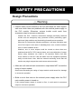
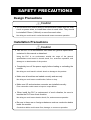
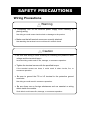
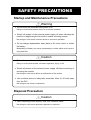


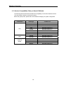
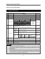

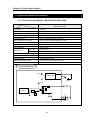


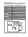
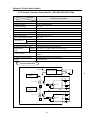
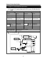
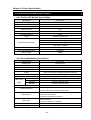
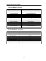
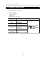
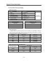

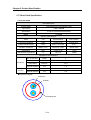


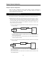
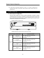

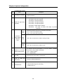
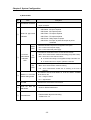
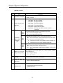
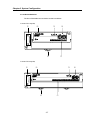
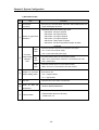

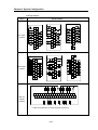
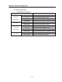
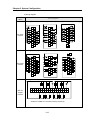


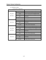
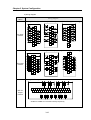

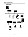
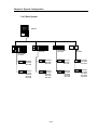
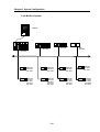
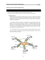
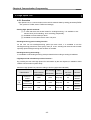
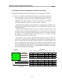
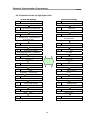
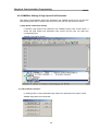
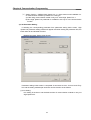


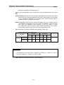

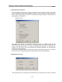

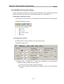
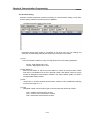
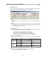

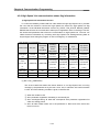
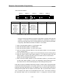
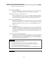

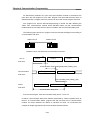

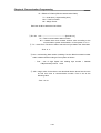


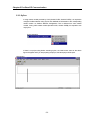

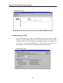
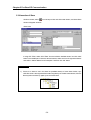
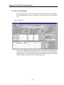
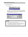
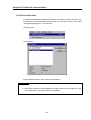
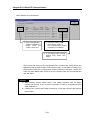

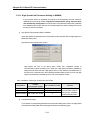
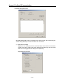
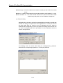
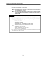


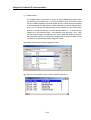
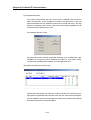
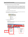


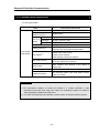
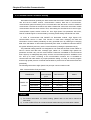
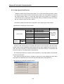
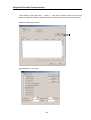


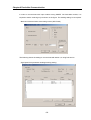
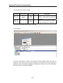

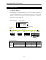
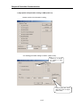
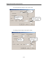
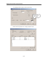
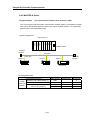


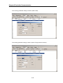
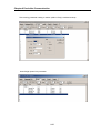
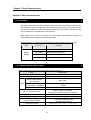
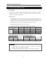
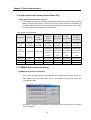
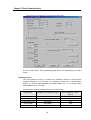


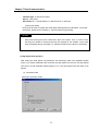
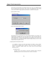
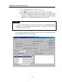

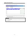
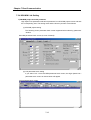
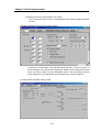
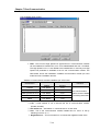
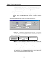
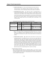

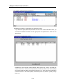
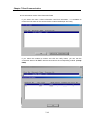
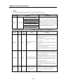


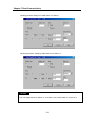

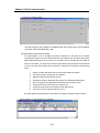
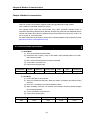
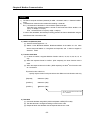
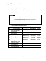
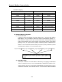
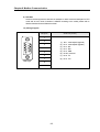
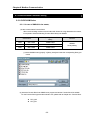
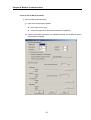

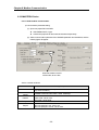
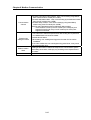
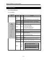
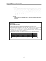
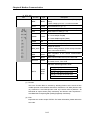
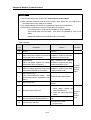

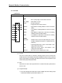
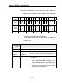
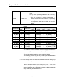

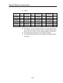

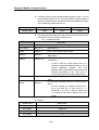
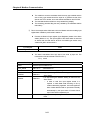
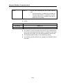
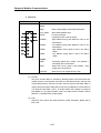
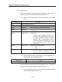
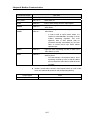


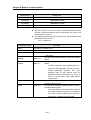
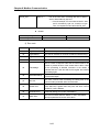
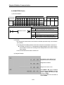

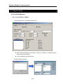
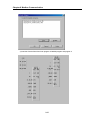
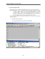
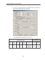
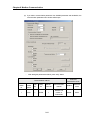

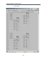
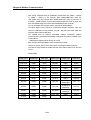
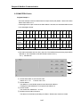
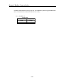
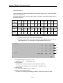

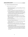
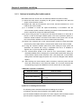


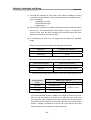
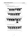
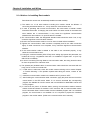
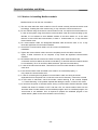
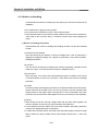


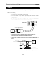
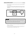
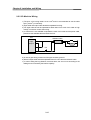

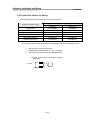
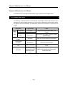
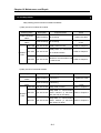
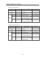
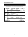
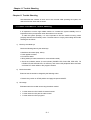
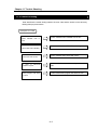
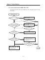
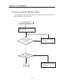
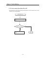
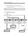
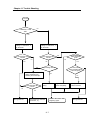

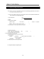


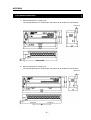
![[11] Chap.9 Installation and Wiring](http://vs1.manualzilla.com/store/data/005904878_1-e83dc78a4328ff11b1e565de6734c05d-150x150.png)