1
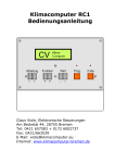
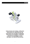
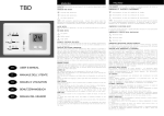
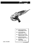
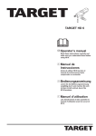
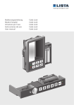
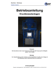
CL 74A 0-10V
Bedienung/Instruction
Stand: 11/01
Code Nr. 99 97 1503
M 1503 D/GB
Big Dutchman International GmbH; Auf der Lage 2, D-49377 Vechta
Tel.: 04447/ 801-0ŸFAX: 04447/ 801-237
CL 74A 0-10V
TABLE OF CONTENTS
GB
1. ENGLISH
1.1
1.2
1.3
1.4
1.5
1.6
1.7
1.8
1.9
INTRODUCTION .........................................................................................3
PRODUCT DESCRIPTION .........................................................................3
INSTALLATION ..........................................................................................3
OPERATION AND MAINTENANCE..................................................6
REPAIR SPARE PARTS ..................................................................8
ELETRICAL WIRING.......................................................................10
DISMOUNTING ................................................................................12
TROUBLE SHOOTING....................................................................12
MISCELLANEOUS ..........................................................................13
D
2. DEUTSCH
2.1
2.2
2.3
2.4
2.5
2.6
2.7
2.8
2.9
EINLEITUNG....................................................................................14
PRODUKTBESCHREIBUNG...........................................................14
MONTAGE UND INSTALLATION...................................................14
BEDIENUNG UND WARTUNG .......................................................17
REPARATUR UND ERSATZTEILE.................................................19
ELEKTRISCHE SCHALTPLÄNE.....................................................21
ABBAU.............................................................................................23
FEHLERSUCHE...............................................................................23
DIVERSES........................................................................................24
User Manual: Swivel Shutter
Edition: 11/01
M 1503 D/GB
2
CL 74A 0-10V
3
ENGLISH
1.1 INTRODUCTION
Important:
Before mounting and initial operation of your motor unit, please read
this instruction carefully.
1.2 PRODUCT DESCRIPTION
The CL 74A 0-10 V Swivel Shutter Motor Unit provides the continuously variable swivel
shutter control.
The CL 74A 0-10 V is mounted directly onto the swivel shutter shaft.
The CL 74A 0-10 V has manual emergency operation.
The CL 74 A 0-10 V is a motor unit designed to operate the swivel shutters in livestock and
to support the Big Dutchman CL 600 Chimney.
The CL 74 A 0-10 V can control also other Chimneys. With the Adapter Code Nr 60-47-8110
will the motor also control Reventa Chimneys 400/500/600/750/800/900mm.
1.3 INSTALLATION
Mounting of CL 74A 0-10 V on intake funnel:
If the CL 74A 0-10 V is supplied without being
mounted on the intake funnel of if it is supposed to be
mounted subsequently, please follow below direction:
Turn the damper to a closed position (Fig. 1)
Fig. 1
If you use CL 600 Chimneys:
Remove the adapter for Shaft 10-16 mm.
(Fig. 2)
Fig.2
User Manual: Swivel Shutter
Edition: 11/01
M 1503 D/GB
CL 74A 0-10V
4
The producer has prepared the Swivel Shutter Motor
Unit for mounting on a closed swivel damper
(end stop clockwise).
This is controlled by activating the trigger (fig. 3; pos. 3)
and turn the gear clockwise till it reaches the end stop.
It is now possible to mount the CL 74A 0-10V on the
intake funnel.
Fig. 3
Important:
The arm for the micro switch is to be
mounted by means of the 2 guide
spindles so that it is in a closed
position (fig. 3; pos. 1)
Activate the trigger (fig. 3; pos. 3) and turn the flap
counterclockwise to an open position (fig. 4) and
check that the flap can open completely.
Fig.4
Turn the flap back to the position closed and check
that the flap can close completely. (fig.3)
Fig. 5
User Manual: Swivel Shutter
Edition: 11/01
M 1503 D/GB
CL 74A 0-10V
5
The intake funnel is pushed vertically into place and
locked with the 4 screws and plates include.
(Fig.6 and 7)
A house will normally have 1 or more continuously
variable chimneys with a Emergency Opening
or without.
CL 74A 0-10 V has different ways of connections
to these 2 functions.
(see drawing No. 29-00001-00; Fig. 18a and 18b in
the rear of this instruction)
Fig. 6
Installation of cables:
CL 74A 0-10V is connected to the control unit or other
Swivel Shutter Motor Units
(see drawing No. 29-00001-00; Fig. 18a and 18b in
the rear of this instruction)
All cable are to be mounted PG16 threaded glands
with an enclosure to min. IP54.
Cable to be secured in the usual way outside the
cabinet. Holes not in use to be covered by IP54
safety plug.
Fig. 7
Mounting of Lid:
Mount the lid before initial start of the CL 74A 0-10 V
Swivel Shutter motor Unit.
Check the sealing and mount the lid.
Fasten the lid with the 5 screws.
Warning:
As the screws are tightened directly
into plastic it is important not to
tighten the screws to much.
Control of Trigger:
Fig. 8
After mounting of the lid, check the transmission trigger.
Press the membrane (fig. 8; pos.1) and check by
turning the swivel plate.
Mounting of CEE plug:
If you for reasons of security want the possibility
of switching off the current for the ventilator this can be
done by mounting a CEE plug in the lid. (fig.8)
Now the main current for the ventilator can be switched
off by dismounting the plug.
Fig. 9
User Manual: Swivel Shutter
Edition: 11/01
M 1503 D/GB
CL 74A 0-10V
6
1.4 OPERATION AND MAINTENANCE
Instruction:
CL 74A 0-10V is designed to operate without
supervision and is under normal conditions controlled
by the computer. Should it prove necessary the flap
can open manually by activating the manual switch
(fig. 10, pos.1). Should the situation arise where the
computer discontinues operation an optional
emergency control and a 24 V battery would secure
that all swivel shutters are opening automatically. This
will secure maximum ventilation if sufficient mains
voltage is available.
Fig. 10
Maintenance:
The CL 74A 0-10V does not require special
maintenance, but we recommend to have the system
serviced once a year.
The CL 74A 0-10V can be cleaned with conventional
cleaning materials and disinfectants. (fig. 11)
Fig. 11
When cleaning it is important not to damage the
sealings. (fig. 12)
Attention:
Pay special attention to the
cleaning of the shaft sealing
(fig. 12)
Fig. 12
User Manual: Swivel Shutter
Edition: 11/01
M 1503 D/GB
CL 74A 0-10V
7
Annual Check
1. Open the lid of the cabinet to check the inside functions.
Important:
it is important to check that the cabinet is tight as fluids will
damage gears and other components.
Pay attention to the shaft sealing and the sealing at the cables. If any sign of leakage is
observed, seal with silicone or replace the couplings.
2. Activate the manual release and check that the swivel shutter is moving freely in the
entire working area.
Replacing the Motor:
Warning !
Before removing the lid, switch off the power at the safety
switch.
♦ Turn the power and remove the lid.
♦ Disengage the plug and the strap that fastens the motor plug is loosed.
♦ Take out the motor and replace by a new motor. Fasten it with the strap and mount the
motor plug.
Attention:
Please observe that the plug must be placed
correctly.
♦ Mount the lid and connect the power.
User Manual: Swivel Shutter
Edition: 11/01
M 1503 D/GB
CL 74A 0-10V
8
1.5 REPAIR SPARE PARTS
Fig. 13
Fig. 14
Sparepart lists (pos.) Swivel Shutter Motor Unit CL 74A 10-10V
1
2
432052
3
432072
4
4
4
4
4
5
User Manual: Swivel Shutter
Edition: 11/01
M 1503 D/GB
Membrane for manual disconnecting.
Controllamp is on when power for operation is OK
and no thermos failure on the fan. (Optional extra).
Switch:
O = disconnected
I = connected (Controllamp on). (Optional extra).
Cable entry for potentiometer
Cable entry for 24V voltage in
Possible continuation of multiple cable to next Swivel
Shutter Motor Unit.
Cable entry from fan.
Mains supply in.
Possible continuation of mains supply to next Swivel
Shutter Motor Unit.
CL 74A 0-10V
9
on
c
d
12
11
Fig. 15
Microswitch d
Microswitch d
on
on
0°
on
on
90°
90°
0°
1
2
1
2
1
2
0....10VDC
0....20 mA
Fig. 16
User Manual: Swivel Shutter
Edition: 11/01
M 1503 D/GB
Fig. 17
1
2
2....20VDC
2....20 mA
CL 74A 0-10V
1.6 ELECTRICAL WIRING
Fig. 18a
User Manual: Swivel Shutter
Edition: 11/01
M 1503 D/GB
10
CL 74A 0-10V
Fig. 18b
User Manual: Swivel Shutter
Edition: 11/01
M 1503 D/GB
11
CL 74A 0-10V
12
1.7 DISMOUNTING
Warning:
Switch off power to CL 74A 0-10V
before dismounting.
Dismount the cables of CL 74A 0-10V and loosen the
screw in the centre, holding the “Arm for microswitch”.
(fig. 19, pos. 1)
Fig. 19
Lift the complete Swivel Shutter Motor Unit off
the shaft.
Disassemble the CL 74A 0-10V into the following elements:
Gearunit, Plasticbox and couplings, Metal frame and Electric components.
Deposit all parts at a recycling estate.
1.8 TROUBLE SHOOTING
Trouble Shooting/Repair
Although CL 74A 0-10V is designed to work without monitoring interruption of operation may
occur should this happen check and rectify according to the below list:
Swivel Shutter Motor Unit does not work:
F Check the supply voltage.
F Place the flap in central position, and it should now go back automatically.
If not:
F check control voltage.
If the control voltage is OK:
F replace the motor.
Fan does not work:
F Check supply and eventually control voltage 0-10V.
If they are OK:
F replace the fan.
User Manual: Swivel Shutter
Edition: 11/01
M 1503 D/GB
CL 74A 0-10V
13
1.9 MISCELLANEOUS
Service:
Service phone no.: +49 (4447) 801-0
After normal office hours an answering machine will inform you about the phone number of
the service personal in charge.
To get a useful answer, it is important that you give as much relevant information about your
problem as possible when using our service phone.
Further, it is recommended that you join your Big Dutchman dealer’s service arrangement.
Product Specification
TECHNICAL DATE:
Motor:
Back signal:
Control signals:
Control signals:
Running time (open/close):
max. drive torque:
Consumption:
-operation
-at end stops
Power:
Cabinet protection class:
direction of rotation /Factory setting:
User Manual: Swivel Shutter
Edition: 11/01
M 1503 D/GB
24 VDC
0-10 V R > 50k?
0-10 V Ri > 100k?
0-20 mA Ri 500k?
30 Sek.
8 Nm
4,0 Watt
0,6 Watt
7,5 VA
IP54
Clockwise rotation
CL 74A 0-10V
14
2. DEUTSCH
2.1 EINLEITUNG
Wichtig:
Bevor Sie Ihren neuen Stellmotor montieren und verwenden, bitte
folgendes Handbuch gründlich durchlesen.
2.2 PRODUKTBESCHREIBUNG
CL 74A 0-10V Stellmotor für stufenlose Regelung von Drehklappen.
Der CL 74A 0-10V wird direkt an der Stellachse montiert.
Der CL 74A 0-10V kann manuell notbedient werden.
Der CL 74A 0-10V Motor wurde speziell für die Montage im harten Stallmilieu und für die
Unterstützung der Big Dutchman-Klimacomputer entwickelt.
Der CL 74A 0-10V eignet sich auch für andere Kamine. Über einen Adapter (Code Nr.:
60-47-8110) bedient der Motor dann auch andere Drehklappen z.B. Kamine Reventa
400/500/600/750/800/900mm.
2.3 MONTAGE UND INSTALLATION
Montage von CL 74A 0-10V auf Einlaßrichter:
Falls der CL 74A 0-10V separat geliefert ist oder
nachträglich auf dem Einlaßrichter zu montieren ist,
muss es gemäß folgender Anweisungen gemacht
werden:
Die Klappe wird zur geschlossenen Position
Gedreht. (Abb. 1).
Abb. 1
Bei Verwendung von CL 600 Kaminen:
Entfernen Sie bitte den Adapter für Antriebswellen
von 10-16 mm. (Abb.2)
Abb. 2
User Manual: Swivel Shutter
Edition: 11/01
M 1503 D/GB
CL 74A 0-10V
15
Der Stellmotor ist von der Fabrik für die Montage auf
einer geschlossenen Drehklappe (Endstop im Uhrzeigersinn) vorbereitet.
Dies wird kontrolliert durch Betätigung des Auslösers,
(Abb. 3 Pos. 3) und Drehung des Getriebes im Uhrzeigersinn bis zum Anschlag.
Der CL 74 A 0-10V kann nun auf dem Einlaßtrichter
montiert werden.
Abb. 3
Wichtig:
Der Arm für den Microswitch muss
mittels der 2 Paßstifte so montiert
werden, daß er in geschlossener
Position steht. (Abb. 3; Pos. 1)
Der Auslöser (Abb. 3; Pos. 3) wird betätigt und die
Klappe gegen den Uhrzeigersinn bis zur offenen Position
gedreht (Abb. 4)
Abb. 4
Nun wird die Klappe wieder in die geschlossene
Position gedreht und es wird kontrolliert, ob die Klappe
im Kamin frei beweglich ist.
Abb. 5
Der Einlasstrichter wird senkrecht nach oben
geschoben und mit den mitgelieferten 4 Schrauben und
Scheiben befestigt (Abb. 6 und 7).
In einem Stall gibt es normalerweise einen oder
mehrere stufenlos gesteuerte Kamine mit oder ohne
Notöffnung.
Der elektrische Anschluß für diese beiden Funktionen
mit CL 74A 0-10V ist unterschiedlich.
User Manual: Swivel Shutter
Edition: 11/01
M 1503 D/GB
CL 74A 0-10V
16
(siehe Diagramm 29-0001-00; Abb. 18a und 18b
weiter hinten im Handbuch)
Abb. 6
User Manual: Swivel Shutter
Edition: 11/01
M 1503 D/GB
CL 74A 0-10V
17
Kabelmontage:
CL 74A 0-10V wird an die Steuerung oder an andere
Stellmotoren angeschlossen.
(siehe Diagramm 29-0001-001 Abb. 18a und 18b)
Alle Kabel werden mit PG16 Verschraubungen montiert
mit einer Schutzart von mindestens IP54.
Kabel werden normalerweise außerhalb des Gehäuses
entlastet.
Löcher, die nicht verwendet werden, mit IP54
Blindstecker schließen.
Abb. 7
Montage des Deckels:
Der Deckel wird montiert, bevor der CL 74A 0-10V
Stellmotor in Betrieb genommen wird.
Dichtung kontrollieren und Deckel montieren. Der
Deckel wir mit 5 Schrauben befestigt.
Achtung !
Da die Schrauben direkt in Plastik
geschraubt werden, ist es sehr
wichtig sie nicht zu fest anzuziehen.
Kontrolle des Auslösers:
Abb. 8
Wenn der Deckel montiert ist, den Schaltauslöser
kontrollieren.
Auf die Membran (Abb. 8, Pos. 1) drücken und durch
drehen der Klappenplatte kontrollieren.
Montage von CEE Stecker:
Falls es aus Sicherheitsgründen gewünscht ist, den
Strom für den Ventilator abzustellen, ist es möglich
einen CEE Stecker im Deckel zu montieren,
(Abb. 9).
Achtung:
Beim Demontieren des Steckers
muß der Hauptstrom für den
Ventilator abgeschaltet werden.
Abb. 9
User Manual: Swivel Shutter
Edition: 11/01
M 1503 D/GB
CL 74A 0-10V
18
2.4 BEDIENUNG UND WARTUNG
Anweisung:
CL 74A 0-10V wurde entwickelt für die Verwendung
ohne Aufsicht und wird normalerweise vom Stallcomputer gesteuert. Im Notfall läßt sich die Klappe
manuell öffnen durch Aktivierung der manuellen
Auslösung (Abb. 10, Pos. 2). Sollte der Computer
versagen, ist es möglich, durch eine Notsteuerung und
eine 24V Batterie im Computer (Option) zu sichern,
daß alle Klappen sich automatisch öffnen. Dadurch
wird, falls Netzspannung noch zur Verfügung steht, die
maximale Lüftung erreicht,.
Abb 10
Optionen:
•
•
Kontrollampe für Ventilator (Abb. 10, Pos. 2 )
Die Lampe leuchtet, wenn der Ventilator in Betrieb
ist.
Ventilatorschalter zum Ausschalten des Ventilators.
Wartung:
Der CL 74A 0-10V erfordert keine spezielle Wartung.
Es wird aber dennoch empfohlen, die Anlage einmal
pro Jahr überholen zu lassen.
Abb.11
Der CL 74A 0-10V kann mit herkömmlichen
Reinigungs- und Desinfektionsmitteln gereinigt werden.
(Abb. 11)
Abb 11
Bei der Reinigung ist es wichtig, daß die Dichtungen
nicht zerstört werden.
Achtung:
Die Wellendichtung besonders
vorsichtig säubern. (Abb 12)
Abb. 12
User Manual: Swivel Shutter
Edition: 11/01
M 1503 D/GB
CL 74A 0-10V
19
Jährlich durchzuführende Kontrollen:
1. Den Gehäusedeckel öffnen um die inneren Funktionen zu kontrollieren.
Achtung:
Es darf keine Flüssigkeit eindringen, da die Schaltung und andere
wichtige Komponenten dadurch zerstört werden.
Beachten Sie die Wellendichtungen und Kabeldurchführungen.
Bei geringster Undichtigkeit an den Kabeln, mit Silikon abdichten oder die Flanschen
ersetzen.
2. Den manuellen Auslöser aktivieren und kontrollieren, ob die Drehklappe sich im ganzen
Arbeitsraum frei bewegt.
Motorwechsel:
Warnung:
Bevor der Deckel entfernt wird, unbedingt den Strom am Sicherheitsausschalter ausschalten.
♦ Strom ausschalten und Deckel entfernen.
♦ Danach wird der Motorstecker abgezogen und der Bügel, der den Motor hält, wird
gelockert.
♦ Den Motor herausnehmen und den neuen Motor einlegen. Dieser wird mit dem Bügel
befestigt und der Motorstecker wird montiert.
Achtung:
Bitte beachten Sie, daß der Stecker korrekt sitzt
♦ Deckel montieren und Strom anschließen.
User Manual: Swivel Shutter
Edition: 11/01
M 1503 D/GB
CL 74A 0-10V
20
2.5 REPARATUR UND ERSATZTEILE
Abb. 13
Abb. 14
Ersatzteile Liste (s.) Stellmotor CL 74A 0-10V
1
2
432052
3
432072
4
4
4
5
Membran für manuelles Ausrücken
Kontrollampe leuchtet wenn Betriebsstrom vorhanden ist
und wenn kein Thermoausfall am Ventilator. (Option).
Schalter:
O = Ausgeschaltet
I = Eingeschaltet (Kontrollampe leuchtet). (Option).
Kabeleinführung für Potentiometer.
Kabeleinführung für 24V Spannung ein.
Eventuelle Weiterführung von Mehrleiterkabel zum
nächsten Motor.
Kabeleinführung vom Ventilator.
Eventuelle Weiterführung von Netzspannung zum
nächsten Motor für Drehklappe.
User Manual: Swivel Shutter
Edition: 11/01
M 1503 D/GB
CL 74A 0-10V
21
ON
C
d
1 2
Fig. 15
Mikroschalter d
0°
Mikroschalter d
on
90°
90°
on
on
on
0°
1
2
1
2
1
2
0....10VDC
0....20 mA
Fig. 16
User Manual: Swivel Shutter
Edition: 11/01
M 1503 D/GB
Fig.17
1
2
2....20VDC
2....20 mA
CL 74A 0-10V
2.6 ELEKTRISCHE SCHALTPLÄNE
Abb. 18a
User Manual: Swivel Shutter
Edition: 11/01
M 1503 D/GB
22
CL 74A 0-10V
Abb. 18b
User Manual: Swivel Shutter
Edition: 11/01
M 1503 D/GB
23
CL 74A 0-10V
24
2.7 ABBAU
Warnung:
Vor der Demontage den Strom für
CL 74A 0-10V ausschalten.
Die Kabel werden abgenommen und anschließend
werden die Schrauben, die den ” Arm für Mikroschalter“
halten, gelockert (Abb. 19, Pos. 1).
Abb. 19
Der komplette Stellmotor wird von der Achse gezogen.
CL 74A 0-10V wird danach in folgende Teile zerlegt:
Getriebeteil, Kunststoffkasten und Flanschen, Metallbodenplatten und EI-Komponenten.
Alle Teile werden an eine Wiederverwertungsstelle abgegeben.
2.8 FEHLERSUCHE
Fehlersuche und deren Beseitigung:
Obwohl der CL 74A 0-10V dafür entwickelt ist, ohne Überwachung zu arbeiten, können
Betriebsstörungen entstehen. In diesem Fall können Fehler nach folgender Liste überprüft
und beseitigt werden:
Der Stellmotor arbeitet nicht:
F 24V Spannung kontrollieren.
F Die Klappe in mittlere Position bringen: Sie sollte nun selbsttätig zurückgehen.
Falls nicht:
F die Steuerungsspannung kontrollieren.
Ist diese in Ordnung:
F den Motor austauschen.
Ventilator arbeitet nicht:
F Netzspannung und eventuell Steuerspannung zu den Kontakten kontrollieren.
Sind diese in Ordnung:
F den Ventilator austauschen
User Manual: Swivel Shutter
Edition: 11/01
M 1503 D/GB
CL 74A 0-10V
25
2.9 DIVERSES
Kundendienst:
Kundendienst Telefonnummer:+49 (4447) 801-0
Nach Geschäftsschluß wird ein Anrufbeantworter die Nummer für den diensthabenden
Kundendienstmitarbeiter mitteilen.
Um gute Beratung zu bekommen ist es wichtig, dass Sie unserem Kundendiensttelefon so
viele relevante Auskünfte wie möglich über Ihr Problem geben können.
Wir empfehlen außerdem, dass Sie im Kundendienstfall Ihren Händler kontaktieren.
Produktspezifikation:
TECHNISCHE DATEN:
Motor:
Rückmeldesignal:
Steuersignal:
Steuersignal:
Laufzeit (Auf/Zu):
Max. Drehmoment:
Leistungsaufnahme:
in Betrieb
in Endstellung
Leistung:
Gehäuse Schutzart:
Drehrichtung (Werkseinstellung):
User Manual: Swivel Shutter
Edition: 11/01
M 1503 D/GB
24 VDC
0-10 V R > 50k?
0-10 V Ri > 100k?
0-20 mA Ri 500k?
30 Sek.
8 Nm
4,0 Watt
0,6 Watt
7,5 VA
IP54
im Uhrzeigersinn