1
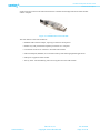
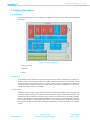
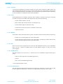
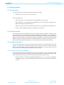
Novelda Development Kit User Guide
www.novelda.no
Rev. No: 3.0.5
Copyright © 2012 Novelda AS
30-Jul-2012
Page 1 of 35
Novelda Development Kit User Guide
Table of Contents
1. About this user manual ................................................................................................. 3
2. Abbreviations ............................................................................................................. 4
3. Development Kit Architecture ........................................................................................ 5
4. Hardware Description ................................................................................................... 6
5. Software Description .................................................................................................. 11
6. Getting started ........................................................................................................... 13
7. Development ............................................................................................................. 30
8. Troubleshooting ........................................................................................................ 31
9. Contact Information ................................................................................................... 34
10. Disclaimer .............................................................................................................. 35
www.novelda.no
Rev. No: 3.0.5
Copyright © 2012 Novelda AS
30-Jul-2012
Page 2 of 35
Novelda Development Kit User Guide
1. About this user manual
1. About this user manual
The user manual for the Novelda NVA-R6X1 development kit contains the information needed for
anyone who would like to get to know the Novelda Impulse Radar technology or to start developing
applications based on the NVA6X00 Impulse Radar chip. The user guide contains the following chapters:
• Chapter 3, Development Kit Architecture, provides an architectural overview of the Development
Kit contents.
• Chapter 4, Hardware Description, describes the Development Kit hardware in greater detail.
• Chapter 5, Software Description, describes the Development Kit software architecture and how
the different modules are organized.
• Chapter 6, Getting Started, describes the necessary steps to get the kit up and running, including
instruction for assembling the different parts.
• Chapter 7, Development, recommendations for setting up a standard development environment
• Chapter 8, Troubleshooting, A troubleshooting guide for the most common problems
1.1. Additional information
Additional information and support material is always available on our website: http://www.novelda.no.
This includes a up to date version of this document, latest news and frequently asked questions. In addition, readers are encouraged to read and become familiar with the NVA6X00 Datasheet and the
Novelda Nanoscale Impulse Radar white paper. Depending on the development kit you are using, the
following chip datasheet apply:
Development kit
Chip Datasheet
NVA-R621
NVA6000-PQ32
NVA-R631
NVA6100-PQ32
NVA-R641
NVA6100-PQ32
Table 1.1. Chip datasheet overview
Throughout this document the development kit is referred to as NVA-R6x0 and chip as NVA6x00.
When installing the software bundle, there will under Windows be added a separate folder for documentation. The folder will include the following:
• Quick start guide
• This user guide
• API documentation
• Software License Agreement
www.novelda.no
Rev. No: 3.0.5
Copyright © 2012 Novelda AS
30-Jul-2012
Page 3 of 35
Novelda Development Kit User Guide
2. Abbreviations
2. Abbreviations
Abbreviations
Description
API
Application Programming Interface
CMOS
Complementary metal-oxide-semiconductor
CPU
Central Processing Unit
FTDI
Future Technology Devices International Ltd
GUI
Graphical User Interface
I/O
Input/Output
LED
Light Emitting Diode
PPTC
Polymeric Positive Temperature Coefficient
RF
Radio Frequency
RX
Receiver
SMA
Sub Miniature version A
SPI
Serial Peripheral Interface
TX
Transmitter
USB
Universal Serial Bus
Table 2.1. Abbreviations.
www.novelda.no
Rev. No: 3.0.5
Copyright © 2012 Novelda AS
30-Jul-2012
Page 4 of 35
Novelda Development Kit User Guide
3. Development Kit Architecture
3. Development Kit Architecture
The Novelda NVA-R6x1 development kit is built up of both hardware and software modules in a
layered architecture. The hardware consists of a set of two antennas, a radar-module and an I/O-module.
The first software layer consists of a driver and a library for the I/O-module. This layer is specific to
the I/O-module and is provided by the I/O-module manufacturer. The middle software layer is called
Radarlib3 and handles the communication between the I/O-module and the user application. On top of
Radarlib3 the user application will receive, process and present the data from the radar-module.
Figure 3.1. Development kit architecture
www.novelda.no
Rev. No: 3.0.5
Copyright © 2012 Novelda AS
30-Jul-2012
Page 5 of 35
Novelda Development Kit User Guide
4. Hardware Description
4. Hardware Description
4.1. Overview
The purpose of the Novelda NVA-R6x1 development kit is to help the user get started within a short
amount of time. The kit therefore includes everything that is needed to get up and running and should
function as a starting point for both getting to know the technology and for development of user applications. The hardware part of the Novelda NVA-R6X1 development kit consists of three main parts as
illustrated in the figure.
Figure 4.1. Hardware architecture
• I/O-module (USB to SPI adapter)
• Reference RF design with the NVA6x00 Impulse Radar chip
• A set of two Sinuous or Vivaldi antennas
4.1.1. Antennas
The NVA-R6X1 Novelda Development kit is delivered with a set of two antennas, one for TX and one
for RX. Each kit can be delivered with one or more of the following antenna options, depending on
regulatory and size requirements:
D e v e l o p - Antenna Size
ment kit
type
Bandwidth
Beamwidth
Compliance
NVA-R621
Sinuous
45mm x 45mm x 10mm 6GHz to 8.5GHZ
without lens (45mm
with lens)
40° with lens, ETSI/FCC
80° without lens
NVA-R631
Vivaldi
150mm x 133mm
20° E-plane, 50°
H-plane
NVA-R641
Sinuous
50mm x 50mm x 17mm 3.0GHz to 6.0GHZ 40° with lens, ETSI/FCC
without lens (50mm
80° without lens
with lens)
Vivaldi
150mm x 133mm
0.9GHz to 5GHZ
0.9GHz to 5GHZ
20° E-plane, 50°
H-plane
Table 4.1. Antennas features
www.novelda.no
Rev. No: 3.0.5
Copyright © 2012 Novelda AS
30-Jul-2012
Page 6 of 35
Novelda Development Kit User Guide
4. Hardware Description
4.1.2. Radar-module
The radar-module is where the NVA6x00 radar chip is located. For more information on the radarmodule, please refer to the corresponding radar-module datasheet.
Figure 4.2. Radar-module top view
4.1.2.1. Features
The main features of the radar module board are:
• Small form factor for easy implementation
• Digital SPI port for low threshold development on other digital platforms
• Cost efficient design for price sensitive applications
• Optimized RF performance through grounded coplanar waveguide design
• RF match compatibility option through resistive matching possibility on RX and TX
• On-board 100MHz CXO option for high speed and performance
• Module power down function for low power duty cycled measurements
• On-board FLASH for storing individual calibration or other data
• OTP ID programming option
• Improved power distribution for high performance
• Standardized SMA connectors
4.1.2.2. I/O header
On the radar module there is a 20-pin connector that the I/O module uses to communicate with the
NVA6X00 chip. The table below shows how each of the pins is connected.
www.novelda.no
Rev. No: 3.0.5
Copyright © 2012 Novelda AS
30-Jul-2012
Page 7 of 35
Novelda Development Kit User Guide
4. Hardware Description
I/O header on the radar module
Usage
Pin num- Usage
ber
GND
1
2
MCLK_EXT
GND
3
4
SCLK
GND
5
6
MOSI
GND
7
8
MISO
GND
9
10
nSS
GND
11
12
MCLK_SEL
GND
13
14
PWRENABLE
GND
15
16
nSS-ID
GND
17
18
VDD
GND
19
20
GND
Table 4.2. I/O header on the radar module
It is only the power supply for the radar module that should be supplied with 5V. All the IO-pins for
the radar module are 3.3V.
MCLK_EXT
This pin allows an external clock source to be used as a trigger instead of the clock generator on the
I/O module. This option gives the following advantages:
• The option of selecting a clock frequency that better fits the application..
• Using the same clock signal for more than one radar.
SCLK (SPI clock)
SPI Clock input pin. This pin is connected directly to the SCLK pin (pin 20) on NVA6X00. Electrical
characteristics and operating conditions can be found in the NVA6X00 data sheet.
MOSI (SPI)
SPI Master Out Slave In input pin. This pin is connected directly to the MOSI pin (pin 19) on NVA6X00.
Electrical characteristics and operating conditions can be found in the NVA6X00 data sheet.
MISO (SPI)
SPI Master In Slave Out output pin. This pin is connected to the MISO pin (pin 18) on NVA6X00
through a 2.5 to 3.3 V level shifter.
nSS (SPI slave select for radar chip)
SPI Slave Select (active low) input pin for the radar chip. This pin is connected directly to the nSS pin
(pin 21) on NVA6X00. Electrical characteristics and operating conditions can be found in the NVA6X00
data sheet.
MCLK_SEL
This pin is used to switch between the internal clock and the possibility of using an external clock
through MCLK_EXT.
• MCLK_SEL high -> external oscillator
www.novelda.no
Rev. No: 3.0.5
Copyright © 2012 Novelda AS
30-Jul-2012
Page 8 of 35
Novelda Development Kit User Guide
4. Hardware Description
• MCLK_SEL low -> onboard oscillator
PWRENABLE
This pin is used for powering down the power regulator on the radar module.
• PWRENABLE high -> radar module powered on
• PWRENABLE low -> radar module powered down
The pin is connected directly to MCLK pin (pin 22) on the NVA6X00 chip. For electrical characteristics
and operating conditions, please refer to the NVA6X00 data sheet.
nSS-ID (SPI slave select for Flash memory)
SPI Slave Select (active low) input pin for the Flash memory. This pin is used to activate Flash for
storing and retrieving variable values and reading the serial number of the development kit.
VDD 5V power supply
The pin supplies the radar-module with 5V power.
GND power supply
The pin supplying the radar-module with ground power.
4.1.2.3. Chip info
The NVA6X00 chip is mounted on the radar-module. There are currently six different development
kits available, which are using two kinds of radar chips.
Development kit
Chip
NVA-R621
NVA6000
NVA-R631
NVA6100
NVA-R641
NVA6100
Table 4.3. Development kits and chips used
For more information about the NVA6X00 chips, please refer to the NVA6X00 datasheet that can be
downloaded from the Novelda web site.
Some of the common features for the radar chips are:
• Single chip CMOS Impulse RADAR
• Close Range Operation
• High-resolution
• Simultaneous observation of 512 depths
• High speed; > 30GS/s Sampling rate
• Ultra low RF emission (less than FCC Part 15 limit)
4.1.3. I/O module
The I/O module used in the Novelda development kit is manufactured by Future Technology Devices
International Ltd (FTDI) and is called C232HM. The I/O module is a USB to SPI adapter which has
www.novelda.no
Rev. No: 3.0.5
Copyright © 2012 Novelda AS
30-Jul-2012
Page 9 of 35
Novelda Development Kit User Guide
4. Hardware Description
all the electronics built into the cable itself and is the communication bridge between the radar-module
and the computer.
Figure 4.3. C232HM USB to SPI I/O module
The main features of the I/O-module are:
• Standard USB to SPI IO adapter, requiring no firmware development
• Enables easy and powerful development possibilities on a computer
• Customized connector for interface to Novelda radar modules
• USB 2.0 Hi-Speed (480Mb/s) for increased transfer speeds enabling high FPS applications
• USB power supplied to radar module
• Activity LED - red LED flashing when retrieving data from the radar-module
www.novelda.no
Rev. No: 3.0.5
Copyright © 2012 Novelda AS
30-Jul-2012
Page 10 of 35
Novelda Development Kit User Guide
5. Software Description
5. Software Description
5.1. Overview
The software part of the Novelda NVA-R6X1 development kit consists of three main parts as illustrated
in the figure.
Figure 5.1. Software architecture
• User applications
• Radarlib3
• Drivers
5.1.1. Drivers
At the bottom of the software stack for the development kit, the drivers and libraries are located. It is
the driver for the I/O-module that makes the module visible and accessible for the operating system
om the computer. On top of the driver there is a library that functions as an API to the I/O module. It
is towards this API a Radarlib3 interface is made, making it possible for Radarlib3 to communicate
with the I/O-module and the radar-module.
5.1.2. Radarlib3
Radarlib3 is the part of the software architecture that ties together all the different parts of the software
architecture. When initiating, this module requests information from the attached I/O-modules. The
information is used to compose a connection string, which in turn loads all the correct software modules.
Based on the information from the different modules, the correct drivers and libraries are loaded, the
I/O and radar module are enabled and loaded with the correct default values. The Radarlib3 module
then exposes one API that will remain unchanged independently of what kind of radar or I/O module
is used.
www.novelda.no
Rev. No: 3.0.5
Copyright © 2012 Novelda AS
30-Jul-2012
Page 11 of 35
Novelda Development Kit User Guide
5. Software Description
5.1.2.1. Interface
At the bottom of Radarlib3 the interface modules are located. These modules are different from each
other and developed especially for each type of I/O-module that is to be connected to the software stack
of the Novelda development kit. The module converts the API that is exposed from the driver and library
of the I/O-module to a standard that can be used by Radarlib3.
5.1.2.2. Chip
Inside Radarlib3 there are modules called chip. These modules are specific for each type of chip that
Novelda can supply for the different development kits and contains the following:
• All the variables related to the chip
• Meta variables and variables related to controlling the chip
• All the available registers related to the chip
• All the functions that can be used in combination with the chip
• Calibration routines
5.1.2.3. Module
This module contains information that is specific to the radar-module used and contains the following:
• Variables for controlling digital I/O on the radar-module
• All the information about the Flash on the radar-module, including the variables and functions
used to read and program the Flash on the radar module
5.1.2.4. API
There are several ways an application can access the API of Radarlib3. Directly on top of Radarlib3
there is an C/C++ interface. In addition there are several different wrappers, for easy access using
other languages.
5.1.2.5. API Wrappers
The API wrappers are on top of the C/C++ API for easy access to Radarlib3 using the following languages:
• .NET (for .NET applications and Matlab applications)
• Python*
• Java* (for Java and Matlab applications)
* to be implemented later in 2012
5.1.3. User applications
The user applications that are developed will be located on top of the API. It is also on this level that
the demo application RadarScope is located, accessing Radarlib3 through the .NET wrapper.
www.novelda.no
Rev. No: 3.0.5
Copyright © 2012 Novelda AS
30-Jul-2012
Page 12 of 35
Novelda Development Kit User Guide
6. Getting started
6. Getting started
6.1. Requirements
The development kit is intended for the following operating systems:
• Windows (XP, Vista and 7) 32 or 64 bit versions
Other requirements are:
• .NET framework 4.0 or later (RadarScope and the Radarlib3 .NET wrapper)
• .NET compatible version of MATLAB ( R2010b SP2 or later) is required to load and use the
MATLAB examples with Radarlib3.NET.
• A dual core CPU and at least 2 GB RAM (1 GB for XP) is recommended to run RadarScope.
• At least one free USB port where the I/O-module can be attached.
6.2. Software Bundle
The software bundle for the development kit consists of all the software needed for customers to start
the development as well as the ready to run application RadarScope. RadarScope is a .NET application
and can demonstrate much of the radar functionality and illustrate how the radar can be configured. In
addition the software bundle also includes the complete documentation for the development kit and its
different modules. The software bundle can be downloaded from the Novelda web site (http://www.novelda.no/content/development-kit-resources) once the customer has a user name and password.
6.3. Software Installation
The software bundle comes in both a 32- and 64-bit version. Make sure to install the right version from
the start, since the libraries are different and must match the version of other tools like for instance
Matlab. After downloading the software bundle from the Novelda web site, please follow these step
by step instructions to ensure that the installation is done correctly.
6.3.1. Installation procedures for Windows
The documentation and all the files needed for the software installation comes packed in one single
executable package. Execute the installation package and the installer will guide you through the different steps. Please follow these steps to ensure that the installation is done correctly.
• Start the installer by executing the RadarSoftwareBundle_setup_x.x.x.x_x64.exe or RadarSoftwareBundle_setup_x.x.x.x_x86.exe file depending on what version of the software and libraries
to install.
www.novelda.no
Rev. No: 3.0.5
Copyright © 2012 Novelda AS
30-Jul-2012
Page 13 of 35
Novelda Development Kit User Guide
6. Getting started
Figure 6.1. Executing the RadarSoftwareBundle_setup_x.x.x.x_x64.exe file
• Click Next
Figure 6.2. Software license agreement
• Accept the software license agreement and click Next
Figure 6.3. Select the location of where to install the software bundle
www.novelda.no
Rev. No: 3.0.5
Copyright © 2012 Novelda AS
30-Jul-2012
Page 14 of 35
Novelda Development Kit User Guide
6. Getting started
• Select the folder the installer should use for the software bundle and click Next
Figure 6.4. Select components to install
• Select Full Installation and click Next
Figure 6.5. Select Start Menu folder
• Select a Start menu folder name and click Next
www.novelda.no
Rev. No: 3.0.5
Copyright © 2012 Novelda AS
30-Jul-2012
Page 15 of 35
Novelda Development Kit User Guide
6. Getting started
Figure 6.6. Create a desktop icon
• Click Next
Figure 6.7. Ready to install
• Click Install to start the installation
Figure 6.8. Installing the software bundle
www.novelda.no
Rev. No: 3.0.5
Copyright © 2012 Novelda AS
30-Jul-2012
Page 16 of 35
Novelda Development Kit User Guide
6. Getting started
• When the installation has completed, click Finish to exit the installer. If the hooks are left on,
the installer will automatically open the documentation and launch the RadarScope application.
Figure 6.9. Installation completed
6.4. Drivers
The drivers needed for the computer to connect correctly to the I/O module can be downloaded from
the FTDI web site (http://www.ftdichip.com/Drivers/D2XX.htm). Select the driver that matches the
operating system on the computer.
6.4.1. Windows
For Windows there are two ways of installing the drivers. Either by downloading the drivers and installing them manually or by letting Windows automatically install the drivers. The automatic installation
will start the first time the hardware is connected if no drivers previously have been installed. When
plugging the I/O module into the computer, Windows will automatically start to search and download
the correct drivers. If there is a problem or the development kit should be installed on a computer
without a network connection, the drivers can be downloaded manually. Go to the FTDI web site and
click on the link for the Windows drivers to start the download. All the needed drivers are packed together into a compressed file of type .zip. The Microsoft operating systems (Windows 7, Vista and XP)
will open the zip-file directly. The driver package does not include any installer and the drivers must
be updated from Device Manager after the I/O-module has been attached.
6.5. Assembling the hardware
The NVA-R6X1 development kit requires a minimum of hardware assembling. A new kit only needs
to get the antennas and the I/O module connected to be operational. Figure 6.9 shows a picture of an
assembled kit.
www.novelda.no
Rev. No: 3.0.5
Copyright © 2012 Novelda AS
30-Jul-2012
Page 17 of 35
Novelda Development Kit User Guide
6. Getting started
Figure 6.10. Assembled kit, complete with antennas and I/O-module
6.5.1. Connecting the antennas
The connecting of the antennas should be the same either if the supplied antenna type is Sinuous or
Vivaldi. Included in the kit are two antennas, one for TX and one for RX. Both antennas have a 50
Ohm SMA connector. Connect the antennas to the RX and TX ports on the radar module using the
SMA connectors.
6.5.2. Connecting the I/O module
The I/O-module and the radar module is connected through a 20-pin connector. There should be a mark
on the connector indicating the correct way of inserting the connector. Once located, connect the connector on the I/O-module into the connector on the radar module.
6.6. Connecting the hardware
Once the software bundle and the drivers are installed correctly, the hardware can be connected to the
computer. Select a free USB port and plug in the cable for the I/O-interface.
6.7. RadarScope
RadarScope is a .NET demo application and is installed together with the software bundle.
6.7.1. Start Up
Make sure that the development kit is properly connected to the computer before starting RadarScope.
Once connected, RadarScope can be started from Start menu → Programs → Novelda → RadarScope.
www.novelda.no
Rev. No: 3.0.5
Copyright © 2012 Novelda AS
30-Jul-2012
Page 18 of 35
Novelda Development Kit User Guide
6. Getting started
Figure 6.11. RadarScope with connected kit
Once RadarScope has loaded and detected a connected kit, it will be indicated by a connection string.
If the connection string text box reads "No Radar found", try clicking the refresh button. If no connection
string appears, please check that the kit is still connected to the computer.
The connection string will typically look like this: FTx232H!Serial No: (FTUP3KET)!NVAR610A!NVA6100. The table bellow shows how the connection string is built up.
Module name Serial number Name
develop- Version number
(software)
(interface)
ment kit
of radar chip
FTx232H
FTUP3KET
NVA-R641
NVA6100
Table 6.1. Buildup of connection string
It is this connection string that RadarScope uses to connect to the right kit. Because RadarScope uses
the connection string instead of a physical or virtual COM port to connect to the kit, the kit can actually
be moved from one USB-port to another without having to change the connection string. As long as
the kit is connected to a USB-port, the Novelda software will connect to the right kit. This is especially
helpful when working with several kits that are connected to the same computer.
6.7.2. Connecting to the radar
Once the development kit is connected and RadarScope started, there should be a connection string
listed for each development kit connected to the computer. To ensure that the connection strings are
correct and up to date, click the Refresh-button.
www.novelda.no
Rev. No: 3.0.5
Copyright © 2012 Novelda AS
30-Jul-2012
Page 19 of 35
Novelda Development Kit User Guide
6. Getting started
Figure 6.12. Connecting radar in RadarScope
Select the connection string for the development kit to connect to and press Connect. The different
RadarScope windows will appear after the connection with the development kit has been successfully
established.
Figure 6.13. RadarScope with connected radar
6.7.3. Starting and stopping the radar
Frame capturing is started by pressing the Start Radar button in RadarScope.
www.novelda.no
Rev. No: 3.0.5
Copyright © 2012 Novelda AS
30-Jul-2012
Page 20 of 35
Novelda Development Kit User Guide
6. Getting started
Figure 6.14. Start frame capture by pressing the Start Radar button
Once the radar has been started, all the windows will start to update with the data captured by the radar.
Figure 6.15. Radar started
When capturing is running, it can be stopped by pressing Stop radar.
www.novelda.no
Rev. No: 3.0.5
Copyright © 2012 Novelda AS
30-Jul-2012
Page 21 of 35
Novelda Development Kit User Guide
6. Getting started
6.7.4. Description of different windows in RadarScope
6.7.4.1. Interactive RadarView
The Interactive RadarView window communicates directly with the development kit and features interactive adjustment of variables through intuitive click and drag mouse operations. From the Interactive
Radar View window there are several operations that can be done.
Manually Updating Variables
The development kit is controlled through a set of variables. All variables are available in the list on
the left hand side of the window. Only the most frequently used variables are shown by default, the
rest of the variables are shown by selecting View → View all variables.
Figure 6.16. Interactive Radar View
To change the value of a variable, select it from the list and enter the new value into the text box or
select it from the drop down menu and press Set. The variable can be reset to its default value by
pressing the reset button.
Vertical Zoom Mouse Gesture
Initially the windows in the application show the whole range. Depending on the sampled signal, the
amplitude might not be so noticeable. The mouse can be used to increase the vertical zoom (affecting
the ZoomMin and ZoomMax variables). Press and hold down the left mouse button and drag the mouse
pointer to the next position. A horizontal yellow marker will appear at the first point of the operation.
Release the mouse button and the window will update itself with the new settings.
Figure 6.17. Vertical zoom with the mouse
Context Menu
The context menu is accessed by right clicking anywhere in the Interactive Radar View window (except
inside the text boxes). Use the Zoom Out and Zoom Full buttons from the context menu to decrease
the vertical zoom.
www.novelda.no
Rev. No: 3.0.5
Copyright © 2012 Novelda AS
30-Jul-2012
Page 22 of 35
Novelda Development Kit User Guide
6. Getting started
Figure 6.18. Dumping capture frames to file
To dump captured frames to a file, access the context menu and select Dump to file → Choose file...
Now select Dump to file → Enable to begin dumping data.
The first column of each line contains a time stamp. The data is stored as comma separated values in
a .csv-file and can easily be imported in other tools such as Excel and Matlab.
Figure 6.19. Accessing the QuickMeas feature
The QuickMeas feature is used to display information about the capture frame. QuickMeas will also
place markers at the min/max position in the display frame (yellow arrows). The feature is accessed
by selecting QuickMeas in the context menu.
Keyboard Shortcuts
Use the right and left arrow keys to adjust the FrameOffset one bin at the time or use the up and down
arrow keys to adjust the vertical zoom.
World View
The World View shows the position of the captured radar frame relative to the world. It also shows the
estimated distance between the antenna and the radar frame based on the FrameOffset in bins (1 bin is
the equivalent to 1 MediumTune element) and mm. Press and hold the left mouse button over the frame
and drag it horizontally to adjust the FrameOffest.
Figure 6.20. World View
6.7.4.2. Filtered View
Filtered View displays the change in the frame over time before adding the filter.
www.novelda.no
Rev. No: 3.0.5
Copyright © 2012 Novelda AS
30-Jul-2012
Page 23 of 35
Novelda Development Kit User Guide
6. Getting started
Figure 6.21. Filtered View
Filters can be enabled/disabled via the context menu (right click within the plotting window). The
Filtered View window includes vertical zoom features similar to the Interactive Radar View window.
Zooming in the Filteres View window does however not affect the ZoomMin and ZoomMax variables.
6.7.4.3. Selected Sampler View
Selected Sampler View displays one or more selected sampler's values over time.
Figure 6.22. Selected Sampler View
Selecting samplers is done via the context menu (right click within the plotting window). More than
one sampler can be selected by holding down the Ctrl-key while selecting sampler numbers.
6.7.4.4. Graymap View
Graymap view displays a 2-dimensional gray-tone plot of frames over time.
www.novelda.no
Rev. No: 3.0.5
Copyright © 2012 Novelda AS
30-Jul-2012
Page 24 of 35
Novelda Development Kit User Guide
6. Getting started
Figure 6.23. RadarScope Graymap View
Graymap view can use both Interactive Radar View and Filtered View as source, selectable via the
context menu (right click within the plotting window). The default source is Filtered View.
6.7.5. Calibration Tool
RadarScope includes a "Calibration Tool" to help with calibration of some variables. Calibration is
implemented as a set of "Actions" and "Variables". Calibration Tool is started from the Tools → Calibration Tool menu. The calibration tool form has a button "Run Calibration" that triggers execution
of the calibration actions, and the list below displays the variables set during calibration. The lower
part of the form displays additional calibration data for the last calibration run.
Figure 6.24. RadarScope calibration tool
6.7.6. Settings
Variable settings, options and some other settings used to configure RadarScope and the radar module
can be saved to and restored from file.
www.novelda.no
Rev. No: 3.0.5
Copyright © 2012 Novelda AS
30-Jul-2012
Page 25 of 35
Novelda Development Kit User Guide
6. Getting started
Figure 6.25. Saving and loading settings
Files with default settings are provided with the installation program and can be found in a subdirectory
under the RadarScope installation: <Installation path>\RadarScope\Ini files\.
You can also set some options as default when RadarScope starts. These options include: Windows
sizes, Capture mode (Pipelining). Use "Save Options as default setup" in the File menu.
6.7.7. RadarScope Options
Under the File menu on top of RadarScope, it is possible to select Options.
Figure 6.26. RadarScope Options
From this menu there are several options available related to configuring RadarScope and how variable
values are stored and retrieved.
Auto save / restore of variable values to Flash on Radar Module
Under saving and restoring variable values to Flash there are two possible options that can be checked
off. When checking off the option for "Save variables values when connection to Radar Module is
closed", the variable values will automatically be stored to the Flash memory on the radar module either
when the disconnect button in RadarScope is pushed or when RadarScope is shut down. This will ensure
that the variable values that were currently used, will be saved and can be retrieved either on the same
computer or if the radar module were to be connected to a different computer.
www.novelda.no
Rev. No: 3.0.5
Copyright © 2012 Novelda AS
30-Jul-2012
Page 26 of 35
Novelda Development Kit User Guide
6. Getting started
The second option called "Restore saved variable values when connection to Radar Module is opened"
will when hooked off automatically retrieve the values from the Flash memory in the radar module. If
this option is activated before a complete set of variable values have been saved to the Flash memory
on the radar module, an error message will be displayed.
Figure 6.27. Auto restore of variables failed
This error message might also appear the first time RadarScope is started after a software update if the
number of variables or the variable structure has changed in between. The error message will disappear
the first time a valid set of variable values are stored to the Flash in the radar module.
Miscellaneous options
Under Miscellaneous options there are two different alternatives that are related to each other. The first
option which is experimental enables the support for two radars. When this option is not enabled, it is
still possible to have several radars connected to the pc, but RadarScope will only connect to one radar
at the same time.
Figure 6.28. Support for two radars not enabled
By enabling the experimental options for two radar support in RadarScope, the top of RadarScope will
be expanded if more than one supported radar module is connected to the computer.
Figure 6.29. Support for two radars enabled
Each of the two radars is labeled individually with Radar 1 and Radar 2. Once both radar modules are
connected, the status line at the bottom of the RadarScope windows will contain status information
about both radars and in the Interactive Radar View, the variable values for both radar modules can be
set.
www.novelda.no
Rev. No: 3.0.5
Copyright © 2012 Novelda AS
30-Jul-2012
Page 27 of 35
Novelda Development Kit User Guide
6. Getting started
Figure 6.30. RadarScope with two radars connected
When both radar modules are connected, the variable values are set by first selecting the radar module.
Once selected, the variable is selected and a value set by typing the value into the variable value field
and pushing the "Set" button. There is also a button labeled "Reset All" that will restore all the variable
values of the radar module back to its recommended settings.
Figure 6.31. Setting variables with two radars connected
With two radar modules running at the same time, colors are used to part them from each other. Radar
1 has the green color like before when being displayed in Interactive Radar View, Filtered View and
Gray Map. When radar 2 starts up, the two radars are differentiated by using different colors in the
three windows where they are plotted.
www.novelda.no
Rev. No: 3.0.5
Copyright © 2012 Novelda AS
30-Jul-2012
Page 28 of 35
Novelda Development Kit User Guide
6. Getting started
Figure 6.32. Interactive RadarView with two radars running
The last option under Miscellaneous is "Synchronize captures when two radars are connected". This
option only has effect when the data from the Interactive Radar View window are logged to file. The
Synchronize option then makes sure that the data logged in the log file are synchronized so that data
from the two radar modules are stored correctly in relation to each other.
Application settings
The last option is the one labeled "Save application settings when application closes". Enabling this
option will make RadarScope save the different application settings (like windows size and placement)
which are in effect at the moment the application closes.
www.novelda.no
Rev. No: 3.0.5
Copyright © 2012 Novelda AS
30-Jul-2012
Page 29 of 35
Novelda Development Kit User Guide
7. Development
7. Development
The user manual for the Novelda NVA-R6X1 development kit is intended to help getting started with
the development kit. This includes step by step instructions for how to assemble the different hardware
parts, how to download and install the software needed and how to get the demo application running.
Once the development kit is up and running, it can be used as a starting point for future development.
Documentation created with development in mind, can be found at the Novelda web site or under the
Novelda program folder (after the Novelda software bundle has been installed). The following documentation is available:
• Novelda Development Guide
• Radarlib3 API Documentation
• Radarlib3 Variables for the NVA6X00-series chips
• Radarlib3 Variables for the NVA-R6X1 Radar modules
www.novelda.no
Rev. No: 3.0.5
Copyright © 2012 Novelda AS
30-Jul-2012
Page 30 of 35
Novelda Development Kit User Guide
8. Troubleshooting
8. Troubleshooting
This section contains a description of the most common problems and their solutions related to the
development kit.
8.1. Drivers
8.1.1. Uninstalling the drivers under Windows
If Windows is interrupted, there is a conflict with other drivers or the OS looses connection with the
I/O-module during the installation of drivers, the installation might fail. The result is often that the
drivers do not work correctly and since they are not completely installed, will not uninstall. The only
solution then is manually uninstalling the drivers and removing any reference to the drivers by following
these steps:
1. If USB IO module is attached, disconnect it.
2. Push the start symbol on the Windows menu. In the search programs and find files text window,
type cmd and push Enter.
Figure 8.1. Typing cmd in Search programs and files
3. Type in set devmgr_show_nonpresent_devices=1. This setting is only valid as long as the DOS
window is open. Once closed, the hidden devices will no longer be visible. An alternative is to
search up the same variable (devmgr_show_nonpresent_devices) using regedit and set it to 1
permanently.
Figure 8.2. Typing devmgr_show_nonpresent_devices=1 in DOS window
4. In the same DOS window, type start devmgmt.msc and press Enter.
5. On the menu line for Device manager, go into View and hook off the option for "Show hidden
devices". Once activated, all devices that ever have been attached to the pc should be listed.
www.novelda.no
Rev. No: 3.0.5
Copyright © 2012 Novelda AS
30-Jul-2012
Page 31 of 35
Novelda Development Kit User Guide
8. Troubleshooting
Figure 8.3. Selecting "Show hidden devices" in Device Management
6. Go into Ports. There should at least be one reference to the IO module here. If you have attached
the device to several different USB ports on the pc, there should be one reference to each port.
7. On the listings referring to the IO module, right click. In the menu popping up, select Uninstall.
The references to the installed driver are now removed from Device manager. Now the DOS
window can be closed.
Figure 8.4. Selecting "Uninstalling drivers" in Device Management
8. Now the inf files and pre installed drivers must be removed. Open a Windows Explorer window
and go into C:\Windows\inf\. In this folder, search for files containing the text "FTDI". You will
typically get a hit like this oemxx.inf (xx is a sequential number). For instance if you find the
text in oem50.inf, delete this file. In addition it should also be a matching file called oem50.PNF.
9. Now any reference to the IO module should have been removed from the pc and when attaching
again, it should be like the first time it was installed.
www.novelda.no
Rev. No: 3.0.5
Copyright © 2012 Novelda AS
30-Jul-2012
Page 32 of 35
Novelda Development Kit User Guide
8. Troubleshooting
8.2. Example code
8.2.1. Matlab 32 and 64 bit
Radarlib has been made as both a 32-bit and a 64-bit library. For Matlab to work correctly, the libraries
loaded must be of the same type as the Matlab version. So to successfully load the Radarlib library
which is 32-bit, a 32-bit version of Matlab must be used. If trying to load the 32-bit Radarlib library
into a 64-bit version of Matlab, the error message will typically look like the one below: ??? Error using
==> Radarlib2_Example_Stream at 34 Message: Could not load file or assembly 'file:///C:\Program
Files (x86)\Novelda\RadarScope\Radarlib2Wrapper.dll' or one of its dependencies. An attempt was
made to load a program with an incorrect format. Source: mscorlib HelpLink:
8.3. Support/Solutions
If there are problems related to the radar technology, anything that is unclear in the documentation or
missing or if there are problems with the development kit, Novelda has a support system available for
its customers. By logging in to the Novelda web site and going to http://www.novelda.no/form/supportrequest or by sending an e-mail to [email protected], a new case will be created and answered
shortly. Novelda also has a support system called Solutions, where the customer can browse the descriptions and solutions to the most common problems.
www.novelda.no
Rev. No: 3.0.5
Copyright © 2012 Novelda AS
30-Jul-2012
Page 33 of 35
Novelda Development Kit User Guide
9. Contact Information
9. Contact Information
9.1. Novelda Corporate Headquarters
Novelda AS
Garverivegen 2
NO-3850 Kviteseid
NORWAY
Phone: +47 22 49 41 19
9.2. Novelda R&D Department
Novelda AS
Forskningsveien 2a
NO-0373 Oslo
NORWAY
Phone: +47 22 49 41 19
9.3. Ordering Information
Visit www.novelda.no or contact [email protected] for information on sales and distribution.
9.4. Technical Support
For the latest update on datasheets, FAQ, application notes and errata, as well as new product releases,
please visit www.novelda.no, or contact [email protected].
www.novelda.no
Rev. No: 3.0.5
Copyright © 2012 Novelda AS
30-Jul-2012
Page 34 of 35
Novelda Development Kit User Guide
10. Disclaimer
10. Disclaimer
The information provided in this document represents Novelda’s knowledge and beliefs as of the time
of writing. Novelda AS reserves the right to make corrections, modifications, enhancements, improvements and other changes to its products and services at any time, and to discontinue any product or
service without prior notice. Customers are encouraged to obtain the latest information before placing
orders, and should verify that the information is up-to-date and complete. Information is supplied upon
the condition that the persons receiving same will make their own determination as to its suitability for
their purposes prior to use. In no event will Novelda be responsible for damages of any nature whatsoever
resulting from the use of or reliance upon information.
All products are sold subject to Novelda’s terms and conditions of sale supplied at the time of order
acknowledgement. No representations or warranties, either express or implied, of merchantability, fitness
for a particular purpose, that the products to which the information refers may be used without infringing
the intellectual property rights of others, or of any other nature are made hereunder with respect to the
information or the product to which the information refers. In no case shall the information be considered
a part of our terms and conditions of sale.
www.novelda.no
Rev. No: 3.0.5
Copyright © 2012 Novelda AS
30-Jul-2012
Page 35 of 35