1
CONTENTS
1.0
INTRODUCTION ………………………………………………
2
2.0
DESCRIPTION OF THE CIRCUIT……………………………
4
3.0
INSTALLATION OF THE HARDWARE AND
DRIVER SOFTWARE ……………………………………….
6
4.0
DRIVER LIBRARIES DESCRIPTION……………………….
10
5.0
APPLICATION DEVELOPMENT USING DRIVER
LIBRARIES
………
37
Appendix
A: Schematics ………………………………..
51
Appendix
B: Component layout ………………………..
53
Appendix
C: Connector Details ………………………… 54
ESA PCIDIOT User Manual
Page 1 of 60
ESA PCIDIOT
PCI DIGITAL I/O TIMER CARD FOR PCs
1.0 INTRODUCTION:
Electro
Systems
Associates
Pvt.
Ltd.
manufactures
a
variety
of
microprocessor trainers, development/debugging tools and microcomputer
development systems useful for educational institutions and R&D labs.
ESA PCIDIOT card is a PCI based Digital Input/Output Timer card for PC
compatible systems. The card contains two 8255 programmed peripheral
interface (PPI) which provide 48 programmable I/O lines for the user and one
8254
programmable
interval
timer
which
provide
three
programmable
counter/timers to the user.
ESA PCIDIOT can be plugged into any one of the free PCI slots of the system.
This card is accompanied by a Driver CD, which contains Drivers & supporting
files.
CARD SPECIFICATIONS:
8255
:
Two Nos. – Provide 48 I/O lines
8254
:
One No.
- Provides
3 Timers OUT Lines
3 Timer GATE Lines
3 Timer CLK Lines
JUMPERS
:
Used for setting the Input clock selection to the timer.
Power Supply
:
The card draws power from the system itself. No
external Power Supply required.
System
:
ESA PCIDIOT User Manual
Any PC compatible system with PCI slots.
Page 2 of 60
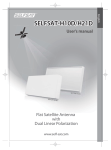
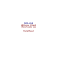
Block Diagram:-
ESA Ext.
PCIDIOT
Hardware
(Stepper Motor,
A/D Converters.)
PCI Slot
Digital I/O
ESA PCIDIOT
ESA PCIDIOT User Manual
End User
P.C
Page 3 of 60
2.0 DESCRIPTION OF THE CIRCUIT:
The card uses a popular PCI Bridge (U8) to interface, two 8255s at U5 & U6 and
one 8254 at U3, to the PC through PCI Bus. The two 8255s provide six
programmable 8-bit I/O ports.
The 24 I/O lines of U5 (8255-II) are brought to J4, a 26-pin male connector and
also to J3, a 25-pin D-type connector site.
The 24 I/O lines of U6 (8255-I) are brought to J2, a 26-pin male connector.
The 74LS245 at U9 is a Bi-directional buffer for data bus.
The PIT, 8254 at U3 has three 16-bit programmable timers /counters and can
operate up to 8 MHz. The OUT, GATE and CLK lines of the PIT are brought to
J1, a 15-pin D-Type female Connector. Please refer to Appendix C for all
connector details.
The jumpers JP1, JP2 and JP3 are used for connecting external or system clock
to the clock input of timer of 8254.
JUMPER
CONNECTION
JP1
JP2
JP3
CLOCK USED
1–2
EXT CLOCK to Timer 2
2–3
SYS CLOCK to Timer2
1–2
EXT CLOCK to Timer1
2–3
SYS CLOCK to Timer1
1–2
EXT CLOCK to Timer0
2–3
SYS CLOCK to Timer0
NOTE:
The GATE0, GATE1, GATE2 signals of the 8254 should be controlled by user as
per his requirements.
ESA PCIDIOT User Manual
Page 4 of 60
Packing List:
Before you begin installing ESA PCIDIOT Hardware, please make sure that the
following materials have been shipped to you.
Ø ESA PCIDIOT Hardware.
Ø ESA PCIDIOT Software CD containing Windows Driver Software &
Sample applications with source developed using VC++ 6.0, VB 6.0
Labwindows\CVI, MASM32, Turbo C & MASM.
Ø ESA PCIDIOT User’s Manual.
Minimum System Requirements:
Ø IBM Compatible Pentium machine or above.
Ø Windows 98/Windows NT/Windows 2000/ Windows XP/Windows Me.
Ø Microsoft Visual Studio / Lab Windows- CVI Development Environment.
Ø 64 MB of RAM.
Ø PCI Slot.
Ø CD-ROM Drive.
NOTE:
To use the ESA PCIDIOT card in Windows (98/NT/2000/XP) Environment user
need to install Windows driver software and library files available on the Driver
Software CD.
To use the card in DOS mode, please refer chapter 5.5 (DOS mode Application
Development).
ESA PCIDIOT User Manual
Page 5 of 60
3.0 Installation of the Hardware & Driver Software:
1. Switch off, the PC.
2. Remove the power cable from the PC.
3. Plug the ESA PCIDIOT card in the free PCI slot available on the PC
Motherboard.
4. Plug the power cable to the PC.
5. Switch on, the PC.
6. Windows OS will detect a new hardware and asks for the Installation of
Driver.
NOTE:
The user must have administrative privileges on the target computer in order
to install the driver for Windows 2000/XP/NT.
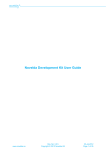
W
If user selects “Install the software automatically”, it will search for the suitable
drivers in local drives and external media. In Case it does not detect any suitable
driver, select “Install from a list or specific location”, you should then see the
following window.
ESA PCIDIOT User Manual
Page 6 of 60
ESA PCIDIOT User Manual
Page 7 of 60
After Installation is completed, run the following command from the Command
Prompt.
(WindowsXP)
G:\Driver\wdreg –inf C:\windows\system32\drivers\windrvr6.inf install
(Windows 2000)
G:\Driver\wdreg –inf C:\winnt\system32\drivers\windrvr6.inf install
(Windows 98)
G:\Driver\wdreg16 –inf C:\windows\system32\drivers\windrvr6.inf install
NOTE: Windows 98 requires a reboot after Installation of the driver for proper
working of the ESA PCIDIOT card.
Batch files for the above are provided in the Drivers CD, file names are reg98.bat
(Windows 98), reg2k.bat (Windows 2000) and regXP.bat (Windows XP).
User has to take care of the Drive names in the batch file while running these
batch files.
ESA PCIDIOT User Manual
Page 8 of 60
This Registering could be done for the reboot free installation of the Driver. This
could be done at the first time of installation; Next time onwards driver will be
activated automatically.
NOTE:
Windows NT Operating Systems doesn’t support Plug & Play feature. User
has to do manual installation of the driver for the card.
Go to the WINNT folder in the Drivers CD.
Edit “install.bat”. Confirm the Directory Paths of WINDOWS NT installation.
Edit “uninst.bat”. Confirm the Directory Paths.
For installing the driver, Double click on “install.bat” or run “install.bat” from the
command window.
For uninstalling the driver, close all the applications that are using this driver.
Double click on “uninst.bat” or run “uninst.bat” from the command windows.
Uninstalling the Driver:
Delete the Devices listed in Device Manager Under “ESA”(“Hardware” Tab
From “My Computer” Properties) like “ESA PCIDIOT” .
Delete “windrvr6.sys” & “windrvr6.inf” from “%windir%\system32\drivers”
Delete “esapdiot.dll” from “%windir%” (Ex: C:\Windows or C:\winnt)
Delete “oemxx.inf” (Windows2k/XP) from “%windir%\inf” directory or
“esa*.inf” from “%windir%\inf\other” (Windows 98).
Restart the PC.
NOTE:
On Windows 2000/XP/NT, the inf files will be created with “oemXX.inf” under
“%windir%\inf”. To find the inf file corresponding to ESA PCIDIOT card, user
can search the INF directory for the “ESA PCIDIOT” as a search text.
ESA PCIDIOT User Manual
Page 9 of 60
4.0 Driver Libraries Description:
Function Reference:
1) ESAPCIDIOT_Open()
PURPOSE
Provides Device Handle to access Driver kernel module. All other APIs use the
handle provided by this function, and therefore this function must be called before
calling any other API.
PROTOTYPE
int ESAPCIDIOT_Open(int CardNo)
PARAMETERS
Name
CardNo
Type
Input/Output
Int
Input
DESCRIPTION
Name
CardNo
Description
Used for specifying the card number
when multiple ESA PCIDIOT cards
present on the PC. If only one card
present on the PC, send ‘1’ as the card
number. Card Numbers will be known
from the PCI slots where ESA PCIDIOT
cards installed.
RETURN VALUE
Returns 0 on success,
1 if CardNo is not matching with the Existing ESAPCIDOT48 cards.
2 if No ESA PCIDIOT card existing.
ESA PCIDIOT User Manual
Page 10 of 60
EXAMPLE
int dwStatus;
dwStatus = ESAPCIDIOT_Open();
if (dwStatus == 2)
{
Message Box(NULL,” No ESA PCIDIOT Cards Found”,”ERROR”,NULL);
Exit(0);
}
if (dwStatus == 1)
{
Message Box(NULL,” Card No not matching with the existing
cards”,”ERROR”,NULL);
Exit(0);
}
if (dwStatus == 0)
{
Message Box(NULL,” Card Found”,” INFO…”,NULL);
…………..
………….
}
ESA PCIDIOT User Manual
Page 11 of 60
2) ESAPCIDIOT_Close()
PURPOSE
Closes the Device Handle and frees resources allocated for the Device which
was created by ESAPCIDIOT_Open() at start.
PROTOTYPE
void ESAPCIDIOT_Close()
PARAMETERS
None
RETURN VALUE
None
EXAMPLE
ESAPCIDIOT_Close();
ESA PCIDIOT User Manual
Page 12 of 60
3) Write_82551CR()
PURPOSE
Writes the data to the 8255-1(U6) Command Register of ESA PCIDIOT
Hardware.
PROTOTYPE
void Write_82551CR(unsigned char Data)
PARAMETERS
Name
Type
Input/Output
Data
unsigned char
Input
DESCRIPTION
Name
Data
Description
Used for specifying the data to be
written.
RETURN VALUE
NONE
EXAMPLE
Write_82551CR(0x80);
ESA PCIDIOT User Manual
Page 13 of 60
4) Write_82551PortA()
PURPOSE
Writes the data to the 8255-1(U6) PortA of ESA PCIDIOT Hardware.
PROTOTYPE
void Write_82551PortA(unsigned char Data)
PARAMETERS
Name
Type
Input/Output
Data
unsigned char
Input
DESCRIPTION
Name
Data
Description
Used for specifying the data to be
written.
RETURN VALUE
NONE
EXAMPLE
Write_82551PortA(0x80);
ESA PCIDIOT User Manual
Page 14 of 60
5) Write_82551PortB()
PURPOSE
Writes the data to the 8255-1(U6) PortB of ESA PCIDIOT Hardware.
PROTOTYPE
void Write_82551PortB(unsigned char Data)
PARAMETERS
Name
Type
Input/Output
Data
unsigned char
Input
DESCRIPTION
Name
Data
Description
Used for specifying the data to be
written.
RETURN VALUE
NONE
EXAMPLE
Write_82551PortB(0x80);
ESA PCIDIOT User Manual
Page 15 of 60
6) Write_82551PortC()
PURPOSE
Writes the data to the 8255-1(U6) PortC of ESA PCIDIOT Hardware.
PROTOTYPE
void Write_82551PortC(unsigned char Data)
PARAMETERS
Name
Type
Input/Output
Data
unsigned char
Input
DESCRIPTION
Name
Data
Description
Used for specifying the data to be
written.
RETURN VALUE
NONE
EXAMPLE
Write_82551PortC(0x80);
ESA PCIDIOT User Manual
Page 16 of 60
7) Read_82551PortA()
PURPOSE
Reads the data from the 8255-1(U6) PortA of ESA PCIDIOT Hardware.
PROTOTYPE
unsigned char Read_82551PortA(void)
PARAMETERS
NONE
RETURN VALUE
Returns the data read from the 8255-1(U6) PortA of ESA PCIDIOT Hardware.
EXAMPLE
Data = Read_82551PortA();
ESA PCIDIOT User Manual
Page 17 of 60
8) Read_82551PortB()
PURPOSE
Reads the data from the 8255-1(U6) PortB of ESA PCIDIOT Hardware.
PROTOTYPE
unsigned char Read_82551PortB(void)
PARAMETERS
NONE
RETURN VALUE
Returns the data read from the 8255-1(U6) PortB of ESA PCIDIOT Hardware.
EXAMPLE
Data = Read_82551PortB();
ESA PCIDIOT User Manual
Page 18 of 60
9) Read_82551PortC()
PURPOSE
Reads the data from the 8255-1(U6) PortC of ESA PCIDIOT Hardware.
PROTOTYPE
unsigned char Read_82551PortC(void)
PARAMETERS
NONE
RETURN VALUE
Returns the data read from the 8255-1(U6) PortC of ESA PCIDIOT Hardware.
EXAMPLE
Data = Read_82551PortC();
ESA PCIDIOT User Manual
Page 19 of 60
10) Write_82552CR()
PURPOSE
Writes the data to the 8255-2(U5) Command Register of ESA PCIDIOT
Hardware.
PROTOTYPE
void Write_82552CR(unsigned char Data)
PARAMETERS
Name
Type
Input/Output
Data
unsigned char
Input
DESCRIPTION
Name
Data
Description
Used for specifying the data to be
written.
RETURN VALUE
NONE
EXAMPLE
Write_82552CR(0x80);
ESA PCIDIOT User Manual
Page 20 of 60
11) Write_82552PortA()
PURPOSE
Writes the data to the 8255-2(U5) PortA of ESA PCIDIOT Hardware.
PROTOTYPE
void Write_82552PortA(unsigned char Data)
PARAMETERS
Name
Type
Input/Output
Data
unsigned char
Input
DESCRIPTION
Name
Data
Description
Used for specifying the data to be
written.
RETURN VALUE
NONE
EXAMPLE
Write_82552PortA(0x80);
ESA PCIDIOT User Manual
Page 21 of 60
12) Write_82552PortB()
PURPOSE
Writes the data to the 8255-2(U5) PortB of ESA PCIDIOT Hardware.
PROTOTYPE
void Write_82552PortB(unsigned char Data)
PARAMETERS
Name
Type
Input/Output
Data
unsigned char
Input
DESCRIPTION
Name
Data
Description
Used for specifying the data to be
written.
RETURN VALUE
NONE
EXAMPLE
Write_82552PortB(0x80);
ESA PCIDIOT User Manual
Page 22 of 60
13) Write_82552PortC()
PURPOSE
Writes the data to the 8255-2(U5) PortC of ESA PCIDIOT Hardware.
PROTOTYPE
void Write_82552PortC(unsigned char Data)
PARAMETERS
Name
Type
Input/Output
Data
unsigned char
Input
DESCRIPTION
Name
Data
Description
Used for specifying the data to be
written.
RETURN VALUE
NONE
EXAMPLE
Write_82552PortC(0x80);
ESA PCIDIOT User Manual
Page 23 of 60
14) Read_82552PortA()
PURPOSE
Reads the data from the 8255-2(U5) PortA of ESA PCIDIOT Hardware.
PROTOTYPE
unsigned char Read_82552PortA(void)
PARAMETERS
NONE
RETURN VALUE
Returns the data read from the 8255-2(U5) PortA of ESA PCIDIOT Hardware.
EXAMPLE
Data = Read_82552PortA();
ESA PCIDIOT User Manual
Page 24 of 60
15) Read_82552PortB()
PURPOSE
Reads the data from the 8255-2(U5) PortB of ESA PCIDIOT Hardware.
PROTOTYPE
unsigned char Read_82552PortB(void)
PARAMETERS
NONE
RETURN VALUE
Returns the data read from the 8255-2(U5) PortB of ESA PCIDIOT Hardware.
EXAMPLE
Data = Read_82552PortB();
ESA PCIDIOT User Manual
Page 25 of 60
16) Read_82552PortC()
PURPOSE
Reads the data from the 8255-2(U5) PortC of ESA PCIDIOT Hardware.
PROTOTYPE
unsigned char Read_82552PortC(void)
PARAMETERS
NONE
RETURN VALUE
Returns the data read from the 8255-2(U5) PortC of ESA PCIDIOT Hardware.
EXAMPLE
Data = Read_82552PortC();
ESA PCIDIOT User Manual
Page 26 of 60
17) Write_8254CR()
PURPOSE
Writes the data to the 8254(U3) Command Register of ESA PCIDIOT Hardware.
PROTOTYPE
void Write_8254CR(unsigned char Data)
PARAMETERS
Name
Type
Input/Output
Data
unsigned char
Input
DESCRIPTION
Name
Data
Description
Used for specifying the data to be
written.
RETURN VALUE
NONE
EXAMPLE
Write_8254CR(0x80);
ESA PCIDIOT User Manual
Page 27 of 60
18) Latch_Timer()
PURPOSE
Reads the data from specified 8254(U3) timers on the fly of ESA PCIDIOT
Hardware.
PROTOTYPE
unsigned short Latch_Timer(unsigned char Timerno)
PARAMETERS
Name
Timerno
Type
Input/Output
unsigned char
Input
0
---
Timer 0
1
---
Timer 1
2
---
Timer 2
RETURN VALUE
Returns the data read from the specified 8254(U3) Timer of ESA PCIDIOT
Hardware.
EXAMPLE
Data = Latch_Timer(0);
ESA PCIDIOT User Manual
Page 28 of 60
19) Write_Timer0()
PURPOSE
Writes the data to the 8254(U3) Timer0 of ESA PCIDIOT Hardware.
PROTOTYPE
void Write_Timer0(unsigned char Data)
PARAMETERS
Name
Type
Input/Output
Data
unsigned char
Input
DESCRIPTION
Name
Data
Description
Used for specifying the data to be
written.
RETURN VALUE
NONE
EXAMPLE
Write_Timer0(0x80);
ESA PCIDIOT User Manual
Page 29 of 60
20) Write_Timer1()
PURPOSE
Writes the data to the 8254(U3) Timer1 of ESA PCIDIOT Hardware.
PROTOTYPE
void Write_Timer1(unsigned char Data)
PARAMETERS
Name
Type
Input/Output
Data
unsigned char
Input
DESCRIPTION
Name
Data
Description
Used for specifying the data to be
written.
RETURN VALUE
NONE
EXAMPLE
Write_Timer1(0x80);
ESA PCIDIOT User Manual
Page 30 of 60
21) Write_Timer2()
PURPOSE
Writes the data to the 8254(U3) Timer2 of ESA PCIDIOT Hardware.
PROTOTYPE
void Write_Timer2(unsigned char Data)
PARAMETERS
Name
Type
Input/Output
Data
unsigned char
Input
DESCRIPTION
Name
Data
Description
Used for specifying the data to be
written.
RETURN VALUE
NONE
EXAMPLE
Write_Timer2(0x80);
ESA PCIDIOT User Manual
Page 31 of 60
22) Read_Timer0()
PURPOSE
Reads the data from the 8254(U3) Timer0 of ESA PCIDIOT Hardware.
PROTOTYPE
unsigned char Read_Timer0(void)
PARAMETERS
NONE
RETURN VALUE
Returns the data read from the 8254(U3) Timer0 of ESA PCIDIOT Hardware.
EXAMPLE
Data = Read_Timer0();
ESA PCIDIOT User Manual
Page 32 of 60
23) Read_Timer1()
PURPOSE
Reads the data from the 8254(U3) Timer1 of ESA PCIDIOT Hardware.
PROTOTYPE
unsigned char Read_Timer1(void)
PARAMETERS
NONE
RETURN VALUE
Returns the data read from the 8254(U3) Timer1 of ESA PCIDIOT Hardware.
EXAMPLE
Data = Read_Timer1();
ESA PCIDIOT User Manual
Page 33 of 60
24) Read_Timer2()
PURPOSE
Reads the data from the 8254(U3) Timer2 of ESA PCIDIOT Hardware.
PROTOTYPE
unsigned char Read_Timer2(void)
PARAMETERS
NONE
RETURN VALUE
Returns the data read from the 8254(U3) Timer2 of ESA PCIDIOT Hardware.
EXAMPLE
Data = Read_Timer2();
ESA PCIDIOT User Manual
Page 34 of 60
25) outportb()
PURPOSE
Write the BYTE data to the specified address. This address should be in the
address range of Selected Card resources. Use “Chkdiot” utility to know the Card
resources.
PROTOTYPE
void outportb(unsigned int PortAddr, unsigned char Data)
PARAMETERS
Name
Type
PortAddr
Data
Unsigned int
Unsigned Char
Input/Output
Input
Input
RETURN VALUE
NONE
EXAMPLE
Outportb(0xd803, 0x80);
ESA PCIDIOT User Manual
Page 35 of 60
26) inportb()
PURPOSE
Reads the BYTE data from the specified address. This address should be in the
address range of Selected Card resources. Use “Chkdiot” utility to know the Card
resources.
PROTOTYPE
unsigned char inportb(unsigned int PortAddr)
PARAMETERS
Name
PortAddr
Type
Unsigned int
Input/Output
Input
RETURN VALUE
Returns the data read from the specified address of ESA PCIDIOT Hardware.
EXAMPLE
Data = inportb(0x8000);
ESA PCIDIOT User Manual
Page 36 of 60
5.0 APPLICATION DEVELOPMENT USING DRIVER LIBRARIES:
•
Section I describes about the application development in VC++ 6.0.
•
Section II describes about the application development in VB 6.0.
•
Section III describes about the application development in
LabWindows/CVI.
•
Section IV describes about the application development in DOS mode
using Turbo C compiler/MASM
•
Section V describes about the application development in MASM32.
•
Section V describes about the application development in JAVA.
5.1) Visual C++ 6.0 (VC++)
Creating a New Console Application Project in Visual C++ 6.0:
1. Start the Microsoft Developer Studio.
2. Choose New from the File Menu.
3. Select Projects Tab. You should then see the following Dialog Box.
4. Enter the Project name and location where project-working folder should be
created.
5. Click OK button.
6. You should then see the following Dialog Box.
ESA PCIDIOT User Manual
Page 37 of 60
7. Select the Simple Application and click Finish.
8. Copy all Files from Lib folder available in Drivers CD to current working
directory.
9. Open the Application cpp file and add “#include “esapdiot.h” and
write the application using the Driver Libraries.
11.Select Project -> Settings. You should then see the following dialog box.
ESA PCIDIOT User Manual
Page 38 of 60
13. Select Link Tab in the Dialog box.
14. Specify “Esapdiot.lib” at Object/library modules Textbox.
15. Click OK button.
16. Build the Application From Build Menu.
17. Run the Application.
Example:
#include <stdafx.h>
#include “Esapdiot.h”
int main(void)
{
unsigned int dwError;
dwError = ESAPCIDIOT_Open();
Write_82551CR(0x80);
Write_82552CR(0x9b);
while(!kbhit()) {
Write_82551PortA(0x55);
Write_82551PortB(0xAA);
Write_82551PortB(0xFF);
if (Read_82552PortA() == 0x55)
printf(“\r\n PortA Good”);
Else
Printf(“\r\n PortA Bad”);
if (Read_82552PortB() == 0x55)
printf(“\r\n PortB Good”);
Else
Printf(“\r\n PortB Bad”);
if (Read_82552PortC() == 0x55)
printf(“\r\n PortC Good”);
Else
Printf(“\r\n PortC Bad”);
}
ESAPCIDIOT_Close();
return 0;
}
ESA PCIDIOT User Manual
Page 39 of 60
Creating a MFC Application Project in Visual C++ 6.0:
1. Start the Microsoft Developer Studio.
2. Choose New from the File Menu.
3. Select Projects Tab. You should then see the following Dialog Box.
4. Enter the Project name and location where project-working folder should be
created.
5. Click OK button.
6. You should then see the following Dialog Box.
ESA PCIDIOT User Manual
Page 40 of 60
7) Select Dialog based radio button and click Finish.
8) You should then see the following Dialog box with added classes
Information.
ESA PCIDIOT User Manual
Page 41 of 60
9) Click OK Button.
10) You should then see the following windows.
11) Add the controls as per requirement.
12) Add Callback functions for the controls by using the driver libraries.
13) Copy “esapdiot.h”, “esapdiot.dll” & “esapdiot.lib” Files from Lib folder, which
is available in Drivers CD.
14) Select Project -> Settings. Select Link Tab in the Dialog box.
15) Specify “Esapdiot.lib” at Object/library modules Textbox.
16) Click OK button.
17) Build the application from Build Menu.
18) Run the application.
Example Source is given in the Driver software CD under ExampleApp.Source
Folder.
ESA PCIDIOT User Manual
Page 42 of 60
5.2) Visual Basic 6.0 (VB)
Creating a Application Project in Visual BASIC 6.0:
1) Start Microsoft Visual Basic 6.0 environment.
2) Choose New Project from the File menu. You should then see the following
dialog.
3) Select Standard EXE and click OK Button.
4) copy “esapdiot.bas” & “esapdiot.dll” to the current project directory.
5) Add “esapdiot.bas” module to the current project by right clicking on the
project window -> add module option.
6) Place the controls( command button, text boxes etc..,) in the form.
7)Use the Driver Libraries as per the application requirement.
8) Build the Project
9) Run the application.
Example Source is given in the Driver software CD under ExampleApp.Source
Folder.
ESA PCIDIOT User Manual
Page 43 of 60
5.3) Lab Windows/CVI 6.0
Creating Project in Lab Windows/CVI 6.0:
1. Start the Lab Windows/CVI 6.0.
2. Create a new project in Lab Windows/CVI 6.0.
3. You should then see the following window.
4. Save the project.
5. Copy all Files from the Lib Folder, which are available on Drivers CD to the
current Project Directory.
6. Create a new uir file from File Menu.
7. You should then see the following window.
ESA PCIDIOT User Manual
Page 44 of 60
8. Right Click on the Panel and add the controls required. Add callbacks to the
controls.
9. Create new “C” source file and write the code using driver libraries.
10. Add .uir, .c & .lib files to the project from the Edit Menu.
11. Build the Application.
12. Run the Application.
Example Source is given in Drivers CD under “ExampleApp.Source” Folder.
ESA PCIDIOT User Manual
Page 45 of 60
5.4) DOS mode Application Development (TURBO C &
MASM)
NOTE: User can write applications using inportb & outportb function with
TURBO C Compiler (or) using IN & OUT instruction with MASM under
windows 98,Me & 95. Under Windows NT, 2000, XP the user mode
application does not have the permissions of the I/O ports. Please refer this
section to develop the applications under Windows NT, 2000, XP.
A problem that plagues Windows NT/2000 and Windows XP is it's strict control
over I/O ports. Unlike Windows 9x & ME, Windows NT/2000/XP will cause an
exception (Privileged Instruction) if an attempt is made to access an IO port that a
user mode program is not privileged to talk too. Actually it's not Windows NT that
does this, but any 386 or higher processor running in protected mode.
Accessing I/O Ports in protected mode is governed by two events, The I/O
privilege level (IOPL) in the EFLAGS register and the I/O permission bit map of a
Task State Segment (TSS). Under Windows NT, there are only two I/O privilege
levels used, level 0 & level 3. User mode programs will run in privilege level 3,
while device drivers and the kernel will run in privilege level 0, commonly referred
to as ring 0. This allows the trusted operating system and drivers running in
kernel mode to access the ports, while preventing less trusted user mode
processes from touching the I/O ports and causing conflicts. All user mode
programs should talk to a device driver, which arbitrates access. The I/O
permission bitmap can be used to allow programs not privileged enough (I.e. user
mode programs) the ability to access certain I/O ports. When an I/O instruction is
executed, the processors will first check if the task is privileged enough to access
the ports. Should this be the case, the I/O instruction will be executed. However if
the task is not allowed to do I/O, the processor will then check the I/O permission
bitmap. The I/O permission bitmap, as the name suggests uses a single bit to
represent each I/O address. If the bit corresponding to a port is set, then the
instruction will generate an exception however if the bit is clear then the I/O
operation will proceed. This gives a means to allow certain processes to access
certain ports. There is one I/O permission bitmap per task.
ESA PCIDIOT User Manual
Page 46 of 60
Accessing I/O Ports under NT/2000/XP
There are two solutions to solving the problem of I/O access under Windows
NT/2000/XP. The first solution is to write a device driver, which runs in ring 0 (I/O
privilege level 0) to access your I/O ports on your behalf. Data can be passed to
and from your user mode program to the device driver via IOCTL calls. The driver
can then execute your I/O instructions. The problem with this is that it assumes
you have the source code to make such a change.
For this user has to use the drivers given along with ESA PCIDIOT card under
“Lib” folder. User has to use Microsoft Visual Studio or Labwindows/Cvi to use
these libraries. Procedure to develop the applications with these libraries and
library description was given in the User Manual. Example application sources
are also available with the CD.
Another possible alternative is to modify the I/O permission bitmap to allow a
particular task, access to certain I/O ports. This grants your user mode program
running in ring 3 to do unrestricted I/O operations on selected ports, as per the
I/O permission bitmap.
This method is not really recommended, but provides a means of allowing
existing applications to run under windows NT/2000/XP. Using the device driver
provided with ESA PCIDIOT hardware is the preferred method.
For this,
1) User has to copy the files given under MASM_TC folder in ESA PCIDIOT
Drivers CD to the current working directory.
2) Run “Chkdiot” utility, which was given in Drivers CD to know the base address,
assigned for the Card Resources.
3) Write the application with MASM using IN & OUT instruction to access the card
resources. If you are using TURBO C, use “inport & outport” functions to access
card resources.
ESA PCIDIOT User Manual
Page 47 of 60
4) Generate the “xxxxxxx.exe” file.
5) Run “iopm xxxxxxx.exe” 0xd800 0xdc00 0xdf00 + Enter key
Ex:
0xd800 -- Base Address for 8255-1
0xdc00 -- Base Address for 8255-2
0xdf00
-- Base Address for 8254
This could be done at the first run of the application. From Next run onwards till
the PC restart use can run his applications without “iopm”.
i.e. “xxxxxxxx.exe” + enter
NOTE: The above procedure should be followed when user is having Windows
NT, 2000, XP Operating System. Under Windows 98 & 95 user can run his
applications developed with MASM or TURBO C without any problem.
6) Run “uninstall.exe” to uninstall “EsaIopm” Service.
Creating Application in TURBOC:
1) Run the “Chkdiot” utility from Drivers CD to know the ESA PCIDOT Card
resources. This utility lists the
i) 8255-1 & 8255-2 Command Register, PortA, PortB & PortC Address
ii) 8254 Timer Command Register, Timer0, Timer1 & Timer2 Address.
iii) Number of ESA PCIDIOT Cards Existing.
2) Open the Turbo C editor and create a new file. Use the listed addresses
of the card resources with inportb() & outportb() libraries, which is
available under “dos.h”.
ESA PCIDIOT User Manual
Page 48 of 60
EXAMPLE:
#include <stdio.h>
#include <dos.h>
void main(void)
{
// Make 8255-1 all port outports
outportb(0xd803,0x80);
// Make 8255-2 all port imports
outportb(0xdc03,0x9b);
while (!kbhit())
{
outportb(0xd800,0x55);
if (inportb(0xdc00) == 0x55)
printf(“PortA Good”);
}
}
More Examples was given in the ESA PCIDIOT Drivers CD.
MASM Examples are also given in the CD.
ESA PCIDIOT User Manual
Page 49 of 60
5.5) MASM32 Application Development
Copy files from MASM32LIB folder to current working directory.
Include esadiot.inc to your application.
Write the application using the libraries included in “esadiot.inc”
Please refer the examples given in MASM32 folder of Driver CD. “Makeit.bat”
contains the assembler and linker commands.
5.6) JAVA Application Development
Copy all files from java folder to current working directory.
Create object for EsaJDiot class in your application.
Write the application using the methods available in EsaJDiot class.
(For methods please refer “EsaJDiot.java”)
Compile code using “javac” and run using “java” commands
Please refer the examples given in java folder of Driver CD.
Known Limitations:Cannot be used with Applets.
Application may not work in Cross Operating system (Linux/solaris …)
ESA PCIDIOT User Manual
Page 50 of 60
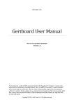
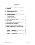
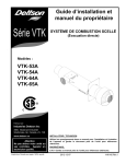
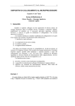
Appendix A
Schematics
1
10
27
41
50
66
81
103
121
146
VCC
AD0
AD1
AD2
AD3
AD4
AD5
AD6
AD7
AD8
AD9
AD10
AD11
AD12
AD13
AD14
AD15
AD16
AD17
AD18
AD19
AD20
AD21
AD22
AD23
AD24
AD25
AD26
AD27
AD28
AD29
AD30
AD31
LW/R
CSO
LBE0
LBE1
U8
RD*
WR*
LRESET
CS1
C/BE0
C/BE1
C/BE2
C/BE3
CS2
CS3
159
21
149
IOSEL
PAR
CLK
LINTI1
LINTI2
[1]
[1]
[1]
[1]
EECS
EESK
EEDI
EEDO
142
144
145
143
99
R8
10K
LA4
STOP
PERR
SERR
INTA
RST
LA7
LA5
LA6
LA8
LCLK
EECS
EESK
EEDI
EEDO
TEST
BCLK0
MODE
VSS
VSS
VSS
VSS
VSS
VSS
VSS
VSS
VSS
VSS
17
19
20
44
148
FRAME
DEVSEL
IRDY
TRDY
LOCK
9
26
40
51
65
80
104
120
147
160
13
16
14
15
18
P1A(0...7)
[2]
LAD0
LAD1
LAD2
LAD3
LAD4
LAD5
LAD6
LAD7
LA2
LA3
PCI 9052
33
22
12
158
D[0...7]
VDD
VDD
VDD
VDD
VDD
VDD
VDD
VDD
VDD
VDD
43
42
39
38
37
36
35
34
32
31
30
29
28
25
24
23
11
8
7
6
5
4
3
2
157
156
155
154
153
152
151
150
91
90
89
88
87
86
85
84
92
93
2
3
4
5
6
7
8
9
19
1
A1
A2
A3
A4
A5
A6
A7
A8
18
17
16
15
14
13
12
11
B1
B2
B3
B4
B5
B6
B7
B8
U9
34
33
32
31
30
29
28
27
5
36
9
8
35
6
G
DIR
74LS245
127
130
D0
D1
D2
D3
D4
D5
D6
D7
PA0
PA1
PA2
PA3
PA4
PA5
PA6
PA7
U6
RD
WR
A0
A1
RESET
CS
PB0
PB1
PB2
PB3
PB4
PB5
PB6
PB7
49
PC0
PC1
PC2
PC3
PC4
PC5
PC6
PC7
48
126
125
4
3
2
1
40
39
38
37
P1A0
P1A1
P1A2
P1A3
P1A4
P1A5
P1A6
P1A7
18
19
20
21
22
23
24
25
P1B0
P1B1
P1B2
P1B3
P1B4
P1B5
P1B6
P1B7
14
15
16
17
13
12
11
10
P1C0
P1C1
P1C2
P1C3
P1C4
P1C5
P1C6
P1C7
[2]
P1B(0...7)
[2]
P1C(0...7)
[2]
8255--I
132
131
1
CS1*
RESET
2
CS2*
VCC
[2]
74LS14
[1] EECS
[1] EESK
[1] EED I
VCC [1] EED0
[2]
140
141
U1A
[2]
1
2
3
4
8
E626 76
5
R2 10K
R3 10K
137
R1 10K
136
U1D
94
VCC
95
9
97
3
4
5
6
98
135
63
68
R9
SYSCLK /4
8
[2]
74LS14
96
R10
22E
10K
7
10
2
9
1
A
B
C
D
QA
QB
QC
U2 QD
RCO
ENP
ENT
CLK
LOAD
CLR
74LS163
14
13
12
11
15
U1C
5
SYSCLK /8
6
[2]
74LS14
U1B
3
4
SYSCLK /16
[2]
74LS14
ESA PVT LTD BANGALORE
Title
ESA PCIDIOT
Size
Document Number
Date:Tuesday, January 03, 2006
ESA PCIDIOT User Manual
Rev
Sheet
1 of 2
Page 51 of 60
[1]
[2]
D[0...7]
34
33
32
31
30
29
28
27
RD*
[1]
WR*
[1]
[1] LBE0*
[1] LBE1*
[1] RESET
[1] CS1*
D0
D1
D2
D3
D4
D5
D6
D7
5
36
9
8
35
6
PA0
PA1
PA2
PA3
PA4
PA5
PA6
PA7
U5
RD
WR
A0
A1
RESET
CS
PB0
PB1
PB2
PB3
PB4
PB5
PB6
PB7
PC0
PC1
PC2
PC3
PC4
PC5
PC6
PC7
4
3
2
1
40
39
38
37
P2A0
P2A1
P2A2
P2A3
P2A4
P2A5
P2A6
P2A7
P2A[0...7]
18
19
20
21
22
23
24
25
P2B0
P2B1
P2B2
P2B3
P2B4
P2B5
P2B6
P2B7
P2B[0...7]
14
15
16
17
13
12
11
10
P2C0
P2C1
P2C2
P2C3
P2C4
P2C5
P2C6
P2C7
P2C[0...7]
[2]
[1]
[1]
[1]
[1]
[1]
[1]
[1]
[1]
[1]
[1]
[1]
VCC [1]
P1C4
P1C2
P1C0
P1B6
P1B4
P1B2
P1B0
P1A6
P1A4
P1A2
P1A0
P1C6
1
3
5
7
9
11
13
15
17
19
21
23
25
J2
2
4
6
8
10
12
14
16
18
20
22
24
26
P1C5 [1]
P1C3 [1]
P1C1 [1]
P1B7 [1]
P1B5 [1]
P1B3 [1]
P1B1 [1]
P1A7 [1]
P1A5 [1]
P1A3 [1]
P1A1 [1]
P IC7 [1]
[2]
[2]
[2]
[2]
[2]
[2]
[2]
[2]
[2]
[2]
[2]
VCC [2]
P2C4
P2C2
P2C0
P2B6
P2B4
P2B2
P2B0
P2A6
P2A4
P2A2
P2A0
P2C6
CON26A
[2]
8
15
7
14
6
13
5
12
4
11
3
10
2
9
1
22
23
19
20
[1]
21
CLK0
G0
OUT0
U10
RD
WR
A0
A1
CLK1
G1
OUT1
CLK2
G2
OUT2
15
14
13
18
16
17
2
JP3
1
GATE 0
OUT 0
J3
P2B0
EXTCLK 1
SYSCLK/4 [1]
3
2
15PIN "D" FE MALE
SYSCLK/8 [1]
JP2
1
GATE 1
OUT1
[2] OUT 0
EXTCLK 0
3
2
[2] GATE 0
SYSCLK/16[1]
3
9
11
10
JP1
1
CS
VCC
C1
0.1MF
C2
0.1MF
C3
0.1MF
3.3V
+12V
C4
0.1MF
C5
0.1MF
C6
0.1MF
C7
0.1MF
C8
0.1MF
C9
0.1MF
C10
0.1MF
C11
0.1MF
C14
0.1MF
C15
10MF
13
25
12
24
11
23
10
22
9
21
8
20
7
19
6
18
5
17
4
16
3
15
2
14
1
P2B3
P2C7
P2B2
P2C6
P2B5
P2A1
P2B4
P2A0
P2B7
P2A3
P2B6
P2A2
P2C1
P2A5
P2C0
P2A4
P2C3
P2A7
P2C2
P2A6
P2C5
P2B1
P2C4
EXTCLK 2
GATE 2
OUT 2
8254
CS2*
P2C5 [2]
P2C3 [2]
P2C1 [2]
P2B7 [2]
P2B5 [2]
P2B3 [2]
P2B1 [2]
P2A7 [2]
P2A5 [2]
P2A3 [2]
P2A1 [2]
P2C7 [2]
2
4
6
8
10
12
14
16
18
20
22
24
26
J1
EXTCLK 2
GATE 1
EXTCLK 1
OUT 1
EXTCLK 0
GATE 2
SYSCLK/16
OUT 2
SYSCLK/ 8
[1] SYSCLK/ 4
D0
D1
D2
D3
D4
D5
D6
D7
J4
CON26A
[2]
[2]
[2]
[2]
[2]
[2]
[1]
[2]
[1]
8255--II
8
7
6
5
4
3
2
1
1
3
5
7
9
11
13
15
17
19
21
23
25
C16
0.1MF
25PIN 'D' FEMALE
-12V
ESA PVT LTD BANGALORE
Title
C13
0.1MF
C17
0.1MF
C12
0.1MF
ESA PCIDIOT
Size
Document Number
Date: Friday, January 27, 2006
ESA PCIDIOT User Manual
Rev
Sheet
2 of 2
Page 52 of 60
Appendix B
Component Layout
ESA PCIDIOT User Manual
Page 53 of 60
Appendix C
Connector Details
15 Pin D-Type Female Connector for 8254 Timer (J1):-
Signal
OUT 0
GATE 0
SYSCLK/4
SYSCLK/8
SYSCLK/16
EXTCLK 0
EXTCLK1
EXTCLK 2
NC
NC
GND
OUT 2
GATE 2
OUT1
GATE 1
ESA PCIDIOT User Manual
15-Pin Female
Connector
1
2
3
4
5
6
7
8
9
10
11
12
13
14
15
Page 54 of 60
26 Pin Right Header Box Connector (J2):--
Signal
P1A0
P1A1
P1A2
P1A3
P1A4
P1A5
P1A6
P1A7
P1B0
P1B1
P1B2
P1B3
P1B4
P1B5
P1B6
P1B7
P1C0
P1C1
P1C2
P1C3
P1C4
P1C5
P1C6
P1C7
VCC
GND
ESA PCIDIOT User Manual
8255
(U6)
4
3
2
1
40
39
38
37
18
19
20
21
22
23
24
25
14
15
16
17
13
12
11
10
26
7
26 PIN Connector
(J2)
21
22
19
20
17
18
15
16
13
14
11
12
9
10
7
8
5
6
3
4
1
2
23
24
25
26
Page 55 of 60
26 Pin Right Header Box Connector (J4):--
Signal
P2A0
P2A1
P2A2
P2A3
P2A4
P2A5
P2A6
P2A7
P2B0
P2B1
P2B2
P2B3
P2B4
P2B5
P2B6
P2B7
P2C0
P2C1
P2C2
P2C3
P2C4
P2C5
P2C6
P2C7
VCC
GND
ESA PCIDIOT User Manual
8255
(U5)
4
3
2
1
40
39
38
37
18
19
20
21
22
23
24
25
14
15
16
17
13
12
11
10
26
7
26 PIN Connector
(J4)
21
22
19
20
17
18
15
16
13
14
11
12
9
10
7
8
5
6
3
4
1
2
23
24
25
26
Page 56 of 60
Solder Side PCI Signal Details:Pin
+5V
Description
1
TRST
Test Logic Reset
2
+12V
+12 VDC
3
TMS
Test Mode Select
4
TDI
Test Data Input
5
+5V
+5 VDC
6
INTA
Interrupt A
7
INTC
Interrupt C
8
+5V
+5 VDC
9 RESV01 Reserved VDC
10
+5V
+V I/O (+5 V or +3.3 V)
11 RESV03 Reserved VDC
12 GND03 Ground or Open (Key)
13 GND05 Ground or Open (Key)
14 RESV05 Reserved VDC
15 RESET Reset
16
+5V
+V I/O (+5 V or +3.3 V)
17
GNT
Grant PCI use
18 GND08 Ground
19 RESV06 Reserved VDC
20
AD30
Address/Data 30
21 +3.3V01 +3.3 VDC
22
AD28
Address/Data 28
23
AD26
Address/Data 26
24 GND10 Ground
25
AD24
Address/Data 24
26
IDSEL Initialization Device Select
27 +3.3V03 +3.3 VDC
28
AD22
Address/Data 22
29
AD20
Address/Data 20
30 GND12 Ground
31
AD18
Address/Data 18
32
AD16
Address/Data 16
33 +3.3V05 +3.3 VDC
ESA PCIDIOT User Manual
Page 57 of 60
34 FRAME Address or Data phase
35 GND14 Ground
36
TRDY Target Ready
37 GND15 Ground
38
STOP Stop Transfer Cycle
39 +3.3V07 +3.3 VDC
40 SDONE Snoop Done
41
SBO
Snoop Back off
42 GND17 Ground
43
PAR
Parity
44
AD15
Address/Data 15
45 +3.3V10 +3.3 VDC
46
AD13
Address/Data 13
47
AD11
Address/Data 11
48 GND19 Ground
49
52
AD9
Address/Data 9
C/BE0 Command, Byte Enable 0
53 +3.3V11 +3.3 VDC
54
AD6
Address/Data 6
55
AD4
Address/Data 4
56 GND21 Ground
57
AD2
Address/Data 2
58
AD0
Address/Data 0
59
+5V
+V I/O (+5 V or +3.3 V)
60 REQ64 Request 64 bit`
61 VCC11 +5 VDC
62 VCC13 +5 VDC
ESA PCIDIOT User Manual
Page 58 of 60
Component Side PCI Signal Details:-
2
-12V
TCK
-12 VDC
Test Clock
3
GND
Ground
4
TDO
Test Data Output
5
+5V
+5 VDC
6
+5V
+5 VDC
7
INTB
Interrupt B
8
INTD
Interrupt D
1
9 PRSNT1 Reserved
10
RES
+V I/O (+5 V or +3.3 V)
11 PRSNT2
12
GND
Ground or Open (Key)
13
GND
Ground or Open (Key)
14
RES
Reserved VDC
15
GND
Reset
16
CLK
Clock
17
GND
Ground
18
REQ
Request
19
+5V
+V I/O (+5 V or +3.3 V)
20
AD31
Address/Data 31
21
AD29
Address/Data 29
22
GND
Ground
23
AD27
Address/Data 27
24
AD25
Address/Data 25
25 +3.3V
+3.3VDC
26 C/BE3 Command, Byte Enable 3
27
AD23
Address/Data 23
28
GND
Ground
29
AD21
Address/Data 21
30
AD19
Address/Data 19
31 +3.3V
+3.3 VDC
32
Address/Data 17
AD17
33 C/BE2 Command, Byte Enable 2
34 GND13 Ground
ESA PCIDIOT User Manual
Page 59 of 60
35
IRDY
Initiator Ready
36 +3.3V06 +3.3 VDC
37 DEVSEL Device Select
38 GND16 Ground
39 LOCK Lock bus
40 PERR Parity Error
41 +3.3V08 +3.3 VDC
42 SERR System Error
43 +3.3V09 +3.3 VDC
44 C/BE1 Command, Byte Enable 1
45
AD14
Address/Data 14
46 GND18 Ground
47
AD12
Address/Data 12
48
AD10
Address/Data 10
49 GND20 Ground
50 (OPEN) Ground or Open (Key)
51 (OPEN) Ground or Open (Key)
52
AD8
Address/Data 8
53
AD7
Address/Data 7
54 +3.3V12 +3.3 VDC
55
AD5
Address/Data 5
56
AD3
Address/Data 3
57 GND22 Ground
58
AD1
Address/Data 1
59 VCC08 +5 VDC
60 ACK64 Acknowledge 64 bit
61 VCC10 +5 VDC
62 VCC12 +5 VDC
ESA PCIDIOT User Manual
Page 60 of 60