Download Leaflet - Programmable logic relays KINCO
Transcript
Programmable
logic relays
100% electricity
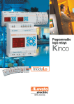
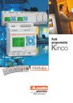
Programmable logic relays
, LOVATO Electric system of modular
components, has been still more enhanced with the
introduction of
: a programmable logic relay,
compact in size yet with excellent performance,
suitable for the control and supervision of low and
medium complexity automatisms.
Due to the multiplicity of functions,
can
efficiently be used in diverse fields of industrial,
service and residential applications.
Packaging machines, industrial dishwashers, lighting
installations, irrigation systems, garbage disposal
machinery, door and gate controls are just a few
examples of where
can be used.
Small
Smart
Simple
Expandable
Versatile
Programming
At any time and with extreme simplicity,
can be set up and
reprogrammed to satisfy new requirements and improve the operation of a system.
Programming is simple and intuitive and can be done directly on
the relay keypad or by personal computer, connected by LRX C00
interface and using the relative LRX SW software.
Base unit inputs state
123456789ABC
RUN
MO 1 0 : 3 1
Base unit outputs state
Date and time LRD state
I/O STATUS
DATA
Expansion inputs state
KEY
123456789ABC
19 . 09 . 05
Expansion outputs state
Date
MENU
LADDER ---------FBD -------------RUN -------------CLEAR PROG. --WRITE-----------READ -------------
I/O STATUS
1123456789ABC
DEF
-
Memory, timer, counter,
RTC and analog
comparator state
PLC STATUS
KEY
ESC
TIME
A
A
A
A
1=1
2=0
3=2
4=6
.
.
.
.
2
0
4
5
5
0
0
9
Value of analog inputs
A
A
A
A
5=5
6=0
7=2
8=8
.
.
.
.
3
1
7
3
5
0
0
2
Value of analog inputs
SET--------------- 7
RTC SET --------- 8
ANALOG SET ---- 9
PASSWORD----- 10
LANGUAGE ----- 11
INITIAL --------- 12
1
2
3
4
5
6
KEY
Analogs
STATUS 1
7
1
Programming
with the keypad is quite simple and straight
forward, without particular programming knowledge. There are
8 function keys on the relay front, dedicated to on-board adjustment,
control and supervision of digital input and output status, analog
input values, time and date entry and the operation status of the
relay itself.
Programming sequences are shown on a backlit 4-line 12-character display.
When using a Personal Computer (PC), two common language
logics are available for programming:
Function Block Diagram (FBD) and LADDER (contact scheme).
Using the Simulator option, the user can control the exactness of
the implemented program in off-line simulation, directly on the PC,
before the on-line testing and the system set-up.
I 1 -M1 - - - - ( Q 1
I 2Q 1 - m1 - - - - ( T 1
8
1
2
1
10 . 00
RUN
3
T1
9
PROG .
>YES
NO
10
CLEAR
4
11
>YES
NO
READ
6
>YES
NO
RTC SET V1 . 4
05 . 09 . 19
MO 1 3 : 4 3
A 1=GA
OFFS
A 2=GA
OFFS
A 3=GA
OFFS
A 4=GA
OFFS
I
E
I
E
I
E
I
E
N
T
N
T
N
T
N
T
:
:
:
:
:
:
:
:
01
+0
01
+0
01
+0
01
+0
P A S SWO R D
0000
PROG .
>YES
NO
WR I T E
5
I D SET
01
R EMO T E I \ O N
BACKL I GHT
x
M KEEP
√
I \ O N UMB E R : 0
I \ O A L A RM : √
C KEEP
x
ENGL I SH
FRANCA I S
ESPANOL
I TA L I ANO
DEUTCH
PORTUGUES
CH I NESE
I N I T I AL
12
>L ADDER
FBD
0
0
0
0
0
0
0
0
x
Small relay
Exceptional performance
Applications
Residential and home
automation
Industrial buildings
• Lighting
• Alarm and fire systems
• Garden irrigation and pool filling
systems
• Heating and air-conditioning
control
• Shutter and roller shutter control.
• Automatic door, gate or window
opening and closing
• Boiler and heating control
• Ventilation and air conditioning
• Alarm and fire systems
• Lighting.
Cold storage and
refrigeration
Industrial machinery
•
•
•
•
•
•
•
Compressor, motor, pump control
Industrial washing machines
Mixers and blenders
Garbage shedders and compactors
Car washing systems
Bending machines
Welding machines.
•
•
•
•
Timers
Temperature control
Humidity and ventilation control
Compressor control.
Main features
• Available power supply: 24VDC or 24VAC or 100-240VAC units
• 10, 12 and 20 input-output base units
• Expansion models with 4 inputs and 4 outputs
• Maximum configuration: 44 inputs/outputs
• 8A Ith current relay outputs for AC and DC versions
• 0.3A 24VDC transistor outputs for DC version
• 0-10V analog inputs for DC version
• Standard-supplied Real Time Clock (RTC)
• RS232 serial interface port for PC or program back-up memory
connection
• 4-line 12-character display with backlight
• Programming language logics: Ladder (200 lines maximum;
5-20ms sampling time) or FBD (99 blocks maximum; 2-10ms
sampling time)
• On-board programming languages: Italian, English, Spanish,
French, German, Portuguese and Chinese
• PC programming languages: Italian, English and Spanish
• Modular housing with 35mm DIN rail mount or screw fixing on
mounting plate.
Accessories and communication module
• The LRX 1V3 D024 power supply produces a direct-current voltage to
power the
base and expansion modules in circumstances when
24VDC is not available in the application. The power supply can also be
used to power eventual 24VDC auxiliary circuits.
combines the facility of numerous traditional devices, such as controls relays, timers, counters, hour
meters and so on.
The advantages are many: cost reduc-
is available for 24VDC or 24VAC
or 100-240VAC power supply and with
10 to 44 inputs and outputs.
tion of materials and installation time,
space reduction, easy reprogramming
when needed, and function adjustment
of the system for relay adaptation to
new installation requirements.
Applications
Conveying and transfer
systems
•
•
•
•
•
Conveyor belts
Stop and go controls
Automatic programmed stopping
Luggage belts
Storage and car silos.
Level and pressure
control
Greenhouses
• Automatic valve opening and • Lighting
closing control
• Temperature control
• Level controls
• Humidity control
• Pressure controls
• Irrigation
• Pump change
• Sprinkling systems.
• Storage silo and tank filling and
draining.
Lifting mechanisms
•
•
•
•
•
Bridge crane control
Roadway barriers and gates
Automatic car garages
Platforms
Hoists and lifts.
Expansion modules
can be easily adapted to every type of need. The number of
inputs and outputs of the base relay unit can be directly increased by
using the expansion modules.
Supplied in three base units with 10, 12 or 20 inputs/outputs,
can be expanded mounting up to 3 expansion modules, to
obtain a maximum configuration of 44 inputs/outputs.
LRD10…
LRD12…
LRD10…
• The LRX M00 backup memory consents to save the user’s program and
to simply and quickly transfer it to other
base modules.
• The LRE P00 expansion implements communications using Modbus®
protocol.
LRD12…
LRD20…
LRD20…
LRE08…
Expansions
Inputs/Outputs
+ LRE08
+ LRE08 + LRE08
+ LRE08 + LRE08 + LRE08
10 (6 Inputs +
18 (10 Inputs +
26 (14 Inputs +
34 (18 Inputs +
4
8
12
16
Outputs)
Outputs)
Outputs)
Outputs)
+ LRE08
+ LRE08 + LRE08
+ LRE08 + LRE08 + LRE08
12 (8 Inputs +
20 (12 Inputs +
28 (16 Inputs +
36 (20 Inputs +
4
8
12
16
Outputs)
Outputs)
Outputs)
Outputs)
+ LRE08
+ LRE08 + LRE08
+ LRE08 + LRE08 + LRE08
20
28
36
44
8
12
16
20
Outputs)
Outputs)
Outputs)
Outputs)
(12
(16
(20
(24
Inputs
Inputs
Inputs
Inputs
+
+
+
+
How to order
Order code
Power supply
Digital
Total n°
INPUTS
Digital/Analog (0-10VDC) ❶
n°
Base relay unit
LRD12R D024
24VDC
6
2
LRD12T D024
24VDC
6
2
LRD20R D024
24VDC
8
4
LRD20T D024
24VDC
8
4
LRD12R A024
24VAC
8
0
LRD20R A024
24VAC
12
0
LRD10R A240
100-240VAC
6
0
LRD20R A240
100-240VAC
12
0
Expansion and communication modules
LRE08R D024
24VDC
4
0
LRE08T D024
24VDC
4
0
LRE08R A024
24VAC
4
0
LRE08R A240
100-240VAC
4
0
LRE P00
Modbus® protocol communication unit
Accessories
LRX M00
Program backup memory
LRX C00
PC-LRD connecting cable, 1.5m long
LRX SW
Programming and supervision software (cd-rom)
LRX 1V3 D024
Power supply unit, 100-240VAC/24VDC, 1.3A
LRX D00
User’s manual Italian edition (paper)
LRX D01
User’s manual English edition (paper)
LRX D02
User’s manual Spanish edition (paper)
Starter kits
LRDKIT 12R D024
LRD starter kit complete with LRD12R D024 relay, LRX SW software and LRX C00 cable
LRDKIT 12R A024
LRD starter kit complete with LRD12R A024 relay, LRX SW software and LRX C00 cable
LRDKIT 10R A240
LRD starter kit complete with LRD10R A240 relay, LRX SW software and LRX C00 cable
Digital
OUTPUTS
RTC
n°
Type
4
4
8
8
4
8
4
8
Relay
Transistor
Relay
Transistor
Relay
Relay
Relay
Relay
Yes
Yes
Yes
Yes
Yes
Yes
Yes
Yes
4
4
4
4
Relay
Transistor
Relay
Relay
No
No
No
No
Technical characteristics
Power supply
Rated utilisation voltage Ue (Frequency range)
Operating limits
Digital inputs
Rated voltage
State 0
Input voltage
State 1
0 to 1
Delay time
1 to 0
Analog inputs for 24VDC version only
Input signal range
Display resolution
Conversion
Current consumption at 10VDC
Input impedance
Admissible overload
Maximum cable length
Digital outputs
Type of output / Rated current Ith
Applied voltage
Ambient conditions
Operating / Storage temperature
Relative humidity
Maximum pollution degree
Housing
Version
Type of terminal
Conductor section
Connections
Tightening torque
Maximum cable length
LRD10… / LRD12…
Dimensions (wxhxd)
LRD20…
Expansions LRE…
Degree of protection
Certfications and compliance
❶ Digital inputs can be used as analog inputs.
LRD…D024
24VDC
20.4-28.8VDC
LRD…A024
24VAC
-
LRD…A240
100-240VAC (50-60Hz)
85-264VAC
24VDC
< 5VDC / < 0.625mA
> 15VDC / > 1.875mA
3-5ms
3-5ms
24VAC
❷
❷
❷
❷
110-220VAC
< 40VAC / < 0.28mA (LRD10R A240) < 0.15mA (LRD20R A240)
> 79VAC / > 0.41mA
45-50ms (Ue=100VAC) – 18-22ms (Ue=240VAC)
45-50ms (Ue=100VAC) – 85-90ms (Ue=240VAC)
0-10V
0.01V
10bit
< 0.17mA
< 1kΩ
28VDC
≤ 30m of screened type
LRD…R… / LRE08R…
Relay / 8A
12-240VAC / 12-125VDC
-
LRD…T… / LRE08T…
Transistor / 0.3A 24VDC
21.6-26.4VDC
-20…+55°C / -40…+70°C
20-90%, without condensation
2
Modular for mounting on 35mm DIN rail (IEC/EN 60715) or M4x15mm screw fixing
Screw
0.75-3.5mm2/ 12 AWG
0.4-0.6Nm/0.3-0.4lbft
≤ 100m
72x106x57.3mm
126x106x57.3mm
38x106x57.3mm
IP20
Certfications obtained: cULus; compliant with standards: IEC/EN 61131-2
❷ Contact our Customer Service (Tel. +39 035 4282422) for details.


