1
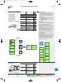
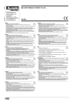
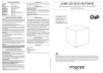
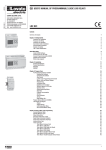
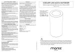
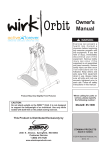
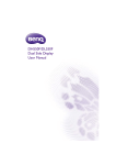
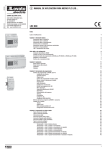
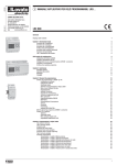
20_Capitolo_20GB.qxd
3-03-2009
13:09
Pagina 1
20
PROGRAMMABLE
RELAYS
• 10 Inputs/Outputs (LRD1D...)
12 Inputs/Outputs (LRD12...)
10 Inputs/Outputs (LRD20...)
• 24VDC, 24VAC or 100-240VAC power supply
• Relay or transistor outputs.
PAGE 20-2
EXPANSION AND COMMUNICATION MODULES
• 8 Inputs/Outputs
• 24VDC, 24VAC or 100-240VAC
• Relay or transistor outputs
• Modbus® protocol communication unit.
PAGE 20-3
ACCESSORIES
• Program backup memory
• Programming and supervision software
• Power supply unit.
10, 12 and 20 Input-Output base
units
Expansion modules with 4 Inputs
and 4 Outputs
Maximum configuration:
44 Inputs/Outputs
RS232 serial interface port for
PC or program backup memory
connection
On-board programming
languages: Italian, English,
Spanish, French, German,
Portuguese and Chinese
PC programming languages:
Italian, English and Spanish.
PLANET - LOGIC
PAGE 20-2
LOGIC RELAYS
Programmable logic relays
Base relay unit . . . . . . . . . . . . . . . . . . . . . . . . . . . . . . . . . . . . . . . . . . . . . . . . . .
Expansion and communication modules . . . . . . . . . . . . . . . . . . . . . . . . . . . . . . .
Accessories . . . . . . . . . . . . . . . . . . . . . . . . . . . . . . . . . . . . . . . . . . . . . . . . .
Starter kits . . . . . . . . . . . . . . . . . . . . . . . . . . . . . . . . . . . . . . . . . . . . . . . . . .
PAGE 20-3
STARTER KITS
• Complete kit to begin using the programmable
relays
• Each equipped with LRD relay,
programming-supervision software and
connecting cable.
LOGIC FUNCTIONS
10 different operating modes:
– AND - Consent simultaneity (series connection of
contact)
– AND - Consent simultaneity with edge evaluation
– NAND - No simultaneity (parallel connection of
contact)
– NAND - Simultaneity loss with edge evaluation
– OR - At least one consent (parallel connection of
contact)
– NOR - No consents (series connection of contact)
– XOR - 2 signals of diverse state (dual changeover
contact)
– NOT - State inverter
– Pulse - Pulse output
– SR - Two distinct signals for permanent enable and
disable.
TIMERS (15 maximum)
7 different operating modes:
– ON delay - standard
– ON delay - sum of time at enable and reset signals
– OFF delay - output enable on up time, off on down
time
– OFF delay - output enable and off on down input
– Recycle - input signal always enabled (equal timing)
– Recycle - output enable on input and enable resets
up time (equal timing)
– Recycle - on-off intervals with independent timing.
RTC - REAL TIME CLOCK (15 maximum)
3 different operating modes:
– Daily - choice of days of the week (from ... to) and
daily hours (from ... to)
– Weekly - choice of week day and hours to begin and
end of week day
– Yearly - choice of date to begin and end.
COUNTERS (15 maximum)
8 different operating modes (up and down):
– Without over-counting and no retain at power loss
– With over-counting function and no retain at power
loss
– Without over-counting and retain function at power
loss
– With over-counting and retain function at power
loss
– With over-counting and no retain at power loss and
reset to 0
– With over-counting and retain function at power
loss and reset to 0
– High speed counter
– Frequency comparison.
ANALOG COMPARATORS (15 maximum)
5 different operating modes:
– Comparators for analog inputs
– Comparators for analog inputs and constants
SEC. PAGE
20202020-
2
2
3
3
20_Capitolo_20GB.qxd
3-03-2009
20-2
Programmable
logic relays
13:09
Pagina 3
Programmable logic relays
Order code
Auxiliary
supply
voltage
In/Out❶
electric
Type
Qty
per
pkg
Wt.
n°
[kg]
1
0.174
LRD12R D024
Base relay unit.
LRD10...
LRD12...
INPUT
Digital
OUTPUT
Digital/
Digital
analog
(0...10VDC)❸
n°
n°
Type
6
2
Relay 4
n°
LRD12R D024 24VDC
8/4 relay
LRD12T D024 24VDC
8/4 transistor
1
0.174
LRD12T D024
6
2
Trans. 4
LRD20R D024 24VDC
12/8 relay
1
0.252
LRD20R D024
8
4
Relay 8
LRD20T D024 24VDC
12/8 transistor 1
0.252
LRD20T D024
8
4
Trans. 8
LRD12R A024 24VAC
8/4 relay
0.193
LRD12R A024
8
0
Relay 4
LRD20R A024 24VAC
12/8 relay
Relay 8
1
1
0.252
LRD20R A024
12
0
LRD10R A240 100-240VAC 6/4 relay
1
0.193
LRD10R A240
6
0
Relay 4
LRD20R A240 100-240VAC 12/8 relay
1
0.252
LRD20R A240
12
0
Relay 8
Relay 4
Expansion and communication modules❷.
LRE08R D024 24VDC
4/4 relay
1
0.125
LRE08R D024
4
0
LRE08T D024 24VDC
4/4 transistor
1
0.125
LRE08T D024
4
0
Trans. 4
LRE08R A024 24VAC
4/4 relay
1
0.125
LRE08R A024
4
0
Relay 4
LRE08R A240 100-240VAC 4/4 relay
1
0.125
LRE08R A240
4
0
Relay 4
1
0.090
❸
LRE P00
❶
❷
LRD20...
LRE08...
Modbus® protocol
communication unit
Inputs/Outputs.
The expansion modules are supplied with connector for base relay
module.
can be easily adapted to every type of need. The
number of inputs and outputs of the base relay unit can be
directly increased by using the expansion modules.
Supplied in three base units with 10, 12 or 20 inputs/outputs,
can be expanded, mounting up to 3 expansion modules,
to obtain a maximum configuration of 44 inputs/outputs.
Expansion modules with 4 inputs and 4 outputs are available
with 24VDC relay output, 24VDC transistor output and 24VAC
or 100-240VAC relay output version.
LRD10…
LRD12…
LRD10...
LRD12...
LRD20...
LRD20…
LRE08…
Expansions
––
Inputs/Outputs
10 (6 In + 4 Out)
+ 1 LRE08
18 (10 In + 8 Out)
+ 2 LRE08
26 (14 In + 12 Out)
+ 3 LRE08
34 (18 In + 16 Out)
––
12 (8 In + 4 Out)
+ 1 LRE08
20 (12 In + 8 Out)
+ 2 LRE08
28 (16 In + 12 Out)
+ 3 LRE08
36 (20 In + 16 Out)
––
20 (12 In + 8 Out)
+ 1 LRE08
28 (16 In + 12 Out)
+ 2 LRE08
36 (20 In + 16 Out)
+ 3 LRE08
44 (24 In + 20 Out)
Digital inputs can be used as analog inputs.
General characteristics
– 10, 12 and 20 input-output base units
– Expansion models with 4 inputs and 4 outputs
– Maximum configuration: 44 inputs/outputs
– Standard-supplied Real Time Clock (RTC)
– RS232 serial interface port for PC or program backup
memory connection
– 4-line 12-character display with backlight
– Programming language logics: Ladder (200 lines
maximum) or FBD (99 blocks maximum)
– On-board programming languages: Italian, English,
Spanish, French, German, Portuguese and Chinese
– PC programming languages: Italian, English and
Spanish
Operational characteristics
– 8A Ith current relay outputs for AC and DC versions
– 0.3A 24VDC transistor outputs for DC version
– 0-10V analog inputs for DC version
– Sampling time: 5-20ms (LADDER)
2-10ms (FDB)
– Version: modular for mounting on 35mm DIN rail
(IEC/EN 60715) or M4x15mm screw fixing
– Type of terminal: Screw
– Degree of protection: IP20.
Certfication and compliance
Certifications obtained: cULus.
Compliant with standards: IEC/EN 61131-2.
20
Dimensions
page D-57
Wiring diagrams
page W-38
Technical characteristics
page TC-59
20_Capitolo_20GB.qxd
3-03-2009
13:09
Pagina 4
Programmable logic relays
electric
Accessories
Order code
Description
Qty
per
pkg
Wt.
n°
[kg]
Accessories.
LRX 1V3 D024
LRX M00
Program backup memory
1
0.002
LRX C00
PC-LRD connecting cable, 1
1.5m long
0.060
LRX SW
Programming and
supervision software
(CD-ROM)
1
0.004
LRX 1V3 D024
Power supply unit,
1
100-240VAC/24VDC, 1.3A
0.188
LRX D00
User’s manual Italian
edition (paper)
1
0.397
LRX D01
User’s manual English
edition (paper)
1
0.397
LRX D02
User’s manual Spanish
edition (paper)
1
0.397
LRX D03
User’s manual French
edition (paper)
1
0.397
LRX C00
20-3
General characteristics
– The LRX 1V3 D024 power supply produces a
direct-current voltage to power the
base and
expansion modules in circumstances when 24VDC is
not available in the application. The power
supply can also be used to power eventual 24VDC
auxiliary circuits.
– The LRX M00 backup memory consents to save the
user’s program and to simply and quickly transfer it
to other
base modules.
– The LRE P00 expansion implements communications
using Modbus® protocol.
Programming
At any time and with extreme simplicity,
can be
set up and reprogrammed to satisfy new requirements
and improve the operation of a system.
Programming is simple and intuitive and can be done
directly on the relay keypad or by personal computer,
connected by LRX C00 interface and using the relative
LRX SW software.
Programming
with the keypad is quite simple and
straight forward, without particular programming
knowledge. There are 8 function keys on the relay front,
dedicated to on-board adjustment, control and
supervision of digital input and output status, analog
input values, time and date entry and the operation
status of the relay itself.
Programming sequences are shown on a backlit 4-line
12-character display.
When using a Personal Computer (PC), two common
language logics are available for programming: Function
Block Diagram (FBD) and LADDER (contact scheme).
Using the Simulator option, the user can control the
exactness of the implemented program in off-line
simulation, directly on the PC, before the ON-LINE
testing and the system setup.
Base unit inputs state
123456789ABC
RUN
MO 1 0 : 3 1
Base unit outputs state
Date and time LRD state
I/O STATUS
DATA
Expansion inputs state
KEY
123456789ABC
19 . 09 . 05
Expansion outputs state
Date
I/O STATUS
1123456789ABC
DEF
-
Memory, timer, counter,
RTC and analog
comparator state
PLC STATUS
KEY
ESC
TIME
A
A
A
A
1=1
2=0
3=2
4=6
.
.
.
.
2
0
4
5
5
0
0
9
Value of analog inputs
A
A
A
A
5=5
6=0
7=2
8=8
.
.
.
.
3
1
7
3
5
0
0
2
Value of analog inputs
7
MENU
LADDER ---------FBD -------------RUN -------------CLEAR PROG. --WRITE-----------READ -------------
1
2
3
4
5
6
SET--------------- 7
RTC SET --------- 8
ANALOG SET ---- 9
PASSWORD----- 10
LANGUAGE ----- 11
INITIAL --------- 12
1
I 1 -M1 - - - - ( Q 1
I 2Q 1 - m1 - - - - ( T 1
8
1
KEY
2
Analogs
STATUS 1
1
10 . 00
RUN
3
T1
9
PROG .
>YES
NO
10
CLEAR
4
11
>YES
NO
READ
6
Starter kits
>YES
NO
RTC SET V1 . 4
05 . 09 . 19
MO 1 3 : 4 3
A 1=GA
OFFS
A 2=GA
OFFS
A 3=GA
OFFS
A 4=GA
OFFS
I N
ET
I N
ET
I N
ET
I N
ET
:
:
:
:
:
:
:
:
01
+0
01
+0
01
+0
01
+0
P A S SWO R D
0000
0
0
0
0
0
0
0
0
x
PROG .
>YES
NO
WR I T E
5
I D SET
01
R EMO T E I \ O N
BACKL I GHT
x
M KEEP
√
I \ O N UMB E R : 0
I \ O A L A RM : √
C KEEP
x
ENGL I SH
FRANCA I S
ESPANOL
I TA L I ANO
DEUTCH
PORTUGUES
CH I NESE
I N I T I AL
12
>L ADDER
FBD
Starter kits.
LRDKIT 12R D024 LRD starter kit complete 1
with LRD12R D024 relay,
LRX SW software and
LRX C00 cable
LRDKIT 12R A024 LRD starter kit complete 1
with LRD12R A024 relay,
LRX SW software and
LRX C00 cable
LRDKIT 10R A240 LRD starter kit complete 1
with LRD10R A240 relay,
LRX SW software and
LRX C00 cable
Dimensions
page D-57
0.344
0.257
20
0.344
Wiring diagrams
page W-38
Technical characteristics
page TC-59