1
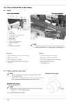
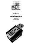
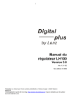
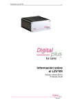
Information
LAN/USB Interface
Art. stno. 23151
1 edition, 10 11
B.10.116
Information LAN/USB Interface 23151
Page 2
Contents
Control elements and displays................................................................ 4
Luminous diodes ..................................................................................... 4
"Reset" button ......................................................................................... 4
XpressNet connection / power supply ................................................... 4
USB connection ........................................................................................ 5
Information on installing and using the software can be found below from
section "Installing the supplied software"............................................... 5
Ethernet (LAN) connection ...................................................................... 5
Connection to a router............................................................................. 6
Direct connection to a PC ....................................................................... 6
IP addressing .......................................................................................... 7
Web Interface ............................................................................................ 7
Windows: ............................................................................................. 7
MacOS X: ............................................................................................ 7
Setting the XpressNet address ............................................................... 9
Installing the supplied software............................................................10
The program "LI-USB Server" ...............................................................13
The program "LI-USB Throttle".............................................................14
The program "LI-USB CV Editor"..........................................................15
The menu "File".....................................................................................16
The menu "Mode" .................................................................................17
The menu "Display"...............................................................................17
The tab "All CVs"...................................................................................17
The tab "General Settings"....................................................................20
Decoder descriptions ............................................................................21
Creating decoder descriptions ..............................................................21
Structure of a description file: ...............................................................23
Information LAN/USB Interface 23151
Page 3
Important advice, please read first!
The Interface 23151 is a component of the Digital plus by Lenz® system
and was submitted to intensive testing before delivery. Lenz Elektronik
GmbH guarantees fault-free operation if you follow the advice below:
The Interface 23151 may be used only with Digital plus by Lenz®
components. Any use other than the one described in this operating
manual is not permitted and all guarantees shall become null and void if
the Interface 23151 is used inappropriately.
Connect your Interface 23151 only to devices which are designed for this
purpose. This operating manual will inform you which devices are
suitable. You must not operate the Interface 23151 with any other devices
(including those of other manufacturers) even if they use the same
connectors. The fact that the connectors are similar does not
automatically mean that you may use them for operation, even if you are
dealing with devices for model railway control.
Do not expose the Interface 23151 to damp or direct sunlight.
Please contact us if you have any questions which this operating manual
does not answer:
Postal
address:
Lenz Elektronik GmbH
Hüttenbergstraße 29
D-35398 Gießen
Phone:
+49 (0) 6403 900 133
Fax:
+49 (0) 6403 900 155
E-mail:
[email protected]
The recorded message will
inform you of times when we
are available.
If you experience any problems with the Interface 23151, please contact
us, providing the following information:
• The devices you are using (LZV100, LZ100, Compact etc.)
• The version number of these devices and your Interface 23151.
Information LAN/USB Interface 23151
Page 4
Control elements and displays
Luminous diodes
Three luminous diodes indicate the operational status of the Interface:
XpressNet (red):
Initialisation complete, device in operation,
XpressNet connected.
Data (yellow):
Flashes during data transmission
XpressNet to or from the Interface.
USB (green):
USB connection established.
on
the
"Reset" button
If this button is pressed and held before start-up (operating voltage fed to
XpressNet connection), all parameters of the device will be reset to
factory settings:
•
The factory firmware will be loaded and all updates deleted.
•
The XpressNet address is set to 22.
•
The device is set to the fixed IP address 192.168.0.200.
Pressing the button during operation has no effect.
XpressNet connection / power supply
The Interface is supplied via the XpressNet connection. To make the
connection, connect the "XpressNet" socket to the command station
LZ100/LZV100.
Use cable 1 included in the package to
connect the XpressNet.
Plug one end into the "XpressNet" socket of
the Interface 23151 and connect the other
end to an adapter LA152.
Information LAN/USB Interface 23151
Page 5
If you want to connect the Interface 23151 to
the terminal screws LMAB of a
LZ100/LZV100 command station, simply cut
the cable in the middle and connect the cable
wires to the corresponding terminal screws.
The pin assignment is shown in the
illustration on the right.
The factory setting of the Interface’s XpressNet address is 22. This setting
can be changed through the Web Interface (see Section "Web Interface")
in the framework of the XpressNet specification.
USB connection
The USB connection can be used in parallel to the LAN connection. The
driver can be found in the directory "USB Driver". When connecting the
Interface to the USB port of the PC, Windows will ask for the location of
the driver. Indicate the directory.
Use the cable included in the package to
connect the Interface to the USB interface.
We recommend that you use the applications delivered with the Interface
for the initial operation since this allows you to verify that the connection to
the XpressNet is correct and that the device functions properly.
Information on installing and using the software can be found below from
section "Installing the supplied software on Page 10 onwards.
Ethernet (LAN) connection
The Interface is equipped with an Ethernet connection for use in a
network. This allows for up to eight simultaneous connections with other
network devices.
Information LAN/USB Interface 23151
Page 6
You need a commercial Ethernet cable to
use the LAN interface.
Which cable you use depends on whether
you want to connect the Interface directly to a
PC or to a router.
Connection to a router
The connection is usually made via a router. If a WLAN router is used, the
Interface can be called via mobile WLAN devices. You can use, for
example, the software "TouchCab" (http://www.touchcab.com/).
Connect the LAN interface of the Interface 23151 with a free LAN
interface of the router.
Direct connection to a PC
A direct connection to a PC is possible with a Xover LAN cable. In this
case, the PC must be set to an IP address in the range of the Interface,
for example 192.168.0.201.
Information LAN/USB Interface 23151
Page 7
IP addressing
The factory setting of the Interface’s IP address is 192.168.0.200.
You may have to set your router to this address range in order to be able
to access the Interface.
The Interface can be set to DHCP operation. Information can be found in
the Section "Web Interface". For practical use, we recommend the use of
a fixed IP address.
The subnet mask is 255.255.255.0.
The TCP port is 5550.
You can change the use of DHCP as well as the set IP as well as the
subnet mask through the Web Interface.
Web Interface
Since the Interface does not have a display, a web server was integrated
in the device. The web server facilitates the displaying and changing of
the IP configuration (DHCP, IP, subnet mask) and the XpressNet address.
The web server also facilitates the uploading of new firmware in the
device.
The device can be found in the network as follows:
Windows:
Enter in the address bar of the browser (Internet Explorer, Firefox etc.):
http://xpressnet
Tests with different routers have shown that calling up "http://xpressnet"
does not always work. In this case, enter the Interface’s IP address in the
address bar of the browser:
http://192.168.0.200
MacOS X:
Use "Collections" in Safari and click "Bonjour". The Interface will be
displayed under "Web pages". Click "Lenz XpressNet Interface".
Information LAN/USB Interface 23151
Page 8
Information LAN/USB Interface 23151
Page 9
Setting the XpressNet address
The Interface has an XpressNet (XBUS) address, just like any other
Digital plus input device. This address is used by the command station to
call up the Interface. The factory setting of the Interface’s address is 22.
If you would like to change the Interface’s address, click the field that
shows the current address. You can change the value via the keyboard.
Please note that you may only enter values between 1 and 31. Moreover,
you may not use an address which is already being used by another
XpressNet device.
When you have set the value, click "Save".
The new setting of the XpressNet address will be saved in the device. The
set XpressNet address will remain unchanged even after the device has
been turned off. However, it can be changed again at any time.
Information LAN/USB Interface 23151
Page 10
Installing the supplied software
Advice:
The software delivered with the product only functions with Windows
XP© and Windows 7© using the USB interface.
1. Insert the supplied CD "Information and software for USB interface"
into the CD-ROM drive.
2. Click "Start" and then "Execute".
3. Enter:
"D:\Anwendungen\LI-USB.msi" and press "Enter"
(Replace "D" with the letter of your CD-ROM drive, as appropriate.)
The program for the installation of the "LI-USB Server", "LI-USB CV
Editor" and "LI-USB Fahrpult" will be started.
Follow the instructions on the screen:
Click "Next".
Information LAN/USB Interface 23151
Page 11
The proposed installation folder is "C:\Programme\LI-USB\". This can be
changed as desired.
Click "Next".
Information LAN/USB Interface 23151
Page 12
The LI-USB applications are now installed on your PC.
Upon successful installation of the applications, this window will pop up.
Click "Close" to exit the installation.
Information LAN/USB Interface 23151
Page 13
Upon successful installation, three new icons will be displayed on your
desktop:
The program "LI-USB Server"
The program "LI-USB Server" provides a TCP/IP server for the other
applications. It ensures secure communication between these
applications and the USB interface. It is automatically started together
with any of the three applications.
If the Interface is correctly connected to
the USB port of your PC and the
Digital plus by Lenz® system is active,
communication between the Interface
and the PC is automatically established.
If the Interface is not connected or the
USB driver is not installed, you will
receive an error message.
In this case, check all connections between the PC and the Interface.
The USB server allows two applications to simultaneously access the
Interface and, therefore, the Digital plus by Lenz ® system. This feature is
particularly useful if you want to use the control panel to test decoder
settings that you have changed with the CV editor.
Information LAN/USB Interface 23151
Page 14
The program "LI-USB Throttle"
This program enables you to control
Digital plus by Lenz ® layout via your PC.
locomotives
on
the
Start the program by double-clicking the icon
"LI-USB Fahrpult" on your desktop.
Once the program has been started (the program "LI-USB Server" is
started automatically at the same time), you will see the program window.
Please refer to the following page for more information.
Click here and enter the desired
locomotive address via your
keyboard.
Use the slider for speed control.
The speed step and speed step
mode are shown above the
slider.
Use these buttons to activate or
deactivate functions. Activated
functions are highlighted.
This button triggers a STOP for
all locomotives. Click and the
locomotives will move again.
These buttons determine the
direction of travel.
Information LAN/USB Interface 23151
Page 15
You may open up to two control panels simultaneously if no other LI-USB
application is running (the USB server does not count!).
Exit the programme via the menu "File" and "End" or by clicking the cross
in the top right corner of the program window.
The program "LI-USB CV Editor"
This program enables you to program locomotive decoders on the
programming track or in operational mode via your PC. While
programming on the programming track, it is possible to read out CV
values.
"Decoder descriptions" ensure that you do not have to remember which
CV is responsible for which feature. These descriptions can be loaded
into the CV editor in which case the CVs and their respective features will
be displayed.
You can also save decoder values. In combination with the decoder
descriptions, you can save the CV settings for each decoder used on your
PC and reload them into the decoder, if required.
Start the program by double-clicking
the icon "LI-USB CV Editor" on your
desktop.
Once the program has been started (the program "LI-USB Server" is
started automatically at the same time), the decoder description "Standard
decoder" is loaded.
Information LAN/USB Interface 23151
Page 16
This window is displayed once the program has been started
The menu "File"
Open decoder description file…
Here, you can select and open a decoder description file.
By default, decoder description files are stored in the folder where
the program files are installed. Unless you have chosen a different
folder during installation, this is "C:\Programme\LI-USB", but you
may also choose any other folder.
Load decoder values…
This command enables you to load a value file for a decoder. This
file contains the CV values. Load the appropriate decoder
description first.
Save decoder values…
This command enables you to save the values which have been
read out of the decoder or entered into the CVs of the decoder in a
file.
Information LAN/USB Interface 23151
Page 17
End Strg+Q
This command terminates the program. Alternatively, you can use
the key combination "Ctrl+Q" or click the cross in the top right
corner of the program window.
The menu "Mode"
Programming on the service track
Programming on the Main
Use these two commands to select the programming mode. It is
impossible to read out CV values when programming in operational
mode.
Finish programming mode automatically
When programming on the programming track, choose this option
to exit the programming mode of the command station after each
read-out or programming procedure.
End programming mode now"
Use this command to exit the programming mode of the command
station if the option "Programmiermodus automatisch beenden"
("Exit programming mode automatically ") is deactivated.
The menu "Display"
Show CV Values in categories
You can view decoder CVs in the program window either by
categories or by the order of the CVs. The decoder description
defines which CVs are displayed in which category.
Show bit values conforming to the Lenz standard
This (default) option displays bits starting with 1. Untick this option
to display bits starting with 0.
The tab "All CVs"
The left side of this tab shows a list of CVs defined in the
respectively loaded decoder description. During initial operation,
the description "Standard decoder" is loaded and displayed; the
CVs are shown by categories. CVs are displayed and used as in
the Windows© Explorer.
Information LAN/USB Interface 23151
Page 18
Click '-' to hide the list of CVs under
the category and keep the overview
simple and clear.
Click a CV to see "All CVs" on the right-hand side of the tab:
Read button
Write button
Value field
Value range
CV description
"Read" button
Click "L" to read out the selected CV (only possible if
"Programmieren auf dem Programmiergleis" ("Programming on
the programming track") is selected in the menu "Modus"
("Mode")). The read-out value will be displayed in the value field.
"Write" button
Click "S" to enter the numerical value shown in the value field
into the respective CV. The program will automatically re-read
the value to ensure that it is correct (if "Programmieren auf dem
Programmiergleis" ("Programming on the programming track") is
Information LAN/USB Interface 23151
Page 19
selected). The program detects and reports errors made when
entering the value. 1
Value field
The value field shows the read-out value of a CV. When loading
a value file, the value contained in the file for this CV will be
displayed. You can change the value by clicking the field and
entering a different value via the keyboard. Click the "S" button
to enter the value in the CV.
Value range
The value range permitted for the selected CV is shown here.
CV description
This text contains information about the decoder features that
can be changed with the selected CV.
1
When resetting a decoder by changing CV8, the manufacturer ID will be re-read during the
following read-out. Of course, this does not correspond to the value which you have entered
for the decoder set. You will receive an error message which you can ignore.
Information LAN/USB Interface 23151
Page 20
At the bottom right of the tab "All CVs", you will find a maximum of
five more buttons:
Read/Write group
Click this button to read/write all CVs of the selected category.
Read/Write all
Click this button to read/write all CVs defined in the decoder
description.
Default= [value]
Click this button to enter the default value stored in the decoder
description into the selected CV.
The tab "General Settings"
Use these buttons to read out and change the decoder features
used most often.
Information LAN/USB Interface 23151
Page 21
Programming the locomotive address is particularly easy here. You
do not have to choose between a 2 or a 4-digit address; simply
enter the address in the address field. The settings of CV1, CV17,
CV18 and CV29 are automatically taken over by the program.
Read / Write curve
Use these buttons to adjust the characteristic speed line.
Click "Read curve" to read out the appropriate values and to
display the resulting speed line graphically.
Use the mouse to edit the speed line (click and draw). The
program automatically calculates the related values. Click "Write
curve" to enter the values in the locomotive decoder.
Decoder descriptions
These decoder descriptions are supplied with the CV editor:
•
"LENZ Gold-Decoder_DE": decoder description for the "GOLD"series decoders
•
"LENZ SILVER_DE.dec": decoder description for the "SILVER"series decoders
•
"Standard_DE.dec": decoder description for the "STANDARD"decoder
"Standard_EN.dec" and "LENZ GOLD_EN
The description "Standard" contains all CVs defined by the NMRA. The
description "Gold decoder" contains all CVs used in these decoders.
Creating decoder descriptions
A decoder description file is a text file that can be edited with any simple
editor. If you want to create your own or edit existing description files,
make sure that the file extension remains "dec" when saving.
It is easiest to use the Windows® program "Notepad" to create or edit
description files.
Information LAN/USB Interface 23151
Page 22
Please do not forget to back up the descriptions supplied with the
product!
Open an existing description file or
create a new file with "Notepad".
Edit the file.
Assign a file name and add the file
extension ".dec"
Make sure that 'Dateityp' ('Files of
type') is set to 'Textdokumente'
('Text documents') when saving the
file.
Advice:
To see the file extension, the box
'Dateinamenerweiterung bei
bekannten Dateitypen ausblenden'
('Hide extensions for known file
types') in the Folder Options of the
Windows® Explorer must be
unchecked!
Description files MUST BE saved in the folder that contains the program
file 'CVEdit.exe'. After installation this is the folder
Programme\LI_USB\CV-Edit. Here, you will also find the description files
supplied with the product.
To picture the structure of a description file, open an existing description
and view its entries.
Information LAN/USB Interface 23151
Page 23
Structure of a description file:
(Explanations in blue)
*****Lenz Gold Decoder
This is the name of the decoder as shown in the heading of the editor.
Syntax 5 stars, then an L for Lenz bit depiction or a blank for other bit
depictions, then the name
+++++0,General CVs / Address
Below are the category names for the depiction of CVs in the program
by category.
Syntax: 5 +, then the category number (0-99), then the category name
+++++2,Motor control
+++++3,Speed parameter
+++++4,Speed characteristic,G
This is the category of CVs that are used to depict the speed
characteristic. This is the only category with a 'G' after the category
name. It may only be assigned to one category!
+++++7,Shunting mode
+++++8,Function mapping
+++++9,Function outputs
+++++12,ABC functions
+++++20,SUSI programming
#####1,1,127,0,0,3,Basic locomotive address
This is the entry for a CV (here CV1), its syntax is shown on the next
page.
Information LAN/USB Interface 23151
Page 24
##### (Isolator)
The CV number (here 1)
The lower value threshold (here 1)
The upper value threshold (here 127)
The flag whether the bit depiction is activated for this
CV (0=active, 1= inactive)
The number of the category to which the CV belongs
(here 0).
Attention: If the category itself (see above) is not
defined, this CV will not be displayed by category.
Default value of the CV
Description. Additional lines with explanatory texts may
follow.
#####
1,1,127 ,0,0,3,Basic locomotive address
Important: Do not forget the commas between the values!
Information LAN/USB Interface 23151
Page 25
All rights reserved. Error and changes due to technical progress, product maintenance or changes in production methods
excepted. We accept no responsibility for direct or indirect damage resulting from improper use, non-observance of
instructions, use of transformers or other electrical equipment which is not authorised for use with model railways or which
has been altered or adapted or which is faulty. Furthermore, we accept no responsibility for damage resulting from
unauthorised modifications to equipment or acts of violence or overheating or effects of moisture etc. In all such cases,
guarantees shall become null and void.
The customer uses the USB interface, the supplied applications and documentation at his or her own risk. Lenz Elektronik
GmbH is not liable for damage caused or incurred by the user or third parties as a result of such use. In no event shall Lenz
Elektronik GmbH be liable for lost sales or profits or the loss of data or direct, indirect, special, logical, accidental or punitive
damages resulting from the use or the inability to use the USB interface, the supplied applications and documentation,
irrespective of any theoretical liability. This is also true if Lenz Elektronik GmbH was informed about the possibility of such
damages.
Reprint or duplication of any kind by permission of Lenz Elektronik GmbH only.
Windows©, Windows XP© and Windows 7© are registered trademarks of Microsoft Corporation.
Acrobat© Reader copyright Adobe Systems Incorporated. All rights reserved. Adobe and Acrobat are trademarks of Adobe
Systems Incorporated and may be registered in certain jurisdictions.
© 2011 Lenz Elektronik GmbH
Hüttenbergstraße 29
D – 35398 Gießen
Tel: 06403 900 133
Fax: 06403 900 155
[email protected]
www.digital-plus.de