Download rev 77 – GB pdf
Transcript
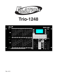
Cerebellum digi -1024
DMX512 Controller
Operating instructions
Keep the document for future reference!
rev.77 – 28/10/2010
DEZELECTRIC
Cerebellum digi 1024
INTRODUCTION................................................................................................................................................................5
INSTALLATION .................................................................................................................................................................5
SOFTWARE UPDATE ......................................................................................................................................................5
HOW TO START ...............................................................................................................................................................6
CONTROL OF THE CHANNELS ...................................................................................................................................6
TEXT EDITING .................................................................................................................................................................6
DATA SAVING ..................................................................................................................................................................7
KEYBOARD LOCK ..........................................................................................................................................................7
MAIN MODE .......................................................................................................................................................................7
ENTER INTO THE MENU...............................................................................................................................................7
UNIT SELECTION ............................................................................................................................................................7
UNIT GROUPING .............................................................................................................................................................8
CHANGING THE CHANNEL VALUE...........................................................................................................................8
SAVING THE PROGRAM IMAGE ................................................................................................................................8
PROGRAM RUNNING .....................................................................................................................................................8
MAKING THE PALETTE ................................................................................................................................................9
USE OF THE MACROS....................................................................................................................................................9
USE OF THE SHAPES ......................................................................................................................................................9
SAVING THE SHAPES................................................................................................................................................... 10
STARTING THE SHAPES.............................................................................................................................................. 11
CHANNEL DIRECTION ................................................................................................................................................ 11
PRESENTATION OF THE CONTROLS ...................................................................................................................... 11
MENU ................................................................................................................................................................................ 11
SHIFT ................................................................................................................................................................................ 11
BLACK-OUT .................................................................................................................................................................... 11
FREEZ............................................................................................................................................................................... 12
DEFAULT ......................................................................................................................................................................... 12
POSITION......................................................................................................................................................................... 12
GRAND-MASTER POTENTIOMETER....................................................................................................................... 12
MODE SELECTION BUTTONS FOR BUTTONS 1-24 (MACRO, PALETTE, FIXTURE, GROUP) .................. 12
MODE SELECTING BUTTONS FOR REGISTER POTENTIOMETERS (RATE, WAIT, DELAY, DIMMER)12
EFFECT SELECTING BUTTONS (1-12, PAN,TILT,…,EFFECT3) ......................................................................... 13
JOG WHEELS (W1,W2,W3,W4) ................................................................................................................................... 13
NUMERIC KEYPAD....................................................................................................................................................... 13
REGISTER POTENTIOMETERS (1-12) ...................................................................................................................... 13
REGISTER BUTTONS (1-12)......................................................................................................................................... 14
REGISTER PAGE SHIFTING BUTTONS (UP, DOWN) ........................................................................................... 14
REGISTER SELECTING BUTTONS (1-12 BLUE)..................................................................................................... 14
[email protected]
2
www.dezelectric.hu
DEZELECTRIC
Cerebellum digi1024
MUSIC (BLUE) ................................................................................................................................................................ 14
BPM (BLUE)..................................................................................................................................................................... 15
STOP (BLUE) ................................................................................................................................................................... 15
STEP (BLUE).................................................................................................................................................................... 15
SYNC (BLUE)................................................................................................................................................................... 15
POTI-1-24.......................................................................................................................................................................... 15
CLEAR .............................................................................................................................................................................. 17
OFF .................................................................................................................................................................................... 17
RECORD........................................................................................................................................................................... 17
DELETE ............................................................................................................................................................................ 17
RECALL............................................................................................................................................................................ 18
MODIFY............................................................................................................................................................................ 18
MOVE................................................................................................................................................................................ 18
SHAPE............................................................................................................................................................................... 18
SHOW................................................................................................................................................................................ 18
FADE ................................................................................................................................................................................. 19
LIGHT O. .......................................................................................................................................................................... 19
SCREEN ............................................................................................................................................................................ 20
MONITOR ........................................................................................................................................................................ 20
MENU SYSTEM ............................................................................................................................................................... 22
STRUCTURE OF THE MENU....................................................................................................................................... 22
MENU – DMX ADDRESSING........................................................................................................................................ 22
MENU – UNIT LIBRARY ................................................................................................................................................ 23
MANUFACTURERS’ LIST ............................................................................................................................................ 23
UNIT LIST ........................................................................................................................................................................ 23
FIXTURE DELETE ......................................................................................................................................................... 24
ENTERING A NEW UNIT.............................................................................................................................................. 24
MENU - CUSTOMIZATION............................................................................................................................................ 25
SHIFT-BUTTON .............................................................................................................................................................. 25
FIXTURE SELECTION .................................................................................................................................................. 25
REG POTI LINK SYNC.................................................................................................................................................. 26
LANGUAGE SELECTION ............................................................................................................................................. 26
DISPLAY........................................................................................................................................................................... 26
LED ADJUSTMENT........................................................................................................................................................ 26
DATE, TIME .................................................................................................................................................................... 26
WIPE-ALL ........................................................................................................................................................................ 27
MENU - INFORMATION................................................................................................................................................. 27
UPTIME ............................................................................................................................................................................ 27
SOFTWARE VERSION .................................................................................................................................................. 27
DATE OF ISSUE OF THE SOFTWARE ...................................................................................................................... 27
www.dezelectric.hu
3
[email protected]
DEZELECTRIC
Cerebellum digi 1024
SERIAL NUMBER........................................................................................................................................................... 27
MANUFACTURING DATE............................................................................................................................................ 27
MENÜ - PENDRIVE......................................................................................................................................................... 27
DATA FROM PENDRIVE TO CONTROLLER .......................................................................................................... 27
DATA FROM CONTROLLER TO PENDRIVE .......................................................................................................... 27
TECHNICAL DATA ......................................................................................................................................................... 29
CONNECTORS AND THEIR LINKING........................................................................................................................ 29
DIMENSIONS AND WEIGHT ........................................................................................................................................ 29
ACCESSORIES ............................................................................................................................................................... 29
[email protected]
4
www.dezelectric.hu
DEZELECTRIC
Cerebellum digi1024
INTRODUCTION
For the control of universal “live” light control panel scanners, moving heads, PAR lights. In comparison with the
former DEZTELECTRIC light controllers it is a new feature thereof that a monitor, mouse and keyboard can be
connected, the enlarged user interface is larger than the standard rack size. It has an USB connection possibility for the
software updating via the PC and data copying, and at the same time an USB pendrive can be directly connected as well.
For the use of the controller it is essential to read through the operating instructions and simultaneously operate the
controller. If you have any question, contact the factory or the dealer by e-mail. Here you can report the possible
remarks and recommendations experienced by you. We answer your questions by e-mail or upload the software
developed by you, from where you can download or install the newer version, since the software of the controller can be
updated free of charge. If you would like to find out the freshness of the software of your controller, enter the menu,
select the menu item INFORMATION. Upon logging on the version number of the software of the controller and the
date of placing on the market can be read in the display. Compare the version number with the software version number
that can be found in the website of the manufacturer or the dealer, and if necessary, update the controller software by
means of those described in the SOFTWARE UPDATE section.
INSTALLATION
After connecting the network cable, upon turning on the mains switch the LEDs of the controller are switched on, and
the logon text can be seen in the display for some seconds, and then the controller goes to a mode ready for immediate
action.
If after turning on the caption „SZOFTVER FRISSÍTÉS SZÜKSÉGES” (“Software update required”) is shown in the
display, the controller will be usable only after updating the software.
It may occur if the connection is cut off during the software update or power failure takes place, so the update is
interrupted.
Turning off the appliance: in any mode it is possible by turning off the mains switch.
Five stages of the LEDs in the switches of the controller are distinguished, the knowledge of which facilitates the
operation of the controller.
- it does not illuminate: At this time the related switch does not have any function in the current mode, there is no
consequence of pressing it
- it illuminates with half intensity: It indicates that the related switch has some function, and it can be activated by
pressing the button.
- it illuminates with full intensity: The function of the button related to the LED is active, which can be turned off by
pressing another button, not by itself.
- it flashes with full intensity: it indicates such a powered-up function, which can be turned off by pressing the button
related to the LED.
- it flashes with half intensity: it indicates such an activated function, in which a parameter has already been modified,
but at present it is not the current mode. By pressing the related LED the function of the button related to the LED
becomes active again, its LED flashes with full intensity.
SOFTWARE UPDATE
Use of the downloading software: ATTENTION! The software runs only under Windows operating systems.
Follow those listed in the points listed below from step to step for completing the software update:
1.
You will be required for the software update:
a. Besides the controller a computer, in which the Windows operating systems is running and there is a
connection possibility of an USB port.
b. A standard USB cable, with which the controller and the computer must be connected.
c. Downloading software, which is available in the homepage of the controller distributor or
manufacturer, its name is ’Ldm.exe’.
d. Updating file, which includes the software to be loaded into the controller, its name is e.g.:
’Cer1024v20.dat’. In the file name the last two digits refer to the software version number. It can also
be found in the homepage of the manufacturer or distributor.
www.dezelectric.hu
5
[email protected]
DEZELECTRIC
Cerebellum digi 1024
2.
3.
4.
5.
6.
7.
Connect the controller and the computer with the cable.
Connect the controller to the power supply.
Start the downloading software in the computer (’Ldm.exe’).
The software automatically starts making a connection.
If the setup and connection are all right, the data of the controller are shown in the window (type, etc.).
In case of a correct connection click on the Downloading icon (Icon 1) or select the File/Open menu item, and
find the file to be loaded into the controller (e.g..: Cer1024v20.dat), and then acknowledge the selection with
the “Open” button.
8. Click on the Download button, and the downloading starts.
9. The stage of the downloading can be monitored in the pop-up process indicator.
10. If the process is competed, the update is ready. For disconnection only pull out the USB cable from the
controller.
11. If during the update any fault, e.g. power failure should occur, restart the controller by interrupting the power,
and restart the updating software, and repeat the actions.
HOW TO START
CONTROL OF THE CHANNELS
After turning on the controller goes into an automatic mode. For making a SHOW and running them in your own light
equipment, some setups have to be made, i.e. the controller has to be configured. It is recommended to configure the
controller in the following sequence:
- Check the version number of the controller software, if you find a more up-to-date in the homepage of the
distributor or the manufacturer, download it and update the controller, see Chapter SOFTWARE VERSION,
Chapter SOFTWARE UPDATE
- Select the language in which the controller will output the texts in the display, see Chapter LANGUAGE
SELECTION.
- Adjust the contract and brightness of the display if e.g. it illuminates too intensively or outputs the texts palely, see
Chapter DISPLAY SETUP.
- Adjust the intensity of the LEDs to the desired value, see Chapter LED SETUP.
- If the unit to be controlled is not in the unit library, create it, see Chapter UNIT INSTALLATION.
- Configure the units to be controlled, see Chapter DMX PATCH.
- Try out if the adjusted units work properly, see Chapter MANUAL MODE. Take care at what value the
GRAND MASTER potentiometer is in the manual mode!
After making the settings if we are able to set the channels of the units in the manual mode, we are prepared for the use
of the controller. The operation of the controller can be divided into two large parts: AUTOMATIC MODE and
MENU SYSTEM. All modifications and settings can be made in the MENU. In the AUTOMATIC MODE the
recorded events can be run, all effects can be started, which have been set up in the MENU.
TEXT EDITING
In the menu of the controller some names, texts can be given, modified at several places. These can always be modified
in accordance with the same system.
The buttons that can be used for the text editing and their function:
W1
W2
W3
W4
12th button
UP-DOWN
-
selection of a capital letter (A-Z)
selection of a small letter (a-z)
number (0-9)
cursor position
SPACE character insertion
Selects from all characters
Reference can be found to this section in the operating instructions several times.
[email protected]
6
www.dezelectric.hu
DEZELECTRIC
Cerebellum digi1024
DATA SAVING
In the menu item if after the modification of any data we exit the menu item, the controller asks saving of the
modification. Its operation is made in the same way in each menu item.
EXIT - exit without saving the modifications
UP-DOWN - remains in the editing
ENTER - saving the modifications, and then exit to the menu
KEYBOARD LOCK
The controller can be locked by activating the keyboard lock. If this is activated, the programs, effects running and
working, but the switches, sliders, jog wheels have no effects. It can be useful if the user goes away from the desk and
unauthorized persons can not make any changes on the desk.
Activating
SHIFT + MENU
Unactivating:
1. and 12. blue buttons must be press and hol under app. 3sec.
MAIN MODE
After turning on the controller the controller gets into the MAIN mode. Here the written programs, images can be called,
started, their parameters can be set.
ENTER INTO THE MENU
In the MAIN mode you can enter the menu by pressing the MENU button.
UNIT SELECTION
For being able to control a unit, you have to be able to select them. It can be done with buttons 1-24 if the FIXTURE is
active from among the related group-selecting buttons.
If the LED of the FIXTURE button illuminated only with half intensity, press it. At this time its LED will illuminated
with full intensity and units can be selected in buttons 1-24. No unit is assigned to the button from among buttons 1-24,
which does not illuminate. If one is pressed from among them, its LED will flash indicating that the unit is selected.
Upon repressing it its selection will be discontinued.
If we have more than 24 units, you can shift to the next 24 pc units by pressing the FIXTURE button several times. It
can be read in the upper line of the display the units with which serial number can be selected with buttons 1-24.
Multi selection of units
If you want to select more fixtures, you can do it by pressing the first and last one. In this case all fixture will be selected
between the two winger .
Example:
If you want to select the first 10 fixture, press together the 1. and 10., and all also fixtures from 2 to 9 will be selected.
Unit selection with auto deselecting:
You can use this mode if you switch it on in CUSTOMIZE – FIXTURE SELECTION menu. In this mode if you select
one or more fixture and modify by jog wheels any channels of it, and you select other fixture, then the previous fixture
selection will be automatically cleared.
Example:
It is very useful if you want to select different colours for more fixtures. Select first fixture and select a colour by jog.
Select other fixture (you don’t have to deselect the previous one because it will automatically deselect) and select other
colour by jog, ect.
www.dezelectric.hu
7
[email protected]
DEZELECTRIC
Cerebellum digi 1024
UNIT GROUPING
It is possible to simplify the selections in case of the management of many units. Any controlled units can be
coordinated into groups.
Making a group:
- After pressing the FIXTURE button select from among the units in accordance with those described in Chapter
UNIT SELECTION.
- Press the RECORD button.
- Press the GROUP button (it is located to the right from the FIXTURE button).
- Press any of buttons 1-24.
- Saving of the group is finished.
Activation of the group:
- After pressing the GROUP button press any button from buttons 1-24, the LED of which illuminates. The Led’s of
only those buttons illuminate, to where a group has been made.
Tip:
Select all the units in FIXTURE mode, and then save it to button GROUP 24. Discontinue the selection of each unit in
FIXTURE mode, and then save it to button GROUP 23. Result: switching to GROUP mode each unit is activated by
pressing button 24, while the selection of each unit is discontinues by pressing 23.
CHANGING THE CHANNEL VALUE
There are more possibility to set or change dmx channel values.
The channel value of those units can be modified with the JOG discs, which are selected in FIXTURE or FIXTURE
GROUP mode. The name of the channels of the unit selected last can be read in the lower line of the display. The
channels of a unit can be saved to button 12 EFFECT as described in the unit installation, and 4 JOG discs belong to
each EFFECT button. The four channels assigned to the button that is pressed from buttons 1-12 EFFECT can be seen
in the lower line of the display and can be set with the JOG discs. The moved channels automatically get into the
manual and programmer memories as well.
You can order dmx channels to 1-24 sliders. More information: PRESENTATION OF CONTROLLS – POTI 1-24
You can set dmx values by using numeric keypad. More informations: PRESENTATION OF CONTROLLS –
NUMERIC KEYPAD
SAVING THE PROGRAM IMAGE
In the controller the program images can be saved into 12 registers, and each register has 10 turnable pages, so the
images can be saved altogether to 12x10=120 memory locations. Maximum 90 images can be saved to each memory
location, and you can manage from altogether 2,048 memory locations.
A program image consists of the mask of the selected channels and the values of the channels.
The mask of a program image channel (i.e. which channels are included) will be always the state of the programmer
memory upon saving the image. Those channels are included in the programmer memory, which have been modified
with the JOG disc. The programmer memory can be deleted with the OFF button. If you want to completely empty the
programmer memory, press the SHIFT-OFF button. Without SHIFT only the channels of the JOG discs related to the
current EFFECT button will be deleted from the programmer memory.
Saving a program image:
- Select the units in the FIXTURE or FIXTURE GROUP mode.
- Adjust the wanted image by means of the EFFECT buttons and JOG discs. (If meanwhile such a channel is
modified, which you do not want to save into the channel, remember to delete it from the programmer memory.)
- Press the RECORD button.
- Press any of the register buttons 1-12, to which your would like to save the image. Before select the page with the
PAGE UP-DOWN buttons.
More images can be saved to a page of one register, these will be played by the controller after each other.
PROGRAM RUNNING
The images saved into the registers can be called by pressing the REGISTER buttons, or if more images have been
saved, their playing can be started. At least one program image is saved to those REGISTER buttons, the LED of which
[email protected]
8
www.dezelectric.hu
DEZELECTRIC
Cerebellum digi1024
illuminates with half intensity. Upon repressing the button the program running is stopped. In the display always the
data of the program started last, while in the monitor in the MAIN window all the 12 registers can be seen
simultaneously.
Types of shifting between the program images:
A program can shift it images in several ways:
- in accordance with the time set with the WAIT potentiometer
- in accordance with the bass beat of the music for the MUSIC button
- in accordance with the beat entered to the BPM button manually
- upon pressing the STEP button by images
MAKING THE PALETTE
If a channel setting (gobs, colours, effects, etc.) is used frequently, they are worth being saved into the palette.
Example: Several kinds of units are used, and it is often necessary to adjust the red colour. At this time the red value of
the COLOR channel of each unit – that can be different by light types – can be saved into a PALETTE memory, and it
can be called in by pressing a button from here later on. The values of more channels can be hold together as well into a
palette, so e.g. the frequently used blue-star combination can also be saved. Of course, all these apply to the positions of
the mirror or head.
- Delete the programmer memory with the CLEAR button.
- Select units in FIXTURE, or FIXTRURE GROUP mode.
- Move and adjust the channel to the desired value, which you want to save into palette.
- Press the RECORD, and then the PALETTE button.
- Select one from buttons 1-24, where you want to save the palette to, and press it.
- Delete the programmer memory.
- Turn off the selected units, and select the other types.
- Set the channels to the desired value.
- Press the RECORD, and then the PALETTE button.
- Save the settings to the button saved previously.
Tip:
The palette can be used in such a way that different values can also be saved to the same channels of units of same type,
so for example, the colours of the rainbow can be adjusted to 6 uniform units, and it can be saved to a palette.
Afterwards the rainbow can be called in by pressing a button.
With help of LDM software it can be save for personality files palette values. Tih values can be add to palette memory
after making DMX PATCH.
USE OF THE MACROS
Among macros at the moment the flash macros can be setup. In flash-macro mode the selected channels can be flashed
at saved values until the button is pressed.
Example: There are some PAR lamps or dimmer channels of scanners. These must be saved in a flash macro with
maximal values. Later pressing flash buttons this dimmer channels will be lit at maximum values.
-
Delete the programmer memory with the CLEAR button.
Select units in FIXTURE, or FIXTRURE GROUP mode.
Move and adjust the channel to the desired value, which you want to save into macro.
Press the RECORD, and then the MACRO button.
Select one from buttons 1-24, where you want to save the macro to, and press it.
USE OF THE SHAPES
The complicated movement effects can be simply and quickly made by means of the shape generator built into the
control.
The shapes affecting the head movement are PAN, TILT, KÖR (ROUND), NYOLCAS (OCTAD), NÉGYSZÖG
(RECTANGLE), HOMOKÓRA (SAND CLOCK), HÁROMSZÖG (TRIANGLE), and EGYENES (STRAIGHT). A
www.dezelectric.hu
9
[email protected]
DEZELECTRIC
Cerebellum digi 1024
precondition of the use of the shapes is that the channel executing the pan movement is checked to PAN function, and
the one performing the tilt movement is checked to the TILT function in the installation of the unit. See MENU-UNIT
LIBRARY.
The shape mode of the control is turned on by pressing the SHAPE button related to the lower right button group. At
this time its LED will illuminate with full intensity.
In Shape mode the shapes can be selected on buttons 1-24, and with the JOG discs the parameters of the shape can be
adjusted.
-
Select the units in FIXTURE, or FIXTRURE GROUP mode.
Press the SHAPE button.
Select a shape on buttons 1-24: 1-PAN, 2-TILT, 3-KÖR, 4-NYOLCAS, 5-NÉGYSZÖG, 6-HOMOKÓRA, 7HÁROMSZÖG, 8-EGYENES
With 1. JOG disc the speed of the shape can be adjusted
With 2. JOG disc the extension, size of the shape can be adjusted
With 3. JOG disc the offset between the shape units can be adjusted
To turn off the shape press the SHAPE button.
PAN shape:
It is enforced in the PAN channels of the units, the value of the PAN channel changes upwards and downwards with the
given speed and extension compared to its current position. .
TILT shape:
It corresponds with the operation of the PAN shape with the difference that it affects the TILT channel.
KÖR (ROUND), NYOLCAS (OCTAD), NÉGYSZÖG (RECTANGLE), HOMOKÓRA (SAND CLOCK),
HÁROMSZÖG (TRIANGLE), and EGYENES (STRAIGHT) shape
It performs the movement in the PAN and TILT channels of the units as per its specification.
JOG 1 – Speed
The speed of the shapes can be adjusted, the movement of the shape can be accelerated or decelerated.
JOG 2 – Extension:
The shape is implemented around the current position of the unit, the extent of the deviation can be adjusted here.
JOG 3 – Offset:
In case of several units it can be interpreted. If more units are checked and a shape is run on it, it can be given with
offset that by how much a unit should be delayed in the movement compared to the previous one.
JOG 4 – Direction:
The direction of drawing shapes can be set (clock wise or anti clock wise)
Tip:
Shapes can be started for such units that are running in a program, and change their placed on their effect. At this time
the shape started on it is placed onto the movement in the program. So it can be a program moving to the right-left, and
the joint effect of a TILT shape is a zigzag movement on the stage, which can be varied easily by adjusting the
parameters of the shape. .
SAVING THE SHAPES
The switched on shape can be saved and called in later on. The shapes can be saved on the register buttons, altogether
12 buttons = 120 shapes. In each register one shape can be started from among the 10 pages, so altogether 12 shapes can
run simultaneously.
-
Start a shape in accordance with those described in the section USE OF SHAPES.
Set the parameters with the JOGF discs.
Press the RECORD button.
[email protected]
10
www.dezelectric.hu
DEZELECTRIC
Cerebellum digi1024
-
Press any of the register buttons 1-12 in that page, onto which you want to save (the shape can be saved only to
such a button that has been empty so far!).
The program automatically gives a ‘SHAPE + serial number’ name to the saved shape, which can be overwritten later
on.
STARTING THE SHAPES
The shapes saved onto the register buttons can be started by pressing the buttons. A shape can run simultaneously in all
registers next to each other. The shapes saved into the same register, but to a different page replace each other. If a unit
is included in the shape of more registers, it will always start in the one started last..
The parameters of the shapes started in the register buttons can be adjusted with the JOG discs. For this the blue button
of the registers shall be turned on, and the shape mode shall be turned on by pressing the SHAPE button. If more blue
buttons are activated, the parameter of the shape related to each will change.
CHANNEL DIRECTION
It is possible to control every channels in opposite direction.
Select on monitor the 2. window (FIXTRUE): SCREEN + NUM 2
Click by mouse to EFF12 button
Select the direction view by pressing SHIFT + EDIT1 (main function is LIGHT.O this button)
If a channel has normal direction then its letter is N, like Normal. If a channel is reversed, then its letter is R, like
reversed.
Select fixtures which has channel and you like to reverse.
Modify channel value for channel which you like to reverse. The mixer automatically goes back to Auto/Manual
viewing, and the modified channel direction will be reversed.
Saving channel direction settings to memory:
-
Press RECORD button
Press and hold pressed SHIFT button
Press EDIT1 button (higher function of LIGHT O. button)
Release SHIFT button
After saving changes the mixer by next time will automatically load the saved setting.
PRESENTATION OF THE CONTROLS
MENU
By pressing it you can enter the menu.
SHIFT
By pressing the SHIFT the secondary functions of the buttons will be accessible. The secondary functions usually mean
the caption framed above the button.
BLACK-OUT
By pressing it the function can be turned on or off. Those channels that have been given BLACK-OUT selection in the
unit installation, will appear in the DMX outputs with their closed values until they are not switched off by pressing the
BLACK-OUT button again,
www.dezelectric.hu
11
[email protected]
DEZELECTRIC
Cerebellum digi 1024
FREEZ
By pressing it the FREEZ function is turned on, by pressing it again it is turned off. On its effect the image shift of the
running programs discontinues, the currently changing channel values are spragged in the output. By pressing it again
the movements continue.
DEFAULT
By pressing it the channel of all the selected lights is set to the so-called default value. This value is included in the
installation of the units, it is usually a resting value, where the channel does not rotate, move, make effects. In case of
mirrors, rotating heads it means adjustment to the middle and a closed state of the shutter channels.
After turning on the controller each channel gets into this default state.
SHIFT-DEFAULT
By pressing it only the channels of the selected units are loaded as the default values, not for all the units.
POSITION
By means thereof the position of the unit can be established in the stage. Upon pressing it from among the channels of
the selected lights those that have been selected in the installation of the unit as ‘position’ will load their position value
set there. It usually means 100% in case of the dimmer channel, and the strobing value in case of the shutter.
By press and hold pressed the SHIFT button all the fixtures will go to this working modes. So it is possible to check
immediately if all the connected fixtures are well configured.
Example:
Select light 10, and then press the POSITION button. While the button is hold pressed, the light 10 indicates its position
by strobing.
GRAND-MASTER POTENTIOMETER
By its adjustment the master intensity of the controller can be adjusted between 0-100%. Those channels, in the unit
installation of which they have been given DIMMER selection, appear in the rate of the master intensity in the DMX
output.
A unit may have more channels for the GRAND MASTER, e.g. in case of an RGB light all the three colour channels, or
in case of a dimmerpack driving the PARs all of them.
MODE SELECTION BUTTONS FOR BUTTONS 1-24 (MACRO, PALETTE, FIXTURE, GROUP)
The LED of any of the four buttons illuminated with full intensity all the time, it indicates that the buttons 1-24 located
above them are in which mode. By pressing the activated group-selecting buttons (their LED illuminates with full
intensity) again you can scroll the properties accessible in buttons 1-24.
In FIXTURE mode 25-48 units can be selected by pressing the FIXTURE button again. The buttons 1-24 related to the
FIXTURE button have always so many pages as many times 24 units have been assigned to the DMX channels in the
DMX PATH menu. If you have less than 25 units, it cannot be turned, if the number of the controlled units is between
25-48, the FIXTURE button has 2 pages, and it switches back to the first page from the second page by pressing it
again, i.e. units 1-24 will be accessible.
The GROUP mode has two pages, i.e altogether 48 FIXTURE GROUPS can be made. You can read more about making
the groups in Chapter UNIT GROUPING.
The PALLETTE has two pages, so altogether 48 palettes can be selected. You can read more about making the palettes
in Chapter MAKING PALETTE.
The MACRO has one page, so altogether 24 macros can be selected. You can read more about making the macros in
Chapter MAKING MACROS.
MODE SELECTING BUTTONS FOR REGISTER POTENTIOMETERS (RATE, WAIT, DELAY, DIMMER)
The LED of any of the four buttons illuminates with full intensity all the time, it indicates what data can be set with the
potentiometers of the registers. By pressing the WAIT and RATE buttons simultaneously both modes can be set with
the potentiometer simultaneously.
In RATE mode the floating time of the SOFT channels running in the registers can be set. Upon loading an image the
soft channels reach their loaded value from their current value during the set time.
[email protected]
12
www.dezelectric.hu
DEZELECTRIC
Cerebellum digi1024
In WAIT mode the image-shifting time of the registers can be set. After the expiry of the set time the register loads the
next assigned image.
In Dimmer mode the value of dimmer channels can be controlled. If ther is a running program in a register and there is
also dimmer channels among program mask, then this channels can be controller by dimmers.
In Delay mode you can call a special effect. If delay value is 0, then there is no effect. If delay value greater then 0 than
after scene change not all channel will be load in actual scene but the first one. After scene change time will be load the
next channel, and so on.
Example: make a program with two scene. Both of them can be included only color channels. First scene set to green,
and second scene set to red. Run this program. Set delay to one. Now on every program scene changing only one
scanner color will change.
EFFECT SELECTING BUTTONS (1-12, PAN,TILT,…,EFFECT3)
A unit can have maximum 48 channels. Their values can be set with the JOG discs. In order to reach all the 48 channels
with 4 JOG discs, selecting buttons are needed. By means of the 12 EFFECT selecting buttons all the 48 channels
become accessible: 12x4=48.
The LED of one button from among the 12 buttons always illuminates with full intensity, it will be the selected one.
Always the 4 channels related to the selected button can be controlled with the JOG discs. The assignment of the
EFFECT button can be set or reconfigured in the installation of the unit.
It can be read in the lower line of the display what channels can be controlled with the 4 JOG discs related to the
currently selected EFFECT button. If the lower columns are empty, it means that no unit is selected, so no adjustment is
needed.
The effect captions located above the EFFECT buttons (PAN,TILT,DIMMER…SPEED,…,etc.) are only for
information, but it is worth configuring these units, and they can be easily identified at that time, and the channels can
be accessed fast.
JOG WHEELS (W1,W2,W3,W4)
The channels of the selected units can be set primarily with the JOG discs. Always the four channels related to the
current EFFECT button can be set with the JOG discs. The channels moved with the JOG disc get into the manual and
the programmer memories.
NUMERIC KEYPAD
The dmx channel values can be set or modify by using the numeric keypad
Set channels values to maximum value (255):
• Type a DMX address between 1 and 1024
• Press ENTER
• The typed DMX channel value will set to 255
Set channel values to all range (0-255)
• Select fixtures by 1-24 button
• Select effect group by 1-12 effect button
• Type a JOG number (1-4) by numeric keypad
• Press TAB button on numeric keypad (arrow to right)
• Type channel value between 1-255
• Press ENTER button
• The selected channel will get the typed value
REGISTER POTENTIOMETERS (1-12)
With the REGISTER POTENTIOMETER some parameters of the 12 registers managed by the controller can be set.
One is always active from among the mode selecting buttons (RATE, WAIT, DELAY, DIMMER) related to the register
potentiometers, and the parameter related to the one that illuminates with full intensity can be set with the
potentiometers.
WAIT adjustment:
www.dezelectric.hu
13
[email protected]
DEZELECTRIC
Cerebellum digi 1024
By switching to WAIT mode the scene shifting time of the registers can be set between 0.10s -35-0s with the
potentiometers.
RATE adjustment:
By switching to RATE mode the floating time of the soft channels included in the registers can be set between 0.10s 35.0s.
DELAY adjustment:
By switching to DEALY mode, then it is possible to run a program by channels. If the value is ALL then there is no
shifting between channels loading time. If the value is between 1 and 10, then the selected number of channels will be
load after starting program and after every wait time will load the next couple of channels. If all channels which are in
the actual program scene is loaded then after next period will activated the next scene.
Example: If we make a program with two scenes, and every scene has only PAN-TILT channels (16bit each, so four
channels) with different positions, then after starting program and with DELAY mode value 4 the first projector will
move first, and then the other. Then will load next scene.
DIMMER adjustment:
If in a register we have running program then all channel value which are DIMMER type can be regulated with this
DIMMER slider value. It works as register master fader.
The four modes (RATE, WAIT, DELAY, DIMMER) can be attach to 1-24 sliders. (more information about attaching in
1-14 Slider part)
REGISTER BUTTONS (1-12)
With REGISTER BUTTONS the programs can be started or stopped in the 12 registers managed by the controller. All
the 12 registers have 10 pages (PAGE), on all of which a program can be saved, respectively. Always the program of the
current page can be started. If any of the LEDs illuminates with little intensity, it indicates that there is a program image
saved in the current page of the register. By pressing the button the LED starts flashing, and the program saved on it
starts running. By pressing the button again the program running is stopped. If a program is started in one page, the
program having run so far stops, and only the newly started one will run. The programs located in the pages of one
register substitute each other, while the programs can be run in the different registers simultaneously.
By holding the SHIFT button pressed the data of the register related to the pressed buttons are shown in the display,
while in the monitor the data of all the 12 registers can be seen simultaneously.
REGISTER PAGE SHIFTING BUTTONS (UP, DOWN)
All the registers have 10 pages, on all of which programs can be saved. 12 registers x 10 pages = 120 programs. between
the pages you can shift with the PAGE UP-DOWN buttons. The number of the current page can be read in the seven
segment display next to it.
REGISTER SELECTING BUTTONS (1-12 BLUE)
With the register group buttons (blue coloured: MUSIC, BPM, STOP, STEP) different running modes can be selected in
the registers. In order that the controller knows in which registers the activated event has to be executed from 12, the
registers have to be selected with these 12 blue buttons.
If the LED of the button illuminates with little intensity, the group is not selected, if the button is pressed, its LED starts
flashing, the group will be selected. By pressing it again the selection is ceased.
More registers can be selected simultaneously, if one of them is pressed and then another one is pressed in addition, all
those located between them switch to its state pressed at first.
MUSIC (BLUE)
The beats sensed by the controller can be monitored in the LED of the MUSIC button. By pressing the MUSIC button
the selected registers (blue buttons 1-12 with flashing LED) get into music mode. The programs of the registers started
in music mode the images are shifted in accordance with the beat of the purchased music.
From music mode we can go over by selecting another mode (e.g. STEP) or moving the WAIT potentiometer of the
register.
[email protected]
14
www.dezelectric.hu
DEZELECTRIC
Cerebellum digi1024
Microphone sensitivity can be set! On the MAIN window on Monitor screen you can see the actual value of microphone
sensitivity. Hold the MUSIC button, and by first JOG wheel you can set the sensitivity.
BPM (BLUE)
When striking the BPM button according to the music rhythm severally, the controller remembers the struck pace and it
will set the scene shifting according to it. The bpm value of the given pace can be read on the display. This setup also
works only in the selected registers (where blue LED is blinking). It can be switched off by giving a new wait value or
auto bpm.
STOP (BLUE)
By pressing the STOP button the selected registers get into stop mode, while by pressing the STOP button again the stop
mode of the register is not ceased.
STEP (BLUE)
By pressing the STEP button the selected registers get into step mode, and no image shifting is made until the STEP
button is pressed again. At this time the image saved for them is loaded, and they wait for the next pressing again.
From Step mode you can go over by selecting another mode (e.g.: MUSIC) or by moving the WAIT potentiometer of
the register.
SYNC (BLUE)
By pressing the SYNC button the WAIT time of the selected registers are synchronized to each other. Always the
image-shifting and floating time of the first register selected from the left will be set into the other registers. However, it
is possible to synchronize the selected registers with the data of any register. For this the SYNC button has to be hold
pressed, and meanwhile the selecting button (1-12 blue) of any register has to be pressed. On its effect the WAIT and
RATE value of all the selected registers (thee LED of the blue button flashes) is set to the value of the pressed register,
it is either selected or not.
SHIFT-SYNC (LINK)
Upon pressing it the registers selected next to each other are linked to each other. On its effect the program started in
any of the linked registers turn off the program running in the other registers linked to it, i.e. if fewer programs are used,
they do not have to write them to a separate page, they are able to replace each other, written to one page.
The links cease if no register is selected in the blue buttons 1-12 upon pressing the SHIFT-SYNC.
POTI-1-24
For the upper 1-24 potentiometers there is a possibility to assign any channel of any unit, either more channels of more
units at the same time, either all of them. So the channels can be set in any grouping directly. And also possible to get
minimum and maximum value for every channel. By moving the slider the channel values will be change only between
minimum and maximum parameters.
ASSIGNMENT OF THE CHANNELS TO SLIDER 1-24
-
Select the unit or units.
Press the button from among 1-12 EFFECT buttons to which that JOG disc is related, to which the channels to be
assigned to potentiometer 1-24 has been assigned.
Move the JOG disc of the channel so that the channel gets into the programmer memory, and set values to
maximum after wish.
Press the RECORD button. (it will be maximum values)
Move that potentiometer from among 1-24, to which the selected channels are to be assigned.
Move the JOG disc of the channel so that the channel gets into the programmer memory, and set values to
minimum after wish.
Press the RECORD button. (it will be minimum values)
Move that potentiometer from among 1-24, to which the selected channels are to be assigned.
www.dezelectric.hu
15
[email protected]
DEZELECTRIC
Cerebellum digi 1024
Afterwards the value of the channels selected for it can be adjusted by moving the potentiometer. The same channel can
be saved to more potentiometers as well, at this time the channel will take the value of the potentiometer moved last.
Example:
If we have 6 pc RGB lights, the RGB channel of unit 1 can be assigned to potentiometer 1, the RGB channel of the
second unit can be assigned to potentiometer 1, up to potentiometer 6. The R channel of all the six lights can be saved
to the seventh point, the G channel to potentiometer 8, B channel to potentiometer 9.
The result is that white intensity can be adjusted in the channels by units with potentiometers 1-6, while the intensity of
the colour groups can be adjusted with potentiometers 7,8,9.
ASSIGNMENT OF THE FUXTURES TO SLIDER 1-24
For the upper 1-24 potentiometers there is a possibility to assign fixture channels to 1-24 sliders. With this function you
doesn’t need to assign channels one by one, but simply selecting fixture, moving the first slider and the channels will be
assigned to next sliders.
-
Select a fixture or fixtures
Press RECORD button
Press FIXTURE button
Move one slider from 1-24
From the moved slider you can reach all fixture channels. In first positions you can set the first dmx channel of the
actual fixture and in the last position you can set the last dmx channel of the actual selected fixture..
1-24 SLIDER WORKING MODE
Sliders can be program to different working mode:
o
o
Channel control. Sliders can be work in single and master mode
Register parameter adjust (WAIT, SPEED, DELAY, DIMMER)
Channels adjust with 1-24 slider
In single mode the channels value can be modify between minimum and maximum value (LTP mode).
In master mode the slider effects not alone to channels but also together with other master sliders. Always the highest
value will be appear on the output (HTP mode).
The mode of slider you can on monitor in NAME window. Upper slider column you can click the PARAMETER
button. The you will see the slider modes. If you click to any slider mode it will be change to other.
Saving slider mode with buttons:
-
Press RECORD button
Press and HOLD SHIFT button
Press SELECT button
Release SHIFT button
Move the slider which you want to change its parameters
1-24 SLIDER SETTINGS DELETE
The slider parameters can be also delete (minimum, maximum, mode, channel mask). After delet this slider will be no
effect to channel if you move.
[email protected]
16
www.dezelectric.hu
DEZELECTRIC
Cerebellum digi1024
-
Press and HOLD SHIFT button
Press DELETE button (higher function of RECALL button)
Release SHIFT button
Move the slider which you want to delete its parameters
Register parameter adjust with 1-24 slider
It is possible to set register parameters by 1-24 sliders. The 1. register parameters can be adjust by slider 1 and 13. the 2.
register parameter can be adjust by slider 2. and 14. and so on.
Press REDORD button
Select a parameter (pushing SPEED, WAIT, DELAY or DIMMER)
Move one slider from 1-24 sliders (the selected slider will control its register pair’s)
CLEAR
Upon pressing it the manual and programmer memories are deleted. Those channels that are included in any running
program, will execute its programs again.
OFF
Upon pressing it the programmer memory is deleted.
RECORD
After pressing it the different events can be stored.
Add scene to program: Setting the channels → RECORD → 1-12 REGISZTER. Take care the register where we store
the scene should not to be in STEP mode!
Example: If it was an empty register, then this scene will be the first. If there was already some, then it will be the added
to the end. At most 99 scene can be stored to one register.
Insert scene to program:: Setting the channels → RECORD → 1-12 REGISZTER. Take care the register where we
store the scene should to be in STEP mode!
Example: If the 2. step is active, then the new scene will be the second, and the others will be higher by one. So the
maximal program step number increased by one.
Saving the unit group: Unit selection > RECORD > GROUP > one of buttons 1-24
Saving the palette: Channel setting > RECORD > PALETTE > one of buttons 1-24
DELETE
The function can be used only after pressing the SHIFT button so that nothing can be deleted by accident. After the
activation thereof the different events, such as programs, unit groups, palettes, can be deleted.
Deleting whole program: SHIFT - DELETE → 1-12 REGISZTER. Take care the register where we store the scene
should not to be in STEP mode!
Example: The pushed button’s register page program will be completely deleted.
Deleting one program scene: SHIFT - DELETE → 1-12 REGISZTER. Take care the register where we store the scene
should to be in STEP mode!
Example: The actual program scene will be deleted, other one will be lower by one. So the maximal program step
number decreased by one.
Deleting the fixture group: SHIFT - DELETE > GROUP > one of buttons 1-24
Deleting the palette: SHIFT - DELETE > PALETTE > one of buttons 1-24
www.dezelectric.hu
17
[email protected]
DEZELECTRIC
Cerebellum digi 1024
Deleting the macro: SHIFT - DELETE > MACRO > one of buttons 1-24
RECALL
After pressing RECALL we can load channels selection form a program scene to programmer memory. This can be
necessary if an earlier programmed scene would like to modify. After recall scene we need only modify some channels
value and can be stored, so will be faster the operation.
Scene channels setting load to programmer memory: RECALL → 1-12 REGISZTER
MODIFY
After pressing we can modify earlier stored scenes.
Overwrite scene: SHIFT - MODIFY → 1-12 Take care the register where we store the scene should to be in STEP
mode!
Example: In STEP mod select by STEP button the scene which you like to modify. Press RECALL and register button.
Modify the channels value. Press SHIFT-MODIFY and press register button.
MOVE
After pressing we can move program scene up and down
Move program scene to up: SHIFT → MOVE → PAGE UP → 1-12 REGISZTER. Take care the register where we
store the scene should to be in STEP mode!
Example: You can move any scene to up to higher position until the last step. No scene will be modified or deleted, only
the order of scene will modified.
Move program scene to down: SHIFT → MOVE → PAGE DOWN → 1-12 REGISZTER. Take care the register
where we store the scene should to be in STEP mode!
Example: You can move any scene to up to lower position until the first step. No scene will be modified or deleted, only
the order of scene will modified.
SHAPE
In order that you can make shapes and adjust the parameters, the control shall be in shape mode. For this the SHAPE
button shall be pressed, the LED will illuminate with full intensity indicating that the shape mode is active. If the LED
also flashes, it means that there is a running shape. By pressing the button again the flashing will stop, the shape will
stop.
You can exit by pressing any of the MACRO, PALETTE, FIXTURE, or GROUP button.
While you are in SHAPE mode (its LED flashes), the shape parameters can be adjusted with the JOG discs, shapes can
be called with buttons 1-24.
SHOW
Starting and stopping programs can be automatically set by SHOW function. After pressing button the function can be
activated, and pressing again can be switched off.
With help of SHOW function the programs will be automatically changed without user control.
In lower line of display if MAIN window is selected, and SHOW is running, you can see SHOW text and minimum and
maximum values. Between this two values will comes the next program change.
Setting min and max show values:
o If SHOW not active, press SHOW button, and hold pressed.
o By rotating JOG1 you can set minimum value
o By rotating JOG2 you can set maximum value
[email protected]
18
www.dezelectric.hu
DEZELECTRIC
Cerebellum digi1024
FADE
The FADE mode is a great possibility to fade program scene not automatically but by hand. Especially in theatres can
be useful this function.
First of all we should make a program with some scene in a register. It must consist only soft channels, other way is not
a good solution. (It can be also PAN and TILT channels). Any of 12 register can be order to the FADE module.
Order a register to FADE module:
o Press RECORD button
o Press FADE – SELECT button
o Press one of black REGISTER button
Now you can fade the program scene by FADE sliders. Move the two FADE slider together between the end positions,
and the scene will be faded to the other. If you move only one slider, then you can fade the actual and next scene to each
other.
Also possible to fade the actual scene to closed position.
Close actual scene by FADE module:
Press SHIFT and hold pressed
Press FADE – ZERO button
Move the two FADE sliders to the other end position, and the scene will close.
Finish orders a register to FADE module:
Press SHIFT and hold pressed
Press DELETE button
Press FADE – SELECT button and the selection will be delete.
LIGHT O.
The controller has also light organ module. It means, that via built in microphone, or via 6.3 jack socket the music
filtered in three different channels: low, middle and high. This filtered channel values can be order for dimmer channels.
The amplification of light organ can be defined by user.
On the monitor lower area you can see a LIGHT O. SENS text. Next to it there is defined light organ amplification
level, under you can see the actual level of light organ channels.
Switch on light organ:
- Press LIGHT O. button, its LED will be blink
Switch off light organ:
- Press LOGHT O. button again, and the LED blinking will be change to half lit.
Define light organ amplification:
- Press and hold pressed LIGHT O. button.
- By rotating JOG 1 you can set the amplification between 0 and 100%
- Leave LIGHT O. button.
As high the amplification as sensible the module to volume changing.
Light organ to registers
- Press and hold pressed LIGHT O. button
www.dezelectric.hu
19
[email protected]
DEZELECTRIC
-
Cerebellum digi 1024
Move one of register slider. The slider moving area divided four parts. First: light organ has no effect on this
register. Second: low channel will effect to register. Third part: middle channel will effect to register. Fourth: part:
high channel will effect to register.
The register-light organ order sate can be seeing on DIMM column on monitor. You have to order light organ channels
to register which has also dimmer channel in program.
SCREEN
It allows shifting the window of the monitor. By pressing it and holding it pressed the window of the button (0-9)
printed to it of the numerical keyboard thereof is shown in the monitor.
MONITOR
There is a possibility to connect monitor for the controller. It also works without monitor – there is a built in graphic
display – but strongly recommend using the controller with monitor. With it you can spare many times and make the
work more comfortable.
LCD and also CRT displays can be connecting. For the monitor required resolution 1280x1024 and a refresh rate
57,6Hz. Bigger part of monitor can implement this requirement, but for some type is difficult to work on this refresh
rate.
This is recommending trying the monitor with controller before buying it, if possible.
You can connect the monitor any time to controller. If there is an active PC contact via USB port then nothing can be
see on the monitor, but otherwise appears the screen.
There are more pages of monitor screen. Every page enclosed different information about controller working. You can
change pages in two ways. By mouse left click, and on the controller numeric keypad: SCREEN button hold, and press
then number of screen you wish to see.
In the actual version you can see and select next screens:
MAIN
FIXTURE
NAME
DMXPATCH
DMXOUT
GAME
TIME
MAIN SCREEN
The 12 register data can be seeing at same time. The screen divided to different columns.
REG: number of register. If any of them linked each other they are connected
PROGRAM: program state in registers. If no program running in a register then a line through can be see, if a program
running then you can see the page where it was started, the step number of the program and the actual step number.
SPEED: selected register speed in second, and if a program running, then the bar graph is also activated.
CHANGE: selected register scene change time and if a program running, then the bar graph is also activated.
MODE: scene change mode for registers.
DELAY: selected register delay effect number.
DIMM: grand dimmer value for registers
PROGRAM/SHAPE NAME: possible to give a name for every program and shape for better identify. Click by right
mouse button on the name, and a cursor will blinking. Now by keyboard possible to get a name. Press ENTER on
keyboard to save the name, or press ESC on keyboard to left modify without changing.
FIXTURE SCREEN
The actual fixture page with actual effect page can be seeing at same time.
[email protected]
20
www.dezelectric.hu
DEZELECTRIC
Cerebellum digi1024
There is two different viewing mode: EFF4 and EFF48.
EFF4 viewing mode (same time 4 effect can be seeing by fixture):
24 Fixture can be seeing same time and four channel values which are for the actual effect button ordered.
EFF48 viewing mode (same time 48 effect can be seeing by fixture):
24 Fixture can be seeing same time, and all channel mode for all 12 effect button. ‘A’ means that the channel is in
automatic mode, ‘M’ means that the channel is in manual mode, so the channel is in the programmer memory.
FIXTURE: Name of fixtures
EFFECT NAMES: name of fixture channels which are connected to actual effect-jog page, and for every fixture can be
seeing the actual channel value.
By clicking mouse left button on PREVIOUS and NEXT you can select fixture page, or on the controller by pushing
FIXTURE button
EFF4 and EFF48 buttons: Viewing mode selection
RESET: Reset on selected fixtures, if they have fixture function.
LAMP ON: Lamp on on selected fixtures, if they have lamp function
LAMP OFF: Lamp off on selected fixtures, if they have lamp function
The RESET, LAMP ON and LAMP OFF buttons are working with SHIFT button together. If SHIFT button is pressed
under clicking RESET, LAMP ON or LAMP OFF button, then not only selected fixtures will make the function but all
of patched fixtures.
NAME SCREEN
For better identify possible to give a name for many effects. In this screen you can get name for MACRO, PALETTE,
GROUP and SLIDERS. . Click by right mouse button on the name, and a cursor will blinking. Now by keyboard
possible to get a name. Press ENTER on keyboard to save the name, or press ESC on keyboard to left modify without
changing.
On the 4. column under sliders name you can see two buttons. IF you click to NAME then you will see the slider names.
If you click PARAMETER, then you will see the sliders setting MASTER or SLAVE. You can change the parameter by
clicking the actual settings.
DMXPATCH SCREEN
Helps to identify which fixtures are installed to patch and on which dmx address. Some other info can be seeing about
fixtures: channel number, manufacturer. Also possible to give a comment for every patched fixture. This is for example
the color name if there is more dimmer channel is patched. By clicking mouse left button on PREVIOUS and NEXT
you can select fixture page, or on the controller by pushing FIXTURE button
DMX OUT SCREEN
All dmx channel can be seeing at some time (one of the two output). Channels can be seeing with different colors.
GRAY: there is no fixture patsche to this channel
BLUE: patched dmx channel. If there is a fixture directly after an other patched, then they are appeard with different
blue color.
YELLOW: channels which are in manual mode selected.
The numbers can be seeing in different formats.
DMX: numbers 0-255.
PERCENT: numbers 0-100%
By clicking mouse left button on 0-255 and % you can select the mode of appearing.
By clicking mouse left button on A and B you can select which output should appear on the screen.
GAME
Starting a game. Leave it by select another screen with SCREEN and keypad, or LEFT CONTROL + ESC on keyboard.
Have a fun!
www.dezelectric.hu
21
[email protected]
DEZELECTRIC
Cerebellum digi 1024
TIME
Time can be seeing with large characters.
MENU SYSTEM
It is practical to start the operation of the controller by getting familiar with the menu system and the settings accessible
from it. After turning on the controller you can enter the menu by pressing the MENU button in MAIN mode.
In the upper line of the display the name and number of the current menu item can be read, and the denomination of the
menu items is shown in the other lines. An arrow is flashing in front of the current menu item all the time. You can
select among the menu items with the first JOG disc (W1) or the UP-DOWN buttons. You can enter the current menu
item by pressing ENTER, and go back to automatic mode by pressing ESC.
You can go to further submenus from the main menu by pressing ENTER, you can exit or go back to automatic mode
by pressing ESC.
STRUCTURE OF THE MENU
- 1. DMX addressing
- 1. DMX Patch
- Adding the unit
- Deleting the unit
- Modification of the unit address
- 2. Unit library
- Manufacturers’ list
- List of the units of the selected manufacturer
- Entry of a new unit
- Deleting the unit
- Modification of the unit
- 3. Customizing
- 1. SHIFT button
- 2. Register selection
- 3. Register slider link sync
- 4. Theatre mode
- 5. Language
- 6. Display
- 7. Led
- 8. Date, time
- 9. Wipe-All
- 4. Information
- Uptime
- Software version
- Date of the software issue
- Serial number
- Manufacturing date
- 5. Pen drive
MENU – DMX ADDRESSING
Here you can give what types of units you want to control and at what DMX addresses.
ADDRESS LIST
Entering, we can see a list of the set units. If there is no unit assigned to the DMX, it can be read in the display.
To add a unit press the NEW button.
MANUFACTURERS’ LIST
[email protected]
22
www.dezelectric.hu
DEZELECTRIC
Cerebellum digi1024
Select the one from the manufacturers’ list, whose unit you want to attach to the DMX.
To go to the next press the ENTER button.
UNIT list
Select the wanted unit from the unit list.
To go to the next press the ENTER button.
QUANTITY
Set how many pieces you want to set up to the subsequent addresses.
To go to the next press the ENTER button.
Give the address, starting from which the controller sets up the selected unit in accordance with the set number of
pieces. Take care of the fact that you have only two outputs (A, B) and the units have to be connected accordingly.
To go to the next press the ENTER button.
START ADDRESS
If you want to add new fixture to DMX PATCH, the desk will offer automatically the first free channel. It makes the
work faster.
By JOG-3 you can select a number. If you take more then one fixture in the patch, then its dmx start address will be set
in this given value.
To go to the next press the ENTER button.
MANUFACTURER PALETTE LOADING
The desk will ask to load palette values from fixture file. If you select YES, then the old palette values will be
overwritten.
ADDRESS LIST
The controller has gone back to the address list, which has already included the set units.
DELETION OF THE ADDRESS LIST
It is possible to flush the address list with the SHIFT-CLEAR button.
MENU – UNIT LIBRARY
Here you can find the unit library of the controller. The controller is able to store altogether 256 different units in its
memory. Due to the large number of types the data are systematized in accordance with the manufacturers. It is possible
to enter a new unit if not all the 256 possibilities have been used. It is also possible to modify the data of a selected unit
and to delete the unit.
After the entry the manufacturers’ list can be seen.
MANUFACTURERS’ LIST
W1, UP-DOWN
ENTER
NEW
ESC
-
selection of a manufacturer name
entry to the list of the current manufacturer’s units
entering a new unit
exit the menu item
-
selection of a unit
entry to the edition of the current unit
entering a new unit
fixture delete
exit the unit list, back to the manufacturers’ list
UNIT LIST
W1, UP-DOWN
ENTER
NEW
SHIFT-DELETE
ESC
www.dezelectric.hu
23
[email protected]
DEZELECTRIC
Cerebellum digi 1024
FIXTURE DELETE
From the fixture library you can delete fixtures. The controller will ask about deleting. If yes, press ENTER to delete the
selected fixture, if not, press ESC. The deleted unit will be away, and can not be call back!
ENTERING A NEW UNIT
A new unit can be entered in the manufacturers’ or unit list by pressing the NEW button. Entering a new unit or
modification of an existing one are totally made in the same way.
Press the NEW button in the manufacturers’ or unit list.
UNIT NAME
Give the name of the unit to be entered (max. 16 characters), and then press the ENTER button.
MANUFACTURER’S NAME
Give the name of the manufacturer of the unit to be entered (max. 16 characters), and then press the ENTER button.
SELECTION OF A CHANNEL
The controller automatically creates a channel. For setting the channel press the ENTER button.
CHANNEL NAME
Give the name of the channel to be entered (max. 8 characters), and press the ENTER button.
ASSIGNMENT OF THE EFFECT BUTTON, SELECTION OF THE JOG DISC
Select the one from the effect buttons 1-12, to which you want to assign the channel. After pressing the selected effect
button move that one from among the four Jog’s, to which you want to assign the channel. It is practical e.g. to assign
the PAN channel of a unit to JOG disc 1 of the effect button 1. The captions above the effect buttons help you access the
wanted channel more easily in the future.
The LED of the selected effect button illuminates with full intensity, the selected JOG disc can be seen as a marked
circle in the display.
To go to the next press the ENTER button.
SPECIAL SETTINGS
If the channel is 16 bit upper, twist the JOG1 upwards. In the display a check mark is shown upon selection. Afterwards
select the number of the lower channel related to the channel with the JOG2 disc.
Example:
Assignment of channels of the unit: 1-PAN,2-TILT,3-PANFINE,4-TILTFINE
Upon setup of the first channel (PAN) select it as 16 bit, and set the fine value (PANFINE) to 3.
If you want to use the channel in soft mode, set the SOFT selection to a check mark with JOG3.
If the GRAND-MASTER potentiometer should have an effect on the channel, tick the dimmer selection with the JOG4
disc.
To go to the next press the ENTER button.
BLACK-OUT
In order that the channel loads a value upon the activation of BLACK-OUT, the JOG1 should be selected, and then the
open and closed black-out values of the channel should be selected with the JOG3 and JOG4 encoders. Any channel of a
unit can be BO, either one or more, or all of them. In case of an RGB light the R, G and B channels should also be
given, otherwise no light will cease on the effect of the BO. Such a value is worth being given in case of which the
channel does not let any light out of the light.
STROBE
This setting is for strobe lighting control. If you are activate this on a strobe flash channel, then the strob will flash not
only after its own protocol, but after controller scene changing even on WAIT slider, music or BPM value.
To go to the next press the ENTER button.
RESET
If it is such a channel with which the unit can be reset, select the RESET here and then give the active value. The same
applies to the bulb as well. If your bulb can be switched on or off with the channel values, it shall be selected here and
the ON and OFF values should be given. The OFF values can be given by holding the SHIFT button pressed.
[email protected]
24
www.dezelectric.hu
DEZELECTRIC
Cerebellum digi1024
To go to the next press the ENTER button.
DEFAULT, POSITION
A default value should be given to each channel of the unit. Upon turning on the controller the units will be set up to
these values, and upon pressing the DEFAULT button the selected units are set up to these default values.
By selecting the POSITION and giving the value we will have a possibility to identify the unit where it is located
around the stage. Here it is worth selecting the intensity controlling channels (DIMMER, STROBO), as well as crossing
off the colours, figures from the image, i.e. in case of the COLOR and GOBO channels white full circles are set. If in
case of the STROBO channel a strobing value is given, the selected units will be strobing upon pressing the POSITION
bit (in the given case in a white full circle), so it will be easy to find and identify it among the many units.
To go to the next press the ENTER button.
HEAD MOVEMENT
The control shall know which channels execute the mirror or head movement in the unit. When you reach the channel
during the adjustment, which adjusts the movement, select the PAN or TILT effect according to the sense. Select the
appropriate one with JOG1.
For going to the next press the ENTER button.
CHANNEL SELECTION
You have returned to the channel selection. Adding the new channel is possible with the NEW button. Repeat the
previous points as many times as many channels the light has.
If you have finished, you can exit with the ESC button. The controller asks about saving the modifications. Pressing the
ENTER button saves the modifications, you exit without saving upon pressing the ESC, while you go back to the
editing upon pressing any of the UP-DOWN buttons.
MENU - CUSTOMIZATION
SHIFT-BUTTON
The secondary functions of the buttons can be accessed in such a way that the SHIFT button is pressed and hold pressed,
and the wanted button is pressed additionally.
The SHIFT button can be used in several types of modes.
•
•
•
By holding pressed (during keeping the SHIFT button pressed the button should be pressed)
By automatic turning on and off (it is enough to press the SHIFT button for a short time, and it switches off after
pressing the button)
By turning on and off (upon pressing the SHIFT button the SHIFT mode switches on until it is pressed again.
Meanwhile only the secondary function of each button can be accessed.)
W1, UP-DOWN - selection from the possibilities
ESC - exit the menu item
FIXTURE SELECTION
Fixtures can be select by automatically switch off.
You can use this mode if you switch it on in CUSTOMIZATION – FIXTURE SELECTION menu. In this mode if you
select one or more fixture and modify by jog wheels any channels of it, and you select other fixture, then the previous
fixture selection will be automatically cleared.
W1, UP-DOWN - selection from the possibilities
ESC - exit the menu item
www.dezelectric.hu
25
[email protected]
DEZELECTRIC
Cerebellum digi 1024
REG POTI LINK SYNC
There is a possibility to change SPEED and WAIT time on registers which are linked with each other. This setting can
be switch on and off in this menu.
W1, UP-DOWN - selection from the possibilities
ESC - exit the menu item
If this menu is switched on, then if changing one register WAIT or SPEED time then also other register WAIT and
SPEED time will be get the same value if they are linked
THEATRE MODE
OFF – In case of saving scene to register, only the channels in manual mode will be saved to the scene mask.
ON – In case of saving scene to register, all channels will be saving to the scene mask.
LANGUAGE SELECTION
It is possible to select what language the controller displays the captions included in the display in.
After login select the most appropriate one from the languages listed with the UP-DOWN buttons.
You can exit the menu item with the ESC button. If meanwhile a change is made, the controller asks about saving the
data, if not, it goes back to the menu.
DISPLAY
The intensity and contrast of the display can be set to an optimal value in this menu item due to the light and
temperature conditions existing in the different places of application.
W1 - adjustment of the background light
W2 - adjustment of the contract
ESC - exit the menu item
LED ADJUSTMENT
The intensity of the Led’s can be set to an optimal value in this menu item due to the existing light conditions in the
different places of application. The current values can be monitored in the eight buttons located to the right from the
display.
W1 - adjustment of the full intensity
W2 - adjustment of the half intensity
ESC - exit the menu item
DATE, TIME
The exact time and date can be set in the controller.
W1
W2
W3
SHIFT W1
SHIFT W2
SHIFT W3
ESC
[email protected]
-
setting of the year
setting of the month
setting of the day
setting of the hours
setting of the minutes
setting of the seconds
exit the menu item
26
www.dezelectric.hu
DEZELECTRIC
Cerebellum digi1024
WIPE-ALL
Sometimes can be important before starting editing a show, to wipe the program memory and start work with white
pages. For this possibility you have WIPE-ALL function.
It deletes all DMX-patch, programs, fixture groups, palettes, macros, etc. The fixture library will be not modified!
After enter the menu, you have to push and hold blue buttons 1 and 12 for 3 sec until the text will not change on the
display. The controller will ask to make wipe all sure. By pressing ESC you can leave the menu without any
modification, by pressing ENTER the wipe all function will be activated.
After WIPE-ALL activation all DMX output channel value will be automatically set to 0.
MENU - INFORMATION
UPTIME
In the first line the period spent in operation by the controller can be read in an hours-minutes-seconds format.
SOFTWARE VERSION
In the second line of the display the version number of the controller software can be read.
DATE OF ISSUE OF THE SOFTWARE
In the third line the date of issue of the software version can be read (year.month.day).
SERIAL NUMBER
In the fourth line of the display the serial number of the controller can be read.
MANUFACTURING DATE
In the fifth line the manufacturing date of the controller can be read (year.month.day).
ESC (F5) - go back to the menu
MENÜ - PENDRIVE
The user can save the controller data to a pendrive, and also possible to load this data from pendrive to controller.
After ENTER the menu the controller will looking for plugged pendrive. It takes some seconds. If you plugged already
the pendrive, but the controller doesn’t found, then try to exit from menu and enter again. There is many type of
USB Pendrive and sometimes you should try again because of compatibility problems. But the most pendrive works
first time.
After successful contact you can choose between two possibility.
DATA FROM PENDRIVE TO CONTROLLER
Select this menu and press ENTER. With UP-DOWN buttons you can select a file from the pendrive. Press ENTER to
start copy data from pendrive. The process takes about 8 minutes. Under process the controller can not be switched off!
After succesfull reading, all data will be lost which was on the controller before copy.
We can offer you befor copy data to controller to save the actual data to another file to pendrive or PC.
DATA FROM CONTROLLER TO PENDRIVE
Select this menu and press ENTER. The controller will ask to file name, you have to give. After giving name press
ENTER. The copy process will start, and takes about 8 minutes. Under process the controller can not be switched off!
www.dezelectric.hu
27
[email protected]
DEZELECTRIC
Cerebellum digi 1024
We can offer you to save all data to pendrive or pc after you made a show. Maybe later to visit the same place you can
simply load the data and you are ready to make a show.
[email protected]
28
www.dezelectric.hu
DEZELECTRIC
Cerebellum digi1024
Technical data
•
•
•
•
•
•
•
•
channel capacity:
number of fixtures to control
number of registers:
number of the register pages:
number of the programs:
image shifting time of the program:
floating time of the channel
beat follow-up configurable with a pushbutton:
1024 channels
240
12
10
120
0.10s – 5.0s
0.10s – 5.0s
60.0 – 200.0bpm
Connectors and their linking
Power
AC 230V
DMX connectors
A and B outputs for 1024 channels. Both outputs are provided with 3- and 5-pole connectors as well.
PC USB connector
For software update, data saving and loading via a PC. Usable cable: standard USB 2.0 cable
AUDIO INPUT (STEREO LINE) connector
For external music control, standard 6.3mm jack
MONITOR
Standard SVGA connector. Monitor (CRT, LCD) can be connected, which is capable of 1280x1024 resolution at about
60 Hz.
MOUSE
PS/2 standard connector. Any type of mouse provided with a PS/2 connector capable of at least 800dpi resolution can be
connected.
KEYBOARD
PS/2 standard connector. Any type of keyboard provided with a PS/2 connector can be connected.
PENDRIVE
For external data saving and loading. Any type of USB pendrive can be connected up to 2GB capacity.
LIGHT
Counter lighting, maximum 3W consumer can be connected to the standard 3-pole XLR female connector.
Dimensions and weight
• Width: 570mm; Height: 330mm ; Depth: 100mm
• Controller weight: 6.6kg
Accessories
• Network cable
• 1pc operating instructions
www.dezelectric.hu
29
[email protected]


