1
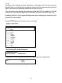
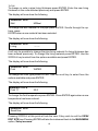
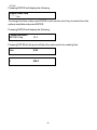
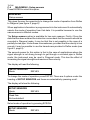
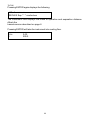
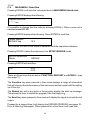
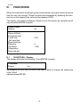
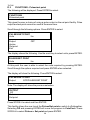
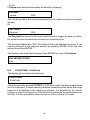
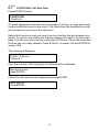
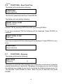
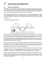
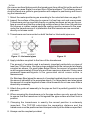
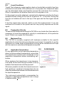
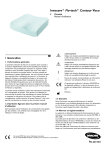
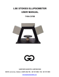
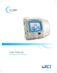
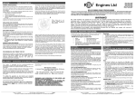
TUF330
TUF 330
INSTALLATION AND OPERATING
INSTRUCTIONS
1
TUF330
CONTENTS
A
INTRODUCTION
4
B
B.1
B.2
B.3
B.4
B.5
B.6
B.7
HARDWARE
Electronics Housing
Transducers
Transducer Connections
Transducer Hardware
Transducer Mounting
Transducer Cables
Keypad
4
5
5
6
6
9
9
C
C.1
C.2
C.3
C.4
C.5
C.6
MAIN MENU
Power up
Quick Start
View/Edit Site Data
Set-up Sensors
Calibrate 4-20mA
Read Flow
11
13
16
20
23
24
D
D.1
D.2
D.3
D.4
D.5
D.6
D.7
D.8
D.9
D.10
FUNCTIONS
Display
Set-up 4-20mA
Pulses/Set Point
CutOff M/S
Set Zero Flow
Reset Total Flow
Damping
Cal Factor
Diagnostics
Save And Exit
25
26
28
29
30
31
31
32
32
32
E
ERROR MESSAGES
33
F
WARNING MESSAGES
33
2
TUF330
G.
G.1
G.2
G.3
G.4
G.5
G.6
G.7
G.8
APPLICATION INFORMATION
Application Notes
Select a Metering Position
Mounting The Transducers
Liquid Conditions
Propagation Velocity
Maximum Flow
Application Temperature
Flow Range
34
35
36
38
38
38
38
38
H
SPECIFICATION
39
WARNING
Users should ensure or note that:
a) TUF330 is not certified for use in hazardous areas.
b) The local site safety regulations are complied with.
c) Work is carried out in accordance with The Health & Safety at Work Act 1974.
CE MARKING
The TUF330 has been tested and found to conform to EN50081 - 1 Emission Standards and EN50082
- 1 Immunity Standards.
The tests were conducted by AQL - EMC Ltd, of 16 Cobham Road, Ferndown Industrial Estate, Wimborne,
UK BH21 7PG.
The unit was tested with all cables as supplied of a maximum length of 3m. While the operation of the
unit may not be affected by the use of longer cables, Flotech can make no statement about conformance to the above standards when these cables are in use.
WARRANTY
The TUF330 Ultrasonic liquid flow meter is guaranteed by Flotech to be free from defects in materials
and workmanship for a period of one year from the date of shipment to the original customer, provided
that the equipment has been installed and used in the manner described in this User’s Manual. Fuses
and sensor cables are not included in this warranty.
If any problems develop, take the followings steps:
1) Notify Flotech or the Distributor from whom you purchased the meter giving full details of the problem. Be sure to include the model and serial numbers of your flow meter. You will then receive service
data and/or shipping instructions, depending on your problem.
2) If you are instructed to send your meter back to the factory, please send it prepaid to the authorised
repair station, as indicated in the shipping instructions.
The warranty of the TUF330 Ultrasonic Liquid Flow meter by Flotech is limited to those stated above
and Flotech will not be liable for anything beyond this.
3
TUF330
A.
INTRODUCTION
TUF330 is a “Clamp-on” liquid flow meter that uses the Transit Time method of
measurement to read flow. It is able to measure the flow of liquid in any pipe from
13mm to 5000mm, providing the pipe is flooded and the correct transducers are
used. Units are supplied according to application data provided by the customer.
The instrument displays volumetric flow rate in m3 /hr, m3 /min, m3 /sec, g/min,
USGal/hr, l/min, l/sec and linear velocity in metres and feet per second. The total
volume of flow will be displayed, up to a maximum 12-digit number. The flowmeter
is supplied with electronics, sensors and all mounting hardware.
B.
HARDWARE
Figure 1
B.1
Electronics Housing
An ABS housing with an opaque door contains
the master PCB. The housing is designed for
wall mounting using the brackets provided (see
Figure for mounting pattern). Drilling further
fixing holes in the Housing remove the IP67
protection rating and CE approval.
Mounting the housing into position does not
require the removal of the electronics or the front
display panel.
DO NOT PROVIDE POWER to the instrument until the service compartment
cover has been replaced.
The electronics are factory set for a particular supply voltage. Should it be
necessary to change the settings for the power supply see page 11, Power up.
Having completed the procedure for mounting the electronics, connecting all
cables and checking the power supply, the power can now be applied. TUF330 is
now ready for programming. A full programming procedure is described on page
11.
Before programming the instrument, it is necessary to attach the transducers to
the pipe wall such that they can be finally locked in the correct position based on
exact data provided by the instrument.
4
TUF330
B.2
TRANSDUCERS
Each instrument uses two identical transducers, which transmit and receive the
ultrasonic waves. They are clamped to the pipe surface using the mounting hardware supplied, as described on page 6.
The standard transducers are made from a Peek material with an aluminium plate
supporting the stud, used to lock the sensor in position. A flying armoured lead is
attached between the sensor block and the tuning circuit.
Transducers are supplied according to the pipe
size and flow velocity, and are available to meet
an operating temperature range from –20°C
up to +200°C.
Figure 2 – 1MHz Sensors with
TNC Coaxial Connector
B.3
Transducer Connections
Transducers are connected to the electronics from the tuning circuit by TNC
connectors. All other output and input connections are made through metal glands
to the clearly marked terminals. Only one current output can be used with the flow
meter.
Figure 3 - Transducer Connections
5
TUF330
B.4
Transducer Hardware
Transducer alignment guide rails, chains and couplant are supplied with all units
in order to ensure that the transducers are accurately aligned with respect to the
pipe axis. A single guide rail assembly is supplied for mounting the transducers in
Reflex mode and two guide rails are provided for mounting in Diagonal mode.
Figure 4 – 1MHz Reflex
Mounting Assembly
Figure 5 - Diagonal Beam
Mounting Hardware
B.5
Transducer Mounting
The two different methods of mounting the transducers are shown above. When
ordering the TUF330 specific application information should have been given.
This information determines the correct hardware to be supplied with each instrument.
Reflex Mode
Reflex mode is a default setting on all applications up to 215mm. Above this the
instrument will default to Diagonal mode. It is possible to change these default
settings if required (see page 20 Set up sensors).
Before attempting to attach the transducers it is imperative to ensure that the
correct position has been chosen to site the transducers and that the pipe surface conditions are suitable. Go to page 34 and carefully follow all instructions for
the selecting and preparing the transducer mounting site.
6
TUF330
At this point program the instrument to determine the separation distance. When
you have this information from the instrument follow the set up procedure below.
Reflex Set up Procedure
a) Insert the transducers into the guide rail so the tails come out of either end.
b) By turning the locking nut centre clockwise, withdraw the transducers up into
the guide rail.
c) Apply a bead of coupling grease to each transducer. See page 37, figure 12.
d) Attach both lengths of chain to the quick links provided and offer the guide rail
up to the pipe wall at 45°.
e) Wrap the chain around the pipe and connect to the ‘J’ bolt. Complete the same
for both ends of the guide rail then tighten the locking nuts on the ‘J’ bolt. This will
secure the complete assembly to the pipe.
f) By turning the centre of the locking assembly anti-clockwise lower one block
onto the pipe. Now adjust the second block to required separation distance and
repeat the procedure. The separation distance is measured from the front edge
of each block and not the centre of the locking nut. See figure 6.
g) If the instrument now reads a negative flow swapping the TNC connectors on
the instrument can change this.
h) Now lock the transducers in position by tightening the nut on locking assembly.
“DO NOT USE EXCESS PRESSURE”.
Note: When moving the transducers into position ensure that they are withdrawn
into the guide rail as far as possible. This ensures that the couplant will not be
removed from the transducer face before it is screwed down into position.
Figure 6
All transducers are mounted in Reflex or Diagonal mode as described on page 6.
The guide rail assemblies are held in position using chains.
7
TUF330
Diagonal Beam Mode
Diagonal beam mounting means the two transducer blocks are mounted on opposite sides of the pipe as shown in figure 7. This is the default setting for all
applications above 215mm.
If you encounter a difficult application or the maximum flow velocity is outside of
the default operating range, when working in the Reflex mode, it is possible to
reprogram the instrument to operate in Diagonal mode (see page 20, Set up
Sensors)
Diagonal Set up Procedure
a) Using whatever means available mark a reference line around the circumference of the pipe (reference line D). As shown in figure 7.
b) Locate and mark two positions exactly 180° apart around this reference line.
c) On both of these positions draw a reference line (E) perpendicular to line (D),
parallel to the pipe axis and approximately 1 metre long. See figure 7.
d) Take each of the guide rails and load the transducers as described previously
on page 5. Only one transducer goes in each guide rail.
e) Attach the one guide rail to the pipe using the chain provided, such that it is
parallel
to the reference line (E) and position so that the transducer face can be aligned
with reference line (D).
f) Program the flow meter and obtain the separation distance.
g) From the intersection of the circumference reference line (D) and the second
reference line (E) measure and mark the separation distance XXX. Now mount
the second guide rail such that the transducer face can be positioned on this
intersection ensuring that the guide rail is parallel to the reference line (E). See
figure 7.
h) Screw down both of the transducers and lock in position as previously
described.
Figure 7
8
TUF330
HINT: DRAWING A TRUE CIRCUMFERENCE AROUND A PIPE
An easy way to draw a perpendicular circumference around a large pipe is to
wrap a length of material such as chart paper around the pipe, aligning the edges
of the paper precisely at the overlap. With the edge of the chart paper being
parallel, then either edge describes a circumference around the pipe that is
perpendicular to the pipe axis.
BISECTING THE CIRCUMFERENCE
Mark the chart paper exactly where it overlaps. Then after removing the paper
from the pipe, fold the measured length in half keeping the edges parallel. The
fold line now marks a distance exactly half way around the pipe. Put the paper
back on the pipe and use the fold line to mark the opposite side of the pipe.
B.6
Transducer Cables
The transducers are connected to the electronics via 50ohm coaxial cables and
TNC connectors. The total length of the cable be up to a maximum of 200 mteres.
B.7
Keypad
All data is entered for set up and calibration via the front panel keypad.
Keys
•To give a NO answer and scroll through listed options, press SCROLL.
•To select options, store data and move on to the next option, press ENTER.
•If data has been incorrectly entered, press Y until the display is clear, then reenter the data correctly.
Restart Key
The RESTART key can be pressed at any point in the program and will take the
instrument back to the opening display. Press SCROLL to enter the password
2000 and reprogram the instrument. If the instrument has already been measuring flow and the SCROLL key is not pressed, it automatically returns to flow
mode.
Scroll Key
When the SCROLL key is pressed in flow mode the display will read the following.
Signal 80%
0.00 mA
This displays the signal level of the instrument and the current output status of the
4-20mA.
Press ENTER again and the following will be displayed.
ERRORS PENDING
No errors
9
TUF330
This will display all Error and Warning messages (see page 33). To program the
TUF330, accurate application data must be keyed in via the keypad. Data and
instructions are requested via the display and all questions must be answered
before the program will step through to the point of measuring flow.
Once the unit has been programmed the data can be reviewed and changed if
necessary.
The instrument displays information in the following 3 ways.
Flow in selected units.
l/min
l
0.00
0.00
The flow information can be factored to suit the users requirements by selecting
CAL FACTOR from the FUNCTIONS menu. The Totalised Flow data can also be
reset to zero.
10
TUF330
C.
PROGRAMMING/MAIN MENU
C.1
Power Up
DO NOT PROVIDE POWER TO THE INSTRUMENT UNTIL THE SERVICE
COMPARTMENT COVER HAS BEEN REPLACED.
The power supply is factory set. The right hand switch is used to change from
110 to 220VAC .
When power is applied to the TUF330 it will react in 2 distinctly different ways
depending upon whether any application data has been programmed into the
EEROM.
All new meters received from the factory will have had the EEROM memory wiped
clean.
Apply power. Initial display will show
iSOLV
Within 5 seconds the display will change to
DIMENSION
Millimetres
Application data can now be keyed in.
If the instrument has been used then application data will be stored in the EEROM
and the following will be displayed. If SCROLL is not pressed within 5 seconds
after the initial display, the instrument will go directly to flow mode.
Apply power. Initial display will show
iSOLV
PRESS SCROLL within 5 seconds of initial start up
Display will then show
ENTER PASSWORD
Key in password 2000 (only required if the unit has been previously used)
11
TUF330
ENTER PASSWORD
****
Display will show:
MAIN MENU
Quick Start
MAIN MENU
To get into the MAIN MENU press RESTART, SCROLL, then enter the password
2000. The MAIN MENU has 5 options that are selectable by using the scroll
key.
Press ENTER to select.
MAIN MENU
Quick Start
View/Edit Site
Setup sensors
Calibrate 4-20mA
Read flow
12
TUF330
C.2
MAIN MENU - Quick Start
The Quick Start option enables the user to quickly read flow.
The display will show the following.
MAIN MENU
Quick Start
Press ENTER to select this option and enter application data. The user now has
the option of selecting millimetres or inches.
Press SCROLL to display units and ENTER to select.
DIMENSION
Millimetres
Inches
The display will show the following. Enter the outside diameter and press
ENTER.
PIPE OD
mm/inches
Enter the wall thickness in the selected units and press ENTER.
WALL
mm/inches
THICKNESS
The display will show the following.
LINING THICKNESS
mm/inches
If the pipe has a LINING enter the thickness now and press ENTER. If there is no
LINING press ENTER to continue.
WALL
M/Steel
The display will show the following.
There are 11 wall material options that are selectable by using the scroll key.
13
TUF330
Select the material required and press ENTER when displayed.
WALL
M/Steel
S/Steel 316
S/Steel 303
Plastic
Cast Iron
Ductile Iron
Copper
Brass
Concrete
Glass
Other m/s
If Other m/s is selected the user needs to enter the speed of sound in metres per
second of the particular pipe material being used. Enter a figure and press ENTER. Contact Flotech if the sound speed is not known.
If a Lining material thickness has been selected the following is displayed.
LINING
Steel
There are 6 Lining material options that are selectable by using the scroll key.
These are only displayed if a Lining was selected previously.
Select the material required then press ENTER to select.
LINING
Steel
Rubber
Glass
Epoxy
Concrete
Other m/s
If Other m/s is selected the user needs to know the speed of sound in metres per
second of the particular lining material being used. Enter a figure and press
ENTER. Contact Flotech if the sound speed is not known.
14
TUF330
The display will show the following.
FLUID
Water
Press Scroll. There are 6 fluid options that are selectable by using the scroll
key.
Select the fluid required then press enter to select.
FLUID
Water
Glycol 50%
Lub oil
Diesel oil
Freon
Other m/s
If Other m/s is selected the user needs to know the speed of sound in metres per
second of the particular fluid being measured. Enter a figure and press ENTER.
Contact Flotech if the sound speed is not known.
The display will show the following.
FLUID TEMP
°C
To enter a minus temperature press Y on the keypad. When the temperature has
been entered press ENTER. The TUF330 has a temperature range between 20°C and +200°C.
If the temperature entered is out of range the following will be displayed.
Temp out of range
Press any key
When the correct temperature is entered the following will be displayed.
Approx. max flow
* * * * l/m
15
TUF330
The data that is entered and the application information that has been given to
Flotech when purchasing the equipment determine the approximate maximum
flow. The instrument will always default to litres per minute.
The instrument now displays the maximum flow rate that it is capable of with the
sensors provided and the application data that has been entered by the user.
Pressing SCROLL at this point will allow the user to change the units to be displayed in the flow mode.
Press ENTER when the units have been selected.
Approx max flow
* * * * l/s
* * * * l/m
* * * * Ml/d
* * * * g/m
* * * * kg/h
* * * * Usg/m
* * * * Uskg/h
* * * * m3/h
* * * * m3/m
* * * * m3/s
* * * * m/s
* * * * ft/s
The following will now be displayed.
Attach sensors
REFLEX Sep * * * mm/inches
Pressing ENTER at this point will take the instrument into reading flow.
l/m
l
0.00
000.0
16
TUF330
C.3
MAIN MENU - View/Edit Site
From the MAIN MENU select View/Edit site data by pressing ENTER. This
enables the user to view and edit the application data that has been entered into
the unit previously.
The display will show the following. Press ENTER to select.
l/m
l
0.00
000.0
The display will show the following. Press ENTER to select.
MAIN MENU
View/Edit Site
The display will show the following.
VIEW/EDIT SITE
Dimension
MM/INCHES
To change the dimensions press ENTER. Select the units by pressing SCROLL.
Press ENTER to select. This will convert all previous data entered, into the units
selected.
The display will now show the following.
VIEW/EDIT SITE
Pipe OD
55.0
To change the outside diameter of the pipe press ENTER. Enter the new outside
diameter in the units selected previously and press ENTER.
The display will now show the following.
VIEW/EDIT
Wall thickness3.0
SITE
To change the pipe wall thickness press ENTER. Enter the new wall thickness in
the units selected and press ENTER.
The display will now show the following.
VIEW/EDIT SITE
Lining thick
0.0
17
TUF330
To change or enter a pipe lining thickness press ENTER. Enter the new lining
thickness in the units selected previously and press ENTER.
The display will now show the following
VIEW/EDIT SITE
Wall
M/Steel
To change the wall material of the pipe press ENTER. Scrolls through the options, press
ENTER when a new material has been selected.
The display will now show the following.
VIEW/EDIT SITE
Lining
——
It will only be possible to change the pipe lining material if a lining thickness has
been entered previously. To change the lining material press ENTER. Use the
SCROLL key to select from the options available and press ENTER.
The display will now show the following.
VIEW/EDIT SITE
Fluid
WATER
To change the fluid type press ENTER. Use the scroll key to select from the
options available and press ENTER.
The display will now show the following.
VIEW/EDIT SITE
Fluid °C
20.0
To change the fluid temperature press ENTER. Press ENTER again when a new
temperature has been entered.
The display will now show the following.
VIEW/EDIT SITE
Read flow
Pressing SCROLL at this point will ask the user if they wish to exit the VIEW/
EDIT SITE loop.Pressing ENTER will take the instrument back to the MAIN MENU
option, Setup sensors.
18
TUF330
Pressing ENTER will display the following.
Approx max flow
* * * * l/m
To change the flow units press SCROLL and use the scroll key to select from the
options available and press ENTER.
Pressing ENTER will display the following.
Attach sensors
REFLEX Sep
10.2
Pressing ENTER at this point will take the instrument into reading flow.
l/m
0.00
l
000.0
19
TUF330
C.4
MAIN MENU - Setup sensors
Press ENTER to select this option.
MAIN MENU
Setup sensors
This gives the user the opportunity to change the mode of operation from Reflex
to Diagonal (see figure 5, page 6).
When application information is programmed into the instrument it automatically
selects the mode of operation from that data. It is possible however to use the
same sensors in different modes.
The Setup sensors option is available for two main reasons. Firstly, if from the
data that has been entered the instruction comes back that the sensors should be
mounted in Diagonal mode, it may be that this is not possible in the case of a
partially buried pipe. Under these circumstances, provided that the velocity is low
enough it may be possible to use the transducers provided in Reflex mode (see
figure 4, page 6).
The second reason for this option is that in the case of applications where the
signal strength is not strong enough to get through a corroded pipe in Reflex
mode, the instrument may be used in Diagonal mode. This has the effect of
increasing the signal strength and maximum flow velocity.
The display will read the following.
SETUP SENSORS
Mode
REFLEX
To change the mode of operation press ENTER. There are 4 options under the
heading of SETUP SENSORS and these are selectable by pressing scroll.
The display will show the following.
SETUP SENSORS
Mode
Sensor params
Read flow
Exit and default
REFLEX
Select mode of operation by pressing SCROLL
SETUP SENSORS
Mode
REFLEX
20
TUF330
The display will show the following.
MODE
Reflex
Pressing SCROLL will allow you to choose between Reflex and Diagonal operation. Press
ENTER when new mode is selected.
The display will show the following.
SETUP SENSORS
Sensor params
The user cannot change this option. It is only used by Flotech engineers to set
sensor parameters for a particular application and to make sure the correct
transducers are supplied with the instrument. If this option is selected in error the
instrument will ask for a password that is only known by Flotech engineers. Pressing
SCROLL will move the instrument onto the next option.
The display will show the following.
SETUP SENSORS
Read flow
If the sensor mode has been changed from the default settings (i.e. Reflex to
Diagonal or
Diagonal to Reflex) then this option will have to be selected to make sure that the
new mode of operation is used to read flow. If this is not selected the default
settings will be used.
The display will show the following.
SETUP SENSORS
Exit and default
Press ENTER at this point to Exit and return to the MAIN MENU. This will re-set all
the default sensor settings in the instrument that may have been changed by the
user.
Pressing ENTER to continue will display the following.
Approx max flow
* * * * l/m
21
TUF330
Pressing ENTER again displays the following.
Attach sensors
REFLEX Sep * * * mm/inches
The instrument now displays the mode of operation and separation distance.
Attach the
transducers as described on page 6.
Pressing ENTER will take the instrument into reading flow.
l/m
l
0.00
000.0
22
TUF330
C.5
MAIN MENU - Calibrate 4-20mA
(Note: A meter is required to measure the output current)
The display will read the following. Press ENTER to select.
MAIN MENU
Calibrate 4-20mA
The 4-20mA output is calibrated before it leaves the factory and should not need
adjusting, although this option allows the user to adjust it if necessary to match a
specific requirement. The DAC value is a number between 0 and 40,000, which is
a number internal to the TUF330.
The first stage is to adjust the output current to 4mA. Use the scroll key, decimal
point key or keys 5 and 6. The scroll and decimal point key move the DAC value in
large steps of 25. Keys 5 and 6 move the value one digit at a time.
The DAC value should be approximately 8000 for 4mA and 40,000 for 20mA. By
watching the actual current value displayed on the meter, it is possible to set this
exactly.
The display will show the following.
CAL 4mA
DAC value:
8000
Use the scroll and decimal point key to set and keys 5 and 6 to trim. Press ENTER
when
complete.
The display will then show the following.
CAL 20mA
DAC value:
40000
Use the scroll and decimal point key to set 20mA and keys 5 and 6 to trim. Press
ENTER when complete.
The following will be displayed. Press SCROLL.
MAIN MENU
Calibrate 4-20mA
The following will be displayed.
MAIN MENU
Read flow
23
TUF330
C.6
MAIN MENU - Read flow
Pressing SCROLL will take the instrument back to MAIN MENU-Quick start.
Pressing ENTER displays the following.
Approx max flow
* * * * l/m
It is possible to change the flow units by pressing SCROLL. When a new unit is
selected press ENTER.
Pressing ENTER displays the following. Press ENTER to read flow.
Attach sensors
REFLEX Sep
10.2
This informs the user of the mode of operation and the separation distance.
Pressing SCROLL takes the instrument into SETUP SENSOR mode.
SETUP SENSORS
Mode
REFLEX
Pressing ENTER will read flow.
l/m
l
0.00
0.00
There are three keys that are active. FUNCTION, RESTART and SCROLL. (see
also page 11)
The Function key when pressed in flow mode displays a range of information
that will improve the performance of the instrument and will assist with the setting
up of the unit.
The Restart key will at any point in the program display the start up message.
This allows the user to restart the program from the beginning.
The Scroll key when pressed in flow mode will display the signal level and the mA
output.
Pressed for a second time it will display the ERRORS PENDING (see page 33 Error & Warning Messages). When pressed for a third time it will read flow.
24
TUF330
D.
FUNCTIONS
When the instrument is performing the measurement, there are certain functions
that the user can access. These functions are accessible by pressing the function key on the keypad then entering the password 2000.
The display will read the following. Select one of the options by using the scroll
key and press ENTER to select.
FUNCTIONS
Display
l/m
Setup 4-20mA
Pulses/set point
Cutoff m/s
Set zero flow
Reset total flow
Damping
Cal factor
Diagnostics
Save and exit
0.05
5
1.000
D.1
FUNCTIONS – Display
The display will show the following. Press ENTER to select.
Functions
Display
l/m
By pressing ENTER then SCROLL the user is able to change the measuring
units. When
selected press ENTER.
25
TUF330
D.2
FUNCTIONS - Setup 4-20mA
The display will show the following. Press ENTER to select.
Functions
Setup 4-20mA
The display will show the following. Scroll through each item and press ENTER to
select.
SETUP 4-20MA
mA out
Output
Units
Max.
Min.
mA on error
Exit
0.00
OFF
l/m
1000
0.00
22.0
The display will show the following. Press Enter to select.
SETUP 4-20MA
Output
OFF
This shows the user what the output is giving at any particular time. Press SCROLL
to continue.
The display shows the following. Select the output required and press ENTER.
OUTPUT
OFF
4-20mA
0-20mA
0-16mA
It is possible to choose between switching the output ON/OFF or selecting the
output required by pressing SCROLL and ENTER.
SETUP 4-20MA
Units
l/m
It is possible to set the output different from that on the display. For example the
display may show gallons/minute but the output needs to be set up in m3 /hour.
Scroll through the options and press ENTER to select.
26
TUF330
The display will show the following.
SETUP 4-20MA
Max.
1000
This function allows the user to scale the 4-20mA. Press ENTER to select and
enter your required maximum flow rate in the units selected. For example when
the flow rate reaches the maximum set, the output will be 20mA. Press ENTER
when complete.
The display will show the following.
SETUP 4-20MA
Min.
000
The user is now required to enter the minimum flow rate required in the units
selected. Press ENTER when complete.
The display will show the following.
SETUP 4-20MA
mA on error
22
This gives an error output which would inform the user of loss of signal. This can
be set to any figure between zero and 24mA, but defaults to 22mA. Press ENTER
to select, enter the figure required and press ENTER.
The display will show the following.
SETUP 4-20MA
Exit
Press SCROLL to stay in the SETUP 4-20mA menu or ENTER to go back to the
FUNCTIONS menu.
27
TUF330
D.3
FUNCTIONS - Pulses/set point
The following will be displayed. Press ENTER to select.
FUNCTIONS
Pulses/set point
This gives the user a choice of using a pulse output or the set point facility. Pulse
output and set point cannot be used at the same time.
Scroll through the following options. Press ENTER to select.
PULSES/SET POINT
Units
l/m
Output
l/pulse
Set point
Exit
OFF
The display shows the following. Use the scroll key to select units, press ENTER.
PULSES/SET POINT
Units
l/m
At this point the user is able to select the units required by pressing ENTER.
Scroll through the options required and press ENTER when selected.
The display will show the following. Press ENTER to select.
PULSES/SET POINT
Output
OFF/PULSES/SET POINT
Note: The display will show the previous selection.
OUTPUT
Off
Pulses
Set point
Press SCROLL to select and then ENTER.
This facility allows the user to set the Pulses/Set point or switch it off altogether.
Selecting Off and pressing ENTER will move the program to Cutoff m/s. Press
SCROLL to select Pulses or Set point and press ENTER.
28
TUF330
If Pulses were selected the display will show the following.
PULSES
l/pulse
1000
This can be scaled to the users requirements up to a maximum of one pulse per
second.
Or
SET POINT
Set point
1000
The Set point can be set to the users requirements to trigger an alarm or indicator, when the flow has reached a minimum or maximum level.
The instrument defaults to 1000. This will be in the units selected previously. It can
now be changed to the required amount by pressing ENTER. Enter the new
amount then press ENTER.
The display now reads the following. Press ENTER to return to Functions.
PULSES/SET POINT
Exit
D.4
FUNCTIONS - Cutoff m/s
The display will now show the following.
FUNCTIONS
Cutoff m/s
The instrument has a preset CUTOFF of 0.05m/sec, which has been programmed
into the instrument. Flotech cannot guarantee measuring flows below this range
because of instabilities in the measuring process. It is possible for the user to
change or cancel this figure but Flotech cannot guarantee the performance below this. It is also possible to enter any figure up to a velocity of 1m/sec.
29
TUF330
D.5
FUNCTIONS - Set Zero Flow
Press ENTER to select.
FUNCTIONS
Cutoff m/s
On some applications the instrument is capable of picking up noise which may
show a small offset when in flow mode. This offset should be cancelled out which
will increase the accuracy of the instrument.
Before this function is used you have to be sure that the flow has stopped completely. To set zero flow before the flow has stopped will result in an error message. This will occur when the flow is still above 0.25m/sec. This could mean that
the flow has not totally stopped. Press SCROLL to answer NO and ENTER to
answer YES.
The following is displayed.
FLOW > 0.25 m/s
Continue ?
If the flow is below 0.25 m/sec then the following will be displayed.
Stop the flow and
press ENTER
Follow the instructions on the display by pressing ENTER.
Zero flow set
Press ENTER
30
TUF330
D.6
FUNCTIONS - Reset Total Flow
The display will now show the following.
FUNCTIONS
Reset total flow
This function resets the total Flow. Press ENTER.
The display will now ask the following.
RESET TOTAL FLOW
Are you sure?
Answer YES by pressing ENTER and NO by pressing SCROLL.
If you have answered YES the following will be displayed. Press SCROLL to
continue.
RESET TOTAL FLOW
Total reset
If you have answered NO the following will be displayed. Press SCROLL to continue.
FUNCTIONS
Reset total flow
D.7
FUNCTIONS – Damping
The display will show the following.
FUNCTIONS
Damping
5
This option is used when flow readings are unstable due to turbulence caused by
internal obstructions or bends etc. Damping or averaging can be used to make
the readings more stable. It can be set to up-date the display between every 3 to
100 seconds. Press ENTER to select. Enter the time in seconds then press
ENTER.
31
TUF330
D.8
FUNCTIONS - Cal Factor
The display will show the following.
FUNCTIONS
Cal factor
1.000
This facility should never have to be used if the correct application data has been
entered into the unit when being installed.
The calibration factor enables the instrument to be calibrated to any existing
meter or flow rate. The transducers are always calibrated to work with the electronics supplied. If for any reason the transducers are damaged the new ones
supplied will not have been calibrated with the electronics. The calibration factor
could then be used to give the same reading as other transducers.
If the new reading is 4% higher than normal then entering 0.96 will reduce the
flow reading by 4%. If the reading is 4% lower than normal, entering 1.04 would
increase the reading by 4%. When the instrument is supplied it will always default
to 1.00. If it has to be changed the new cal number will stay in the memory until
changed again. Press ENTER to select. Enter new data and press ENTER.
D.9
FUNCTIONS - Diagnostics
The display will now read.
FUNCTIONS
Diagnostics
Diagnostics is not an option for the user. The numbers displayed cannot be
changed in any way and are only of benefit to Flotech engineers when testing the
instrument or fault finding. Press SCROLL to continue.
D.10 FUNCTIONS - Save and Exit
The display now reads.
FUNCTIONS
Save and exit
Press SCROLL to start at the beginning of the FUNCTIONS menu again or ENTER to save all the changes made and read flow.
32
TUF330
E
ERROR and WARNING MESSAGES
E1:
High Flow
When the instrument is programmed the user is informed of the maximum flow
rate that the instrument can measure. If this is exceeded the High flow message
occurs.
It may be possible to get round these problems by using another set of transducers in another mode. This should not be necessary as the unit would have been
supplied for a particular application with the correct transducers.
E2:
No Flow Signals
This message appears when the two transducers cannot send or receive signals.
This could happen for a variety of reasons. Firstly check that all cables are connected, transducers are on the pipe correctly and at the correct separation distance. Check that there is couplant on the transducers.
This message may also appear when trying to measure a partially full pipe, aerated liquid or when the particulate content of that liquid is too high. The condition
of the pipe being measured could also be a problem.
F
WARNING MESSAGES
W1:
Check Data
This message occurs when the application information has been entered incorrectly or the transducers have been attached to the wrong pipe size. This will
cause the timing to be in error. The site data needs to be checked and the instrument reprogrammed.
W2:
Timing Poor
Unstable signal timing or differing up/down stream times indicate that the liquid is
aerated or pipe surface is of poor quality.
W3:
Signals Poor
This warning appears when there is a signal lower than 25%. This could be due to
the application or a poor quality pipe etc.
W4:
mA (1) Over
The mA (1) output is over range when the Flow is higher than the maximum mA
range.. It is possible to re-scale the 4-20mA to be able to cope with the higher
range.
W6:
Pulse at Max
This message occurs when the pulses have exceeded the maximum setting. It is
possible to re-scale the pulse output to cope with the higher flow rate.
33
TUF330
G.
ADDITIONAL INFORMATION
G.1
APPLICATION NOTES
TUF330 is a “Transit Time” Ultrasonic flowmeter which has been designed to work
with “Clamp On” transducers, thus enabling liquid flowing within a closed pipe to
be measured accurately without the need for any mechanical parts to be inserted
either through the pipe wall or protrude into the flow system.
The meter is controlled by a micro-processor containing a wide range of data
which enables the instrument to measure flow in any pipe diameter from 13mm
bore up to 5000mm, made of any material and over a wide range of operating
temperatures.
The system operates as follows:
When ultrasound is transmitted from transducer “X” to transducer “Y” the speed
at which the sound travels through the liquid is accelerated slightly by the velocity
of the liquid. If sound is transmitted in the opposite direction from “Y” to “X” it is
decelerated because it is travelling against the flow of the liquid. The difference in
time taken to travel the same distance but in opposite directions is directly proportional to the flow velocity of the liquid.
Having measured the flow velocity and knowing the pipe cross-sectional area, the
volumetric flow can be easily calculated. All of the calculations required to first
determine the correct siting of the transducers and subsequently compute the
actual flow are carried out by the microprocessor.
To measure flow, it is first necessary to obtain detailed information about each
application, which is then programmed into the processor via the keypad. This
information must be accurate otherwise flow measurement errors will occur.
Further having calculated the precise position at which the transducers must be
clamped onto the pipe wall, it is equally important to align and separate the transducers accurately with respect to one another, as failing to do so will again cause
errors in measurement.
34
TUF330
Finally to ensure accurate flow measurement it is imperative that the liquid is
flowing uniformly within the pipe and that the flow profile has not been distorted by
any upstream or downstream obstructions.
To obtain the best results from the TUF330 it is absolutely necessary that the
following rules for positioning the transducers are adhered to and that the condition of the liquid and the pipe wall are suitable to allow transmission of the sound
along its predetermined path.
G.2
Selecting A Meter Position
As the transducers with theTUF330 are clamped to the outside surface of the
pipe, the meter has no way of determining exactly what is happening to the liquid.
The assumption therefore has to be made that the liquid is flowing uniformly along
the pipe, either under fully turbulent conditions or under laminar flow conditions.
It is further assumed that the flow velocity profile is uniform for 360° around the
pipe axis. The TUF330 is normally supplied calibrated for use on turbulent flows
but by adjustment of the CAL FACTOR the instrument can be used for laminar
flow applications.
Figure 8
Figure 8 shows a uniform profile as compared to a distorted profile.
(a)
(b)
The difference between (a) and (b) is that the “Mean Velocity” of the flow across
the pipe is different and the TUF330 expects a uniform flow as in (a). The distorted flow in (b) will give measurement errors which cannot be predicted or
compensated for.
Flow profile distortions result from upstream disturbances such as bends, tees,
valves, pumps and other similar obstructions. To ensure a uniform profile the
transducers must be mounted far enough away from any cause of distortion such
that it no longer has an effect.
35
TUF330
Figure 9
The minimum length of upstream straight
pipe is 20 diameters and 10 diameters
downstream which ensures that accurate results will be achieved. Flow measurements can be made on shorter
lengths of straight pipe down to 10 diameters upstream and 5 diameters
downstream, but when the transducers
are sited this close to any obstruction
errors can be considerable.
It is not possible to predict the amount of error as this depends entirely upon the
type of obstruction and the configuration of the pipework. The message therefore
is clear. Do not expect to obtain accurate results if the transducers are positioned
closer than allowed to any obstruction that distorts the uniformity of the flow
profile.
Examples of the effects of two different pipe configurations are shown in Figure
10.
Figure 10
G.3
Mounting the Transducers
It will be impossible to achieve the accuracy of measurement specified for the
TUF330 if the transducers are not clamped to the pipe correctly and if the
data - I.D., O.D., Temperature, Pipe Material are not accurate.
The transducers are supplied with a guide rail, the purpose of which is to ensure
that the transducers are aligned accurately with the pipe axis and that the face of
the sensor is tangential to the axis.
Apart from the correct positioning and alignment of the transducers, of equal
importance is the condition of the pipe surface in the area under each of the
transducers.
36
TUF330
An uneven surface that prevents the transducers from sitting flat on the surface of
the pipe can cause Signal Level and Zero Offset problems. The following procedure is offered as a guide to good practice with respect to positioning and mounting the transducers.
1. Select the meter positioning as according to the rules laid down on page 35.
2. Inspect the surface of the pipe to ensure it is free from rust and unevenness.
Transducers can be mounted directly on painted surfaces as long as the sur
face is smooth and that the underlying metal surface is free from rust particles.
On bitumen or rubber coated pipes the coating must be removed in the area
under the transducers as it is preferable that the transducers are mounted
directly on to base metal.
3. Transducers can be mounted on both Vertical or Horizontal pipe runs.
Figure 11 - Horizontal pipes
Figure 12
4. Apply interface couplant to the face of the transducers.
The amount of couplant used is extremely important particularly on pipes of
less than 100mm bore. Use the syringe supplied with the instrument and apply
couplant as shown. On small pipes below 90mm the amount of grease used
must be approximately 20mm long and 2mm maximum diameter. Using more
grease will cause wall signals to be generated which cause errors in
measurement.
On Stainless Steel pipes the amount of couplant applied should never exceed
the amount indicated in the examples above. For large plastic and steel pipes
the amount of couplant applied is less critical however do not use more than is
absolutely necessary.
5. Attach the guide rail assembly to the pipe so that it is perfectly parallel to the
pipe axis.
6. When screwing the transducers on to the pipe surface use only enough force
to ensure that the transducer is flat against the pipe surface and then lock in
position.
7. Clamping the transducers in exactly the correct position is extremely
important. The TUF330 calculates the separation distance and the
transducers must be positioned and clamped exactly at the distance specified.
8. Always use the couplant provided.
37
TUF330
G.4
Liquid Conditions
Transit Time ultrasonic meters perform best on liquids that are totally free from
entrained air and solids. With sufficient air in the system the Ultrasound beam
can be attenuated totally and therefore prevent the instrument from working.
Often it is possible to tell whether there is air in the system or not.
If a flow signal cannot be obtained, a simple test to determine whether the flow is
aerated involves cutting off the flow for a period of 10 - 15 minutes. During this
time the air bubbles will rise to the top of the pipe and the flow signal should
return.
If the flow signal does returned, switch on the flow measurement. If not, the
entrained air is locked in the system and will very quickly disperse and kill the
signal.
G.5
Propagation Velocity
To make a flow measurement using theTUF330 on any liquid other than water it is
necessary to know the propagation velocity in metres/second, of the particular
liquid. Flotech can supply this information.
G.6
Maximum Flow
The TUF330 is normally supplied with hardware suitable for the specific
application for which the instrument has been purchased. It is possible to use the
instrument on a wide range of applications as long as the transducers will cope
with the maximum velocity and temperature required.
G.8
G.7
Application Temperature
On any application with an operating temperature
above or below ambient temperature, ensure that
the transducers reached and maintained at the
application temperature before undertaking calibration.
FLOW RANGE
When applying the transducers to low temperature pipes, do not allow the pipe surface to ice up
between the transducers and the pipe wall.
Wherever possible insulate the transducers such Figure 13
that variations in ambient air temperature do not
effect the relationship between the transducers and
the liquid temperature.
The instrument automatically compensates for
changes in application temperature over a range
of approximately +20oC.
38
TUF330
H
SPECIFICATION
ELECTRONIC ENCLOSURE:
Protection Class
Material
Dimensions
Display
Keypad
Sensor Connections
All Other Connections
Temperature Range
IP67
ABS
264 x 230 x 101 mm
2 x 16 Character Super Twist LCD backlit
16 key tactile membrane
TNC Coax Connectors
IP65 Glands
0°C to 50°C Operating
-10°C to 60°C Storage
SUPPLY VOLTAGE:
Switchable
110–240 VAC ± 50/60 Hz Max. 5 watts
24 VDC (option)
FLOW OUTPUTS:
Flow Display
Analogue
Set Point or Pulse
Volumetric Flow
Flow Velocity
Flow Rate
Total Flow
Signal Level Indication
ERROR messages
4 - 20mA into 750Ω
Resolution
Max. 1 pulse per second
Pipe Sizes
‘A’ 13 mm…89 mm
m3 , litres, gallons (Imperial and US)
metres/sec, feet/sec
0.2…12 m/sec to 4 Significant Figures
12 Digits
Opto isolated with user definable scaling
0.1% of full scale
User definable scaling
Flow Velocity Range
‘B’ 90 mm…1000 mm
‘C’ 300 mm…2000 mm
‘D’ 1000 mm…5000 mm
0.2 m/sec…4 m/sec (8 m/sec)
0.2 m/sec…8 m/sec (12 m/sec)
0.2 m/sec…4 m/sec (7 m/sec)
0.2 m/sec…4 m/sec (7.5 m/sec)
Frequency:
Flow Transducer Protection:
Flow Transducer Cables:
Flow Transducer Cable Length:
1MHz, 2MHz, 0.5MHz
Standard: IP65
50 Ohm Coax Cable
3 metres Standard - Optional up to 200
Flow Transducer Temp. Range:
-20°C to +200°C (‘D’ only up +80°C)
metres
ACCURACY:
± 1…2% of reading or ± 0.02 m/sec, whichever is the greater.
Specification assumes turbulent flow profile with Reynolds numbers above 4000.
REPEATABILITY:
± 0.5% with unchanged transducers position.
PIPE MATRIALS:
Any sonic conducting medium such as Carbon Steel, Stainless Steel, Copper, UPVC, PVDF, Concrete,
Galvanised Steel, Mild Steel, Glass, Brass. Includes lined pipes – Epoxy, Rubber Steel, Plastic.
Flotech reserve the right to alter any specification without notification.
39