1
Volume 3 Issue 9 January 2001 Copyright © 1999 Wimborne Publishing Ltd and Maxfield & Montrose Interactive Inc EPE Online, Febuary 1999 - www.epemag.com - XXX Copyright 2001, Wimborne Publishing Ltd (Allen House, East Borough, Wimborne, Dorset, BH21 1PF, UK) and Maxfield & Montrose Interactive Inc., (PO Box 857, Madison, Alabama 35758, USA) All rights reserved. WARNING! The materials and works contained within EPE Online — which are made available by Wimborne Publishing Ltd and Maxfield & Montrose Interactive Inc — are copyrighted. You are permitted to make a backup copy of the downloaded file and one (1) hard copy of such materials and works for your personal use. International copyright laws, however, prohibit any further copying or reproduction of such materials and works, or any republication of any kind. Maxfield & Montrose Interactive Inc and Wimborne Publishing Ltd have used their best efforts in preparing these materials and works. However, Maxfield & Montrose Interactive Inc and Wimborne Publishing Ltd make no warranties of any kind, expressed or implied, with regard to the documentation or data contained herein, and specifically disclaim, without limitation, any implied warranties of merchantability and fitness for a particular purpose. Because of possible variances in the quality and condition of materials and workmanship used by readers, EPE Online, its publishers and agents disclaim any responsibility for the safe and proper functioning of reader-constructed projects based on or from information published in these materials and works. In no event shall Maxfield & Montrose Interactive Inc or Wimborne Publishing Ltd be responsible or liable for any loss of profit or any other commercial damages, including but not limited to special, incidental, consequential, or any other damages in connection with or arising out of furnishing, performance, or use of these materials and works. ISSN 0262 3617 PROJECTS . . . THEORY . . . NEWS . . . COMMENTS . . . POPULAR FEATURES . . . VOL. 30. No. 9 SEPTEMBER 2001 Cover illustration by Jonathan Robertson www.epemag.wimborne.co.uk EPE Online: www.epemag.com Projects and Circuits WATER MONITOR by John Becker How costly is it to keep your garden watered? Find out and control it 616 INGENUITY UNLIMITED hosted by Alan Winstanley Wien Bridge Audio Generator; Precision Stereo Volume Control 626 L.E.D. SUPER TORCHES by Andy Flind Two hi-tech (one super-hi-tech!) designs to brighten your nights 628 PERPETUAL PROJECTS – 3 by Thomas Scarborough 644 Three more solar-powered projects – Loop Burglar Alarm, Touch-Switch Door-Light, Solar-Powered Rain Alarm – plus seven suggestions for variants SYNCHRONOUS CLOCK DRIVER by Andy Flind By popular request – a dual-frequency, 50Hz-60Hz converter for mains operated synchronous clocks 660 Series and Features NEW TECHNOLOGY UPDATE by Ian Poole Small is efficient when it comes to packaging CONTROLLING FLIGHT by Owen Bishop An insight into how electronics helps to maintain aircraft safety PRACTICALLY SPEAKING by Robert Penfold A novice’s guide to why some pins can be left unconnected NET WORK – THE INTERNET PAGE surfed by Alan Winstanley CIRCUIT SURGERY by Alan Winstanley and Ian Bell Curious Decoupling; Some Like it Hot 622 638 654 658 666 Regulars and Services WE HAVE MOVED! Please note our new address and phone/fax numbers – see page 615 © Wimborne Publishing Ltd 2001. Copyright in all drawings, photographs and articles published in EVERYDAY PRACTICAL ELECTRONICS is fully protected, and reproduction or imitations in whole or in part are expressly forbidden. Our October 2001 issue will be published on Thursday, 13 September 2001. See page 607 for details Everyday Practical Electronics, September 2001 EDITORIAL NEWS – Barry Fox highlights technology’s leading edge Plus everyday news from the world of electronics READOUT John Becker addresses general points arising ELECTRONICS VIDEOS Our range of educational videos SHOPTALK with David Barrington The essential guide to component buying for EPE projects PLEASE TAKE NOTE Shortwave Loop Aerial BACK ISSUES Did you miss these? Some now on CD-ROM! CD-ROMS FOR ELECTRONICS Electronic Projects; Filters; Digital Works 3.0; Electronic Circuits and Components V2.0; Digital Electronics; Analogue Electronics; PICtutor; Modular Circuit Design; Electronic Components Photos; C for PIC Micros; CAD Pack ELECTRONICS MANUALS Essential reference works for hobbyists, students and service engineers DIRECT BOOK SERVICE A wide range of technical books available by mail order PRINTED CIRCUIT BOARD AND SOFTWARE SERVICE PCBs for EPE projects. Plus EPE software ADVERTISERS INDEX 615 623 635 642 650 650 652 656 668 670 673 676 Readers Services ) Editorial and Advertisement Departments 615 605 NEXT MONTH PIC TOOLKIT TK3 FOR WINDOWS Designed explicitly for running in the “desk-top PC” environments of Windows 95 and 98, the software for Toolkit TK3 is intuitively easy to use, fast in operation, has many extra features that are probably not found elsewhere, and is the ideal programming aid for all who love to play with reprogrammable PICs. It is equally suited to TASM and MPASM programming dialects. The accompanying p.c.b. caters for 8-, 18-, 28- and 40-pin PIC sizes. These can be hard-wired not only to integral onboard hardware, but also to external components in conjunction with a plug-in breadboard. In this context, it is not only a programmer, but its options are also closely allied to the facilities available on the highly successful EPE PIC Tutorial board of March to May ’98. The PIC families catered for are principally the PIC16x84 and PIC16F87x EEPROM-based series. It is likely that the system can be used with other PICs that also have 14-bit program codes. The new software can also be used with the Toolkit V2.4 board, originally released in May/June ’99. TRAFFIC CONTROL TWO-VALVE SW RECEIVER Never let us be accused of lagging behind the times. Get right up to date with this Two-Valve Shortwave Receiver. Well maybe it’s not the very latest technology but this fascinating retro project is fun to build and use, and the components are still easy to obtain. This battery powered set is of the type that was the norm in the 60s. It covers the range 5MHz to 30MHz and, although a bit of “chassis bashing” is involved, it is easy to build and use. Go back in time next month – it will give you a warm glow! We hear much about air traffic controllers, but more important to our daily lives are those relatively inconspicuous systems and people who control the flow of traffic in our busy cities. This article describes how electronics and computers are used to make their work possible. For instance, vehicles approaching many junctions are detected by inductive loops. Changes in inductance change the input to the control computer that is located beside the road junction. Information from the inductive loops can tell the computer the length of the traffic queue at the lights and also the speed and approximate size of vehicles approaching them. It’s all explained in this feature article. PLUS ALL THE REGULAR FEATURES NO ONE DOES IT BETTER DON'T MISS AN ISSUE – PLACE YOUR ORDER NOW! Demand is bound to be high OCTOBER 2001 ISSUE ON SALE THURSDAY, SEPTEMBER 13 Everyday Practical Electronics, September 2001 607 QUASAR ELECTRONICS Limited Established 1990 Unit 14 Sunningdale, BISHOPS STORTFORD, Herts. CM23 2PA TEL: 01279 306504 FAX: 07092 203496 ADD £2.00 P&P to all orders (or 1st Class Recorded £4, Next day (Insured £250) £7, Europe £5.00, Rest of World £10.00). We accept all major credit cards. Make cheques/PO's payable to Quasar Electronics. Prices include 17.5% VAT. MAIL ORDER ONLY FREE CATALOGUE with order or send 2 x 1st class stamps (refundable) for details of over 150 kits & publications. PROJECT KITS * 2 x 25W CAR BOOSTER AMPLIFIER Connects to the output of an existing car stereo cassette player, CD player or radio. Heatsinks provided. PCB 76x75mm. 1046KT. £24.95 * 3-CHANNEL WIRELESS LIGHT MODULATOR No electrical connection with amplifier. Light modulation achieved via a sensitive electret microphone. Separate sensitivity control per channel. Power handing 400W/channel. PCB 54x112mm. Mains powered. Box provided. 6014KT £24.95 * 12 RUNNING LIGHT EFFECT Exciting 12 LED light effect ideal for parties, discos, shop-windows & eye-catching signs. PCB design allows replacement of LEDs with 220V bulbs by inserting 3 TRIACs. Adjustable rotation speed & direction. PCB 54x112mm. 1026KT £15.95; BOX (for mains operation) 2026BX £9.00 * DISCO STROBE LIGHT Probably the most exciting of all light effects. Very bright strobe tube. Adjustable strobe frequency: 1-60Hz. Mains powered. PCB: 60x68mm. Box provided. 6037KT £28.95 * ANIMAL SOUNDS Cat, dog, chicken & cow. Ideal for kids farmyard toys & schools. SG10M £5.95 * 3 1/2 DIGIT LED PANEL METER Use for basic voltage/current displays or customise to measure temperature, light, weight, movement, sound levels, etc. with appropriate sensors (not supplied). Various input circuit designs provided. 3061KT £13.95 * IR REMOTE TOGGLE SWITCH Use any TV/VCR remote control unit to switch onboard 12V/1A relay on/off. 3058KT £10.95 SPEED CONTROLLER for any common DC motor up to 100V/5A. Pulse width modulation gives maximum torque at all speeds. 5-15VDC. Box provided. 3067KT £12.95 * 3 x 8 CHANNEL IR RELAY BOARD Control eight 12V/1A relays by Infra Red (IR) remote control over a 20m range in sunlight. 6 relays turn on only, the other 2 toggle on/off. 3 operation ranges determined by jumpers. Transmitter case & all components provided. Receiver PCB 76x89mm. 3072KT £52.95 PRODUCT FEATURE COMPUTER TEMPERATURE DATA LOGGER PC serial port controlled 4-channel temperature meter (either deg C or F). Requires no external power. Allows continuous temperature data logging of up to four temperature sensors located 200m+ from motherboard/PC. Ideal use for old 386/486 computers. Users can tailor input data stream to suit their purpose (dump it to a spreadsheet or write your own BASIC programs using the INPUT command to grab the readings). PCB just 38mm x 38mm. Sensors connect via four 3-pin headers. 4 header cables supplied but only one DS18S20 sensor. Kit software available free from our website. ORDERING: 3145KT £23.95 (kit form); AS3145 £29.95 (assembled); Additional DS18S20 sensors £4.95 each * SOUND EFFECTS GENERATOR Easy to build. Create an almost infinite variety of interesting/unusual sound effects from birds chirping to sirens. 9VDC. PCB 54x85mm. 1045KT £8.95 * ROBOT VOICE EFFECT Make your voice sound similar to a robot or Darlek. Great fun for discos, school plays, theatre productions, radio stations & playing jokes on your friends when answering the phone! PCB 42x71mm. 1131KT £8.95 * AUDIO TO LIGHT MODULATOR Controls intensity of one or more lights in response to an audio input. Safe, modern opto-coupler design. Mains voltage experience required. 3012KT £8.95 * MUSIC BOX Activated by light. Plays 8 Christmas songs and 5 other tunes. 3104KT £7.95 * 20 SECOND VOICE RECORDER Uses nonvolatile memory - no battery backup needed. Record/replay messages over & over. Playback as required to greet customers etc. Volume control & built-in mic. 6VDC. PCB 50x73mm. 3131KT £12.95 * TRAIN SOUNDS 4 selectable sounds : whistle blowing, level crossing bell, ‘clickety-clack’ & 4 in sequence. SG01M £6.95 X FACTOR PUBLICATIONS THE EXPERTS IN RARE & UNUSUAL INFORMATION! Full details of all X-FACTOR PUBLICATIONS can be found in our catalogue. N.B. Minimum order charge for reports and plans is £5.00 PLUS normal P.&P. * SUPER-EAR LISTENING DEVICE Complete plans to build your own parabolic dish microphone. Listen to distant voices and sounds through open windows and even walls! Made from readily available parts. R002 £3.50 * LOCKS - How they work and how to pick them. This fact filled report will teach you more about locks and the art of lock picking than many books we have seen at 4 times the price. Packed with information and illustrations. R008 £3.50 * RADIO & TV JOKER PLANS We show you how to build three different circuits for disrupting TV picture and sound plus FM radio! May upset your neighbours & the authorities!! DISCRETION REQUIRED. R017 £3.50 * INFINITY TRANSMITTER PLANS Complete plans for building the famous Infinity Transmitter. Once installed on the target phone, device acts like a room bug. Just call the target phone & activate the unit to hear all room sounds. Great for home/office security! R019 £3.50 * THE ETHER BOX CALL INTERCEPTOR PLANS Grabs telephone calls out of thin air! No need to wire-in a phone bug. Simply place this device near the phone lines to hear the conversations taking place! R025 £3.00 * CASH CREATOR BUSINESS REPORTS Need ideas for making some cash? Well this could be just what you need! You get 40 reports (approx. 800 pages) on floppy disk that give you information on setting up different businesses. You also get valuable reproduction and duplication rights so that you can sell the manuals as you like. R030 £7.50 608 * PC CONTROLLED RELAY BOARD Convert any 286 upward PC into a dedicated automatic controller to independently turn on/off up to eight lights, motors & other devices around the home, office, laboratory or factory using 8 240VAC/12A onboard relays. DOS utilities, sample test program, full-featured Windows utility & all components (except cable) provided. 12VDC. PCB 70x200mm. 3074KT £31.95 * 2 CHANNEL UHF RELAY SWITCH Contains the same transmitter/receiver pair as 30A15 below plus the components and PCB to control two 240VAC/10A relays (also supplied). Ultra bright LEDs used to indicate relay status. 3082KT £27.95 * TRANSMITTER RECEIVER PAIR 2-button keyfob style 300-375MHz Tx with 30m range. Receiver encoder module with matched decoder IC. Components must be built into a circuit like kit 3082 above. 30A15 £14.95 * PIC 16C71 FOUR SERVO MOTOR DRIVER Simultaneously control up to 4 servo motors. Software & all components (except servos/control pots) supplied. 5VDC. PCB 50x70mm. 3102KT £15.95 * UNIPOLAR STEPPER MOTOR DRIVER for any 5/6/8 lead motor. Fast/slow & single step rates. Direction control & on/off switch. Wave, 2-phase & half-wave step modes. 4 LED indicators. PCB 50x65mm. 3109KT £14.95 * PC CONTROLLED STEPPER MOTOR DRIVER Control two unipolar stepper motors (3A max. each) via PC printer port. Wave, 2-phase & half-wave step modes. Software accepts 4 digital inputs from external switches & will single step motors. PCB fits in Dshell case provided. 3113KT £17.95 * 12-BIT PC DATA ACQUISITION/CONTROL UNIT Similar to kit 3093 above but uses a 12 bit Analogueto-Digital Converter (ADC) with internal analogue multiplexor. Reads 8 single ended channels or 4 differential inputs or a mixture of both. Analogue inputs read 0-4V. Four TTL/CMOS compatible digital input/outputs. ADC conversion time <10uS. Software (C, QB & Win), extended D shell case & all components (except sensors & cable) provided. 3118KT £52.95 * LIQUID LEVEL SENSOR/RAIN ALARM Will indicate fluid levels or simply the presence of fluid. Relay output to control a pump to add/remove water when it reaches a certain level. 1080KT £5.95 * AM RADIO KIT 1 Tuned Radio Frequency frontend, single chip AM radio IC & 2 stages of audio amplification. All components inc. speaker provided. PCB 32x102mm. 3063KT £10.95 * DRILL SPEED CONTROLLER Adjust the speed of your electric drill according to the job at hand. Suitable for 240V AC mains powered drills up to ROOM SURVEILLANCE * MTX - MINIATURE 3V TRANSMITTER Easy to build & guaranteed to transmit 300m @ 3V. Long battery life. 3-5V operation. Only 45x18mm. B 3007KT £6.95 AS3007 £11.95 MRTX - MINIATURE 9V TRANSMITTER Our best selling bug. Super sensitive, high power - 500m range @ 9V (over 1km with 18V supply and better aerial). 45x19mm. 3018KT £7.95 AS3018 £12.95 HPTX - HIGH POWER TRANSMITTER High performance, 2 stage transmitter gives greater stability & higher quality reception. 1000m range 612V DC operation. Size 70x15mm. 3032KT £9.95 AS3032 £18.95 * MMTX - MICRO-MINIATURE 9V TRANSMITTER The ultimate bug for its size, performance and price. Just 15x25mm. 500m range @ 9V. Good stability. 6-18V operation. 3051KT £8.95 AS3051 £14.95 * VTX - VOICE ACTIVATED TRANSMITTER Operates only when sounds detected. Low standby current. Variable trigger sensitivity. 500m range. Peaking circuit supplied for maximum RF output. On/off switch. 6V operation. Only 63x38mm. 3028KT £12.95 AS3028 £21.95 HARD-WIRED BUG/TWO STATION INTERCOM Each station has its own amplifier, speaker and mic. Can be set up as either a hard-wired bug or two-station intercom. 10m x 2-core cable supplied. 9V operation. 3021KT £15.95 (kit form only) * TRVS - TAPE RECORDER VOX SWITCH Used to automatically operate a tape recorder (not supplied) via its REMOTE socket when sounds are detected. All conversations recorded. Adjustable sensitivity & turn-off delay. 115x19mm. 3013KT £9.95 AS3013 £21.95 700W power. PCB: 48mm x 65mm. Box provided. 6074KT £17.95 * 3 INPUT MONO MIXER Independent level control for each input and separate bass/treble controls. Input sensitivity: 240mV. 18V DC. PCB: 60mm x 185mm 1052KT £16.95 * NEGATIVE\POSITIVE ION GENERATOR Standard Cockcroft-Walton multiplier circuit. Mains voltage experience required. 3057KT £10.95 * LED DICE Classic intro to electronics & circuit analysis. 7 LED’s simulate dice roll, slow down & land on a number at random. 555 IC circuit. 3003KT £9.95 * STAIRWAY TO HEAVEN Tests hand-eye co-ordination. Press switch when green segment of LED lights to climb the stairway - miss & start again! Good intro to several basic circuits. 3005KT £9.95 * ROULETTE LED ‘Ball’ spins round the wheel, slows down & drops into a slot. 10 LED’s. Good intro to CMOS decade counters & Op-Amps. 3006KT £10.95 * 9V XENON TUBE FLASHER Transformer circuit steps up 9V battery to flash a 25mm Xenon tube. Adjustable flash rate (0·25-2 Sec’s). 3022KT £11.95 * LED FLASHER 1 5 ultra bright red LED’s flash in 7 selectable patterns. 3037MKT £5.95 * LED FLASHER 2 Similar to above but flash in sequence or randomly. Ideal for model railways. 3052MKT £5.95 * INTRODUCTION TO PIC PROGRAMMING. Learn programming from scratch. Programming hardware, a P16F84 chip and a two-part, practical, hands-on tutorial series are provided. 3081KT £22.95 * SERIAL PIC PROGRAMMER for all 8/18/28/40 pin DIP serial programmed PICs. Shareware software supplied limited to programming 256 bytes (registration costs £14.95). 3096KT £13.95 * ATMEL 89Cx051 PROGRAMMER Simple-touse yet powerful programmer for the Atmel 89C1051, 89C2051 & 89C4051 uC’s. Programmer does NOT require special software other than a terminal emulator program (built into Windows). Can be used with ANY computer/operating system. 3121KT £24.95 * 3V/1·5V TO 9V BATTERY CONVERTER Replace expensive 9V batteries with economic 1.5V batteries. IC based circuit steps up 1 or 2 ‘AA’ batteries to give 9V/18mA. 3035KT £5.95 * STABILISED POWER SUPPLY 3-30V/2.5A Ideal for hobbyist & professional laboratory. Very reliable & versatile design at an extremely reasonable price. Short circuit protection. Variable DC voltages (3-30V). Rated output 2.5 Amps. Large heatsink supplied. You just supply a 24VAC/3A transformer. PCB 55x112mm. Mains operation. 1007KT £16.95. GAIN BARUY!! B TELEPHONE SURVEILLANCE * MTTX - MINIATURE TELEPHONE TRANSMITTER Attaches anywhere to phone line. Transmits only when phone is used! Tune-in your radio and hear both parties. 300m range. Uses line as aerial & power source. 20x45mm. 3016KT £8.95 AS3016 £14.95 * TRI - TELEPHONE RECORDING INTERFACE Automatically record all conversations. Connects between phone line & tape recorder (not supplied). Operates recorders with 1.5-12V battery systems. Powered from line. 50x33mm. 3033KT £9.95 AS3033 £18.95 * TPA - TELEPHONE PICK-UP AMPLIFIER/WIRELESS PHONE BUG Place pick-up coil on the phone line or near phone earpiece and hear both sides of the conversation. 3055KT £11.95 AS3055 £20.95 HIGH POWER TRANSMITTERS * 1 WATT FM TRANSMITTER Easy to construct. Delivers a crisp, clear signal. Two-stage circuit. Kit includes microphone and requires a simple open dipole aerial. 8-30VDC. PCB 42x45mm. 1009KT £14.95 * 4 WATT FM TRANSMITTER Comprises three RF stages and an audio preamplifier stage. Piezoelectric microphone supplied or you can use a separate preamplifier circuit. Antenna can be an open dipole or Ground Plane. Ideal project for those who wish to get started in the fascinating world of FM broadcasting and want a good basic circuit to experiment with. 12-18VDC. PCB 44x146mm. 1028KT. £22.95 AS1028 £34.95 * 15 WATT FM TRANSMITTER (PRE-ASSEMBLED & TESTED) Four transistor based stages with Philips BLY 88 in final stage. 15 Watts RF power on the air. 88108MHz. Accepts open dipole, Ground Plane, 5/8, J, or YAGI antennas. 12-18VDC. PCB 70x220mm. SWS meter needed for alignment. 1021KT £99.95 * SIMILAR TO ABOVE BUT 25W Output. 1031KT £109.95 * STABILISED POWER SUPPLY 2-30V/5A As kit 1007 above but rated at 5Amp. Requires a 24VAC/5A transformer. 1096KT £27.95. * MOTORBIKE ALARM Uses a reliable vibration sensor (adjustable sensitivity) to detect movement of the bike to trigger the alarm & switch the output relay to which a siren, bikes horn, indicators or other warning device can be attached. Auto-reset. 6-12VDC. PCB 57x64mm. 1011KT £11.95 Box 2011BX £7.00 * CAR ALARM SYSTEM Protect your car from theft. Features vibration sensor, courtesy/boot light voltage drop sensor and bonnet/boot earth switch sensor. Entry/exit delays, auto-reset and adjustable alarm duration. 6-12V DC. PCB: 47mm x 55mm 1019KT £11.95 Box 2019BX £8.00 * PIEZO SCREAMER 110dB of ear piercing noise. Fits in box with 2 x 35mm piezo elements built into their own resonant cavity. Use as an alarm siren or just for fun! 6-9VDC. 3015KT £10.95 * COMBINATION LOCK Versatile electronic lock comprising main circuit & separate keypad for remote opening of lock. Relay supplied. 3029KT £10.95 * ULTRASONIC MOVEMENT DETECTOR Crystal locked detector frequency for stability & reliability. PCB 75x40mm houses all components. 4-7m range. Adjustable sensitivity. Output will drive external relay/circuits. 9VDC. 3049KT £13.95 * PIR DETECTOR MODULE 3-lead assembled unit just 25x35mm as used in commercial burglar alarm systems. 3076KT £8.95 * INFRARED SECURITY BEAM When the invisible IR beam is broken a relay is tripped that can be used to sound a bell or alarm. 25 metre range. Mains rated relays provided. 12VDC operation. 3130KT £12.95 * SQUARE WAVE OSCILLATOR Generates square waves at 6 preset frequencies in factors of 10 from 1Hz-100KHz. Visual output indicator. 5-18VDC. Box provided. 3111KT £8.95 * PC DRIVEN POCKET SAMPLER/DATA LOGGER Analogue voltage sampler records voltages up to 2V or 20V over periods from milli-seconds to months. Can also be used as a simple digital scope to examine audio & other signals up to about 5KHz. Software & D-shell case provided. 3112KT £18.95 * 20 MHz FUNCTION GENERATOR Square, triangular and sine waveform up to 20MHz over 3 ranges using ‘coarse’ and ‘fine’ frequency adjustment controls. Adjustable output from 0-2V p-p. A TTL output is also provided for connection to a frequency meter. Uses MAX038 IC. Plastic case with printed front/rear panels & all components provided. 7-12VAC. 3101KT £69.95 30-in-ONE Electronic Projects Lab Great introduction to electronics. Ideal for the budding electronics expert! Build a radio, burglar alarm, water detector, morse code practice circuit, simple computer circuits, and much more! NO soldering, tools or previous electronics knowledge required. Circuits can be built and unassembled repeatedly. Comprehensive 68-page manual with explanations, schematics and assembly diagrams. Suitable for age 10+. Excellent for schools. Requires 2 x AA batteries. ONLY £14.95 (phone for bulk discounts). WEB: http://www.QuasarElectronics.com email: [email protected] Secure Online Ordering Facilities Full Kit Listing, Descriptions & Photos Kit Documentation & Software Downloads Everyday Practical Electronics, September 2001 Credit Card Sales: 01279 306504 www.QuasarElectronics.com Our electronic kits are supplied complete with all components, high quality PCBs (NOT cheap Tripad strip board!) and detailed assembly/operating instructions SURVEILLANCE High performance surveillance bugs. Room transmitters supplied with sensitive electret microphone & battery holder/clip. All transmitters can be received on an ordinary VHF/FM radio between 88-108MHz. Available in Kit Form (KT) or Assembled & Tested (AS). www.QuasarElectronics.com ABC Mini ‘Hotchip’ Board Kit will program ALL 8*, 18*, 28 and 40 pin serial AND parallel programmed PIC micro controllers. Connects to PC parallel port. Supplied with fully functional preregistered PICALL DOS and WINDOWS AVR software packages, all components and high quality DSPTH PCB. Also programs certain ATMEL AVR, serial EPROM 24C and SCENIX SX devices. New PIC’s can be added to the software as they are released. Software shows you where to place your PIC chip on the board for programming. Now has blank chip auto sensing feature for super-fast bulk programming. *A 40 pin wide ZIF socket is required to program 8 & 18 pin devices (available at £15.95). Currently learning about microcontrollers? Need to do something more than flash a LED or sound a buzzer? The ABC Mini ‘Hotchip’ Board is based on Atmel’s AVR 8535 RISC technology and will interest both the beginner and expert alike. Beginners will find that they can write and test a simple program, using the BASIC programming language, within an hour or two of connecting it up. Experts will like the power and flexibility of the ATMEL microcontroller, as well as the ease with which the little Hot Chip board can be “designed-in” to a project.The ABC Mini Board ‘Starter Pack’ includes just about everything you need to get up and experimenting right away. On the hardware side, there’s a pre-assembled micro controller PC board with both parallel and serial cables for connection to your PC. Windows software included on CD-ROM features an Assembler, BASIC compiler and in-system programmer The pre-assembled boards only are also available separately. Order Ref 3117KT AS3117 AS3117ZIF Description ‘PICALL’ PIC Programmer Kit Assembled ‘PICALL’ PIC Programmer Assembled ‘PICALL’ PIC Programmer c/w ZIF socket inc. VAT ea £59.95 £69.95 £84.95 ATMEL AVR Programmer Powerful programmer for Atmel AT90Sxxxx (AVR) micro controller family. All fuse and lock bits are programmable. Connects to serial port. Can be used with ANY computer and operating system. Two LEDs to indicate programming status. Supports 20-pin DIP AT90S1200 & AT90S2313 and 40-pin DIP AT90S4414 & AT90S8515 devices. NO special software required – uses any terminal emulator program (built into Windows). The programmer is supported by BASCOM-AVR Basic Compiler software (see website for details). NB ZIF sockets not included. Order Ref 3122KT AS3122 Description ATMEL AVR Programmer Assembled 3122 Order Ref ABCMINISP ABCMINIB Description ABC MINI Starter Pack ABC MINI Board Only Credit Card Sales: 01279 306504 ‘PICALL’ PIC Programmer inc. VAT ea £64.95 £39.95 Advanced Schematic Capture and Simulation Software inc. VAT ea £24.95 £39.95 Atmel 89Cx051 and 89xxx programmers also available. PC Data Acquisition & Control Unit With this kit you can use a PC parallel port as a real world interface. Unit can be connected to a mixture of analogue and digital inputs from pressure, temperature, movement, sound, light intensity, weight sensors, etc. (not supplied) to sensing switch and relay states. It can then process the input data and use the information to control up to 11 physical devices such as motors, sirens, other relays, servo motors & two-stepper motors. FEATURES: * 8 Digital Outputs: Open collector, 500mA, 33V max. * 16 Digital Inputs: 20V max. Protection 1K in series, 5·1V Zener to ground. * 11 Analogue Inputs: 0-5V, 10 bit (5mV/step.) * 1 Analogue Output: 0-2·5V or 0-10V. 8 bit (20mV/step.) All components provided including a plastic case (140mm x 110mm x 35mm) with pre-punched and silk screened front/rear panels to give a professional and attractive finish (see photo) with screen printed front & rear panels supplied. Software utilities & programming examples supplied. Order Ref e3093KT AS3093 Description PC Data Acquisition & Control Unit Assembled 3093 See opposite page for ordering information on these kits Everyday Practical Electronics, September 2001 inc. VAT ea £99.95 £124.95 Serial Port Isolated I/O Controller Kit provides eight 240VAC/12A (110VAC/15A) rated relay outputs and four optically isolated inputs. Can be used in a variety of control and sensing applications including load switching, external switch input sensing, contact closure and external voltage sensing. Programmed via a computer serial port, it is compatible with ANY computer & operating system. After programming, PC can be disconnected. Serial cable can be up to 35m long, allowing ‘remote’ control. User can easily write batch file programs to control the kit using simple text commands. NO special software required – uses any terminal emulator program (built into Windows). All components provided including a plastic case with pre-punched and silk screened front/rear panels to give a professional and attractive finish (see photo). Order Ref e3108KT AS3108 Description Serial Port Isolated I/O Controller Kit Assembled Serial Port Isolated I/O Controller inc. VAT £54.95 £69.95 609 MARCONI 2019A AM/FM SYNTHESISED SIGNAL GENERATOR £400 80 kHz - 1040MHz NOW ONLY H.P. 3312A Function Gen., 0·1Hz-13MHz, AM/FM Sweep/Tri/Gate/Brst etc. . . . . . . . . . . . . . . .£300 H.P. 3310A Function Gen., 0·005Hz-5MHz, Sine/Sq/Tri/Ramp/Pulse . . . . . . . . . . . . . . . .£125 FARNELL LFM4 Sine/Sq Oscillator, 10Hz-1MHz, low distortion, TTL output, Amplitude Meter .£125 H.P. 545A Logic Probe with 546A Logic Pulser and 547A Current Tracer . . . . . . . . . . . . . . . . . . .£90 FLUKE 77 Multimeter, 3½-digit, handheld . . .£60 FLUKE 77 Series 11 . . . . . . . . . . . . . . . . . . .£70 HEME 1000 L.C.D. Clamp Meter, 00-1000A, in carrying case . . . . . . . . . . . . . . . . . . . . . . . . . . .£60 RACAL 9008 Automatic Modulation Meter, AM/FM 1·5MHz-2GHz ONLY STILL AVAILABLE AS PREVIOUSLY ADVERTISED WITH PHOTOS MARCONI 893C AF Power Meter, Sinad Measurement . . . . . . . . . . . . . . . . . . . . . . .Unused £100, Used £60 MARCONI 893B, No Sinad . . . . . . . . . . . . . . . . . . .£30 MARCONI 2610 True RMS Voltmeter, Autoranging, 5Hz-25MHz . . . . . . . . . . . . . . . . . . . . . . . . . . . . . .£195 GOULD J3B Sine/Sq Osc., 10Hz-100kHz, low distortion . . . . . . . . . . . . . . . . . . . . . . . . . .£75-£125 AVO 8 Mk. 6 in Every Ready case, with leads etc. . .£80 Other AVOs from . . . . . . . . . . . . . . . . . . . . . . . . . . .£50 GOODWILL GFC8010G Freq. Counter, 1Hz-120MHz, unused . . . . . . . . . . . . . . . . . . . . . . . .£75 GOODWILL GVT427 Dual Ch AC Millivoltmeter, 10mV-300V in 12 ranges, Freq. 10Hz-1MHz . .£100-£125 SOLARTRON 7150 DMM 6½-digit Tru RMS-IEEE . .£95£150 SOLARTRON 7150 Plus . . . . . . . . . . . . . . . . . . . .£200 RACAL TRUE RMS VOLTMETERS 9300 5Hz-20MHz usable to 60MHz, 10V-316V . . . . .£95 9300B Version . . . . . . . . . . . . . . . . . . . . . . . . . . . .£150 9301/9302 RF Version to 1·5Hz . . . . . . .from £200-£300 HIGH QUALITY RACAL COUNTERS 9904 Universal Timer Counter, 50MHz . . . . . . . . . . .£50 9916 Counter, 10Hz-520MHz . . . . . . . . . . . . . . . . . .£75 9918 Counter, 10Hz-560MHz, 9-digit . . . . . . . . . . . .£50 FARNELL AMM255 Automatic Mod Meter, 1·5MHz2GHz, unused . . . . . . . . . . . . . . . . . . . . . . . . . . . .£400 CLASSIC AVOMETER DA116 Digital 3·5 Digit Complete with batteries and leads ONLY £30 £95 H.P. 8494A Attenuator, DC-4GHz, 0-11dB, N/SMA . . . . . . . . . . . . . . . . . . . . . . . . . . . .£250 H.P. 8492A Attenuator, DC-18GHz, 0-6dB, APC7 . . . . . . . . . . . . . . . . . . . . . . . . . . . . . .£95 MANY OTHER ATTENUATORS, LOADS, COUPLERS ETC. AVAILABLE DATRON 1061 £150 HIGH QUALITY 5½-DIGIT BENCH MULTIMETER True RMS/4 wire Res/Current Converter/IEEE TIME 1051 LOW OHM RES. BOX 0·01 ohm to 1Mohm in 0·01 ohm steps. UNUSED £100 SOLARTRON 7045 BENCH MULTIMETER ONLY £30 4½-Digit bright l.e.d. with leads It’s so cheap you should have it as a spare MARCONI TF2015 AM/FM sig gen, 10-520MHz . .£175 RACAL 9008 Auto Mod Meter, 1·5MHz-2GHz . . . .£200 LEVELL TG200DMP RC Oscillator, 1Hz-1MHz . . . . .£50 Sine/Sq. Meter, battery operated (batts. not supplied) FARNELL LF1 Sine/Sq.. Oscillator, 10Hz-1MHz . . . .£75 RACAL/AIM 9343M LCR Databridge. Digital Auto measurement of R, C, L, Q, D . . . . . . . . . . . .£200 HUNTRON TRACKER Model 1000 . . . . . . . . . . . . .£125 H.P. 5315A Universal Counter, 1GHz, 2-ch . . . . . . . .£80 FLUKE 8050A DMM 4½-digit 2A True RMS . . . . . . .£75 FLUKE 8010A DMM 3½-digit 10A . . . . . . . . . . . . . .£50 STEWART of READING 110 WYKEHAM ROAD, READING, BERKS. RG6 1PL Telephone: (0118) 9268041. Fax: (0118) 9351696 Callers welcome 9am-5.30pm Monday to Friday (other times by arrangement) RADIO COMMUNICATIONS TEST SETS MARCONI 2955/29958 . . . . . . . . . . . . . . . . . . . . . . . . . . . .£2000 MARCONI 2955A/2960 . . . . . . . . . . . . . . . . . . . . . . . . . . . .£2500 MARCONI 2022E Synth AM/FM sig gen 10kHz-1·01GHz l.c.d. display etc . . . . . . . . . . . . . . .£525-£750 H.P. 8672A Synth 2-18GHz sig gen . . . . . . . . . . . . . . . . . . .£4000 H.P. 8657A Synth sig gen, 100kHz-1040MHz . . . . . . . . . . .£2000 H.P. 8656B Synth sig gen, 100kHz-990MHz . . . . . . . . . . . .£1350 H.P. 8656A Synth sig gen, 100kHz-990MHz . . . . . . . . . . . . .£995 H.P. 8640A AM/FM sig gen, 500kHz-1024MHz . . . . . . . . . . .£400 H.P. 8640A AM/FM sig gen, 500kHz-512MHz . . . . . . . . . . . .£250 PHILIPS PM5328 sig gen, 100kHz-180MHz with 200MHz, freq. counter, IEEE . . . . . . . . . . . . . . . . . . . . . . .£550 RACAL 9081 Synth AM/FM sig g en, 5-520MHz . . . . . . . . . .£250 H.P. 3325A Synth function gen, 21MHz . . . . . . . . . . . . . . . . .£600 MARCONI 6500 Amplitude Analyser . . . . . . . . . . . . . . . . . .£1500 H.P. 4275A LCR Meter, 10kHz-10MHz . . . . . . . . . . . . . . . .£2750 H.P. 8903A Distortion Analyser . . . . . . . . . . . . . . . . . . . . . .£1000 WAYNE KERR 3245 Inductance Analyser . . . . . . . . . . . . .£2000 H.P. 8112A Pulse Generator, 50MHz . . . . . . . . . . . . . . . . . .£1250 DATRON AutoCal Multimeter, 5½-7½-digit, 1065/1061A/1071 from £300-£600 MARCONI 2400 Frequency Counter, 20GHz . . . . . . . . . . . .£1000 H.P. 5350B Frequency Counter, 20GHz . . . . . . . . . . . . . . . .£2000 H.P. 5342A 10Hz-18GHz Frequency Counter . . . . . . . . . . . .£800 FARNELL AP100/30 Power Supply . . . . . . . . . . . . . . . . . . .£1000 FARNELL AP70/30 Power Supply . . . . . . . . . . . . . . . . . . . . .£800 PHILIPS PM5418TN Colour TV Pattern Generator . . . . . . .£1750 PHILIPS PM5418TX1 Colour TV Pattern Generator . . . . . . .£2000 B&K Accelerometer, type 4366 . . . . . . . . . . . . . . . . . . . . . . .£300 H.P. 11692D Dual Directional Coupler, 2MHz-18GHz . . . . . .£1600 H.P. 11691D Dual Directional Coupler, 2MHz-18GHz . . . . . .£1250 TEKTRONIX P6109B Probe, 100MHz readout, unused . . . . . .£60 TEKTRONIX P6106A Probe, 250MHz readout, unused . . . . . .£85 FARNELL AMM2000 Auto Mod Meter, 10Hz-2·4GHz. Unused£950 MARCONI 2035 Mod Meter, 500kHz-2GHz . . . . . . . . . .from £750 TEKTRONIX 577 Transistor Curve Tracer . . . . . . . . . . . . . . .£500 ROHDE & SCHWARZ APN 62 £425 Synthesised 1Hz-260kHz Signal Generator. Balanced/unbalanced output LCD display H.P. 6012B DC PSU, 0-60V, 0-50A, 1000W . . . . . . . . . . . . .£1000 FARNELL AP60/50 1kW Autoranging . . . . . . . . . . . . . . . . .£1000 FARNELL H60/50 0-60V, 0-50A . . . . . . . . . . . . . . . . . . . . . .£750 FARNELL H60/25 0-60V, 0-25A . . . . . . . . . . . . . . . . . . . . . .£400 Power Supply HPS3010 0-30V, 0-10A . . . . . . . . . . . . . . . . .£140 FARNELL L30-2 0-30V, 0-2A . . . . . . . . . . . . . . . . . . . . . . . . .£80 FARNELL L30-1 0-30V, 0-1A . . . . . . . . . . . . . . . . . . . . . . . . .£60 Many other Power Supplies available Isolating Transformer 250V In/Out 500VA . . . . . . . . . . . . . . .£40 WELLER EC3100A £125 Temperature controlled Soldering Station 200°C-450°C. Unused GOULD OS 300 Dual Trace, 20MHz Tested with Manual £95 FOR THE FIRST TIME EVER ONLY It’s so cheap you should replace that old scope SPECTRUM ANALYSERS TEKTRONIX 492 50kHz-18GHz . . . . . . . . . . . . . . . . . . . . .£3500 EATON/AILTECH 757 0·001-22GHz . . . . . . . . . . . . . . . . . .£2500 H.P. 853A (Dig. Frame) with 8559A 100kHz-21GHz . . . . . .£2750 H.P. 8558B with main frame, 100kHz-1500MHz . . . . . . . . .£1250 H.P. 3580A Audio Analyser 5Hz-50kHz, as new . . . . . . . . .£1000 MARCONI 2382 100Hz-400MHz, high resolution . . . . . . . .£2000 B&K 2033R Signal Analyser . . . . . . . . . . . . . . . . . . . . . . . .£1500 H.P. 182 with 8557 10kHz-350MHz . . . . . . . . . . . . . . . . . . . .£500 MARCONI 2370 30Hz-110MHz . . . . . . . . . . . . . . . . . .from £500 H.P. 141 SYSTEMS 8553 1kHz-110MHz . . . . . . . . . . . . . . . . . . . . . . . . . . .from £500 8554 500kHz-1250MHz . . . . . . . . . . . . . . . . . . . . . . . .from £750 8555 10MHz-18GHz . . . . . . . . . . . . . . . . . . . . . . . . . .from £1000 UNUSED OSCILLOSCOPES TEKTRONIX TAS 485 4-ch., 200MHz, etc. . . . . . . . . . . . . . .£900 TEKTRONIX THS720A dual trace, lcd, 100MHz, 500M/S. . . .£900 TEKTRONIX THS710 dual trace, 60MHz, 250M/S . . . . . . . .£750 HITACHI VC6523, dual trace, 20MHz, 20M/S, delay etc. . . . .£600 OSCILLOSCOPES PHILIPS PM3092 2+2-ch., 200MHz, delay etc., £800 as new £950 PHILIPS PM3082 2+2-ch., 100MHz, delay etc., £700 as new £800 TEKTRONIX TAS465 dual trace, 100MHz, delay etc. . . . . . .£800 TEKTRONIX 2465B 4-ch., 400MHz, delay cursors etc . . . .£1250 TEKTRONIX 2465 4-ch., 300MHz, delay cursors etc. . . . . . .£900 TEKTRONIX 2445/A/B 4-ch 150MHz, delay cursors etc .£500-£900 TEKTRONIX 468 dig. storage, dual trace, 100MHz, delay . . . .£450 TEKTRONIX 466 Analogue storage, dual trace, 100MHz . . . .£250 TEKTRONIX 485 dual trace, 350MHz, delay sweep . . . . . . .£600 TEKTRONIX 475 dual trace, 200MHz, delay sweep . . . . . . .£400 TEKTRONIX 465B dual trace, 100MHz, delay sweep . . . . . .£325 PHILIPS PM3217 dual trace, 50MHz delay . . . . . . . . .£250-£300 GOULD OS1100 dual trace, 30MHz delay . . . . . . . . . . . . . .£200 HAMEG HM303.4 dual trace, 30MHz component testerrr . . .£325 HAMEG HM303 dual trace, 30MHz component tester . . . . . .£300 HAMEG HM203.7 dual trace, 20MHz component tester . . . .£250 FARNELL DTV20 dual trace, 20MHz component tester . . . .£180 RACAL RECEIVER RA1772 PORTABLE APPLIANCE TESTER Megger Pat 2 SCOPE FOR IMPROVEMENT ONLY £180 50kHz – 30 MHz LED Display Basically working £250 Used Equipment – GUARANTEED. Manuals supplied This is a VERY SMALL SAMPLE OF STOCK. SAE or Telephone for lists. Please check availability before ordering. CARRIAGE all units £16. VAT to be added to Total of Goods and Carriage SQUIRES MODEL & CRAFT TOOLS A COMPREHENSIVE RANGE OF MINIATURE HAND AND POWER TOOLS AND AN EXTENSIVE RANGE OF ELECTRONIC COMPONENTS FEATURED IN A FULLY ILLUSTRATED PLASTIC BOXES & ENCLOSURES Contact us for your free catalogue S.L.M. (Model) Engineers Ltd Chiltern Road Website: www.slm.uk.com Prestbury Telephone 01242 525488 Cheltenham Fax 01242 226288 GL52 5JQ MAIL ORDER CATALOGUE 2002 COPY DUE FOR RELEASE SEPTEMBER 2001 Note: If you have ordered from 2001 copy you will receive the new catalogue automatically SAME DAY DESPATCH FREE POST AND PACKAGING Catalogues: FREE OF CHARGE to addresses in the UK. Overseas: CATALOGUE FREE, postage at cost charged to credit card Squires, 100 London Road, Bognor Regis, West Sussex, PO21 1DD TEL: 01243 842424 FAX: 01243 842525 SHOP NOW OPEN 610 Everyday Practical Electronics, September 2001 £1 BARGAIN PACKS Selected Items PIEZO ELECTRIC SOUNDER, also operates efficiently as a microphone. Approximately 30mm diameter, easily mountable, 2 for £1. Order Ref: 1084. LIQUID CRYSTAL DISPLAY on p.c.b. with i.c.s etc. to drive it to give 2 rows of 8 figures or letters with data. Order Ref: 1085. 30A PANEL MOUNTING TOGGLE SWITCH. Double-pole. Order Ref: 166. SUB MIN TOGGLE SWITCHES. Pack of 3. Order Ref: 214. HIGH POWER 3in. SPEAKER (1W 8ohm). Order Ref: 246. MEDIUM WAVE PERMEABILITY TUNER. It’s almost a complete radio with circuit. Order Ref: 247. HEATING ELEMENT, mains voltage 100W, brass encased. Order Ref: 8. MAINS MOTOR with gearbox giving 1 rev per 24 hours. Order Ref: 89. ROUND POINTER KNOBS for flatted ¼in. spindles. Pack of 10. Order Ref: 295. CERAMIC WAVE-CHANGE SWITCH. 12-pole, 3-way with ¼in. spindle. Order Ref: 303. REVERSING SWITCH. 20A double-pole or 40A single pole. Order Ref: 343. LUMINOUS PUSH-ON PUSH-OFF SWITCHES. Pack of 3. Order Ref: 373. SLIDE SWITCHES. Single pole changeover. Pack of 10. Order Ref: 1053. PAXOLIN PANEL. Approximately 12in. x 12in. Order Ref: 1033. CLOCKWORK MOTOR. Suitable for up to 6 hours. Order Ref: 1038. TRANSISTOR DRIVER TRANSFORMER. Maker’s ref. no. LT44, impedance ratio 20k ohm to 1k ohm; centre tapped, 50p. Order Ref: 1/23R4. HIGH CURRENT RELAY, 12V d.c. or 24V a.c., operates changeover cocntacts. Order Ref: 1026. 3-CONTACT MICROSWITCHES, operated with slightest touch, pack of 2. Order Ref: 861. HIVAC NUMICATOR TUBE, Hivac ref XN3. Order Ref: 865 or XN11 Order Ref: 866. 2IN. ROUND LOUDSPEAKERS. 509 coil. Pack of 2. Order Ref: 908. 5K POT, standard size with DP switch, good length ¼in. spindle, pack of 2. Order Ref: 11R24. 13A PLUG, fully legal with insulated legs, pack of 3. Order Ref: GR19. OPTO-SWITCH on p.c.b., size 2in. x 1in., pack of 2. Order Ref: GR21. COMPONENT MOUNTING PANEL, heavy paxolin 10in. x 2in., 32 pairs of brass pillars for soldering binding components. Order Ref: 7RC26. HIGH AMP THYRISTOR, normal 2 contacts from top, heavy threaded fixing underneath, think amperage to be at least 25A, pack of 2. Order Ref: 7FC43. BRIDGE RECTIFIER, ideal for 12V to 24V charger at 5A, pack of 2. Order Ref: 1070. TEST PRODS FOR MULTIMETER with 4mm sockets. Good length flexible lead. Order Ref: D86. LUMINOUS ROCKER SWITCH, approximately 30mm square, pack of 2. Order Ref: D64. MES LAMPHOLDERS slide on to ¼in. tag, pack of 10. Order Ref: 1054. HALL EFFECT DEVICES, mounted on small heatsink, pack of 2. Order Ref: 1022. 12V POLARISED RELAY, 2 changeover contacts. Order Ref: 1032. PROJECT CASE, 95mm x 66mm x 23mm with removable lid held by 4 screws, pack of 2. Order Ref: 876. LARGE MICROSWITCHES, 20mm x 6mm x 10mm, changeover contacts, pack of 2. Order Ref: 826. MAINS RELAY with 15A changeover contacts. Order Ref: 965. COPPER CLAD PANELS, size 7in. x 4in., pack of 2. Order Ref: 973. 100M COIL OF CONNECTING WIRE. Order Ref: 685. WHITE PROJECT BOX, 78mm x 115mm x 35mm. Order Ref: 106. LEVER-OPERATED MICROSWITCHES, exequipment, batch tested, any faulty would be replaced, pack of 10. Order Ref: 755. MAINS TRANSFORMER, 12V-0V-12V, 6W. Order Ref: 811. THIS MONTH’S SPECIAL IT IS A DIGITAL M U LT I T E S T E R , complete with backrest to stand it and hands-free test prod holder. This tester measures d.c. volts up to 1,000 and a.c. volts up to 750; d.c. current up to 10A and resistance up to 2 megs. Also tests transistors and diodes and has an internal buzzer for continuity tests. Comes complete with test prods, battery and instructions. Price £6.99. Order Ref: 7P29. 1mA PANEL METER. Approximately 80mm × 55mm, front engraved 0-100. Price £1.50 each. Order Ref: 1/16R2. VERY THIN DRILLS. 12 assorted sizes vary between 0·6mm and 1·6mm. Price £1. Order Ref: 128. EVEN THINNER DRILLS. 12 that vary between 0·1mm and 0·5mm. Price £1. Order Ref:129. BT PLUG WITH TWIN SOCKET. Enables you to plug 2 telephones into the one socket for all normal BT plugs. Price £1.50. Order Ref: 1.5P50. D.C. MOTOR WITH GEARBOX. Size 60mm long, 30mm diameter. Very powerful, operates off any voltage between 6V and 24V D.C. Speed at 6V is 200 rpm, speed controller available. Special price £3 each. Order Ref: 3P108. FLASHING BEACON. Ideal for putting on a van, a tractor or any vehicle that should always be seen. Uses a Xenon tube and has an amber coloured dome. Separate fixing base is included so unit can be put away if desirable. Price £5. Order Ref: 5P267. MOST USEFUL POWER SUPPLY. Rated at 9V 1A, this plugs into a 13A socket, is really nicely boxed. £2. Order Ref: 2P733. MOTOR SPEED CONTROLLER. These are suitable for D.C. motors for voltages up to 12V and any power up to 1/6h.p. They reduce the speed by intermittent full voltage pulses so there should be no loss of power. In kit form these are £12. Order Ref: 12P34. Or made up and tested, £20. Order Ref: 20P39. BT TELEPHONE EXTENSION WIRE. This is proper heavy duty cable for running around the skirting board when you want to make a permanent extension. 4 cores properly colour coded, 25m length. Only £1. Order Ref:1067. LARGE TYPE MICROSWITCH with 2in. lever, changeover contacts rated at 15A at 250V, 2 for £1. Order Ref: 1/2R7. BALANCE ASSEMBLY KITS. Japanese made, when assembled ideal for chemical experiments, complete with tweezers and 6 weights 0·5 to 5 grams. Price £2. Order Ref: 2P44. CYCLE LAMP BARGAIN. You can have 100 6V 05A MES bulbs for just £2.50 or 1,000 for £20. They are beautifully made, slightly larger than the standard 6·3V pilot bulb so they would be ideal for making displays for night lights and similar applications. DOORBELL PSU. This has AC voltage output so is ideal for operating most doorbells. The unit is totally enclosed so perfectly safe and it plugs into a 13A socket. Price only £1. Order Ref: 1/30R1. INSULATION TESTER WITH MULTIMETER. Internally generates voltages which enable you to read insulation directly in megohms. The multi-meter has four ranges, AC/DC volts, 3 ranges DC milliamps, 3 ranges resistance and 5 amp range. These instruments are ex-British Telecom but in very good condition, tested and guaranteed OK, probably cost at least £50 each, yours for only £7.50 with leads, carrying case £2 extra. Order Ref: 7.5P4. REPAIRABLE METERS. We have some of the above testers but slightly faulty, not working on all ranges, should be repairable, we supply diagram, £3. Order Ref: 3P176. TWO MORE POST OFFICE INSTRUMENTS Both instruments contain lots of useful parts, including sub-min toggle switch sold by many at £1 each. They are both in extremely nice cases, with battery compartment and flexible carrying handles, so if you don’t need the intruments themselves, the case may be just right for a project you have in mind. The first is Oscillator 87F. This has an output, continuous or interrupted, of 1kHz. It is in a plastic box size 115mm wide, 145mm high and 50mm deep. Price only £1. Order Ref: 7R1. The other is Amplifier Ref. No. 109G. This is in a case size 80mm wide, 130mm high and 35mm deep. Price £1. Order Ref: 7R2. HEAVY DUTY POT Rated at 25W, this is 20 ohm resistance so it could be just right for speed controlling a d.c. motor or device or to control the output of a high current amplifier. Price £1. Order Ref: 1/33L1. STEPPER MOTOR Made by Philips as specified for the wind-up torch in the Oct ’00 Practical Electronics is still available, price £2. Order Ref: 2P457. SOLDERING IRON, super mains powered with longlife ceramic element, heavy duty 40W for the extra special job, complete with plated wire stand and 245mm lead, £3. Order Ref: 3P221. Everyday Practical Electronics, September 2001 RELAYS We have thousands of relays of various sorts in stock, so if you need anything special give us a ring. A few new ones that have just arrived are special in that they are plugin and come complete with a special base which enables you to check voltages of connections of it without having to go underneath. We have 6 different types with varying coil voltages and contact arrangements. All contacts are rated at 10A 250V AC. Coil Voltage Contacts Price Order Ref: 12V DC 4-pole changeover £2.00 FR10 24V DC 2-pole changeover £1.50 FR12 24V DC 4-pole changeover £2.00 FR13 240V AC 1-pole changeover £1.50 FR14 240V AC 4-pole changeover £2.00 FR15 Prices include base MINI POWER RELAYS For p.c.b. mounting, size 28mm x 25mm x 12mm, all have 16A changeover contacts for up to 250V. Four versions available, they all look the same but have different coils: 6V Order Ref: FR17 12V Order Ref: FR18 24V Order Ref: FR19 48V Order Ref: FR20 Price £1 each less 10% if ordered in quantities of 10, same or mixed values. NOT MUCH BIGGER THAN AN OXO CUBE. Another relay just arrived is extra small with a 12V coil and 6A changeover contacts. It is sealed so it can be mounted in any position or on a p.c.b. Price 75p each, 10 for £6 or 100 for £50. Order Ref: FR16. RECHARGEABLE NICAD BATTERIES. AA size, 25p each, which is a real bargain considering many firms charge as much as £2 each. These are in packs of 10, coupled together with an output lead so are a 12V unit but easily divideable into 2 × 6V or 10 × 1·2V. £2.50 per pack, 10 packs for £25 including carriage. Order Ref: 2.5P34. FOR QUICK HOOK-UPS. You can’t beat leads with a croc clip each end. You can have a set of 10 leads, 2 each of 5 assorted colours with insulated crocodile clips on each end. Lead length 36cm, £2 per set. Order Ref: 2P459. BIG 12V TRANSFORMER. It is 55VA so that is over 4A which is normal working, intermittently it would be a much higher amperage. Beautiful transformer, well made and very well insulated, terminals are in a plastic frame so can’t be accidentally touched. Price £3.50. Order Ref: 3.5P20. BUY ONE GET ONE FREE ULTRASONIC MOVEMENT DETECTOR. Nicely cased, free standing, has internal alarm which can be silenced. Also has connections for external speaker or light. Price £10. Order Ref: 10P154. CASED POWER SUPPLIES which, with a few small extra components and a bit of modifying, would give 12V at 10A. Originally £9.50 each, now 2 for £9.50. Order Ref: 9.5P4. 3-OCTAVE KEYBOARDS with piano size keys, brand new, previous price £9.50, now 2 for the price of one. Order Ref: 9.5P5. 1·5V-6V MOTOR WITH GEARBOX. Motor is mounted on the gearbox which has interchangeable gears giving a range of speeds and motor torques. Comes with full instructions for changing gears and calculating speeds, £7. Order Ref: 7P26. MINI BLOWER HEATER. 1kW, ideal for under desk or airing cupboard, etc., needs only a simple mounting frame, price £5. Order Ref: 5P23. TERMS Send cash, PO, cheque or quote credit card number – orders under £25 add £4.50 service charge. J & N FACTORS Pilgrim Works (Dept.E.E.) Stairbridge Lane, Bolney Sussex RH17 5PA Telephone: 01444 881965 E-mail: [email protected] 611 EE229 135 Hunter Street, Burton-on-Trent, Staffs. DE14 2ST Tel 01283 565435 Fax 546932 http://www.magenta2000.co.uk E-mail: [email protected] All Prices include V.A.T. ADD £3.00 PER ORDER P&P. £6.99 next day MAIL ORDER ONLY ) CALLERS BY APPOINTMENT EPE MICROCONTROLLER P.I. TREASURE HUNTER The latest MAGENTA DESIGN – highly stable & sensitive – with I.C. control of all timing functions and advanced pulse separation techniques. ) High stability drift cancelling ) Easy to build & use ) No ground effect, works in seawater PIC PIPE DESCALER KIT 868 ....... £22.95 ) Detects gold, silver, ferrous & non-ferrous metals ) Efficient quartz controlled microcontroller pulse generation. ) Full kit with headphones & all hardware KIT 847 . . . . . . . . .£63.95 POWER UNIT......£3.99 MICRO PEsT SCARER TEACH-IN 2000 KIT 879 £44.95 MULTIMETER £14.45 Plug-in power supply £4.99 KIT 842......................£22.56 A novel wind speed indicator with LED readout. Kit comes complete with sensor cups, and weatherproof sensing head. Mains power unit £5.99 extra. 68000 ) NEW PCB DESIGN ) 8MHz 68000 16-BIT BUS ) MANUAL AND SOFTWARE ) 2 SERIAL PORTS ) PIT AND I/O PORT OPTIONS ) 12C PORT OPTIONS KIT 849 . . . . . . . . . . . .£16.99 WINDICATOR KIT 856. . . . . . . . . . . . . . . . . . . . . . . . . . . . .£28.00 0 TENS UNIT 0 DUAL OUTPUT TENS UNIT As featured in March ‘97 issue. KIT 621 £99.95 ) ON BOARD 5V REGULATOR ) PSU £6.99 ) SERIAL LEAD £3.99 Magenta have prepared a FULL KIT for this. excellent new project. All components, PCB, hardware and electrodes are included. Designed for simple assembly and testing and providing high level dual output drive. Set of 4 spare electrodes £6.50 KIT 866. . Full kit including four electrodes £32.90 1000V & 500V INSULATION TESTER MD200...200 step...£12.99 Superb new design. Regulated output, efficient circuit. Dual-scale meter, compact case. Reads up to 200 Megohms. Kit includes wound coil, cut-out case, meter scale, PCB & ALL components. MD24...Large 200 step...£22.95 KIT 848. . . . . . . . . . . . £32.95 Stepping Motors MD38...Mini 48 step...£8.65 MD35...Std 48 step...£9.99 MOSFET MkII VARIABLE BENCH POWER SUPPLY 0-25V 2·5A Based on our Mk1 design and preserving all the features, but now with switching preregulator for much higher efficiency. Panel meters indicate Volts and Amps. Fully variable down to zero. Toroidal mains transformer. Kit includes punched and printed case and all parts. As featured in April 1994 EPE. An essential piece of equipment. 612 An innovative and exciting project. Wave the wand through the air and your message appears. Programmable to hold any message up to 16 digits long. Comes pre-loaded with “MERRY XMAS”. Kit includes PCB, all components & tube plus instructions for message loading. SK DI KIT 867. . . . . . . . . . . . . . . . . . . . . . . . . . . . .£19.99 KIT + SLAVE UNIT. . . . . . . . . . . . . . . . . . . .£32.50 84 E 6C AR C1 W PI FT H O IT S W & W HIP NOM C RO PP EE SPACEWRITER A powerful 23kHz ultrasound generator in a compact hand-held case. MOSFET output drives a special sealed transducer with intense pulses via a special tuned transformer. Sweeping frequency output is designed to give maximum output without any special setting up. DEVELOPMENT TRAINING KIT Full set of top quality NEW components for this educational series. All parts as specified by EPE. Kit includes breadboard, wire, croc clips, pins and all components for experiments, as listed in introduction to Part 1. *Batteries and tools not included. Our latest design – The ultimate scarer for the garden. Uses special microchip to give random delay and pulse time. Easy to build reliable circuit. Keeps pets/ pests away from newly sown areas, play areas, etc. uses power source from 9 to 24 volts. )RANDOM PULSES )HIGH POWER ) DUAL OPTION PORTABLE ULTRASONIC PEsT SCARER EPE TEACH-IN 2000 )SIMPLE TO BUILD )SWEPT )HIGH POWER OUTPUT FREQUENCY )AUDIO & VISUAL MONITORING An affordable circuit which sweeps the incoming water supply with variable frequency electromagnetic signals. May reduce scale formation, dissolve existing scale and improve lathering ability by altering the way salts in the water behave. Kit includes case, P.C.B., coupling coil and all components. High coil current ensures maximum effect. L.E.D. monitor. EPE PROJECT PICS 12V EPROM ERASER A safe low cost eraser for up to 4 EPROMS at a time in less than 20 minutes. Operates from a 12V supply (400mA). Used extensively for mobile work - updating equipment in the field etc. Also in educational situations where mains supplies are not allowed. Safety interlock prevents contact with UV. KIT 790 . . . . . . . . . . . .£29.90 SUPER BAT DETECTOR 1 WATT O/P, BUILT IN SPEAKER, COMPACT CASE 20kHz-140kHz NEW DESIGN WITH 40kHz MIC. A new circuit using a ‘full-bridge’ audio amplifier i.c., internal speaker, and headphone/tape socket. The latest sensitive transducer, and ‘double balanced mixer’ give a stable, high performance superheterodyne design. KIT 861 . . . . . . . . . . .£24.99 ALSO AVAILABLE Built & Tested. . . £39.99 ULTRASONIC PEsT SCARER Keep pets/pests away from newly sown areas, fruit, vegetable and flower beds, children’s play areas, patios etc. This project produces intense pulses of ultrasound which deter visiting animals. Programmed PICs for ) KIT INCLUDES ALL all* EPE Projects COMPONENTS, PCB & CASE 16C84/18F84/16C71 ) EFFICIENT 100V ) UP TO 4 METRES All £5.90 each TRANSDUCER OUTPUT RANGE PIC16F877 now in stock ) COMPLETELY INAUDIBLE ) LOW CURRENT TO HUMANS DRAIN £10 inc. VAT & postage Kit No. 845 . . . . . . . .£64.95 (*some projects are copyright) KIT 812. . . . . . . . . . . . . . . . . . . . . . . . . . . . . . £15.00 Everyday Practical Electronics, September 2001 SIMPLE PIC PROGRAMMER INCREDIBLE LOW PRICE! Kit 857 £12.99 INCLUDES 1-PIC16F84 CHIP SOFTWARE DISK, LEAD CONNECTOR, PROFESSIONAL PC BOARD & INSTRUCTIONS Power Supply £3.99 EPE PIC Tutorial At last! A Real, Practical, Hands-On Series ) Learn Programming from scrach using PIC16F84 ) Start by lighting l.e.d.s and do 30 tutorials to EXTRA CHIPS: PIC 16F84 £4.84 Based on February ’96 EPE. Magenta designed PCB and kit. PCB with ‘Reset’ switch, Program switch, 5V regulator and test L.E.D.s, and connection points for access to all A and B port pins. Sound Generation, Data Display, and a Security System. ) PIC TUTOR Board with Switches, l.e.d.s, and on board programmer PIC TUTOR BOARD KIT Includes: PIC16F84 Chip, TOP Quality PCB printed with Component Layout and all components* (*not ZIF Socket or Displays). Included with the Magenta Kit is a disk with Test and Demonstration routines. PIC 16C84 DISPLAY DRIVER INCLUDES 1-PIC16F84 WITH DEMO PROGRAM SOFTWARE DISK, PCB, INSTRUCTIONS AND 16-CHARACTER 2-LINE LCD DISPLAY Kit 860 £19.99 Power Supply Optional: Power Supply – £3.99, ZIF Socket – £9.99 LCD Display ........... £7.99 LED Display ............ £6.99 FULL PROGRAM SOURCE CODE SUPPLIED – DEVELOP YOUR OWN APPLICATION! Another super PIC project from Magenta. Supplied with PCB, industry standard 2-LINE × 16-character display, data, all components, and software to include in your own programs. Ideal development base for meters, terminals, calculators, counters, timers – Just waiting for your application! PIC 16F84 MAINS POWER 4-CHANNEL CONTROLLER & LIGHT CHASER ) WITH PROGRAMMED 16F84 AND SOURCE CODE IN MPASM ) ZERO VOLT SWITCHING MULTIPLE CHASE PATTERNS ) OPTO ISOLATED 5 AMP OUTPUTS ) 12 KEYPAD CONTROL ) SPEED/DIMMING POT. ) HARD-FIRED TRIACS Kit 855 £39.95 KIT 870 .... £27.95, Built & Tested .... £42.95 £3.99 Reprints Mar/Apr/May 98 – £3.00 set 3 PIC TOOLKIT V2 ) ) ) ) ) SUPER UPGRADE FROM V1 )18, 28 AND 40-PIN CHIPS READ, WRITE, ASSEMBLE & DISASSEMBLE PICS SIMPLE POWER SUPPLY OPTIONS 5V-20V ALL SWITCHING UNDER SOFTWARE CONTROL MAGENTA DESIGNED PCB HAS TERMINAL PINS AND OSCILLATOR CONNECTIONS FOR ALL CHIPS ) INCLUDES SOFTWARE AND PIC CHIP KIT 878 . . . £22.99 with 16F84 . . . £29.99 with 16F877 DISK WITH Now features full 4-channel chaser software on DISK and pre-programmed PIC16F84 chip. Easily re-programmed for your own applications. Software source code is fully ‘commented’ so that it can be followed easily. LOTS OF OTHER APPLICATIONS SUPER PIC PROGRAMMER ) READS, PROGRAMS, AND VERIFIES ) ) ) ) ) ) WINDOWSK SOFTWARE PIC16C6X, 7X, AND 8X USES ANY PC PARALLEL PORT USES STANDARD MICROCHIP )HEX FILES OPTIONAL DISASSEMBLER SOFTWARE (EXTRA) PCB, LEAD, ALL COMPONENTS, TURNED-PIN SOCKETS FOR 18, 28, AND 40 PIN ICs ) SEND FOR DETAILED INFORMATION – A SUPERB PRODUCT AT AN UNBEATABLE LOW PRICE. Kit 862 £29.99 Power Supply £3.99 DISASSEMBLER SOFTWARE £11.75 PIC STEPPING MOTOR DRIVER INCLUDES PCB, Kit 863 £18.99 PIC16F84 WITH DEMO PROGRAM, SOFTWARE DISC, INSTRUCTIONS AND MOTOR. PIC Real Time In-Circuit Emulator * Icebreaker uses PIC16F877 in circuit debugger * Links to Standard PC Serial Port (lead supplied) TM * Windows (95+) Software included * Works with MPASM and MPLAB Microchip software * 16 x 2 L.C.D., Breadboard, Relay, I/O devices and patch leads supplied As featured in March ’00 EPE. Ideal for beginners AND advanced users. Programs can be written, assembled, downloaded into the microcontroller and run at full speed (up to 20MHz), or one step at a time. Full emulation means that all I/O ports respond exactly and immediately, reading and driving external hardware. Features include: Reset; Halt on external pulse; Set Breakpoint; Examine and Change registers, EEPROM and program memory; Load program, Single Step with display of Status, W register, Program counter, and user selected ‘Watch Window’ registers. FULL SOURCE CODE SUPPLIED ALSO USE FOR DRIVING OTHER POWER DEVICES e.g. SOLENOIDS Another NEW Magenta PIC project. Drives any 4-phase unipolar motor – up to 24V and 1A. Kit includes all components and 48 step motor. Chip is pre-programmed with demo software, then write your own, and re-program the same chip! Circuit accepts inputs from switches etc and drives motor in response. Also runs standard demo sequence from memory. 8-CHANNEL DATA LOGGER NE As featured in Aug./Sept. ’99 EPE. Full kit with Magenta W redesigned PCB – LCD fits directly on board. Use as Data ! Logger or as a test bed for many other 16F877 projects. Kit includes programmed chip, 8 EEPROMs, PCB, case and all components. KIT 877 £49.95 inc. 8 × 256K EEPROMS KIT 900 . . . £34.99 POWER SUPPLY Tel: 01283 565435 £3.99 STEPPING MOTOR £5.99 Fax: 01283 546932 Everyday Practical Electronics, September 2001 All prices include VAT. Add £3.00 p&p. Next day £6.99 E-mail: [email protected] 613 VOL. 30 No. 9 SEPTEMBER 2001 Editorial Offices: EVERYDAY PRACTICAL ELECTRONICS EDITORIAL WIMBORNE PUBLISHING LTD., 408 WIMBORNE ROAD EAST, FERNDOWN, DORSET BH22 9ND Phone: (01202) 873872. Fax: (01202) 874562. E-mail: [email protected] Web Site: http://www.epemag.wimborne.co.uk EPE Online www.epemag.com EPE Online Shop: www.epemag.wimborne.co.uk/shopdoor.htm See notes on Readers’ Enquiries below – we regret lengthy technical enquiries cannot be answered over the telephone. Advertisement Offices: EVERYDAY PRACTICAL ELECTRONICS ADVERTISEMENTS MILL LODGE, MILL LANE THORPE-LE-SOKEN, ESSEX CO16 0ED Phone/Fax: (01255) 861161 E-mail: [email protected] Editor: MIKE KENWARD Deputy Editor: DAVID BARRINGTON VARIETY I have commented on the variety this job offers in past Editorials, what is also of interest is the variety of projects we are able to offer. We can take little responsibility for the wide range of designs – these are mostly down to the inventiveness of contributors. Sometimes we will ask authors for a particular project, but very often the ideas will come from them and, as you can tell, they are an inventive lot. This month is no exception – one project, from our long-standing regular contributor Andy Flind, has been designed following a request from a reader, this is the Synchronous Clock Driver. Andy also designed the L.E.D. Torches for his own use – see his introduction in the article. John Becker, our Technical Editor, has come up with another PIC-based project which develops some previously published designs. In addition to these, Thomas Scarborough has come up with a range of solar-powered projects as part of the Perpetual Projects series. NEXT MONTH Next month the variety is stretched even further with a Two-Valve Shortwave Receiver from Robert Penfold and perhaps the ultimate, up-to-the-minute design of PIC Toolkit TK3 for Windows from John Becker; together with new Visual Basic software with extensive facilities. There will also be some more Perpetual Projects. THERE’S MORE Just to whet your appetite even further we have the following unusual projects in the pipeline: Ghost Buster – experimental device for detecting low frequency standing waves; Virus Zapper – can a simple circuit kill the common cold? Forever Flasher – free power for an l.e.d. flashing circuit. Don’t miss them. And, oh yes, we have Teach-In 2002 starting in the November issue, it’s a bit different to previous series and will be of interest to a very wide range off readers – more details next month. AVAILABILITY Copies of EPE are available on subscription anywhere in the world (see below), from all UK newsagents (distributed by COMAG) and from the following electronic component retailers: Omni Electronics and Yebo Electronics (S. Africa). EPE can also be purchased from retail magazine outlets around the world. An Internet on-line version can be purchased and downloaded for just $9.99(US) per year available from www.epemag.com SUBSCRIPTIONS Subscriptions for delivery direct to any address in the UK: 6 months £14.50, 12 months £27.50, two years £50; Overseas: 6 months £17.50 standard air service or £27 express airmail, 12 months £33.50 standard air service or £51 express airmail, 24 months £62 standard air service or £97 express airmail. Online subscriptions, for downloading the magazine via the Internet, $9.99(US) for one year available from www.epemag.com. Cheques or bank drafts (in £ sterling only) payable to Everyday Practical Electronics and sent to EPE Subs. Dept., Wimborne Publishing Ltd. 408 Wimborne Road East, Ferndown, Dorset BH22 9ND. Tel: 01202 873872. Fax: 01202 874562. E-mail: [email protected]. Also via the Web at: http://www.epemag.wimborne.co.uk. Subscriptions start with the next available issue. We accept MasterCard, Amex, Diners Club, Switch or Visa. (For past issues see the Back Issues page.) BINDERS Binders to hold one volume (12 issues) are available from the above address. These are finished in blue p.v.c., printed with the magazine logo in gold on the spine. Price £5.95 plus £3.50 p&p (for overseas readers the postage is £6.00 to everywhere except Australia and Papua New Guinea which cost £10.50). Normally sent within seven days but please allow 28 days for delivery – more for overseas. Payment in £ sterling only please. Visa, Amex, Diners Club, Switch and MasterCard accepted, minimum card order £5. Send, fax or phone your card number and card expiry date with your name, address etc. Or order on our secure server via our UK web site. Overseas customers – your credit card will be charged by the card provider in your local currency at the existing exchange rate. Everyday Practical Electronics, September 2001 Technical Editor: JOHN BECKER Business Manager: DAVID J. LEAVER Subscriptions: MARILYN GOLDBERG Administration: FAY KENWARD Editorial/Admin: (01202) 873872 Advertisement Manager: PETER J. MEW, Frinton (01255) 861161 Advertisement Copy Controller: PETER SHERIDAN, (01202) 873872 On-Line Editor: ALAN WINSTANLEY EPE Online (Internet version) Editors: CLIVE (MAX) MAXFIELD and ALVIN BROWN READERS’ ENQUIRIES E-mail: [email protected] We are unable to offer any advice on the use, purchase, repair or modification of commercial equipment or the incorporation or modification of designs published in the magazine. We regret that we cannot provide data or answer queries on articles or projects that are more than five years old. Letters requiring a personal reply must be accompanied by a stamped self-addressed envelope or a selfaddressed envelope and international reply coupons. All reasonable precautions are taken to ensure that the advice and data given to readers is reliable. We cannot, however, guarantee it and we cannot accept legal responsibility for it. COMPONENT SUPPLIES We do not supply electronic components or kits for building the projects featured, these can be supplied by advertisers (see Shoptalk). We advise readers to check that all parts are still available before commencing any project in a back-dated issue. ADVERTISEMENTS Although the proprietors and staff of EVERYDAY PRACTICAL ELECTRONICS take reasonable precautions to protect the interests of readers by ensuring as far as practicable that advertisements are bona fide, the magazine and its Publishers cannot give any undertakings in respect of statements or claims made by advertisers, whether these advertisements are printed as part of the magazine, or in inserts. The Publishers regret that under no circumstances will the magazine accept liability for non-receipt of goods ordered, or for late delivery, or for faults in manufacture. TRANSMITTERS/BUGS/TELEPHONE EQUIPMENT We advise readers that certain items of radio transmitting and telephone equipment which may be advertised in our pages cannot be legally used in the UK. Readers should check the law before buying any transmitting or telephone equipment as a fine, confiscation of equipment and/or imprisonment can result from illegal use or ownership. The laws vary from country to country; readers should check local laws. 615 Constructional Project WATER MONITOR JOHN BECKER How costly is it to keep your garden watered? Find out, and control it! water has “flowed under the bridge” since the author’s original Digital Water Meter was published in EPE June 1994. Indeed, in many parts of the UK, probably far too much has flowed this year! Interestingly, that meter was designed at a time of great drought in Southern England and there were concerns that water should be conserved for ecological reasons. This too was a time when UK households were in the process of going over to paying for water by quantity used rather than according to a fixed annual charge. In this respect, people were wondering whether they would be better or worse off by going over to Water Company metering. The meter was designed to enable readers to pre-assess their consumption before taking the irreversible step of allowing the Water Company to install their own meter. These days most households probably have water metering installed as standard. It is still beneficial, though, to keep track of how much the water bill has been clocked up by watering the garden. M UCH WATER CONSUMPTION It is worth noting, however, that garden watering is not the only cause of significant water use. The UK Government’s Office of Water Services (OFWAT) quotes the following domestic water supply statistics: Appliance Average use Percentage (litres) of average total use Household per day 380 100% Washing machine 110 12% Dishwasher 55 1% Bath 80 17% Shower 35 WC 9·5 32% Garden hose 540 per hour 3% Drinking/cooking – 2·5% Miscellaneous – 32·5% with his Hosepipe Controller of June ’01. His design allowed watering to be automatically cut-off after a preset period. The Water Monitor presented now also allows preset water cut-off, but has the additional benefit of actually telling you the cost of the water that has been used to keep the grass green. The design is PIC controlled and includes a 32-digit alphanumeric liquid crystal display (l.c.d.). The Water Company’s charge per cubic metre of water used is entered via pushbutton switches and is automatically stored for future recall. The l.c.d. shows the elapsed time since watering started (24-hour clock), the number of litres used (99999 max.) and their cumulative cost (£99.99 – or $ etc. – max.). The original intention had been to provide only this information. Editor Mike, however, made the valid suggestion that it would be useful if the meter could also control the duration of water flow. This facility has been added as a simple optional extra, although it is not used in the author’s prototype shown in the photographs. The duration can be set in steps of 10 minutes up to a total period of nine hours 50 minutes. It can be manually terminated earlier than the preset period if desired. The facility can be bypassed to allow unlimited water flow. The preset time is also stored for future recall. Additionally, the meter allows the litres and cost count to be reset each time it is used, or to continue counting from the previous values reached when the meter was last used. Cut-off duration and Water Company price per cubic metre can be changed as often as you require. CIRCUIT DESCRIPTION Not only has the UK experienced a change from drought to frequent flood conditions since the author’s original water meter was published, but electronics technology has improved dramatically. This has allowed a much simpler and yet more sophisticated design to be published now – it is also cheaper to build! The original meter used 14 integrated circuits and a 4-digit 7-segment l.c.d. The new design uses two i.c.s (the PIC microcontroller and a voltage regulator) and an “intelligent” alphanumeric l.c.d. The water flow sensor is the same as previously used. Whereas the original cost about £70 to build, the new one costs about £35. The circuit diagram for the Water Monitor, without the optional water control feature, is shown in Fig.1. } WATER MONITOR Terry de Vaux-Balbirnie tackled one aspect of garden watering consumption 616 Everyday Practical Electronics, September 2001 SENSOR +5V +7V TO +12V SIG 1 CUBIC METRE = 1000 LITRES 0V SK1 IN 78L05 S4 C3 22µ COM PRICE PER CU. METRE +5V OUT IC2 * TO R6 OF + FLOW VALVE CIRCUIT C2 100n STEP UP S1 S2 DOWN S3 14 2 +VE RA0 R1 1k C1 100n RA1 IC1 PIC16F84 RA2 RA3 a D1 1N4148 RA4 RB0 k 4 16 RB1 MCLR RB2 OSC1/CLK IN RB3 X1 3.2768MHz RB4 15 OSC2/CLK OUT RB5 CLK/RB6 C4 10p DIO/RB7 17 +VE 18 N.C. 1 N.C. 2 TB1 3 N.C. 8 9 10 6 11 7 12 8 13 9 14 10 4 11 6 12 5 13 GND C5 10p N.C. 7 R2 10k 5 R3 10k D0 D1 D2 D3 D4 X2 D5 LCD MODULE D6 D7 RS E CX R/W 3 GND R4 10k 1 VR1 10k CONTRAST 0V *SEE TEXT TB2 * 0V VPP DATA CLK Fig.1. Circuit diagram for the Water Monitor control and display. A PIC16F84 microcontroller is used, designated as IC1. It is operated at 3·2768MHz, as set by crystal X1. Pulses are input to the PIC from the water sensor (discussed presently) via socket SK1 to port pin RA0. Processed data is output to the l.c.d., X2, which is operated under conventional 4-bit mode. Preset VR1 allows for l.c.d. contrast adjustment. Switches S1 to S3 are used to set the cost per cubic metre and the water cut-off duration. They are operated in push-tomake mode, with PIC pins RA2 to RA4 normally biased to 0V via resistors R2 to R4. When the switches are pressed, the relevant PIC pin is taken high (+5V). Port pin RA1 is used to control the optional water flow valve described later. The PIC may be programmed in situ via connector TB2. The pins are in the author’s standard order for use with EPE PIC programmer Toolkit Mk2. Resistor R1 and diode D1 prevent regulator IC2 from being “distressed” by the voltages involved during programming. The unit may be powered at between about 7V and 15V d.c. The prototype draws 32·5mA with the sensor connected, 8·7mA without. It is not intended to be battery operated (unless a heavy duty battery is used, external to the unit). The prototype is powered from a bench power supply, although a mains powered d.c. “battery adaptor” may be used instead. DO NOT use the control unit outdoors or anywhere near the water supply if it is in any way connected to the electrical mains, however remotely. Normal mains electricity safety considerations must be observed. The controlling PIC software is available on 3·5-inch disk (for which a nominal handling charge applies) or free via the EPE web site. The files include the source code (TASM grammar) and both OBJ (TASM) and HEX (MPASM) format program codes. Pre-programmed PICs are available through an independent supplier. See this month’s Shoptalk column for details of all options. WATER FLOW SENSOR collector load resistor is connected to the supply line, so in this application, the pulsed output swings between +5V and 0V. The sensor’s l.e.d. has to be used with an external series resistor, R5, whose value is chosen to suit the supply line. The maximum l.e.d. current is 30mA, although with the test model a current of about 22mA, as set by R5 at 220 ohms, was satisfactory. Note that the sensor’s circuit housing is not totally light-proof and that too high an l.e.d. current in the presence of high ambient light levels could cause the output to stay high. A graph of the sensor’s output pulse rates plotted against water flow is shown in Fig.3. It also shows the typical output pulse waveform which, it should be noted, does not have an equal mark-space ratio, i.e. it is not a square wave. The sensor is capable of monitoring flow rates of about 1·5 to 30 litres per minute. Full scale frequency output is approximately 600Hz. Typically, the number of pulses per litre of flow is 1200. It is this figure that is used in the calculations made by the PIC microcontroller. As previously said, the water flow sensor (transducer) is the same as used in the original design. It is manufactured for use with heating and mains water supplies up to a temperature of about 70°C. It must not, however, be used to monitor drainage water sources, such as the outputs from kitchen sinks, baths, washing machines or similar, since it could become blocked. In essence, the sensor comprises a pipe containing a small turbine mounted on sapphire bearings. Attached to the turbine, in a water-resistant housing, is a small electronic circuit, as shown in Fig.2. Water flowing through the pipe causes the turbine to rotate at a rate proportional to the flow. Within the housing are a light emitting diode (l.e.d.) and a light sensitive diode. As the turbine blades rotate, they repeatedly interrupt the light path between the l.e.d. and the photodiode. The resulting voltage changes across the diode are amplified by R5 220Ω the sensor’s op.amp, shaped by the Schmitt 5 1 trigger buffer and output at the transistor’s X3 collector. REGULATOR RS 257-133 The maximum outPL1 10k put pulse level is that of +5V the supply line which, 2 800k in other applications, SIG may be between about 0V c b +4·5V and +16V d.c. a k For this monitor, the + e a k level is nominally +5V. An internal regulator drops the supply voltage to a fixed level suit3 4 able for the photodiode, op.amp and Schmitt Fig.2. Diagram for the flow sensor’s integral circuit. trigger. The transistor’s Everyday Practical Electronics, September 2001 617 COMPONENTS SENSOR OUTPUT FREQUENCY IN Hz 600 500 TYPICAL SENSOR OUTPUT WAVEFORM MONITORING UNIT Resistors 400 R1 R2 to R4 R5 All 0·25W 5% 300 200 1200 PULSES = APPROX. 1 LITRE 100 1k 10k (3 off) 220W carbon film SHOP TALK page Potentiometer VR1 See 10k min. round preset 0 5 10 15 20 25 WATER FLOW IN LITRES PER MINUTE Capacitors 30 C1, C2 Fig.3. Sensor output pulse rates in relation to water flow. C3 C4, C5 D1 IC1 X4 57Ω 12V 4W SOLENOID VALVE (RS 342-023) k (MOUNTED a ACROSS X4 TAGS) 1N4148 signal diode PIC16F84-4 microcontroller (pre-programmed) 78L05 +5V 100mA voltage regulator IC2 TR1 2N2219 R6 2k2 FROM IC1 RA1 c Miscellaneous b S1 to S3 min. push-to-make switch (3 off) min s.p.d.t. toggle switch 3·5mm stereo jack socket (see text) 3·5mm stereo jack plug (see text) 10-way 1mm pin-header strip e S4 SK1 0V PL1 Fig.4. Optional water flow duration control circuit. TB1 SOLENOID VALVE The optional facility which allows water flow to be switched on and off by the PIC is shown in Fig.4. It consists of the solenoid valve, X4, and a controlling transistor, TR1. A high output level from PIC pin RA1 turns on the transistor via current limiting resistor R6. This causes the solenoid valve to turn on, allowing water to flow. When pin RA1 goes low, the valve is closed and water flow ceases. The maximum flow rate for the valve is 17 litres per minute and its input water TB2 X1 X2 4-way 1mm pin-header strip 3·2768MHz crystal 2-line 16-character (per line) alphanumeric l.c.d. module X3 flow sensor module (RS 257-133 – see text) Printed circuit board, available from the EPE PCB Service, code 317; plastic case, 150mm x 80mm x 50mm; 3-way sensor connecting cable, small diameter, length to suit application; power input socket to suit; 18-way d.i.l. socket; p.c.b. supports, selfadhesive (4 off); nuts and bolts to suit l.c.d. module (4 off); plumbing connectors to suit (see text); connecting wire; solder, etc. FLOW CONTROL Semiconductors +12V D2 1N4001 100n ceramic disc, 5mm pitch (2 off) 22m radial elect. 10V 10p ceramic disc, 5mm pitch £35 Approx. Cost Guidance Only excl. case and solenoid pressure must be between 0·2 and 10 bars (the author’s domestic water pressure is about four bars). Diode D2 is connected across the solenoid’s coil to inhibit the generation of high voltage pulses (back-e.m.f.) at the moment of switching off the solenoid. The solenoid requires a d.c. power supply of between 11·8V and 13·5V. It is nominally rated at 4W and has a coil resistance of 57W ±10 per cent. Typically, it will draw about 330mA. Resistor R6 2k2 0·25W 5% carbon film Semiconductors D2 TR1 1N4001 rectifier diode 2N2219 npn transistor (see text) Miscellaneous X4 flow control solenoid valve 12V d.c. 57W coil (RS 342-023 – see text) Cable, plug and socket, plus plumbing connectors to suit (see text); connecting wire; solder etc. A 2N2219 npn transistor is suggested for TR1 as this can switch a current of about 800mA. Any other similar transistor can be used instead. It is not in the least bit critical. This control facility must only be used in conjunction with garden hose monitoring. It could cause damage to other water-fed equipment. CONSTRUCTION Printed circuit board (p.c.b.) component and track layout details are shown in Fig.5. ON/OFF S4 C3 IC2 TO +7V TO +12V SEE TEXT C 1 k a b D2 C 2 VR1 TB1 + c k R1 D1 0V 0V a e E RS D7 D6 D5 D4 TR1 X4 +5V SOLENOID (SEE TEXT) (NOT TO SCALE) 0V SIG R 6 SK1 IC1 C 5 +5V X 1 CX +V COM TB2 MCLR DATA CLK 0V 0V TO +12V IN OUT C 4 TO ALPHANUMERIC L.C.D. R4 R3 R2 SIG 0V +5V SIGNAL 0V k R 5 PL1 a S1 SUB-PCB FOR SENSOR HOUSING MOUNTED TRACK SIDE UPWARDS (SEE TEXT) STEP S3 S2 UP DOWN SET PRICE PER CU. METRE 618 Fig.5. Printed circuit board component layout, interwiring and full size copper foil master track pattern. Note that the small sub-assembly p.c.b. at bottomleft should be cut off prior to component assembly. Everyday Practical Electronics, September 2001 Sub-assembly p.c.b. mounted inside the water flow sensor module. Main p.c.b. in the prototype.The pin-header connector shown is optional and l.c.d. connections may be soldered if preferred. This board is available from the EPE PCB Service, code 317. At one corner of the p.c.b. is a small subassembly board which is for use with the water flow sensor. It should be carefully cut off before component assembly. Assemble the main board in any component order you wish, but note that a link wire must be inserted before mounting the (essential) socket for IC1. Do not insert IC1 or the l.c.d. until you have checked that the output voltage from regulator IC2 is at +5V (within a few per cent). The l.c.d. connections to the p.c.b. are, as usual, in the author’s “standard” order. Connections to the l.c.d. itself could take one of two possible formats, as shown in Fig.6. The most likely is that on the left. A schematic drawing of the sensor housing is shown in Fig.7. Gently, but firmly, prise off the cap on the housing using a thinbladed tool. Inside will be seen five rigid wires. Carefully push these into the holes of the small sub-p.c.b., which should be trackside upwards, and solder them in position. Now solder resistor R5 to the trackside, having first pushed its trimmed leads through the holes (see photo). The sensor, of course, will be outdoors and the control unit some distance away indoors. Solder a suitable length of 3-core cable to the board and solder plug PL1 to the other end. Do not connect the sensor to the water supply or main p.c.b. yet. CHECKING OUT With the programmed PIC in place and the l.c.d. connected, switch on the power supply. Adjust l.c.d. preset VR1 until a reasonable display contrast is shown. At this time the information displayed will be “garbage”, having been generated in relation to unknown values within the PIC’s data EEPROM. The first thing you need to do is to get some sensible data into the EEPROM. The process about to be described is that required whenever you wish to change the water price or flow duration, or to reset the cumulative values to zero. Switch off the power supply, and wait a few moments to allow the capacitors to fully discharge. Now press switch S1 D7 14 D7 14 13 D6 D6 13 D5 12 D5 12 11 D4 D3 10 9 D4 11 D2 D1 8 7 D0 D3 D2 10 E 6 5 R/W 9 RS 4 3 CX D1 8 +5V 2 1 0V D0 7 E 6 R/W 5 RS 4 CX 3 +5V 2 0V 1 Fig.6. Alternative l.c.d. pinout arrangements. To select the next digit, press switch S1 again to cause the asterisk to move under digit 3. This shows the tens of minutes for which the water should remain on. It too can be varied between 0 and 9 using S2 and S3. Try it, but return to 0 for now. That completes the water-on duration setting. In this particular instance the duration has been set for zero. The PIC has been programmed to never turn off water if the value is zero. For a non-zero value, the PIC monitors a clock routine which commences when the unit is powered and any value changes (if any) have been completed. PRICE SETTING (Step) and hold it down while you again Next the Water Company’s cost per switch on the power. Once the display is cubic metre value has to be entered. Press again active, release S1. S1 again, causing the display to change. On the display’s top line should be seen The top line will now show the message the message “SET PERIOD” towards the “SET PRICE” at the left, and four random right. At the left, the first and third digits values plus a decimal point to the right. could be anything (actually the l.c.d.’s This asterisk will now be seen under the interpretation of any ASCII value between first random digit. 48 and 63). Digits 2, 4 and 5 should show h (for hours), 0 units of minutes, and m (for minutes) CAP CABLE PRISE OPEN On line two below HOLE HERE this digit will be seen a flashing asterisk. This FIXED indicates the digit that BASE can be changed, in this case the first digit. STANDARD Pressing S2 (Up) 15mm DIA. will cause the first PIPE FITTING AT BOTH ENDS digit’s value to increment, rolling over to 0 WATER FLOW after 9. The rate of change while the INTERIOR switch is pressed is CONNECTIONS TOP VIEW about twice per second. 0V +V SIG Pressing S3 (Down) causes the value to DETECTOR decrement, rolling over to 9 following 0. This digit sets the L.E.D. a k number of hours for which you want the water turned on once the unit is activated. Set it for zero at the Fig.7. Schematic details of the water flow sensor module. moment. Everyday Practical Electronics, September 2001 619 The righthand values show the price per cubic metre, in pence (or cents etc.) to the left of the decimal point, and tenths of a pence after it. The maximum value that can be set is 999·9 pence (or cents etc.) per cubic metre. At the time of writing the author’s Water Company charges 60·9 pence per cubic metre. The company actually shows the price on its invoices as having three decimal places. Such fine detail in this application seemed irrelevant and the last two digits of the Company’s price are ignored. Remember that one cubic metre is 1000 litres, a lot of liquid! In this instance, one litre costs a mere 0·0609 pence (compare that to your petrol costs – or your bar bill!). Again the digits can be changed using S2 and S3, with S1 causing the asterisk to step to the next digit. Refer to your last water bill and enter the cubic metre price shown. At the final digit position, the next press of S1 ends the value setting routine, storing the values in the data EEPROM for subsequent use and recall. They remain there until changed, even after the power has been switched off. The confirmation word “STORED” briefly appears on the top line when the data has been stored. Then the monitoring commences, turning on the solenoid valve if in use. RUN-MODE DISPLAY The screen then shows its run-mode display, an hours-minutes-seconds count top left and the litres-consumed count bottom left, followed by letter L. Top right shows the word “End” plus the duration for which the water has been set to flow. At the bottom right the cumulative cost of the litres used is shown, in the form “xx:yy.zT” where xx = pounds (or dollars etc.), yy = pence (or cents etc.) and z = tenths of a pence. Letter T simply means Total. Example displays: Setting water flow duration period; setting price per cubic metre; during monitoring. At present, only the clock value will be seen to be changing. There are no sensor pulses being input to affect the litres and cost values. These can be simulated, though, using a signal generator. PULSE TESTING Connect the output of a digital signal generator (0V/5V square wave) to the unit’s Signal input point on the p.c.b. Set the frequency to around 1200Hz (the number of pulses per litre). Power up the unit again and observe the litres count incrementing at roughly once per second. Varying the frequency will vary the litre rate. The total cost value will be seen to change in relation to this. Restart the unit as described earlier. This time set the water-on period for 10 minutes. Repeatedly press S1 to bypass the digit settings for cost, and allow monitoring to restart. It will be seen that the clock, litres count and cost have started from zero. This reset always occurs when the unit is powered up with S1 pressed. The function causes the cumulative flow and cost values to be reset and you can step past the preset duration and price values without changing them if you wish by using S1. Observe the cumulative factors counting upwards again, until the clock reaches an elapsed time of 10 minutes. The PIC constantly monitors the clock in relation to the water-on duration set. When the two match, the message “FINISHED” is shown top right, monitoring stops, and port pin RA1 goes low, so shutting off the water solenoid if in use. The litres count and cost values are automatically stored into the data EEPROM at this point. The software remains in this holding condition until power is switched off. REPETITION On next switch-on, the stored values are all recalled, but the clock value is always reset to zero. This allows watering to be started each time the unit is switched on and to continue for the same preset duration, day after day if required. Note that the unit only goes into Reset mode if switch S1 is held pressed while power is being switched on. It otherwise goes straight into monitoring mode. At any time during monitoring, you can store the current cumulative counts by pressing any of switches S1 to S3 and then to switch off manually before the preset duration ends. If you switch off without storing the data, the existing cumulative values will be lost and those stored previously will be recalled on next power-up. PLUMBING The water sensor has standard 15mm diameter plumbing fittings. It must be connected so that the water flows in the direction of the arrow moulded into its body. Use standard compression fittings when connecting the sensor to your water supply. The solenoid valve has 0·5in B.S.P. connections. Compression adaptors that allow this size to be connected to standard 15mm diameter pipes are available from the same source as the valve, or from plumbing retailers. The valve also has a water flow direction arrow moulded into its body and which must be followed. Having “plumbed-up”, electrically connect the solenoid to the control unit, via a suitable length of colour-coded cable plus its own plug and socket (not illustrated). Alternatively, the entire system may be operated at 12V d.c., in which case it would be acceptable to connect the solenoid and water sensor to the unit via a single 4-core cable (+12V, 0V, signal, coil control), using a 4-pin plug and socket. Solder diode D2 directly across the solenoid coil’s terminals, ensuring the correct polarity. Wrap waterproof tape around the electrical connections. The unit is now ready for use. $ 620 Everyday Practical Electronics, September 2001 New Technology Update Not only do smaller i.c. packages reduce overall equipment sizes, but also help to reduce heat generation, reports Ian Poole. packaging is a vitally C important issue for electronics technology. It has been investigated in this OMPONENT column before (see May 2000). Whilst component packages may seem on the surface to be comparatively low tech when compared to the silicon that is mounted inside them, they are equally important, and surprisingly high tech. It has been said that the package itself is not the limiting factor in terms of performance, but it can be considered that it enables the full performance to be realised. As a result, much development is invested by manufacturers to ensure that packaging technology keeps up with the improvements being made in the silicon itself. These developments span the whole breadth of the semiconductor industry ranging from the simple discrete devices right up to the large high-speed processors. contribute significantly to the overall value of the ON resistance. Again this assists in the power handling capacity of the device because it means that the power dissipation within the device package is reduced. Leadless Packages Small Packages There is a steady trend to reduce the size of packages. To many people the fundamental driver for this is to reduce the size of electronic printed circuit boards. By reducing the area covered by the components it should be possible to reduce the board area required. However, the size reduction does not bear a linear relationship to the reduction in component size. Track routing becomes more difficult and if the same printed circuit board design rules are adopted there is a diminishing return on using smaller components. There are other benefits of using smaller components. The main one is the increase in performance. This can manifest itself in a number of ways. One is an increase in speed. This is brought about by the fact that lead lengths are smaller and levels of stray inductance (ESL – equivalent series inductance), and to a lesser extent capacitance, are much reduced. There are also other advantages. Thermal resistance can be reduced with careful package design, again because distances are smaller. In some instances optimised devices are able to dissipate over 50 per cent more in a smaller package purely as a result of the package design. In fact, over the past few years power devices have shrunk in size to the extent where many engineers who have been in the business for some time wonder whether these new components can handle the stated power! A further advantage for power devices is that smaller packages bring shorter lead lengths and this can assist in reducing the levels of RDS(ON). A further reduction can be brought about by using multiple bond wires in the package. In many packages it is found that the internal bond wires 622 interconnections to the chip. No longer can the pin assignments be made to conform to what is easiest for the chip designer. With speed considerations being critical, a balance has to be made to find the best overall solution for the chip and printed circuit board design. Often the more critical inputs and outputs are allocated to areas that are more accessible to the tracks on the boards. In this way interference, ringing and other associated issues can be controlled. Fig.1. An example of a dual p-channel MOSFET in a chip scale package. Other Aspects Further improvements can be brought about by the current trend towards chip scale packages (CSP). These are particularly useful for power MOSFETs. Whilst they are not full scale integrated circuits in the traditional sense of the term, several components can be integrated onto a single chip. This has the advantage of saving a considerable amount of board space because only one package is needed instead of two or more. One example of this is where a back-toback MOS switch is encapsulated in a 16bump CSP, as shown in Fig.1. This device is aimed at use in a battery pack to provide switching and protection. The chip scale package occupies only 3·2mm × 3·1mm and contains all the interconnections, whereas a traditional package would require connections between the internal drain and source. Typically this might be contained in a TSSOP (thin shrink small outline package) measuring about 3mm × 6mm, but additional tracks would be required on the printed circuit board that would take up additional space. Integrated Circuits Not only are developments occurring in the discrete component arena but, as would be expected, there are many major initiatives being undertaken that will improve i.c. technology. One of the major areas where problems are being encountered is with the Thermal issues are again of great importance. With the massive levels of heat that are generated in many chips, it is imperative that all the thermal issues are fully addressed to ensure full performance and long term reliability. One area of concern is associated with the thermal coefficients of expansion of the different materials used, particularly between silicon and board or substrate materials. With leaded components this was not a major concern because sufficient expansion could be taken up in the leads. However, with leadless packages the stress must be taken up in other areas. To overcome this problem, Fairchild mounts its die onto a substrate that has an almost equivalent thermal coefficient of expansion to that of silicon. Wire bonds are then taken to the external pads and then the package is encapsulated using an organic material. Using this concept any strain occurs at the substrate/encapsulant interface and this affects neither the performance nor the reliability. Undercover With chips becoming considerably more complex, far greater numbers of interconnects are required. In some cases 1000 or more may be needed, and this creates enormous problems as the chips become “pad bound”. To overcome this, pads are placed under the chip to enable connections to be brought out from anywhere under the chip itself. This relieves the problems caused by having to bring out the connections to external bond points near the edge of the chip. By removing the limitation of connection pad placement to be on the perimeter of the chip, or at least near to the edge, chip designers gain a considerable amount of flexibility, both in terms of the design itself and the number of connections that can be made. Making connections under the chip is accomplished by a process involving the use of conductive “bumps” under the die. These bumps connect to equivalent connections on the carrier which can then be routed as required. Everyday Practical Electronics, September 2001 News . . . A roundup of the latest Everyday News from the world of electronics YEDA 2001 B.A.E.C. SEEKS AUTHORS Some while ago we reported that the British Amateur Electronics Club was in need of authors. Seemingly the situation has not been resolved and recently received B.A.E.C. information states that “continued publication of the Newsletter is in doubt” through shortage of articles. The Club requires articles telling members what you know, passing on information which you may have acquired in years of experience or recently acquired in college. Any electronics-related subject will be of interest. If an adequate supply of articles is not forthcoming, the Club says that it will have no choice except to wind up. That would be a great shame for an organisation that has existed for many decades and provided help, advice, information and interest for many hobbyists. If you have knowledge to share and can put more than two words together on paper, for goodness’ sake write something for the Club and help its continued existence! For more details about the Club contact George Burton, Editor and Chairman, 581 Fishponds Road, Fishponds, Bristol BS16 3AA. Tel: 0117 965 4800. E-mail: [email protected]. Mention EPE when contacting him. Bowood Cat The Young Electronics Designer Awards (YEDA) were made on 6 July at the Science Museum in London, during a special celebration dinner attended by 220 guests, including prizewinners, parents, teachers, local dignitaries and members of the business community. Martin Rosinski (16) of Ponteland Community High School, Ponteland, Newcastle upon Tyne, scooped both the The Duke of York’s Award and First Prize in the Intermediate category for the second year running, with his rail axle safety assessment device. This tiny unit has already attracted the interest of Railtrack and other major international rail network operators. Martin’s device has the potential to prevent tragic accidents occurring as the result of broken or buckled rails, by using sophisticated electronics. The Duke’s Award resulted in cheque for £1000 to be shared between Martin and his school, together with a crystal trophy to be retained for one year and a hand painted certificate signed by His Royal Highness, plus a DVD player courtesy of Philips Electronics UK Ltd. Martin’s Intermediate Prize was £750 plus a YEDA Trophy. Amongst the other winners were Johnny Will and Harry Mustard (both 14) of Murchiston School, Edinburgh. Their childproof lock for power tools was deemed to be the most commercially viable project which earned them and their school £1000. Johnny and Harry also won the Junior Category (under 15 years) with their design, receiving a further £500 and a YEDA trophy. The IEE Award for the best new entrant to YEDA went to Michael Porton (16) of Fitzalan High School, Leckwith, Cardiff, again with £1000 to be shared by himself and his school. Also highly motivated by safety aspects was Tammy Crawford-Rolt (16) of St Margaret’s Senior School, Midhurst, West Sussex, who invented a variable temperature alarm for use with cooking and won £150. The YEDA competition is open to students between the ages of 12 to 25 in secondary schools, colleges and universities. It challenges young designers to produce a novel electronic device that meets an everyday need. The overall objective is for contestants to have fun putting their ideas into practice and in doing so discover the exciting opportunities which a career in the electronics, communications and IT industries can offer. More information and the full list of winners and their designs can be obtained from The YEDA Trust, 60 Lower Street, Pulborough, West Sussex RH20 2BW. Tel: 01798 875559. Fax: 01798 873550. E-mail: [email protected]. Everyday Practical Electronics, September 2001 Bowood Electronics have sent us their 28page A4 mail-order catalogue. It includes batteries, telephone accessories, boxes, buzzers and connectors, along with passive components such as capacitors and resistors. There is a useful selection of p.c.b. manufacturing materials and a pretty substantial list of semiconductors. It appears to be well worthwhile having this “catalist” on your bookshelf. For more information contact Bowood Electronics Ltd., Dept EPE, 7 Bakewell Road, Baslow, Derbyshire DE45 1RE. Tel/Fax: 01246 583777. E-mail: [email protected]. Web: www.bowood-electronics.co.uk. ILP Disk Cat ILP, who are renowned for their high-power amplifier modules, have sent us a disk containing the datasheets and prices for their HY2000 series. These cover eight modules ranging from HY2000 30W to HY2007 240W. They typically include their own power supply and heatsinks, can be used with 49 or 89 loads and have automatic adjustment of input sensitivity. Usefully, the data sheets include mounting dimensions and connection details. A selection of ILP transformer prices is given, and the company have also advised us that they are a source for customised toroidal transformers as well. ILP have been manufacturers of hi-fi audio modules and toroidal transformers since 1971. Their catalogue is free. For more information contact ILP Direct Ltd., Dept EPE, Spong Lane, Elmsted, Ashford, Kent TN25 5JU. Tel: 01233 750481. Fax: 01233 750578. E-mail: [email protected].. 623 OPEN-SKY FOR HOME VIDEOS Barry Fox reveals how you could become renowned as a film director, with your home movies. othing on TV tonight? Don’t want to pay for a subscription N movie channel? Soon you will be able to surf the Internet with a satellite dish to watch someone’s home movies. The catchy idea of Personal Broadcasting comes from European satellite organisation Eutelsat. Trials of the service, called OpenSky, started in Italy this July. If the trials are a success Eutelsat will switch on the rest of Europe, North Africa and the Middle East next year. Eutelsat hit on the idea because many people now use digital camcorders and computer editing equipment to craft mini-epics which they would love more people to see. Europe’s Digital Video Broadcasting standard was designed to deliver a stream of high quality video and audio, encoded to the MPEG-2 standard and travelling at many megabits per second. Home satellite receivers can only decode MPEG-2 signals. Home computers access the Internet by phone line using the quite different Internet Protocol, which splits data into small packets running at tens or hundreds of kilobits a second. Even the new and much more powerful MPEG-4 compression standard cannot deliver clear video pictures and sound at these low speeds. Open-Sky builds a bridge between the two very different technologies by slotting packets of MPEG-4 video into the DVB bitstream so they can be broadcast by satellite to a home dish. The dish is connected to a Windows PC which is fitted with a DVD-IP decoder card, costing around 200 Euros (£125). The card strips IP packets from the DVB video signal; a conventional Web browser, with Windows Media Player, then decodes the video. Data speeds of 256 or 512Kbps – far faster than available from conventional phone lines – are used to deliver full screen video. Because the PC cannot transmit signals back to the satellite, a conventional low speed modem and phone line are used to access the Internet and trigger the high speed delivery of selected material. Eutelsat will soon invite home movie makers to upload their videos at slow speed to a central server, using a modem and phone line, with the invitation that anyone with a dish and PC can stream and watch them, like a TV programme. Eutelsat privatised in July and the populist idea steals a march on rival satellite operator Astra which has so far promoted its Astra-Net data service mainly as a business tool, for staff training and shareholder conferences. Astra says it is also now moving into the consumer market, with satellite Internet transmission of the Italian version of TV programme Big Brother. ULTIBOARD 2001 Adept Scientific has announced the latest release of the p.c.b. layout software from Electronics Workbench, Ultiboard 2001. It is said to give “unprecedented functionality at unmatched prices”. Ultiboard has been specifically redesigned after an extensive R&D programme in response to user feedback. The specific improvements includes a function known as Tight Integration with Software Capture, which works with Multisim, Electronics Workbench or Ulticap. There is a fully customizable user interface which makes it easier to view and navigate p.c.b. designs. A useful new facility is Push and Shove component placement, allowing users to place components in densely populated areas by automatically moving interfering parts aside. For more information contact Adept Scientific plc, Dept EPE, Amor Way, Letchworth, Herts SG6 1ZA. Tel: 01462 480055. Fax: 01462 480213. E-mail: [email protected]. Web: www.adeptscience.co.uk. SMART METERS The Minister for E-commerce has announced that a new generation of “smart meters” could allow domestic users of electricity and gas to reduce their spending on fuel and connect homes to the Internet and cable TV. “The Internet of the future will connect all kinds of services, not only PCs and TVs”, says the Minister. “Technology already exits to allow telephone and TV services through utilities meters that could provide an Internet under the stairs”. 624 YOU CAN NOW BUY ANTEX EQUIPMENT ON-LINE Everyday Practical Electronics, September 2001 I NGENUITY UNLIMITED Our regular round-up of readers' own circuits. We pay between £10 and £50 for all material published, depending on length and technical merit. We're looking for novel applications and circuit designs, not simply mechanical, electrical or software ideas. Ideas must be the reader's own work and must not have been submitted for publication elsewhere. The circuits shown have NOT been proven by us. Ingenuity Unlimited is open to ALL abilities, but items for consideration in this column should be typed or word-processed, with a brief circuit description (between 100 and 500 words maximum) and full circuit diagram showing all relevant component values. Please draw all circuit schematics as clearly as possible. Send your circuit ideas to: Alan Winstanley, Ingenuity Unlimited, Wimborne Publishing Ltd., 408 Wimborne Road East, Ferndown Dorset BH22 9ND. (We do not accept submissions for IU via E-mail.) Your ideas could earn you some cash and a prize! WIN A PICO PC BASED OSCILLOSCOPE ) 50MSPS Dual Channel Storage Oscilloscope ) 25MHz Spectrum Analyser ) Multimeter ) Frequency Meter )Signal Generator If you have a novel circuit idea which would be of use to other readers then a Pico Technology PC based oscilloscope could be yours. Every six months, Pico Technology will be awarding an ADC200-50 digital storage oscilloscope for the best IU submission. In addition, two single channel ADC-40s will be presented to the runners-up. Wien Bridge Audio Generator – Spot On testing audio amplifier and filter circuits, a source of high quality sinewaves is needed. The Wien Bridge oscillator is a suitable sinewave source, but its gain must be held at exactly three. Any less and the oscillation will die away, and any more and the oscillation amplitude will increase until the circuit clips the waveform to produce a square wave. The usual method of stabilising the amplitude is to use a thermistor. Unfortunately, suitable devices are expensive, can be difficult to obtain and are temperature sensitive. It was, therefore, decided to try a different W HEN approach and use an automatic gain control (a.g.c.) loop to stabilise the oscillator, as shown in the circuit diagram of Fig. 1. The op.amp IC1a is the oscillator proper. Positive feedback is provided through the Wien network comprising of the dual-ganged potentiometer, wired as a variable resistor, VR1a and VR1b, and the switched capacitor network (C1 to C8). The capacitors used came from an old, commercial signal generator, hence the odd values. Good quality, close tolerance (5% or better) capacitors are needed. The values specified cover the frequency range 5Hz to 50kHz. Negative feedback is provided from pin 1 to pin 2 of IC1a. When the junction f.e.t. TR1 is biased off, the feedback resistors set the feedback at a value of 2·47. When TR1 is biased on, resistor R3 is in parallel with resistor R5 and the gain increases to 3·47. As the bias on the transistor changes it appears as a variable resistance. At the correct bias point a gain of exactly 3 will be achieved. The circuitry around IC1c controls the j.f.e.t. bias. The oscillator output is rectified by the diode D1 and charges capacitor C9. The resultant negative voltage is amplified by IC1c and is applied to the gate (g) of TR1. POLE Fig.1. Circuit diagram for the Wien Bridge Audio Generator. Note capacitor C10 should be a non-polarised type. 626 Everyday Practical Electronics, September 2001 Note the long time constants for charging and discharging capacitor C9: this stops the a.g.c. circuit from trying to follow the waveform and ensures any amplitude variations take place very slowly. It also means the oscillator takes about 15 seconds to settle down on start up but this is a small price to pay. The sinewave output is amplified by 1C1b to approximately 18V peak-to-peak and then applied to the attenuator selected by switch S2 which gives 1, 10, 100 attenuation steps while the Amplitude potentiometer VR2 allows fine adjustment of the output level. Op.amp IC1d buffers the attenuator output and feeds the output terminals via a nonpolarised d.c. blocking capacitor C10. The author’s circuit shares a ±12V d.c. regulated supply with several other items of test gear. The bridge rectifier, D2 to D5, and smoothing capacitors C11 and C12 shown are present on all the test items to prevent interference from being carried along the supply lines. There is no reason why the unit should not have its own internal power supply but the power circuits must be kept well away from the signal circuits to prevent pickup of hum. Paul Fellingham, Brighton, East Sussex. INGENUITY UNLIMITED BE INTERACTIVE IU is your forum where you can offer other readers the benefit of your Ingenuity. Share those ideas, earn some cash and possibly a prize! Precision Stereo Volume Control – Well Balanced working on a hi-fi preamplifier project, the subject of potentiometers used as variable resistors for volume control W arose. The specifications of available dual potentiometers were a bit HILST disappointing for my application. The “gang error”, the difference in level from each track resistance, was in the region of 2dB to 3dB (26% to 41%), which is unusable in a hi-fi application without a balance control. For audio applications, variable resistors with a log resistance profile are required. This is hard to achieve in manufacture, so generally the log profile is made up from two or more linear profiles. This means that log conformance is not very good, and this is essentially the reason behind the poor gang error. To obtain true balance from our hi-fi systems, it seems necessary to compensate by fiddling with the balance control every time the volume control is changed – not very practical. For my project I decided to use a ganged pair of 12-way switches to make my own variable resistor in the circuit of Fig.2. The log conformance of this arrangement is better than 0·2dB and the gang error comes down to the tolerance of the resistors used. The overall value of the resistance is 47k and the step size is 4dB. Duncan Boyd, Blackburn, W. Lothian. Fig.2. Circuit diagram for a Precision Stereo Volume Control. ORDER YOUR COPY NOW NEXT MONTH: o PIC TOOLKIT TK3 FOR WINDOWS o 2-VALVE SW RECEIVER o Signed............................................................................. Name and Address......................................................... ........................................................................................ NEWSAGENTS ORDER FORM Please reserve/deliver a copy of Everyday Practical Electronics for me each month ........................................................................................ Post Code .......................... Everyday Practical Electronics is published on the second Thursday of each month and distributed S.O.R. by COMAG Make sure of your copy of EPE each month – cut out or photostat this form, fill it in and hand it to your newsagent. Everyday Practical Electronics, September 2001 627 Constructional Project L.E.D. SUPER TORCHES ANDY FLIND Two brilliant ways of lightening your darkness one of them really state-of-the-art! HE idea for the first of these two torches took hold last summer whilst the author was contemplating a camping trip to Scotland. The Scottish weather and insect life can lead to long evenings confined to the tent (especially if the campsite doesn’t have a bar!) so it was felt that an economical reading light might prove useful. The first design was put together using parts which happened to be available in the workshop. Many readers will have similar components to hand, with the possible exception of the very bright red l.e.d.s which were left over from the construction of goggles for a “Mind Machine” project. The resulting torch subsequently proved very useful as some unpleasant weather was indeed encountered north of the border. Readers acquainted with the famous Scottish midge will know how swarms of these can also prevent any kind of outdoor activity, and the ability to read for long periods without incurring heavy battery replacement expenses was well worth the constructional effort. T HI-TECH UPGRADE RED L.E.D. a white page. Although not so bright as the white version it is more than sufficient for many purposes. Finally, for those who like to listen to shortwave radios in bed, it doesn’t produce any r.f. (radio frequency) noise. The white l.e.d. version does to a small extent, for reasons that will be explained. One small disadvantage is that it can be difficult to distinguish colours with the pure red light. Red text on a white page, for example, is practically invisible. On return it was felt that the torch might The Red L.E.D. Torch is relatively cheap make a useful constructional project. and simple to construct using inexpensive However, EPE, as we all know, is right at l.e.d.s and semiconductors. The circuit is the cutting edge of technology and our easy to follow and faults can be traced and Editor indicated that it would only be cured readily. The red light may be more acceptable if it used the latest and brightest pleasing to some users as it has a “warmth” white l.e.d.s. which is lacking in the white version. Unfortunately this was not just a case of It’s actually better as a reading light replacing the original ones as the new high since the pure red light heightens the intensity white types exhibit around twice apparent contrast between black print and the forward voltage of the familiar S1 red ones and required the development of a circuit capable of a ON/OFF handling this. D2 k The resulting torch using white a R1 l.e.d.s is impressive though, as it RED D3 10k k really is extraordinarily bright for a l.e.d.s and with three brilliant D4 B1 k BRILLIANCE sources of cold, bluish-white light 9V TR1 8 PP3 W VR1 R3 BC184L it looks like no other torch current3 c + 470k 2k2 b 1 ly on the market. It definitely has LOG IC1a 2 LM358 novelty value, as well as being e very useful. 4 + However, it is more expensive to C2 C1 a 100µ 1n construct and slightly more diffiD1 6 cult to test if problems are encoun- 1N4148 k 7 IC1b tered following construction, so it LM358 5 + R2 R4 would seem that both designs have 100k 18Ω UNUSED applications. Because of this it was OPAMP 0V decided to present both versions so prospective constructors can make a choice. Fig.1. Full circuit diagram for the Red L.E.D. Torch. 628 RED CIRCUIT The circuit diagram for the Red L.E.D. Torch is shown in Fig.1. In principle, it is simply an adjustable constant current circuit driving the three l.e.d.s, D2, D3 and D4 in series. Resistor R1 and diode D1 place a constant voltage of about 0·6V, the forward voltage drop of D1, across the “brilliance” control VR1 and resistor R2, which sets the minimum output. Op.amp IC1a drives transistor TR1 until the voltage from the wiper of VR1 appears at TR1’s emitter, causing a corresponding current to flow through the emitter resistor R4. Nearly all of this current is drawn from TR1’s collector, passing through the three l.e.d.s on the way, so the current Everyday Practical Electronics, September 2001 through these is effectively set by the control voltage from VR1. Since the eye, like the ear, has a logarithmic response to stimulus intensity VR1 is a “log law” type. An LM358 op.amp is used for IC1a in this circuit since its output voltage ranges right down to the negative rail. Many op.amps cannot go far enough in this direction to be used for directly controlling a transistor in the manner used here. The LM358 actually contains two op.amps, of which only one is used by this circuit. The l.e.d.s have a typical forward voltage of less than 2V, usually about 1·7V so battery B1 will operate the circuit until its output drops to around 6V to 7V, by which time replacement is usually advisable anyway to avoid leakage. An alkaline PP3 battery has a typical capacity of around 550mAh (mA-hours), so the full output current of about 35mA consumed by this circuit means that it will operate for about fifteen hours. At the other end of the scale it is perfectly possible to read by it with a current of less than 10mA, when the battery should last for over fifty hours! Many older readers will remember childhood longings for a torch with performance like this for reading beneath the bedclothes! HARDWARE CONSIDERATIONS The general layout of this version of the torch can be seen from the photographs. The case used is not the cheapest available but it has the advantage of being compact, with a separate battery compartment having a snap-on cover and a recessed front COMPONENTS RED L.E.D. TORCH Resistors R1 10k R2 100k R3 2k2 R4 18W All 0·6W 1% metal film. See SHOP TALK page Potentiometer VR1 470k rotary carbon, with switch, log Capacitors C1 C2 1n ceramic, resin-dipped 100m radial elect. 25V The “sandwich’’ of p.c.b.s and front panel removed from the case showing the method of mounting the l.e.d.s by using the full length of their leads. panel which provides useful protection for the clear l.e.d. lenses. Two small p.c.b.s were made to fit into the internal slots provided. One of these contains the circuit whilst the other provides mounting for the l.e.d.s and the brilliance control VR1, together with on-off switch S1. These boards are available from the EPE PCB Service, codes 313 (Main Red) and 314 (Display Red). Fig.2 (right). Front panel drilling template, with dimensions. (Below) The two p.c.b.s slotted into their guides. 8mm 11 5mm The boards should first be fitted temporarily to the case and trimmed with a file if necessary until the case fits neatly together over them. The front panel should be drilled for the l.e.d.s and the shaft of VR1 using the template shown in Fig.2. The leads of the l.e.d.s used in the prototype were long 59mm 11 5mm 15mm 25mm 8mm dia 12 5mm 6mm dia Semiconductors D1 D2 to D4 TR1 IC1 1N4148 signal diode ultrabright 8mm red l.e.d. (3 off) BC184L npn silicon transistor LM358 dual op.amp Miscellaneous Printed circuit boards, available from the EPE PCB Service, codes 313 (Main Red) and 314 (Display Red); 8-pin d.i.l. socket; PP3 battery connector; control knob, 15mm diameter; plastic case, 114mm x 72mm x 33mm with integral battery compartment; connecting wire; solder, etc. Approx. Cost Guidance Only £11 excluding case. Everyday Practical Electronics, September 2001 629 + TO B1 +VE VIA S1 C2 W TO VR1 R3 TR1 b c R1 D4 IC1 R 2 k TO B1 VE TO D2 ANODE (a) e a D1 C1 TO D4 CATHODE (k) GND R4 FLAT D3 D2 k k k a a a VR1 FROM TR1 COLLECTOR TO GND (0V) ON LED PCB TO MAIN PCB +VE TO MAIN PCB GND (0V) 2 5IN (64mm) 2 5IN (64mm) 314 313 1 1IN (28mm) 1 1IN (28mm) Fig.3. Red L.E.D. Torch main p.c.b. component layout and full-size copper foil master. Fig.4. Red L.E.D. Display board component layout and copper foil master. enough to extend back to the p.c.b. behind them so this was used as their mounting. If this is not the case, they can be glued to the panel and their connections made locally as shown for the second, white version of the torch. VR1 CONSTRUCTION Most of the remaining Completed components for this project are fitted to the p.c.b. as shown in Fig.3. There should be no problems in assembling this little circuit, but it should be noted that three of the resistors, R1, R3 and R4, are mounted in a vertical manner to save space. An 8-pin dual-inline socket is recommended for IC1. The method of fitting the three l.e.d.s D2, D3 and D4 is shown in Fig.4. It is useful to place the l.e.d. board and front panel into the case to hold the l.e.d.s in place for soldering, allowing them to project adequately through the case holes. LED PCB (VIEWED FROM REAR) FLAT W circuit board for the Red. L.E.D. Torch. Connections between the various parts are shown in Fig.5. A hole in the main p.c.b. allows leads to be passed through it where necessary. Testing should be just a matter of connecting a supply and checking that everything works, though if problems are encountered it should be simple enough to find and rectify them with a meter. If the l.e.d.s fail to light they can be checked by driving them directly in series from the battery using a 220 ohms resistor to limit the current to a safe value. S1 CIRCUIT PCB IC1 RED BATTERY B1 BLACK Fig.5. Interwiring between the p.c.b.s and the brightness control. WHITE L.E.D. SUPER TORCH A bright idea for lighting your way at night WHITE L.E.D.S white l.e.d.s operate in a different way to the older red, yellow and green ones that have been around for some time. They are not a mixture of colours to obtain white as might at first be thought. Instead they consist of very high intensity blue l.e.d.s backed by a phosphor which glows brilliantly white under the stimulation of the intense blue light. The resulting output is very bright for an l.e.d., in fact it’s quite painful to look directly into one of these devices at full power, but it’s a very “cold” light with a high blue content, unlike the warmer colour of a conventional white filament lamp. These l.e.d.s have a typical forward voltage of about 4V, around twice that of a red type. T HE NEW 630 L1 L1 VIN a D1 VOUT k VIN V+ a D1 k C V+ LX LX LOAD IC1 LOAD IC1 R1 C FB IOUT FB GND GND CONSTANT CURRENT DRAIN R2 0V 0V A) B) Fig.6. Operating principle of the White L.E.D. Super Torch circuit. Everyday Practical Electronics, September 2001 It was decided to retain the 9V PP3 type battery for this project as it fits easily into the available battery compartment. However, the 4V forward voltage of the white l.e.d.s is an awkward value for a 9V supply as one l.e.d. would be very inefficient. More than half the power used would be wasted in the current limiting circuit whilst two in series would lead to battery replacement at over 8V, which is also unacceptable. In any case, three l.e.d.s were preferred as in the red l.e.d. version. S1 ON/OFF D1 k VARIABLE POWER In Fig.6b the circuit is used in a slightly different manner. The load is placed between the output and the feedback terminal, and a constant current is drawn from this terminal to ground. To maintain the feedback terminal at the internal reference voltage, an identical current must flow through the load, and the voltage across the load will automatically adjust to whatever is required to achieve this. This is the principle used by this project. In the full circuit diagram of the White L.E.D. Super Torch is shown in Fig.7, the switch-mode device is a Maxim MAX761. This is a CMOS device with a very low operating current which accepts a wide range of inductors for L1, making it ideal for battery operated projects. Inductor L1, a miniature ferrite type, and diode D1 are the voltage-raising components. D1 is a high-speed Schottky type as the long reverse recovery time of the more common 1N4000 series makes them virtually useless for this circuit. A 1N4148 worked quite happily during development but the 1N5817 is the type L1 47µH LOW BATTERY k D3 1N5817 a D4 k a 8 R3 2k2 R1 1M V+ LX 1 2 B1 9V PP3 SWITCH-MODE SOLUTION The solution adopted was the use of a switch-mode inverter to raise the supply voltage, and by ingenious design it is possible to control the l.e.d. current and have the voltage adjust automatically to whatever is required by them. The principle for this is shown in Fig.6. In Fig.6a, the usual way of using an adjustable step-up switch-mode converter is shown. The inverter works by first switching the LX terminal to ground so that a current from Vin to ground builds up through the inductor L1. Then the LX terminal is made open circuit. Current attempts to continue flowing through L1 but now has to take the path through diode D1 to charge capacitor C. This tendency of the inductor current to keep flowing when LX is turned off can lead to a high voltage developing across L1, which explains how the output voltage can become higher than the supply voltage. If LX switching continues unchecked and there is no load on the output, the voltage across C will simply increase until something breaks down, usually the internal transistor behind LX in the i.c.! Control of the output voltage is therefore essential and is usually achieved by taking a proportion of the output to a feedback terminal (FB) through a resistive potential divider, shown here as R1 and R2. This is compared with an internal reference voltage, and when it exceeds this, the operation of LX is halted, thereby maintaining the output to a voltage set by the values of the two resistors. a a FB LB1 C1 100n 3 C6 47µ 5 IC1 SHDN R2 330k C2 100µ + TR1 BRILLIANCE ZTX107 GND W b VR1 10k LIN 6 C4 100n D2 1N4148 + C5 100n R4 3k3 MAX761 4 D5 k a D6 k LB0 VREF C3 10n WHITE 7 c e a R5 10Ω k Fig.7. Complete circuit diagram for the White L.E.D. Super Torch. recommended in the MAX761 data sheet and is inexpensive. The output current flows through l.e.d.s D4, D5 and D6 to the feedback terminal of IC1, and then to ground through a current controlling circuit built around transistor TR1 and associated components. This takes a reference of about 1·5V, which is conveniently provided by IC1, and applies it to the base of TR1 through the brilliance control VR1. Diode D2 compensates for the baseemitter voltage drop of the transistor so that most of the voltage applied from VR1 is developed at the emitter and hence across resistor R5. As with the previous circuit, the current flowing through this resistor is now voltage-controlled and is drawn from the collector and so through the l.e.d.s. ESSENTIAL NON-LINEARITY The necessary non-linearity of the control is provided in a slightly different way in this circuit. A linear component is used for VR1, but the base current taken by transistor TR1 leads to non-linearity of the control action as the output current is increased, since it causes a drop in the voltage across VR1. In practice the value of R4 should be chosen to provide a maximum current output of about 30mA, but the value of 3k3 shown should normally prove to be about right. This circuit can actually operate from supplies down to about 3V, by which time the average PP3 may be expected to be leaking to some degree, so a low-battery indicator is essential. Fortunately the MAX761 also provides a facility for this. A voltage on pin 2, LB1, is compared with the internal reference and when it falls below this the output LB0 from pin 1 can be used to turn on an l.e.d. With the values of R1 and R2 shown, this occurs when the supply drops to about 6V, illuminating D1, a low-current red l.e.d. In comparison with the red version of the torch, this is a more complex circuit. Because it turns current on and off at high frequency through an inductor it generates a small amount of r.f. noise. This is Everyday Practical Electronics, September 2001 not detectable at ranges of more than a couple of metres at most, but users planning to use it whilst operating sensitive radio equipment should be aware of this effect. COMPONENTS WHITE L.E.D. TORCH See Resistors R1 1M R2 330k R3 2k2 R4 3k3 R5 10W All 0·6W 1% metal film. SHOP TALK page Potentiometer VR1 10k rotary carbon, with switch, lin Capacitors C1, C4, C5 100n ceramic, resindipped (3 off) C2 100m radial elect. 25V C3 10n ceramic, resindipped C6 47m radial elect. 25V Semiconductors D1 D2 D3 D4 to D6 TR1 IC1 3mm red l.e.d., low current 1N4148 signal diode 1N5817 Schottky diode 5mm extreme brightness white l.e.d. (3 off) ZTX107 npn transistor MAX761 switch-mode voltage converter Miscellaneous L1 47mH ferrite bobbin choke Printed circuit board, available from the EPE PCB Service, code 315 (White L.E.D.); 8-pin d.i.l. socket; PP3 battery connector; control knob, 15mm diameter; plastic case, 114mm x 72mm x 33mm, with integral battery compartment; l.e.d. mounting plate (see text); connecting wire; solder, etc. Approx. Cost Guidance Only £23 excluding case. 631 TO B1 +VE VIA S1 TO B1 VE D1 a k R1 L1 R3 a + C2 C3 D6(k) c k b D2 a e R2 C 1 R5 D3 IC1 TR1 k C C 4 5 TO D4(a) R4 C6 + W VR1 2 5IN (64mm) 315 1 1IN (28mm) Front panel layout of the White L.E.D. Torch. Fig.8. White L.E.D. Torch component layout and foil master. 59mm 4mm 8mm 11 5mm 11 5mm 15mm 3mm DIA 4mm 25mm 6mm DIA 12 5mm 5mm DIA Components mounted on the white l.e.d. circuit board. COLD BRILLIANCE The light produced is somewhat cold in nature, as it contains a lot of blue light. The clear lens casing tends to separate the colours slightly, so that a circle of bluish light can sometimes be seen in the output beam. The current drain depends on the supply voltage as IC1 draws more current to supply the output as the input voltage falls. However, at full power it takes about 50mA, so an alkaline PP3 should manage over ten hours at this setting. It is possible to read with the torch quite comfortably at supply currents of little more than 10mA, making for a very long battery life. The torch is much brighter than the red version and it really would be possible to walk along a rural footpath at night with it, and it would be far more economical to run than a conventional torch. Unlike the red version, colours are clearly visible in its light. Finally, white l.e.d.s are still “state-ofthe-art” so many people have not actually seen one and are usually astonished by their brilliance. This is the version to build if you want to impress your friends! CONSTRUCTION The printed circuit board for this version is also available from the EPE PCB Service, code 315. Once again, the board should be checked for a fit in the case first, and adjusted by filing the edges if necessary. Following this all the components can be fitted as shown in Fig.8. The board is rather compact, with all the axial-leaded resistors and diodes mounted vertically to save space, so some care will be needed in assembly. An 8-pin d.i.l. socket should be used for IC1. 632 Fig.9. Front panel drilling template, with dimensions. Completed unit showing the internal layout of the torch. Testing should be carried out with care since if it is not correctly loaded on power up, the output voltage may exceed the rating for the output transistor “behind” IC1 LX and cause damage. It is suggested that the board is tested with a 330 ohms resistor in place of the l.e.d.s. The supply current should vary between 2mA and 45mA depending on the setting of VR1, and the voltage across the test resistor which, unlike the l.e.d.s, is directly dependant on the current, will vary from 0V to about 10·25V. A second p.c.b. is not used in this project as the l.e.d. leads were not long enough. A spare piece of fibreglass p.c.b. material was used for mounting the brilliance control VR1, but a piece of aluminium sheet would do as well. A hole should be drilled in this for the wires to the l.e.d.s to pass through from the circuit p.c.b. Once again the front panel was drilled to take the shaft of VR1 and the l.e.d.s, but in LED PCB (VIEWED FROM REAR) D6 FLAT D5 D4 a k a k k a D1 a k CIRCUIT PCB RED BLACK TO BATTERY B1 W S1 VR1 Fig.10. Interwiring details for the White L.E.D. Super Torch. Everyday Practical Electronics, September 2001 this version there is also a 3mm red l.e.d. for the low battery indication. This is placed in a corner by the control, away from the main l.e.d.s, to make it more visible. A template that can be used for drilling the panel is given in Fig.9. The l.e.d.s are connected as shown in Fig.10 and secured with two applications of Evostik, although an epoxy adhesive might be better. TESTING AND ASSEMBLY The l.e.d.s can be tested if a suitable supply is available to ensure the correct path for the current exists through them. Two PP3 batteries in series will provide an 18V supply which can be applied through a series resistor of 560 ohms to limit their current to just over 10mA for testing. If they all illuminate it’s a safe bet they are connected correctly and working. Following this, the project can be assembled into the case for a final operational check. Adjustment of VR1 should control the brilliance from almost zero to full power. On switch-off the three white l.e.d.s will glow for a short period as capacitors C2 and C6 discharge, and the low battery l.e.d. D1 should flash briefly as the supply drops through 6V, showing this feature is working correctly. If a variable voltage bench supply is available this can be used to check the action more precisely. IDEALLY SUITED Both these torches make ideal reading lights with low battery consumption. The red one is cheap to construct and has a pleasant Completed White L.E.D. Super Torch. Note the 3mm “low battery’’ monitor l.e.d. in the top right-hand corner of the front panel. warm light. The white one is more expensive (principally due to the cost of the l.e.d.s), but just as cheap to run and considerably brighter, and quite unique in appearance. It is also a better replacement for a normal incandescent lamp torch. They both have their advantages, so the choice is a matter of individual preference. $ A COMPLETE RANGE OF A Complete range of regulated inverters to power 220V and 240V AC equipment via a car, lorry or boat battery. Due to their high performance (>90%) the inverters generate very little heat. The high stability of the 150W TO 2500W - 12V & 24V output frequency (+/-1%) makes them equally suitable to power sensitive devices. These inverters generate a modified sine wave, which are considerably superior to the square waves which are produced by most other inverters. Due to this superior feature they are capable of powering electrical equipment such as TV,s, videos, desktop & notepad computers, microwave ovens, electrical lamps, pumps, battery chargers, etc. Low Battery Alarm The inverters give an audible warning signal when the battery voltage is lower than 10.5V (21V for the 24V version). The inverter automatically shuts off when the battery voltage drops below 10V (20V for the 24V version). Fuse protected input circuitry. Order Code Price Voltage Power INVERTERS 651.581 651.578 651.582 651.585 651.583 651.593 651.587 651.597 651.602 651.605 651.589 651.599 REF D4 150W Continuous 150W Continuous 300W Continuous 300W Continuous 600W Continuous 600W Continuous 1000W Continuous 1000W Continuous 1500W Continuous 1500W Continuous 2500W Continuous 2500W Continuous 12V 24V 12V 24V 12V 24V 12V 24V 12V 24V 12V 24V £36.39 £36.39 £50.64 £50.64 £101.59 £101.59 £177.18 £177.18 £314.52 £314.52 £490.54 £490.54 ILLUSTRATION SHOWN IS 651.583 600W VERSION All prices are inclusive of V.A.T. Carriage £6.00 Per Order Many uses include:- * Fetes * Fairgrounds * Airshows * Picnics * Camping * Caravans * Boats * Carnivals * Field Research and * Amateur Radio field days * Powering Desktop & Notepad Computers. B.K. ELECTRONICS DELIVERY CHARGES ARE £6-00 PER ORDER. OFFICIAL ORDERS FROM SCHOOLS, COLLEGES, GOVT. BODIES, PLC,S ETC. PRICES ARE INCLUSIVE OF V.A.T. SALES COUNTER. VISA AND ACCESS ACCEPTED BY POST, PHONE OR FAX, OR EMAIL US AT [email protected] ALTERNATIVELY SEND CHEQUE OR POSTAL ORDERS MADE PAYABLE TO BK ELECTRONICS. For Full Specifications View our web site at:- UNIT 1, COMET WAY, SOUTHEND-ON-SEA, ESSEX. SS2 6TR TEL.: +44(0)1702-527572 FAX.:+44(0)1702-420243 W W W . B K E L E C . C O M / I N V E R T E R S . H T M Everyday Practical Electronics, September 2001 633 READOUT WIN A DIGITAL MULTIMETER E-mail: [email protected] A 31/2 digit pocket-sized l.c.d. multimeter which measures a.c. and d.c. voltage, d.c. current and resistance. It can also test diodes and bipolar transistors. John Becker addresses some of the general points readers have raised. Have you anything interesting to say? Drop us a line! Every month we will give a Digital Multimeter to the author of the best Readout letter. 0 LETTER OF THE MONTH 0 CONTROL PLATFORMS Dear EPE, First, let me congratulate you and Owen Bishop for an excellent article in the June ’01 issue, Controlling Jodrell Bank. I personally find articles like this most enlightening and hope you continue to publish similar articles in the future. The side bars on Grey and incremental encoders were most fascinating, especially if you’ve ever wondered how a PC mouse works. I’d also like to throw my penny’s worth into the development language/operating system debate. I’ve read with interest peoples’ comments, their pros and cons for each respective environment and am of the conclusion that there is no “perfect” solution. Price, performance, cost, ease of use and minimum hardware specifications etc., all play a factor in people choosing which is the better environment for them and their specific project. I’m sure that some readers, myself included, have written their own versions of software for some of your projects for various reasons, and I would like to suggest that EPE make available a web page so that software developers could either post their versions of software or perhaps links to web sites where alternative versions of software can be found. Perhaps this way people can try out different versions of software that they feel are more appropriate to their situations. If developers included the source code there would be no need to place executables on the site and problems with viruses could be eliminated. Also, some development languages, like Visual Basic, require quite hefty runtimes. However, if you only store the source code on TUNING FORK Dear EPE, I was very interested in the Electronic Tuning Fork in May’s IU. Some years ago, I bought some ancient Moog synthesisers and needed to build a crystal based 440Hz sounder to tune them by. It needed to be stable and all the back issues off EE I had only showed RC oscillators, which I presumed would drift as much as the old synths. So I had to build my own gadget. However, I couldn’t work out how to divide a crystal generated frequency into the required 440Hz. So, remembering how one used to tune organ circuits by filing a notch in a resistor, I took a 400Hz ceramic resonator from a dead VCR, built a standard oscillator circuit around it followed by three 4017 divide-by- tens. Then, I opened up the ceramic resonator and very carefully filed down the sliver of material inside on all four sides, which increased the resonant frequency, replacing it and repeating until I got the required reading on my frequency meter. Amazingly, this actually worked. I had wondered if air getting to a once sealed component would affect stability but it still works properly! Nigel Rushbrook, via the Net the site, then perspective users of the software would require the actual development environment to compile the code so you wouldn’t need to store rather larger runtime files or setup kits. As a professional Visual Basic software developer, I feel that the above approach would eliminate a lot of the problems some seem to encounter. EPE project authors could continue to develop software in their preferred development toolset and the EPE community would port the software to other platforms giving the less experienced developers chance to use different versions. Joe Farr, via the Net Thank you Joe. Owen’s article in this issue should interest you just as much. We have previously discussed having a reader’s software portal on our site but the problem is that someone at our end has to monitor and regulate it, time which none of us have available on a regular basis, although we can certainly see the merits of the idea. However, we have just introduced a PIC TRICKS folder on the ftp site that contains some useful code sections that have been published in Readout. Regarding source code provision, we already do this (and it is one of the requirements of project acceptance that authors must provide source code for general dissemination to readers who require it). Executables we shall continue to provide for the sake of those who do not wish to modify code, allowing them to directly make use of the code as it stands. All software is checked for viruses before being placed on our ftp site. Alan, who is Master of Ceremonies for IU comments: Nice story Nigel. Well, that’s one way of fulfilling the design requirement I suppose, though it’s a bit unofficial! It also proves there is plenty of mileage to be had out of good old discrete logic without having to program a PIC microcontroller, though I fear the MCU is the way everything will go. Alan Winstanley PIC16F877 AND PICTUTOR Dear EPE, Can I plug a 16F877 into the PICtutor board, given I make an appropriate plug adaptor, in order to program it? I assume the high programming voltage is the same as that for the PIC16F84. John Waller, via the Net Yes, John, it is certainly possible to program other PICs using PICtutor. Simply connect leads from PICtutor for +5V, 0V, RB6 and RB7 to the other PIC’s appropriate pins. However, you must be aware that the PICtutor guarantee becomes invalid if you do so. Everyday Practical Electronics, September 2001 PIC BANKS AND INTERRUPTS Dear EPE, I have just read through John Becker’s PIC16F87x Extended Memory piece in June’s EPE. Very good – explaining things so thoroughly and simply for beginners, with all the useful tables etc. The thing I missed in the article was any mention of interrupts. If you’re both using interrupts and playing with different banks then you have to be additionally careful because you can find yourself in interrupt code (ISR) with RP0/RP1 and/or the IRP/FSR bit 7 incorrectly set for accessing the ISR’s data locations. Thus it is necessary to locate (at least) the ISR’s state saving locations in the $70 to $7F region so that they can be accessed independently of the RPx bit settings before the ISR has been able to set them up how it wants. Resetting of RPx and IRP on exit from the ISR will generally happen automatically as a consequence of preserving the STATUS register by means of the standard ISR entry/exit sequence, but in the (probably unlikely) case that the ISR changes FSR bit 7, this will need to be saved and restored specially. Malc Wiles, via the Net Hello again Malc, and thank you! Readers, Malc makes a very valid point and indeed interrupts are something that has not been significantly discussed in EPE. In fact, Malc and I have since been in frequent discussion about this. The upshot is that Malc has written a “semi-tutorial” on interrupt use with PICs. We know there are many PIC users who will appreciate more insights into using interrupts and the potential problems if they are not used correctly. As a programmer familiar with many software disciplines and dialects, Malc is well qualified in this matter. His script is excellent and we look forward to publishing the final version in due course – no date fixed yet. C TUTOR? Dear EPE, I get the impression that in the commercial world programming of PICs in C is becoming the norm. Microchip’s most recent range of microcontrollers, the PIC18Cxx2, boasts a “Ccompiler optimised architecture/instruction set”, with “Source code compatible with the PIC16Cxx instruction set”. Whilst general tutorials on the all purpose programming languages Visual Basic or C would be inappropriate in EPE, I would welcome an introduction to this field by someone who has investigated the available compilers, and settled for one at a hobbyist price. Michael Stewart, via the Net Thanks Michael, and you will no doubt be interested by Alan Bradley’s informative “C Source” letter published in Readout June ’01, and in Mike Kenyon’s letter on the next page. You will probably also find our “C’’ for PICmicro Microcontrollers CD-ROM will be of great interest (see the CD-ROM pages). It also includes a “virtual’’ code development screen. 635 C POWER Dear EPE, Whilst I must applaud the desires of several of your readers to learn “C” programming, I must agree with the sentiments you expressed in the May edition. Furthermore, C (and C++) is a complex and extremely powerful language with the capability to do horrible (and nice!) things to not only the operating system but indeed to the BIOS. It gives access to all aspects of the computer but relies heavily on the programmer keeping very close tabs on what he (or she) is doing at all times. A misplaced comma or semicolon could easily bring the operating system down with the resultant mess being sprayed around the hard drive! Having said that, please don’t be put off (just be careful!) – I understand that the Microsoft team wrote the various versions of Windows in C – an indication of the versatility of the language. If anyone wants to learn C programming, an excellent primer is Learning to Program in C by Noel Kantaris (B. Babani – ISBN 0-85934-2034). I feel that in any subject, knowing the tools and materials available is half the battle, and to this end I have no hesitation in recommending C The Complete Reference or the newer version C++ The Complete Reference – both by Herbert Schildt (Osborne Books ISBN 0-07-881538-X and 0-07-882123-L respectively). I believe that Kemighan and Ritchie (the inventors of the language) have also written tutorial books on the subject. The various PC magazines give away versions of C compilers (and Linux software!) from time to time on their cover disks, in addition to running tutorials, and there are many C and C++ programming forums (fora?) on the web. No excuses! With reference to your question about the USB, most new PCs are equipped with USB capability, simply requiring the addition of a hub card, while others will already have the port built in to the main board. A (limited) power supply is available, though the necessary driver software may be a problem for the home constructor. Mike Kenyon, via the Net You have provided some very useful advice, Mike, thank you. SNUG BUG SENSOR Dear EPE, I noticed the Snug Bug article (April ’01) mentions that the active temperature sensors used have the disadvantage of requiring three wires. One which does not is the IC590kH (RS order code 308-809). This a current source whose current is proportional to temperature (1mA/°C) and so is resistant to the problems of long cables and only requires a two-wire cable. A simple op.amp current-to-voltage converter circuit will read it. Alan Bradley, via the Net Thanks Alan. SOLDER TYPES Dear EPE, Having read Alan Winstanley’s Basic Soldering Guide (downloaded from your web site), and as a service-technician constantly trying to improve his soldering, I would like to ask what the advantages are of using solder containing two per cent silver or two per cent copper over the usual 60/40 tin/lead alloys. When and where are they best used? Erik Hens, via the Net Alan replies: Solder containing silver (two per cent typical) tends to produce better quality results when soldering by hand. It has a better “wetting” characteristic, meaning that it flows more easily over the joint than ordinary Sn/Pb solder does. It also has better conductivity, which might be important with low power, high frequency circuits. I know an engineer who exclusively uses silver-loaded solder for all his manual soldering. 636 The only copper-based solder I know of, is 99·7 per cent tin, 0·3 per cent copper. Such solders are described as “lead-free” which is supposedly better for the environment. Some countries are banning the use of lead solder altogether, so everyone is actively looking for alternatives. Water-based fluxes are also becoming popular for environmental reasons. For more info browse www.weller.com. NOTETAB TEXT EDITOR Dear EPE, Regarding text editors and file sizes, I too have had problems with Windows Notepad (and similar). May I recommend NoteTab, available as a free download from www.notetab.com. The highly featured, freeware version is excellent. It is a text editor (as opposed to a wordprocessor), and is very fast. It also has a huge host of other clever features... well worth a try. I have used it with a PIC ’871 datalogger project that I am working on, both for the ASM source code (too large for Notepad), and to view/edit the data files the PIC generates, which are 2·5MB in size. Richard Niell, via the Net You are right, Richard, it is good. I downloaded it when I first read your E-mail and am very impressed. So much so, that I have actually put a link to the NoteTab site into my forthcoming Toolkit TK3 For Windows so that users can import the editor and use it through TK3 (which allows programmers to use any text editor of their choice). Incidentally, I was amused to see the vast quantity of web “smilies” that NotePad has as “library” symbols for use in text messages – I had no idea there were so many! Interestingly, NoteTab also has hyperlinking facilities. PCB MASTERS We have several times discussed the merits of various techniques of outputting CAD-generated p.c.b. artwork to a form suitable for use as the track master when making p.c.b.s via photosensitive copper-clad fibreglass. Such techniques have included the use of sprays that transparentise paper printouts (including the use of WD40 – actually very successful as long as track thicknesses and spacings are adequate). Until recently, I have favoured the use of translucent (but not transparent) drafting film. This works best with dot-matrix printers but can be difficult with inkjets unless good quality (and expensive) ink is used. It it still prone to smudging before it dries, and on occasions can “spread” across the film (especially if the wrong side of the film is used). However, let me share with you my pleasure at discovering Overhead Projection (OHP) film. This clear film has been manufactured for use when creating computer generated colour images that are suitable for overhead projection displays, which are commonplace when “presentations” are made by Public Relations departments in a multitude of industries. PC World was my own source and there are several manufacturers. Not knowing what I was destined to achieve with it, I bought from a cheaper range, but which was said to be suitable for Epson inkjet printers. It is brilliant to use! Subsequent exposure time in my UV printer, using Mega photosensitive board, is down to two and half minutes, whereas it had been four minutes with the drafting film. The definition is great and even tracks a mere “15 thou” (about 0.4mm) wide retained their width perfectly. The image is the best I have had since I ceased using a plate camera to photograph handdrafted tape and pad masters (before CAD became affordable). I heartily recommend OHP film to anyone making their own track masters using an inkjet printer (as I write, another EPE author has also discovered it, sending his latest p.c.b. design printed on it). ELECTRONICS SHORTAGE Dear EPE, Reading the News item in June’s issue about the Electronics Labour Shortage, I could not help but laugh out aloud. I have been trying to get a job in the electronics industry for the past twenty years but to no avail. At first I would phone for jobs and send for application forms and would get some replies stating that they need people with qualifications. This was back in the late 70s. I thought, OK, go to college and get some qualifications. So for four years I attended my local college and gained the City & Guilds 2240 Electronic Servicing and various other certificates, but having these qualifications did not make any impact on prospective employers. I was also interested in the assembling side of electronics. I trained at various establishments to gain experience and knowledge to increase my chances of gaining work in this field. It did not make any difference to the outcome. My last interview was several weeks ago at a large Japanese company that makes electronic parts for the automotive industry. Despite the experience I had obtained working on a full time placement for an electronic scales builder, I was turned down again. So how can you state there’s a skills shortage when companies are so picky? Brian Wintle, via the Net We are sorry to learn of your difficulties, Brian, but it is very difficult for us to comment. The item was a News report about a survey by KPMG – we did not produce the results they reported from the electronics industry. We do hope you have better success with your next application. ACTIVE JAVA Dear EPE, While C is certainly one of the dominant languages for embedded systems today, Java is definitely getting in on the act, being suitable for PC-side user interface applications, and there is a lot of activity on making Java runtime environments small enough for microcontroller applications. Java has a number of advantages for the hobbyist, the main one is that it is free and available on all the common platforms including Windows and Linux – write the application for one and it will run on all. Compare this with C which varies slightly across different platforms and Delphi which I believe may only be available on Windows. One potential drawback is that Java is interpreted and so slower than C, for example. However, it is fast enough compared with Visual Basic and compilers are available, GCJ for instance, to support more demanding applications. Having programmed in C++ I’ve also found object oriented programming is far easier and more intuitive with Java than C++ to the extent that I now use Java almost exclusively. Java has a very active community developing both the language and application libraries and there are numerous books at all levels. The best place to start is www.javasoft.com, this is the home of Java and the source for all API documentation, software development kits and an excellent online/downloadable tutorial. Other useful sites include; Gamalan at: softwaredev.earthweb.com/java and The Java Developer’s Journal at: www.svs-con.com/java/index2.html David Price, Reading, Berkshire, via the Net Interesting, David, but we are not sure that Java is actually a language that would suit the type of projects that we publish. Opinions, anyone? Personally, having got to grips with VisualBasic (VB6), I find it superb to use and love playing with it. (Watch out for my Spectrum Analyser that I’ve written in VB6!) Everyday Practical Electronics, September 2001 Special Feature CONTROLLING FLIGHT OWEN BISHOP An insight into how electronics helps to maintain aircraft safety. safety is of paramount importance to us all, whether we are flight passengers or simply groundbased below a flight path. This article highlights how electronics is used to control and monitor aircraft performance and help to ensure safety. A IRCRAFT FLIGHT SURFACES The primary flight surfaces that control the attitude and direction of an aircraft are the ailerons on the trailing edge of the wings, the elevators at the trailing edge of the tailplanes (which may themselves be trimmable) and the rudder behind the tail fin. The secondary flight surfaces include the flaps or slots, which are narrow strips at the leading or trailing edges that are moved out from the wing when the aircraft is flying at low speed so as to prevent the aircraft from stalling. Also included with the secondary flight surfaces are the spoilers or speed brakes. You can often see these rather wider strips angled sharply up from the upper wing surface just after a landing. They are used to decelerate the aircraft rapidly prior to taxiing to the terminal. In the early days of flying, the primary flight surfaces were moved into position by a purely mechanical system of levers, cranks and cables. The pilot physically wrestled with the joystick and the foot-propelled rudder bar. Later, hydraulic systems were introduced so that the safety of the aircraft was no longer dependent on the brute strength of the pilot. Nowadays there is still a joystick in the cockpit, but it is reduced in size and delicately adjustable. It is very similar in appearance to the joystick commonly used for computer games. MOVING A SURFACE A flight surface is usually moved by an electric motor with reduction gearing to decrease the rate of rotation and to correspondingly increase the torque. Alternatively, the surface is moved by electro-hydraulic actuators, consisting of solenoid-operated valves and an assemblage of pistons and levers. Moving an aileron, for example, is not just a matter of switching on the motor and 638 then switching it off again when the aileron has reached the required angle. Flight surfaces are subject to strong forces from air streams and their motion must be closely monitored and tightly controlled. Feedback from position sensors is used to ensure that the surface has actually moved to where it should be. Another requirement is that the motion from the current position to the new position must take place as quickly as possible. Fig.1 shows a profile of the kind of motion needed. At time A, the aileron is at a given angle to the wing. During the period A to B it is accelerated at the maximum rate (a rate that will not cause it or the mechanism any mechanical damage) until it reaches its maximum angular velocity. VELOCITY 0 B A there is always a certain amount of inertia to be taken care of. It is impossible to stop motion without exerting some mechanical counter-force. In the case of an aileron or other movable flight surface, it is essential for it to stop dead when it lines up with the fixed surface of the wing. To allow it to move even as little as 1mm beyond the stopping point is to invite distortion of the moving surface or of the wing itself. Various materials have been tried to absorb the closing impact but none have been found satisfactory. The current solution is to incorporate a slipping clutch into the drive. The algorithm for calculating the required angular velocity moment by moment is moderately complex. It depends on the original and required aileron angles and on certain parameters such as the maximum allowable acceleration and deceleration and the maximum allowable velocity. Variations in airflow over the wings will exert forces on the aileron. The calculations must compensate for these. MICROCONTROLLING MOTORS C D TIME Fig.1. A plot of a trapezoidal velocity profile. The curve is level for the period B to C, showing that the aileron is now turning as fast as possible. The final stage is to decelerate it, again at the maximum safe rate, so that it comes to rest (that is its velocity is zero) at the exact moment at which it reaches the desired new angle. The length of the curve from B to C has to be calculated so as to bring this about. Deceleration begins at time C and the aileron comes to rest at time D. Because of the shape of the curve, this is known as a trapezoidal control profile. If the change of angle is small and the aileron has to start decelerating before it has attained maximum angular velocity, the profile becomes a triangle. MECHANICAL INERTIA There are mechanical problems to be dealt with as well as electronic ones. However robust the control mechanism, Calculations of this degree of complexity need a microcontroller or microprocessor. Then, putting the calculated motion into effect is not simply a matter of switching the motor on or off. The torque required from the motor must be calculated on a continuous basis in terms of current to be sent to its coils. This stage too needs a processor of some kind. Motors used in these LEMACs (Large Electro-Mechanical Actuating Systems) are generally of the variable reluctance type. A variable reluctance motor comprises a coil-less multipoled rotor, spinning within a multipoled stator, which has electromagnetic coils. The number of poles of the rotor differs from that of the stator. Typically, the rotor has six poles angled 60° apart, and the stator has eight poles angled 45° apart. This means that only one pair of poles of the rotor can be aligned with a pair of poles of the stator at any one time. The rotor is made to turn by applying a sequence of pulses to the coils of the stator. The action is similar to that of a stepper motor but it is not a stepping action. It is a continuous action, and the driving circuits are required to supply a sequence of precisely timed and carefully shaped pulses to the coils. A microcontroller is used to produce these pulses. Everyday Practical Electronics, September 2001 SLAVE PROCESSORS As explained, there are several operations in moving a flight surface that can be achieved only with the help of a processor. In the most up-to-date systems, the processor is a microcontroller and is situated very close to the actuator. The microcontroller receives a general instruction from the flight computer to move the aileron to a specified new angle. From then on, the microcontroller takes over the control of the aileron, leaving the flight computer free to deal with other flight surfaces or with other aspects of flying the aircraft. Using stored data and feedback from sensors in the wing, the microcontroller moves the aileron to its new position. Then it reports back to the flight control computer that the task has been completed. It may also report back at intermediate stages, if interrogated by the flight computer. Many of the sensors referred to above incorporate a microcontroller to supervise their activities and to process the data they produce. For example, the angular position of a mechanical part, such as an aileron, may be sensed by a linear inductive position sensor (LIPS). The input to the sensor is a 1MHz signal of fixed amplitude. The amplitude of the output signal is proportional to the present position of the moving part. The output signal is sampled at the same phase in each cycle, giving a d.c. voltage proportional to the position of the part. The interface circuit is small enough to be contained within the casing of the sensor. FLY-BY-WIRE The control of flight surfaces as described in the previous paragraphs is part of the “fly-by-wire” system developed by Lucas Aerospace for the Airbus 320 and 330. The official name for this system is Integrated Modular Avionics (IMA). The dictionary defines avionics as the application of electronics to aviation. The concept of localising much of the computing within the wings does a lot to simplify the cabling of the system. It also leads to a modular approach to the flight systems. There are many such systems in the Airbus, each functioning autonomously, yet each sharing data with certain other systems so that the control of the aircraft as a whole is coordinated. The controllers for most of these systems are located in a special hold below the flight deck – see photograph above. The whole fly-by-wire system is digital except in the final links connecting it to the sensors and actuators. The modular approach includes specialised processing cards for handling the data and gateway cards for routing data through the system. One of the more recent developments is the use of multi-purpose modules. These are able to perform a wide range of functions. When a multi-purpose card is plugged into the rack, it automatically reads the configuration of the contact terminals in the socket. From this information it is able to deduce what function it is expected to perform there. It then configures itself to perform that function. These Generic Smart Actuator Controllers (GSACs) greatly simplify the Control cabinets below the flight deck of an Airbus 330. problem of stocking spares, since only one type of module need be stocked. SAFETY As might be expected, safety aspects loom large in all the systems and routines connected with flight. At one time, avionics circuits were built from devices having military specifications. These have the advantage of high reliability and guaranteed performance, but are very expensive and often difficult to obtain. Now the trend is to use the standard specification types that are readily available commercially. Circuit builders rely on rigorous design of the circuit to provide the required reliability and margins of safety. Redundancy is a widespread way of making a system reliable. Redundancy on the small scale is exemplified by replacing a single component by two or three identical components, usually wired in parallel. If one fails, the others continue to operate. For example, if a voltage is to be regulated by a Zener diode, three such diodes wired in parallel will give virtually the same regulation, even if two of the three fail. The laws of probability show that if the chance of one component failing in a given period is one per cent, the chance of all three failing at the same time is one per cent of one per cent of one per cent, which is one in a million. Another example of redundancy is the use of two or three sensors to measure the same quantity. If their outputs agree, all is well. If there is a discrepancy between their outputs, a warning is generated to call attention to the failure. MULTIPLE MEASUREMENTS A more subtle approach is to use different techniques to measure the same quantity. For example, the speed of a motor may be measured by using a magnetic or optical sensor driving a tachometer circuit. At the same time, the speed may be calcu- Everyday Practical Electronics, September 2001 lated from measurements of the back e.m.f. of the motor. The output of the tachometer circuit is compared with the back e.m.f. measurements and any disagreement results in an alarm signal or corrective action by the computer. An example of large-scale redundancy is illustrated in the photograph on the next page. Toward the top of the photograph there are duplicate control panels. The panel on the right is normally used by the pilot while that on the left is used by the co-pilot. If they should accidentally try to operate their controls differently, a warning signal is heard and the pilot’s panel takes priority. If either panel fails, the aircraft can be flown using the other panel. If both fail, the third panel at the bottom of the photograph can be used. With more and more control functions being implemented in software, it is not only the avionics that must be reliable. Software must not fail to act as expected. For this reason, the software is often written in a rigorous high-level language, such as ADA. A proprietary language known as LUCOL is used by Lucas Aerospace and, for the control of Rolls Royce engines, they have cooperated with Rolls Royce to produce a language known as FADEC (Full Authority Digital Engine Control). TESTING Thorough testing at the design stage is another contributor to safety. When testing the mechanical parts of an aircraft, it is no longer a matter of “taking her up for a spin”! Every part of a modern aircraft is exhaustively tested well before the day of the first take-off. An example of the close scrutiny given to all the parts of the mechanism is the test bed designed and built by Machines and Systems (Design) Ltd. for testing a gearbox made by Lucas Aerospace (Fig.2). The gearbox being tested is a tee gear used for linking a motor with an aileron. Motor 2 is the motor normally used as the 639 Triplicate control panels on the flight deck of an Airbus 330. aileron actuator. Motors 1 and 3 drive the cross-shaft and are intended to simulate the action of airflow on the aileron. Each motor has its own control circuitry housed in a motor control cabinet. The whole system is under computer control. The computer is normally programmed in VEE, a language specially intended for control systems. This is a visual language by Hewlett Packard in which the programmer drags symbols representing functional blocks on to the screen, and joins them by “wires”. VEE then produces the program to give the required control action. The motors receive a d.c. drive current from their control cabinets and data from each motor is fed back to the cabinets and to the computer from a shaft encoder and a torque sensor. The shaft encoder is similar to those used in the Lovell telescope, described in the June ’01 issue. This gives a measure of the angular position of the shaft. TORQUE SENSING Two types of torque sensor have been used in this test bed. The simplest and cheapest consists of a double flanged shaft with strain gauges set at 45° so as to measure the shear stress in the shaft. The principle of the strain gauge is that its resistance changes when the thin metal foil of the gauge is subjected to strain. The filaments of the gauge become stretched, and thus become longer and thinner. As a result, their resistance increases. 640 Fig.2. A block diagram of a test-bed designed for testing actuator gearboxes. The change in resistance is relatively small so a sensitive measuring circuit is required. This usually takes the form of a bridge, with a gauge in each arm. In the case of the torque sensors, the bridge must have an electrical connection for the alternating drive current and a connection to the instrumentation circuit that buffers and amplifies the output signal. The connections are made by way of silver contact slip rings to allow the shaft to rotate freely while torque is being measured. More recently, a new type of sensor dispenses with the slip rings. The supply current is generated in the bridge electromagnetically, using an inductive loop. On the output side, an f.m. signal is transmitted to a loop receiver. There are integrated electronics on both the stator and rotor to deal with signal processing. These new sensors are more expensive but are more robust and can deal with very high rates of revolution. Most of the signal links in this system are by optical fibre to avoid electromagnetic interference from the motors. The system also includes sensors to detect overheating and excessive vibration. These are connected to the main computer by one-bit digital lines. In an emergency, signals from these sensors can automatically shut down the system. Under computer control, and in real time, the gearbox can be taken through a prescribed regime of driving force and the resulting reaction from simulated effects of airflow. The computer records the torque and angular position of the shafts at each stage. In this way, the ability of the gearbox to function correctly under all possible operating conditions is exhaustively tested. ACKNOWLEDGEMENTS The author thanks the following for helpful advice and information used in this article. At Lucas Aerospace Ltd., Actuators Division, Wolverhampton: Carl Maxwell, Principal Electronics Systems Engineer and R&D Team Leader, Chris Whitley, Principal Electronics Systems Engineer, and Karl Barker, Electronic Systems Engineer. At Machines and Systems (Design) Ltd.: Roger Doyle and John Bugge, Engineering Directors. At Cathay Pacific Airways, Perth International Airport, Western Australia: Colin Myers, Engineering Manager. $ TRAFFIC CONTROL Whilst air traffic control in relation to electronics and computing is too complex to discuss simply, road traffic control is a subject of equal importance (and arguably more so) to our daily lives, and which will be highlighted in a future article. Everyday Practical Electronics, September 2001 VIDEOS ON ELECTRONICS A range of videos selected by EPE and designed to provide instruction on electronics theory. Each video gives a sound introduction and grounding in a specialised area of the subject. The tapes make learning both easier and more enjoyable than pure textbook or magazine study. They have proved particularly useful in schools, colleges, training departments and electronics clubs as well as to general hobbyists and those following distance learning courses etc BASICS VT201 to VT206 is a basic electronics course and is designed to be used as a complete series, if required. VT201 54 minutes. Part One; D.C. Circuits. This video is an absolute must for the beginner. Series circuits, parallel circuits, Ohms law, how to use the digital multimeter and Order Code VT201 much more. VT202 62 minutes. Part Two; A.C. Circuits. This is your next step in understanding the basics of electronics. You will learn about how coils, transformers, capacitors, etc are used in Order Code VT202 common circuits. VT203 57 minutes. Part Three; Semicon ductors. Gives you an exciting look into the world of semiconductors. With basic semiconductor theory. Plus 15 different semiconductor devices explained. Order Code VT203 VCR MAINTENANCE VT102 84 minutes: Introduction to VCR Repair. Warning, not for the beginner. Through the use of block diagrams this video will take you through the various circuits found in the NTSC VHS system. You will follow the signal from the input to the audio/video heads then from the heads back to the output. Order Code VT102 VT103 35 minutes: A step-by-step easy to follow procedure for professionally cleaning the tape path and replacing many of the belts in most VHS VCR's. The viewer will also become familiar with the various parts found in the tape path. Order Code VT103 DIGITAL Now for the digital series of six videos. This series is designed to provide a good ground ing in digital and computer technology. VT301 54 minutes. Digital One; Gates begins with the basics as you learn about seven of the most common gates which are used in almost every digital circuit, plus Binary Order Code VT301 notation. VT201 VT204 56 minutes. Part Four; Power Supplies. Guides you step-by-step through different sections of a power supply. Order Code VT204 VT205 57 minutes. Part Five; Amplifiers. Shows you how amplifiers work as you have never seen them before. Class A, class B, Order Code VT205 class C, op.amps. etc. VT206 54 minutes. Part Six; Oscillators. Oscillators are found in both linear and digital circuits. Gives a good basic background in Order Code VT206 oscillator circuits. £34.95 each inc. VAT & postage Order 8 or more get one extra FREE Order 16 get two extra FREE RADIO VT401 61 minutes. A.M. Radio Theory. The most complete video ever produced on a.m. radio. Begins with the basics of a.m. transmission and proceeds to the five major stages of a.m. reception. Learn how the signal is detected, converted and reproduced. Also covers the Motorola C-QUAM a.m. stereo Order Code VT401 system. VT402 58 minutes. F.M. Radio Part 1. F.M. basics including the functional blocks of a receiver. Plus r.f. amplifier, mixer oscillator, i.f. amplifier, limiter and f.m. decoder stages of a typical f.m. receiver. Order Code VT402 VT302 55 minutes. Digital Two; Flip Flops will further enhance your knowledge of digital basics. You will learn about Octal and Hexadecimal notation groups, flip-flops, Order Code VT302 counters, etc. VT303 54 minutes. Digital Three; Registers and Displays is your next step in obtaining a solid understanding of the basic circuits found in today’s digital designs. Gets into multiplexers, registers, display devices, etc. Order Code VT303 VT304 59 minutes. Digital Four; DAC and ADC shows you how the computer is able to communicate with the real world. You will learn about digital-to-analogue and analogue-to-digital converter circuits. Order Code VT304 VT305 56 minutes. Digital Five; Memory Devices introduces you to the technology used in many of today’s memory devices. You will learn all about ROM devices and then proceed into PROM, EPROM, EEPROM, SRAM, DRAM, and MBM devices. Order Code VT305 VT306 56 minutes. Digital Six; The CPU gives you a thorough understanding in the basics of the central processing unit and the input/output circuits used to make the system Order Code VT306 work. VT202 VT403 58 minutes. F.M. Radio Part 2. A continuation of f.m. technology from Part 1. Begins with the detector stage output, proceeds to the 19kHz amplifier, frequency doubler, stereo demultiplexer and audio amplifier stages. Also covers RDS digital data encoding Order Code VT403 and decoding. MISCELLANEOUS VT501 58 minutes. Fibre Optics. From the fundamentals of fibre optic technology through cable manufacture to connectors, transmitters and receivers. Order Code VT501 VT502 57 minutes. Laser Technology A basic introduction covering some of the common uses of laser devices, plus the operation of the Ruby Rod laser, HeNe laser, CO2 gas laser and semiconductor laser devices. Also covers the basics of CD and bar code scanning. Order Code VT502 ORDERING: Price includes postage to anywhere in the world. OVERSEAS ORDERS: We use the VAT portion of the price to pay for airmail postage and packing, wherever you live in the world. Just send £34.95 per tape. All payments in £ sterling only (send cheque or money order drawn on a UK bank). Make cheques payable to Direct Book Service. Visa, Mastercard, Amex, Diners Club and Switch orders accepted – please give card number, card expiry date and Switch Issue No. Orders are normally sent within seven days but please allow a maximum of 28 days, longer for overseas orders. Send your order to: Direct Book Service, Wimborne Publishing Ltd., 408 Wimborne Road East, Ferndown, Dorset BH22 9ND Tel: 01202 873872. Fax: 01202 874562. E-mail: [email protected] Online store: www.epemag.wimborne.co.uk/shopdoor.htm 642 VT305 Each video uses a mixture of animated current flow in circuits plus text, plus cartoon instruction etc., and a very full commentary to get the points across. The tapes are imported by us and originate from VCR Educational Products Co, an American supplier. We are the worldwide distributors of the PAL and SECAM versions of these tapes. (All videos are to the UK PAL standard on VHS tapes unless you specifically request SECAM versions.) Everyday Practical Electronics, September 2001 Radio Bygones Now Also The leading magazine Available to BUY ONLINE for vintage radio www.radiobygones.com Log on, pay by credit card enthusiasts and download the magazine to your PC ARTICLES on restoration and repair, history, circuit techniques, personalities, reminiscences and just plain ONLY $9.99 (US dollars) nostalgia youll find them all. Plus features on museums and private collections and a full-colour photoFOR 6 ISSUES feature in every issue. A free issue is available ITS MOSTLY about valves, of course, but solid-state whether of the coherer and spark-gap variety or early transistors also has a place. FROM THE DAYS of Maxwell, Hertz, Lodge and Marconi to what was the state-of-the-art just a few short years ago . . . THERE IS ALSO a selection of free readers' For Sale and Wanted advertisements in every issue. Radio Bygones covers it all! THE MAGAZINE is published six times a year, and is only available by postal subscription. It is not available at newsagents. TO TAKE OUT a subscription, or to request a sample copy, please complete the form below and return it to: RADIO BYGONES, Wimborne Publishing Ltd, 408 Wimborne Road East, Ferndown, Dorset BH22 9ND. Tel: 01202 873872. Fax: 01202 874562. Web sites: www.radiobygones.co.uk www.radiobygones.com RADIO BYGONES ORDER FORM A SAMPLE COPY of Radio Bygones . . . . . . . . . . . . . . . . .£3.25 (Add 70p for overseas Airmail postage) SUBSCRIPTIONS (post paid): 1 YEAR 2 YEAR £18.50 £35.00 UNITED KINGDOM REST OF EUROPE (AIRMAIL) £20.50 £39.00 REST OF THE WORLD (AIRMAIL) £24.50 £47.00 My card number is: ......................................................... Please print clearly, and check that you have the number correct The card is valid from: . . . . . . . . . . . . . .Switch Issue No: . . . . My name is . . . . . . . . . . . . . . . . . . . . . . . . . . . . . . . . . . . . . . . . . o Yes, I would like a sample copy of RADIO BYGONES o Yes, I would like to take out a subscription for: o One year (6 issues) o Two years (12 issues) o I enclose a cheque/Eurocheque/PO for £ . . . . . . . . payable My address . . . . . . . . . . . . . . . . . . . . . . . . . . . . . . . . . . . . . . . . . .................................................. to Wimborne Publishing Ltd o Please debit my Visa/Mastercard/Switch card NOTE Minimum credit card payment is £5 Post Code/Zip . . . . . . . . . . . . . .Tel . . . . . . . . . . . . . . . . . . . . . Signed . . . . . . . . . . . . . . . . . . . . . . . . . . . . . . . . . . . . . . . . . . . If you do not wish to cut your issue, send a letter or a copy of this form. SAVE UP TO 66p AN ISSUE ! DON’T MISS THE WINDOW OF OPPORTUNITY – MAKE SURE OF YOUR COPY NOW! o PIC TOOLKIT TK3 FOR WINDOWS o Annual subscription rates: Note: Prices will go up next month. 6 Months: UK £14.50, Overseas £17.50 (standard air service), £27 (express airmail) 1 Year: UK £27.50, Overseas £33.50 (standard air service) £51 (express airmail) SUBSCRIPTION ORDER FORM 2 Years: UK £50.00, Overseas £62.00 (standard air service) £97 (express airmail) I enclose payment of £ ............. (cheque/PO in £ sterling only), To: Everyday Practical Electronics, Wimborne Publishing Ltd., 408 Wimborne Road East, Ferndown, Dorset BH22 9ND payable to Everyday Practical Electronics Tel: 01202 873872 Fax: 01202 874562 E-mail: [email protected] Order from our online shop at: www.epemag.wimborne.co.uk/shopdoor.htm Name .................................................................................................. My card number is: ....................................................................... Please print clearly, and check that you have the number correct Address ............................................................................................... Signature ......................................................................................... ............................................................................................................. Card Ex. Date ......................................... Switch Issue No. ............. Post code ......................... Tel. ........................................................... Subscriptions can only start with the next available issue. For back numbers see the Back Issues page. If you do not wish to cut your issue, send a letter or a copy of this form. Everyday Practical Electronics, September 2001 09/01 643 Perpetual Projects 3 LOOP BURGLAR ALARM THOMAS SCARBOROUGH * Solar-Powered – no batteries * Uses a common – Uniboard – p.c.b. * * Will run indefinitely, without attention * Ideal for the novice * HIS month, in the penultimate of our four-part series of “perpetual’’ projects, we give details of a further three circuits that will find many possible uses in and around the home. We also include suggestions for some interesting variations. All are based on the same Uniboard p.c.b. introduced in Part One (July ’01) and are all powered by the Solar-Powered Power Supply and Voltage Regulator described in the same issue. Each is designed to run unattended for months at a time without attention – in fact for years! It only remains for you to select which of the following solar-powered Perpetual Projects most appeals to you! You can, of course, elect to build all the projects, provided you purchase additional p.c.b.s. T &Loop Burglar Alarm & &Touch-Switch Door-Light & &Rain Alarm & Besides these projects, suggestions are made for seven variations – a Broken Beam Beeper, a Power Failure Alarm, a Soil Moisture Monitor, a Thermostat, a Timer, a Liquid-Level Alarm, and a Wake-up Alarm. In all the projects which follow, only the specifications of IC1 and the l.e.d. are critical. Rough equivalents should work in most other instances without trouble. LOOP ALARM CIRCUIT The simple Loop Burglar Alarm circuit diagram is shown in Fig.1. Note that the component references follow on from the Solar-Powered Power Supply and Voltage Regulator circuit published in the July ’01 issue. There are various manufacturers of the 4093 i.c., and the one used throughout this series is the Motorola MC14093BCP. This does make a difference – the make significantly affects both the power consumption and characteristics of the 4093 i.c. Any unused inputs of IC1 should not be left “floating’’ (unconnected), otherwise an input may not know what to do, and is likely to behave erratically. By “tying inputs high’’, a significant amount of power (as much as one third) can be saved. The circuit works on the principle that when a continuous electrical loop is broken, an alarm is triggered. The loop may include a thin wire snare which would be snapped by an intruder or by the removal of an object through which the loop-wire is threaded. The “loop’’ in Fig.1 could also include contacts which would be broken by, for example, a gate or a window opening. Normally-open magnetic switches (closes when a magnet is brought into close proximity to the switch), or microswitches (which are cheaper), would also serve well as contacts for doors or windows (these are wired in series). However, it should be remembered that such switches can be closed again as quickly as they were opened! They might thus best be used to indicate, for instance, when a shop door has been opened. (See next month for a circuit which adds a delay before switching off the oscillator). Normally-closed switches may be used if you swap the positions of resistor R5 and the loop in the circuit diagram. Such switches are then wired in parallel. PUSH-PULL In the circuit diagram of Fig.1, the oscillator (IC1a) causes an audible tone to be produced by piezo disc WD1. Note that instead of wiring the alarm’s piezo disc between IC1b’s output terminal and the 0V or +VE rails (which would work perfectly well), it is wired instead between the two output terminals (pins 3 and 4) of IC1a and IC1b. Consider that IC1b inverts the output of IC1a. Therefore when IC1a’s output goes high, IC1b’s output will go low, and vice versa. This, in effect, constantly reverses the voltage across the leads of piezo disc WD1 in a push-pull fashion, and substantially increases the volume of the alarm. While not sufficient to wake the neighbourhood, the break-contact alarm would hopefully be sufficient to unnerve a wouldbe intruder/thief! Fig.1. Circuit diagram for the Loop Burglar Alarm. Component numbering continues on from the Solar-Powered Power Supply and Voltage Regulator published in the July ’01 issue. 644 Everyday Practical Electronics, September 2001 CONSTRUCTION COMPONENTS The Loop Burglar Alarm is built up on the Uniboard p.c.b., as shown in the topside component layout details of Fig.2, together with the copper foil master. This board (minus components) is available from the EPE PCB Service, code 305. Commence construction by soldering the link wires and the resistors in position, continuing with capacitor C3 and attaching the piezo disc WD1 as shown. Finally, insert IC1 in its d.i.l. socket, being careful again to observe the correct polarity, as well as anti-static precautions. A one megohm (1M) resistor may be wired in series with the loop to protect the input at IC1 pin 1 from possible static, although in practice the circuit is unlikely to miss this. LOOP BURGLAR ALARM R5 10M R6 4M7 All 0·25W 5% carbon film SHOP TALK page Capacitor C3 22p ceramic plate Semiconductor IC1 MC14093BCP quad 2-input NAND Schmitt trigger Miscellaneous SETTING UP Once the power supply capacitor C1 has been fully charged in the sun, via the solar cell (see Part One), adjust the regulator’s preset trimmer VR1 until 3·6V is measured See Resistors WD1 Completed loop alarm circuit board. Also includes solar-powered power supply components. low profile wire-ended piezo sounder Printed circuit board (Uniboard) available from the EPE PCB Service, code 305; multistrand connecting wire; link wires; solder pins; solder etc. Note: Component designations run on from the Solar-Powered Power Supply and Voltage Regulator described in the July ’01 issue. Approx. Cost Guidance Only £4 across electrolytic capacitor C2 (solder pins are provided on both sides of C2) – while the alarm is sounding. This it will continue to do as long as the loop is broken (or open circuit). Remember that capacitor C2 in the regulator circuit causes a delay to any adjustments that are made to the voltage. Current consumption was found to be less than 1µA on standby, and about 600µA when the alarm is sounding. As soon as the regulator’s “Goldcap” capacitor C1 has been fully charged up in the sun, the Loop Burglar Alarm will be on perpetual guard! Fig.2. Uniboard component layout and full-size foil master for the Loop Burglar Alarm. Includes components for the solar-powered power supply (July ’01). SUGGESTION 1 – BROKEN BEAM BEEPER Try making a Broken Beam Beeper. This will sound when a person breaks a beam of light which shines across (for instance) a doorway. Use the Loop Burglar Alarm as a guide. Unlike the Loop Burglar Alarm, this circuit draws about 10µA when on standby. If triggering is unreliable, experiment with the value of resistor R5 – a higher value for greater sensitivity to light, and vice versa. * Substitute an npn phototransistor for the loop wire, mounting the phototransistor in a black tube so that it is not affected by ambient light. Wire the emitter (e) to the 0V rail, and the collector (c) to IC1 pin 1 and R5. * Illuminate the phototransistor with a focussed light-beam. * Change the value of resistor R5 to 270 kilohms (270k) (this will suit most phototransistors and conditions). When the resistance of the phototransistor rises above about 540 kilohms (this occurs when the light-beam is broken), the alarm beeps. Everyday Practical Electronics, September 2001 IT’S A LIGHT TOUCH SUGGESTION 2 – POWER FAILURE ALARM Mains voltages are lethal – do not attempt this unless you have a thorough experience of mains wiring. A distinct advantage of this Power Failure Alarm is that it will never suffer power failure itself – it is perpetual. Wire up the Broken Beam Beeper (Suggestion 1) – but instead of using a light beam as a light source, use a miniature neon lamp which is powered by the mains. House both the miniature neon bulb and the phototransistor in a small dark enclosure. * For 200V to 250V mains supplies, wire a 270 kilohm 0·5W resistor in series with the miniature neon lamp. * For 110V mains supplies, wire a 100 kilohm 0·5W resistor in series with the miniature neon lamp. * Wire a 1nF capacitor in parallel with the phototransistor 645 SUGGESTION 3 – SOIL MOISTURE MONITOR Try modifying the Loop Burglar Alarm to become a Soil Moisture Monitor. Note that since current consumption in this case is up to about 60µA on standby (this was explained in Part 1 of the series), the circuit is likely to shut down before sunrise. Nevertheless, it should serve its purpose well. * Substitute two probes for the loop. * Change resistor R5 to one megohm (1M). * Wire a 10µF capacitor in parallel with resistor R5. As the soil dries out, this “breaks the contact” between the two probes which are inserted a short distance from each other in the soil. The capacitor helps when you reset the alarm after triggering. Can you see how it functions? When the alarm triggers, water the soil – remove the two probes from the soil, click them together to reset the alarm, and re-insert in the soil. SUGGESTION 4 – THERMOSTAT You might like to try designing a Thermostat to warn of impending frost. Once again, current consumption is up to about 60µA on standby, so that the circuit is likely to shut down before sunrise – this might defeat the purpose of this circuit in some applications. Use the Loop Burglar Alarm as a guide. * Substitute a thermistor for the loop. * Wire a 100pF capacitor in parallel with the thermistor (this effectively reduces the source impedance presented to the input, thus reducing current consumption – the “trick” is referred to in Part 1). * Choose a value for resistor R5 to suit (refer to “potential dividers’’ covered in last month’s Double Door-Buzzer project for guidance). * If you would like the Thermostat to trigger on rising temperature (e.g. for a Freezer Alarm), swap the positions of the thermistor and resistor R5. Choose a high value for the thermistor (e.g. 100 kilohms at 25°C) to conserve power. What is the thermistor’s rated value at 0°C? What value is required for resistor R5? Refer to last month’s issue for help. Note that if the potential at IC1 pin 1 needs to rise to about twothirds of the supply voltage to trigger IC1a, it will need to fall to about one-third to reset it. How will you reset the gate when the thermostat triggers? Can you do it without a mechanical switch? TOUCH-SWITCH DOOR-LIGHT A light touch is all you need to show you the way HE CIRCUIT diagram for the TouchSwitch Door-Light shown in Fig.3 has several possible applications – among them being to light an entrance upon entering, to illuminate a switchboard during a power failure, or to help you find a keyhole on approaching a door at night. Once the door-light is triggered, by the touch switch S1, it shines for roughly half a minute at a time. It could be used more than 10 times in the darkness before the regulator’s capacitor C1 is exhausted. The door-light employs a 5mm extreme brightness white l.e.d. (D4) with a narrow T viewing angle, which provides a good light in a confined space. The l.e.d. D4 is pulsed by the oscillator IC1c, so as to conserve power. No ballast resistor is required, since the effective current flow is limited by the regulator (the white l.e.d. being rated at 3·6V – any other l.e.d. type would need a suitable ballast resistor.). Capacitor C3 is charged through resistor R6. When the touch-switch S1 is touched, IC1a conducts, and C3 is discharged through diode D3. The output (pin 4) of IC1b then goes high, so that the oscillator (IC1c) is activated, to pulse l.e.d. D4 via IC1d. µ Fig.3. Circuit diagram for the Touch-Switch Door-Light. Note the component references follow on from the power supply published in the July ’01 issue. 646 When C3 has again charged to twothirds of the supply voltage, the l.e.d. extinguishes. Diode D3 prevents C3 from being re-charged through IC1a. The on-time of the Door-Light may be lengthened by increasing the value of capacitor C3, and vice versa. TOUCH SWITCH It was decided to use touch-switches throughout this series, since the symbolism of the “perpetual’’ might be compromised if any mechanical switches were included. A touch-switch was constructed by the author from the pieces of a broken ultrasonic transducer, the cavity between the “switch’’ contacts being filled with quickset putty. It should be constructed in such a way that a finger is sure to close the gap across the two contacts. Ready-made touch contacts are available from some component suppliers and which could be used instead. It would be worth noting that touchswitches can pick up static. A recommended simple means of protecting all the circuits in this series against static would be to wire a one megohm resistor in series with each touch-switch. This would be desirable especially if there is an expanse of carpeting near the touch-switch. If you would prefer a mechanical switch, remember that all touch-switches in this “Uniboard” series may be replaced with pushbutton switches (push-to-make, releaseto-break), the accompanying 22 megohms (22M) resistor R5 being exchanged for one of 100 kilohms (100k) value. Everyday Practical Electronics, September 2001 COMPONENTS TOUCH-SWITCH DOOR-LIGHT See Resistors R5, R6, R7 22M (3 off) All 0·25W 5% metal film Capacitor C3 C4 SHOP TALK page 1µ min. radial elec. 10V 560p min. ceramic plate Semiconductors D3 D4 IC1 1N4148 signal diode 5mm 20° extreme brightness white l.e.d. MC14093BCP quad 2-input NAND Schmitt trigger Miscellaneous S1 Fig.4. Uniboard component layout and full-size foil master for the Touch-Switch Door-Light. Includes power supply from July ’01 issue. CONSTRUCTION The Touch-Switch Door-Light is built up on the Uniboard p.c.b., which may or may not already hold the regulator and d.i.l. socket (see July issue, Fig.2) – as shown in the topside component layout details of Fig.4. This board (minus components) is available from the EPE PCB Service, code 305. Follow the same procedures as previously described, soldering the components to the board in sequence, and finally inserting IC1, observing anti-static precautions. The white light l.e.d. D4 is also static sensitive, touch-switch – see text Printed circuit board (Uniboard) available from the EPE PCB Service, code 305; multistrand connecting wire; link wires; solder pins; solder etc. Note: Component designations run on from the Solar-Powered Power Supply and Voltage Regulator described in the July ’01 issue. Approx. Cost Guidance Only Completed “touch-light’’ circuit board. so observe anti-static precautions – careful handling could prevent an expensive mistake. £7 Once C1 has been fully charged by the solar cell, adjust the regulator’s preset VR1 until 3·6V is measured across capacitor C2 – while the l.e.d. is shining. Current consumption should be virtually nil on standby, and rises to about 1·4mA when l.e.d. D4 is shining. The Touch-Switch Door-Light could, if you wish, be detached from the solar cell and used as a make-shift torch (a jack plug and socket could make the connection) – which could be the closest thing yet to the proverbial sun-powered torch! (If you’re really serious, then why not build the White L.E.D. Super Torch elsewhere in this issue – Ed.) DON’T BE RAINED OFF The author’s “touch-switch’’ was made from a broken ultrasonic transducer. SUGGESTION 5 – TIMER You might wish to build a simple Timer. Use the circuit of the Touch-Switch Door-Light. Note that this Timer sounds while timing, and falls silent at the end of the timing period. It would thus best be suited to shorter timing periods, where the activity being timed will not slip one’s mind. A value of about 10µF for capacitor C3 will provide a timing period of about four minutes. The Timer produces an unobtrusive tone rather than the higher tone used in alarm circuits in the series. * Substitute a piezoelectric disc for the l.e.d. D4 * Substitute a 270pF capacitor for C4. Everyday Practical Electronics, September 2001 647 SOLAR-POWERED RAIN ALARM Why not let the sun keep guard over your washing or give you an early morning call! HE FIRST electronic project which the author ever constructed was a Rain Alarm, published in Everyday Electronics (June 1973). As simple as it was, he was very chuffed with the result! The Rain Alarm in this Uniboard series is significantly different to that old rain alarm in at least one respect – there would have been no obvious way then to power such an alarm around the clock without batteries. T CIRCUIT DETAILS The full circuit diagram for the SolarPowered Rain Alarm is shown in Fig.5 and involves the most complicated logic of the series (as far as we can call it “complicated”)! This is because the user would probably want to switch it off again when it is triggered by falling rain. How is this to be achieved without a mechanical switch? It was decided that, when the alarm sounded, the touch of a finger would put it to sleep again for an hour or so. By that time, the sensor can have been rubbed down with a towel and given time to dry. Note that oscillator IC1c continues to oscillate “in the background” while the sensor is wet. Therefore if the sensor does not dry within an hour or two, the regulator’s “power’’ capacitor C1 may be exhausted until the sun again strikes the solar panel. AUTO SNOOZE The “off switch” action works as follows. When the touch-switch S1 is touched, IC1a is triggered and its output (pin 3) goes high. This charges capacitor C3, via diode µ Fig.5. Circuit diagram of the Solar-Powered Rain Alarm. The component annotations run on from the power supply (July ’01). D3, which causes gate IC1b’s output, pin 4, to go low, switching off the buffer (IC1d) of oscillator IC1c. Diode D3 is included to prevent discharge of capacitor C3 once it has been charged. Once charged, C3 discharges through various leakage currents in the circuit. The value of C3 may be increased to increase the timing period, and vice versa. The rain alarm also incorporates a phototransistor TR3, so that the circuit will switch off at night (washing is more often than not taken off the line by nightfall, and you would probably not want to be woken up in the early hours)! In this case, the phototransistor is wired in series with the sensor, being mounted on the sensor stripboard as shown in Fig.7. If triggering is unreliable, experiment with the value of resistor R6 – a higher value for greater sensitivity to light (and rain), and vice versa. The oscillator IC1c is activated when a build-up of rain droplets spread (short circuit) across two copper sensor strips. CONSTRUCTION The rain alarm is built up on the Uniboard p.c.b., as shown in the topside component layout details of Fig.6. This board (minus components) is available from the EPE PCB Service, code 305. Once again, the Solar-Powered Power Supply and Voltage Regulator components are included in this diagram. SUGGESTION 6 – LIQUID-LEVEL ALARM Completed Solar-Powered Rain Alarm with the warning sounder and small rain sensor attached. 648 Use the circuit of the Rain Alarm. For an alarm that senses a rising liquid level, just one modification is required. * Substitute two probes for the stripboard sensor. These trigger the alarm when they are bridged simultaneously by water. * If you would like the Liquid-Level Alarm to be triggered by falling liquid level (e.g. an empty-tank alarm), swap the positions of the probes and resistor R6. Everyday Practical Electronics, September 2001 COMPONENTS SOLAR-POWERED RAIN ALARM Resistors R5 R6 R7 22M metal See film 10M carbon film 4M7 carbon page film SHOP TALK All 0·25W 5% Capacitor C3 C4 4µ7 sub-min. radial elect. 10V 27p min. ceramic plate Semiconductors D3 TR3 IC1 Fig.6. Uniboard component layout and full-size foil master for the Solar-Powered Rain Alarm. Includes the power supply from Part One (July ’01). 1N4148 signal diode SDP8405 npn phototransistor (optional) MC14093BCP quad 2-input NAND Schmitt trigger Miscellaneous WD1 S1 low profile wire-ended piezo sounder touch-switch – see text Printed circuit board (Uniboard) available from the EPE PCB Service, code 305; piece of 0·1in. matrix stripboard, 10 strips x 10 holes, for sensor; multistrand connecting wire; link wires; solder pins; solder etc. Note: Component designatons run on from the Solar-Powered Power Supply and Voltage Regulator described last month (July ’01) Fig.7. Rain alarm sensor topside (a) without and (b) with a phototransistor, mounted on the track side. (Right) Stripboard rain sensor with phototransistor soldered directly to the copper tracks. length of twin-flex wire, so that the p.c.b. itself may be kept in a dry place. Phototransistor TR3 is mounted on the sensor stripboard (Fig.7b) on the same side as the copper tracks, with a break being cut in the copper track between the collector (c) and emitter (e) leads. It should be placed where it will not be affected by any night-time light source such as a street lamp. SETTING UP The sensor should be sited where it will be struck by any falling rain or drizzle. SUGGESTION 7 – WAKE-UP ALARM Another variation on the Rain Alarm would be a Wake-up Alarm, to wake you at dawn (but no guarantees that this will get you to work on time)! An npn phototransistor is used to trigger the alarm at dawn. The touch-switch S1 now serves as a “snooze” button. The value of C3 may be increased to give a longer snooze (even to switch it off all day), and vice versa. * Substitute an npn phototransistor for the stripboard Sensor (if you have built a sensor with a phototransistor mounted on it, you may simply short the tracks of the sensor). Wire the phototransistor’s emitter (e) to IC1 pin 8 (and R6), and collector (c) to the +3·6V rail. * Change the value of resistor R6 to 2M2. Everyday Practical Electronics, September 2001 £5 This project needs a supply of 3·6V, so the regulator’s voltage should be adjusted to give this voltage – while the circuit is sounding. Current consumption is virtually nil on standby, and about 500µA when the circuit is sounding. A moist finger on the sensor board will cause the Rain Alarm to sound. . Follow the same procedures as previously described, soldering the components to the board in sequence, finally inserting IC1, taking anti-static precautions. Take special care with the construction of this project, since a number of diagonal link wires are used. The Sensor is made from a small piece of stripboard, as shown in the topside layout details of Fig.7. Alternate copper strips are wired together, so that each adjacent strip forms a bridge to its neighbour when droplets of rain fall into the gaps. The sensor is attached to the circuit by means of a Approx. Cost Guidance Only Bird Scare . r . Next month we conclude this short “solarpowered’’ series with a Gate Sentinel, a Register and a Bird Scarer project. Plus a suggestion for a Break Contact Alarm. 649 Water Monitor Two of the components called up for the Water Monitor project are RS components and any local bona fide stockist, including many of our advertisers, will be able to obtain them for readers. The 12V d.c. water solenoid valve used in the prototype was ordered from their mail order outlet, Electromail (2 01536 204555 or http://rswww.com), code 342-023. They also supplied the water flow sensor module, code 257-133. There should not be any problems finding a suitable 2-line 16-character per line alphanumeric l.c.d. module as connection details are included for two possible formats. The one used in the author’s model came from Magenta Electronics (2 01283 565435 or www.magenta2000.co.uk). You should specify that you wish to purchase one with a pin connector attached. For those readers unable to program their own PICs, a ready-programmed PIC16F84 microcontroller can be obtained from Magenta (see above) for the inclusive price of £5.90 each (overseas add £1 p&p). The software is available on a 3·5in. PC-compatible disk (EPE Disk 4) from the EPE Editorial Office for the sum of £3 each (UK), to cover admin costs (for overseas see page 673). It is also available Free from the EPE web site: ftp://ftp.epemag.wimborne.co.uk/pub/PICS/WaterMonitor. The printed circuit board is obtainable from the EPE PCB Service, code 317 (see page 673). L.E.D. Super Torches One or two problems could arise when “shopping’’ for parts for the L.E.D. Super Torches, particularly the red and white l.e.d.s and the ferrite r.f. choke. The 8mm ultrabright red l.e.d. used in the Red L.E.D. Torch came from Maplin (2 0870 264 6000 or www.maplin.co.uk), code UK24B. The rest of the semiconductors for the “red’’ version should be readily available. Watch out for the BC184L transistor, other versions have a different pinout line-up. You must specify a “log’’ type for the Brilliance control VR1. Both the 5mm extreme brightness (400-mcd) white l.e.d. (code NR73Q) and the MAX761 5V to 12V d.c.-to-d.c. step-up switching regulator (code NR61R) came from the above mentioned company. The MAX761 is also listed by Electromail (2 01536 204555 or http://rswww.com), code 299-553. They also supplied the 47mH 1·2A ferrite bobbin r.f. choke, code 228-450. The printed circuit boards for the torches are available from the EPE PCB Service, codes 313 (Main Red), 314 (Display Red) and 315 (White L.E.D.). The case used by the author for both torches is not the cheapest, but it does have a separate battery compartment and was obtained from Electromail, code 583-195. Perpetual Projects 3 – Loop Burglar Alarm, Touch-Switch Door-Light and Solar-Powered Rain Alarm As pointed out in the first instalment (July ’01) of this short “solar-powered’’ series, the Motorola MC14093BCP quad 2-input NAND Schmitt trigger i.c. should be used in all these projects. It was obtained from Electromail (2 01536 204555) or http://rswww.com) code 640-765. In fact, most of the “special’’ items came from this source. The 5mm extreme brightness (3cd, 20° viewing ) white l.e.d. used in the Touch-Switch Door-Light carries the code 310-6690 and the optional SDP8405 phototransistor for the Solar-Powered Rain Alarm is coded 122267. The low-profile piezo sounder also came from them, code 249-889, as did the solar cell, code 194-098. you could try using one of the standard disc type piezoelectric sounders. All three of these projects, plus the additional suggestions, can be built on the special Uniboard p.c.b., which is available from the EPE PCB Service, code 305 (see page 673). Synchronous Clock Driver The main cause of concern regarding parts for the Synchronous Clock Driver is likely to be finding mains transformers which will fit on the circuit board. Once again, these are RS component types and local bona-fide stockists should be able to help. All of the following were ordered through Electromail (2 01536 204555), their mail order operation: p.c.b. mounting mains transformers, 0V-9V 6VA twin secondaries (code 805-669) and 0V-15V 6VA twin secondaries (code 805-681); 100mH 2·6A toroidal inductor (306-8605); class X2 275V a.c. suppression capacitor (124-5591) and the 5p to 65p trimmer capacitor (125660). The original supplier of the IRF540 n-channel MOSFET has now stopped stocking it. However, we have found the above company has two listings (codes 655-486 and 244-9536) and also that Farnell (2 0113 263 6311 or www.farnell.com) carry two entries (354-375 and 260-204) for it. A pre-programmed PIC16F84 microcontroller can be purchased from the author for the sum of £6 (add £1 for overseas). Orders (mail only) should be sent to Andy Flind, 22 Holway Hill,Taunton, Somerset,TA1 2HB. Payments should be made out to A. Flind. For those who wish to program their own PICs, the software is available from the Editorial offices on a 3·5in. PC-compatible disk (EPE Disk 4), see PCB Service page 637. It is also available Free via the EPE web site: ftp://epemag.wimborne.co.uk/pub/PICS/synclock. Finally, the printed circuit board is available from the EPE PCB Service, code 316 (see page 637). PLEASE TAKE NOTE Compact Shortwave Loop Aerial (August ’01) Some readers have reported problems in obtaining the varicap diode for the loop aerial. Peter Thomas of JAB has confirmed that he is holding good stocks of the KV1235 and KV1236. The prices are £3.80 for the KV1235 and £2.25 for the KV1236. Postage is £2.00 for orders under £5.00 and £1.20 for orders between £5 and £20. Orders should be placed by fax (2 0121 681 1329) or E-mail ([email protected]). Mail orders should be sent to: JAB Electronic Components (2 0121 682 7045), PO Box 5774, Birmingham, B44 8PJ. Cricklewood Electronics (see their ad on page 659) have offered the BB112 single varicap diode as an alternative. This should be OK but has not been tried in the model. EPE TEACH-IN 2000 Now on CD-ROM The whole of the 12-part Teach-In 2000 series by John Becker (published in EPE Nov ’99 to Oct 2000) is now available on CD-ROM. Plus the Teach-In 2000 software covering all aspects of the series and Alan Winstanley’s Basic Soldering Guide (including illustrations and Desoldering). Teach-in 2000 covers all the basic principles of electronics from Ohm’s Law to Displays, including Op.Amps, Logic Gates etc. Each part has its own section on the interactive PC software where you can also change component values in the various on-screen demonstration circuits. The series gives a hands-on approach to electronics with numerous breadboarded circuits to try out, plus a simple computer interface which allows a PC to be used as a basic oscilloscope. ONLY £12.45 including VAT and p&p We accept Visa, Mastercard, Amex, Diners Club and Switch cards. NOTE: This mini CD-ROM is suitable for use on any PC with a CD-ROM drive. It requires Adobe Acrobat Reader (available free from the Internet – www.adobe.com/acrobat) 650 TEACH-IN 2000 CD-ROM ORDER FORM Please send me .......................... (quantity) TEACH-IN 2000 CD-ROM Price £12.45 (approx $20) each – includes postage to anywhere in the world. Name . . . . . . . . . . . . . . . . . . . . . . . . . . . . . . . . . . . . . . . . . . . . . . . . . . . . . Address . . . . . . . . . . . . . . . . . . . . . . . . . . . . . . . . . . . . . . . . . . . . . . . . . . . .......................................................... Post Code . . . . . . . . . . . . . . . . . . . . . . . .Tel. . . . . . . . . . . . . . . . . . . . . . . $I enclose cheque/P.O./bank draft to the value of £ . . . . . . . . . . . . . . . . . . $Please charge my card £ . . . . . . . . . . . . . . . . . . . . . . . . . . . . . . . . . . . . Card No. . . . . . . . . . . . . . . . . . . . . . . . . . . . . . . . . . . . . . . . . . . . . . . . . . . . Expiry Date . . . . . . . . . . . . . . . . . . . . . . Switch Issue No. . . . . . . . . . . . . . Note: Minimum order for cards £5. SEND TO: Everyday Practical Electronics, Wimborne Publishing Ltd., 408 Wimborne Road East, Ferndown, Dorset BH22 9ND. Tel: 01202 873872. Fax: 01202 874562. E-mail: [email protected] Online store: www.epemag.wimborne.co.uk/shopdoor.htm Payments must be by card or in £ Sterling – cheque or bank draft drawn on a UK bank. Normally supplied within seven days of receipt of order. Everyday Practical Electronics, September 2001 SURVEILLANCE Electronic Surveillance Equipment Kits from the UK’s No.1 Supplier SUMA DESIGNS has been supplying professional quality electronic surveillance equipment kits for over 20 years. Whether your requirement is hobbyist, amateur or professional you can be sure that you are buying from a company that knows the business. We ONLY sell surveillance products, no alarms, disco lights or computer bits. All of our kits are designed for self assembly and are well tried, tested and proven. All kits are supplied complete with top grade components, fibreglass PCB, full instructions, circuit diagrams and assembly details. Unless otherwise stated all transmitter kits are tuneable and can be received using an ordinary VHF FM radio. UTX Ultra-miniature Room Transmitter PTS7 Automatic Telephone Recording Interface At less than 1/2 the size of a postage stamp the UTX is the smallest room Connects between telephone line (anywhere) and normal cassette transmitter kit in the world! Incredible 10mm x 20mm including recorder. Automatically switches recorder on and off as phone is used. microphone, 3-12V operation. Range up to 500m . . . . . . . . . .£13.95 Both sides of any conversation recorded. 9V operation, size 20mm x 67mm. . . . . . . . . . . . . . . . . . . . . . . . . . . . . . . . . . . . . . . . . . .£21.95 MTX Micro-miniature Room Transmitter Our best selling room transmitter kit. Just 17mm x 17mm including mic. CD400 Pocket Size Bug Detector/Locator Extremely sensitive. 3-12V operation. Range up to 1000m. . .£14.95 LED and piezo bleeper pulse slowly. Pulse rate and tone pitch increase as signal source is approached. Variable sensitivity allows pinpointing of signal STX High-performance Room Transmitter High performance transmitter with buffered output for greater stability and source. 9V operation, size 45mm x 54mm. . . . . . . . . . . . . . . . . . .£34.95 range. Measures just 22mm x 22mm including mic. 6-12V operation. CD600 Professional Bug Detector/Locator Range up to 1500m. . . . . . . . . . . . . . . . . . . . . . . . . . . . . . . . .£16.95 Multicolour bargraph LED readout of signal strength with variable rate bleeper and variable sensitivity allows pinpointing of any signal source. VT500 High-power Room Transmitter Our most powerful room transmitter with around 250mW of output When found, unit is switched into AUDIO CONFIRM mode to distinguish power. Excellent range and penetration. Size 20mm x 40mm, 6-12V between bugging devices and legitimate signals such as pagers, cellphones operation. Range up to 3000m. . . . . . . . . . . . . . . . . . . . . . . . .£17.95 etc. Size 70mm x 100mm. 9V operation. . . . . . . . . . . . . . . . . . .£59.95 VXT Voice-activated Room Transmitter Triggers only when sounds are detected by on-board mic. Variable trigger sensitivity and on-time with LED trigger indicator. Very low standby current. Size 20mm x 67mm, 9V operation, range up to 1000m. . . . . . . . . . . . . . . . . . . . . . . . . . . . . . . . . . . . . . .£21.95 QTX180 Crystal Controlled Room Transmitter HVX400 Mains Powered Room Transmitter QLX180 Crystal Controlled Telephone Transmitter SCRX Subcarrier Scrambled Room Transmitter QSX180 Line Powered Crystal Telephone Transmitter To increase the security of the transmission the audio is subcarrier modulated. Receiver now requires the decoder module (SCDM) connected to allow monitoring. Size 20mm x 67mm, 9V operation, up to 1000m range. . . . . . . . . . . . . . . . . . . . . . . . . . . . . . . . . . . . . . . . . . . .£24.95 QRX180 Crystal Controlled FM Receiver Narrow band FM crystal transmitter for ultimate in privacy. Output frequency 173.225 MHz. Designed for use with QRX180 receiver unit. Size 20mm x 67mm, 9V operation, range up to 1000m . . . . . . . . . .£44.95 Connects directly to 240V AC supply. Ideal for long-term monitoring. Size Specifications as per QTX180 but connects onto telephone line to allow 30mm x 35mm, range up to 500m. . . . . . . . . . . . . . . . . . . . . .£21.95 monitoring of both sides of conversations. . . . . . . . . . . . . . . . .£44.95 Connects onto telephone line, switches on and off as phone is used. Power is drawn from line. Output frequency 173.225 MHz. Designed for use with QRX180 receiver. Size 32mm x 37mm. Range up to 500m. . . . . . . .£39.95 Specifically designed for use with any of the SUMA ‘O’ range kits. High Connects to earphone socket on receiver and provides decoded audio sensitivity design. Complex RF front end section supplied as pre-built and output to headphones. Size 32mm x 70mm, 9-12V operation. . .£27.95 aligned sub-assembly so no difficult setting up. Headphone output. PCB size 60mm x 75mm. 9V operation. . . . . . . . . . . . . . . . . . . . . . .£69.95 SCDM Subcarrier Decoder for SCRX TKX900 Signalling/Tracking Transmitter UTLX Ultra-miniature Telephone Transmitter Transmits a continuous stream of audio bleeps. Variable pitch and bleep Smallest kit available. Connects onto telephone line, switches on and off rate. Ideal for signalling, alarm or basic tracking uses. High power output. automatically as phone is used. All conversations transmitted. Size 10mm x Size 25mm x 63mm, 9-12V operation, up to 2000m range. . . . .£23.95 20mm, powered from line, up to 500m range. . . . . . . . . . . . . .£13.95 MBX-1 Hi-Fi Micro Broadcaster TLX700 Micro-miniature Telephone Transmitter Connects to headphone socket of CD player, Walkman or Hi-Fi and Best selling kit. Performance as UTLX but easier to assemble as PCB is 20mm broadcasts your favourite music around house and garden up to 250m. x 20mm. . . . . . . . . . . . . . . . . . . . . . . . . . . . . . . . . . . . . . . . . .£14.95 Size 27mm x 60mm, 9V operation. . . . . . . . . . . . . . . . . . . . . . .£22.95 STLX High-performance Telephone Transmitter DLTX/RX Radio Remote Switch System High-performance transmitter with buffered output for greater stability and range. Connects onto telephone line and switches on and off automatically as phone is used. Both sides of conversation transmitted up to 1000m. Powered from line. Size 22mm x 22mm. . . . . .£16.95 Two kits, transmitter sends a coded signal (256 selectable codes) when button pressed. Receiver detects signal, checks code and activates relay. Can be set to be momentary or toggle (on/off) operation. Range up to 100m, 9V operation on both units. TX 45mm x 45mm, RX 35mm x 90mm. . . . . . . . . . .£44.95 TO ORDER: Post, fax or telephone your order direct to our sales office. Payment can be Credit card (Visa or Mastercard), Postal Order, cash (please send registered) or cheques. Kits despatched same day (cheques need clearing). All orders sent by recorded or registered post. Please add postage as follows: ORDER UP TO £30.00: To UK £2.50 To EUROPE £5.50 All other £7.50 ORDERS OVER £30.00: To UK £3.65 To EUROPE £7.50 All others call Overseas customers please use credit cards or send sterling cheque or bank draft. SUMA DESIGNS SEND 2 x 1st CLASS STAMPS FOR OUR 2000 KIT CATALOGUE CONTAINING FULL DETAILS OF THESE AND OTHER KITS. A BUILD-UP SERVICE IS AVAILABLE ON ALL OF OUR KITS, DETAILS IN CATALOGUE. VISIT OUR WEBSITE: www.suma-designs.co.uk Please note: Some of our part numbers are being unscrupulously used by other companies selling kits eg. MTX, VXT. DO NOT BE MISLEAD! These are NOT GENUINE SUMA KITS which are only available direct from us or our appointed distributors. If you wish to collect kits direct from our office PLEASE TELEPHONE Dept. EE, The Workshops, 95 Main Road, Baxterley, Warwickshire, CV9 2LE, U.K. Website: www.suma-designs.co.uk Everyday Practical Electronics, September 2001 TEL/FAX: 01827 714476 (24 HOUR ORDERLINE) email: [email protected] 651 BACK ISSUES We can supply back issues of EPE by post, most issues from the past three years are available. An EPE index for the last five years is also available – see order form. Alternatively, indexes are published in the December issue for that year. Where we are unable to provide a back issue a photostat of any one article (or one part of a series) can be purchased for the same price. Issues from Jan. 2001 onwards are also available to download from www.epemag.com. DID YOU MISS THESE? MAY ’00 PROJECTS ) Versatile Mic/Audio Preamplifier ) PIR Light Checker ) Low-Cost Capacitance Meter ) Multi-Channel Transmission System–1. FEATURES ) Teach-In 2000–Part 7 ) Technology Timelines–4 ) Circuit Surgery ) Practically Speaking ) Ingenuity Unlimited ) Net Work – The Internet ) FREE Giant Technology Timelines Chart. JAN ’01 MAY ’01 PROJECTS ) Versatile Optical Trigger ) UFO Detector and Event Recorder ) Two-Way Intercom ) PIC-Monitored Dual PSU–Part 2. FEATURES ) Using PICs and Keypads ) The Schmitt Trigger–Part 3 ) New Technology Update ) Circuit Surgery ) Practically Speaking ) Ingenuity Unlimited ) CIRSIM Shareware Review ) Net Work – The Internet. JUNE ’00 PROJECTS ) Camcorder Mixer ) PIC Graphics L.C.D. Scope ) D.C. Motor Controller ) Intruder Alarm Control Panel–Part 2. FEATURES ) The Schmitt Trigger–Part 7 ) Interface ) Circuit Surgery ) Ingenuity Unlimited ) New Technology Update ) Net Work – The Internet Page. JUNE ’01 PROJECTS ) Hosepipe Controller ) In-Circuit Ohmmeter ) Dummy PIR Detector ) Magfield Monitor. FEATURES ) Controlling Jodrell Bank ) PIC1687x Extended Memory Use ) Practically Speaking ) Ingenuity Unlimited ) New Technology Update ) Circuit Surgery ) Net Work – The Internet Page. PROJECTS ) Atmospheric Electricity Detector–1 ) Canute Tide Predictor ) MultiChannel Transmission System–2 ) Automatic Nightlight. FEATURES ) Teach-In 2000 – Part 8 ) Technology Timelines–5 ) Circuit Surgery ) Interface ) New Technology Update ) Ingenuity Unlimited ) Net Work – The Internet. JULY ’00 PROJECTS ) g-Meter ) Camera Shutter Timer PIC-Gen Frequency Generator/Counter ) Atmospheric Electricity Detector–2. FEATURES ) Teach-In 2000–Part 9 ) Practically Speaking ) Ingenuity Unlimited ) Circuit Surgery ) PICO DrDAQ Reviewed ) Net Work – The Internet. FEB ’01 PROJECTS ) Ice Alert ) Using LM3914-6 Bargraph Drivers ) Simple Metronome ) PC Audio Power Meter. FEATURES ) The Schmitt Trigger–Part 4 ) Ingenuity Unlimited ) Circuit Surgery ) New Technology Update ) Net Work – The Internet ) Free 16-page supplement – How To Use Graphics L.C.D.s With PICs. MAR ’01 AUG ’00 PROJECTS ) Handy-Amp ) EPE Moodloop )Quiz Game Indicator )Door Protector FEATURES ) Teach-In 2000–Part 10 ) Cave Electronics ) Ingenuity Unlimited ) Circuit Surgery ) Interface ) New Technology Update )Net Work – The Internet. SEPT ’00 PROJECTS ) Active Ferrite Loop Aerial ) Steeplechase Game ) Remote Control IR Decoder ) EPE Moodloop Power Supply. FEATURES ) Teach-In 2000–Part 11 ) New Technology Update ) Circuit Surgery ) Ingenuity Unlimited ) Practically Speaking ) Net Work – The Internet Page. OCT ’00 PROJECTS ) Wind-Up Torch ) PIC Dual-Chan Virtual Scope ) Fridge/Freezer Alarm ) EPE Moodloop Field Strength Indicator. FEATURES ) Teach-In 2000–Part 12 ) Interface ) Ingenuity Unlimited ) New Technology Update ) Circuit Surgery ) Peak Atlas Component Analyser Review ) Net Work – The Internet Page. NOV ’00 PROJECTS ) PIC Pulsometer ) Opto-Alarm System ) Sample-and-Hold ) Handclap Switch. FEATURES ) The Schmitt Trigger–Part 1 ) Ingenuity Unlimited ) PIC Toolkit Mk2 Update V2.4 ) Circuit Surgery ) New Technology Update ) Net Work – The Internet ) FREE Transistor Data Chart. DEC ’00 PROJECTS ) PIC-Monitored Dual PSU-Part1 ) Static Field Detector ) Motorists’ Buzz-Box ) Twinkling Star ) Christmas Bubble ) Festive Fader ) PICtogram. FEATURES ) The Schmitt Trigger–Part 2 ) Ingenuity Unlimited ) Interface ) Circuit Surgery ) New Technology Update )Quasar Kits Review ) Net Work – The Internet ) 2000 Annual Index. 652 PROJECTS ) Doorbell Extender ) Body Detector ) DIY Tesla Lightning ) Circuit Tester FEATURES ) Understanding Inductors ) The Schmitt Trigger–Part 5 ) Circuit Surgery ) Interface ) New Technology Update ) Net Work – The Internet Page. JULY ’01 PROJECTS ) Stereo/Surround Sound Amplifier ) PIC to Printer Interface ) Perpetual Projects 1– Solar-Powered Power Supply and Voltage Regulator ) MSF Signal Repeater and Indicator. FEATURES ) The World of PLCs ) Ingenuity Unlimited ) Circuit Surgery ) New Technology Update ) Net Work – The Internet Page. AUG ’01 APRIL ’01 PROJECTS ) Wave Sound Effect ) Intruder Alarm Control Panel–Part 1 ) Sound Trigger ) EPE Snug-Bug Pet Heating Control Centre. FEATURES ) The Schmitt Trigger–Part 6 ) Practically Speaking ) Ingenuity Unlimited ) Circuit Surgery ) Net Work – The Internet Page ) FREE supplement – An End To All Disease. PROJECTS ) Digitimer ) Lead-Acid Battery Charger ) Compact Shortwave Loop Aerial ) Perpetual Projects 2 – L.E.D. Flasher – Double Door-Buzzer. FEATURES ) Controlling Power Generation ) Ingenuity Unlimited ) Interface ) Circuit Surgery ) New Technology Update ) Net Work – The Internet page. BACK ISSUES ONLY £3.00 each inc. UK p&p. Overseas prices £3.50 each surface mail, £4.95 each airmail. We can also supply issues from earlier years: 1998 (except Jan. to May, July, Nov., Dec.), 1999, 2000 (except Feb.). Where we do not have an issue a photostat of any one article or one part of a series can be provided at the same price. ORDER FORM – BACK ISSUES – PHOTOSTATS– INDEXES 1 Send back issues dates . . . . . . . . . . . . . . . . . . . . . . . . . . . . . . . . . . . . . . . . . . . . . . . . . . . . . . . . . . . . . . . . . . . 1 Send photostats of (article title and issues date) . . . . . . . . . . . . . . . . . . . . . . . . . . . . . . . . . . . . . . . . . . . . . . . . . 1 Send copies of last five years indexes (£3.00 for five inc. p&p – Overseas £3.50 surface, £4.95 airmail) Name . . . . . . . . . . . . . . . . . . . . . . . . . . . . . . . . . . . . . . . . . . . . . . . . . . . . . . . . . . . . . . . . . . . . . . . . . . . . . . . . . . . . Address . . . . . . . . . . . . . . . . . . . . . . . . . . . . . . . . . . . . . . . . . . . . . . . . . . . . . . . . . . . . . . . . . . . . . . . . . . . . . . . . . . . . . . . . . . . . . . . . . . . . . . . . . . . . . . . . . . . . . . . . . . . . . . . . . . . . . . . . . .Tel: . . . . . . . . . . . . . . . . . . . . . . . . . . . . . 1 I enclose cheque/P.O./bank draft to the value of £ . . . . . . . . . . . . . . . . . . . . . . . . . . . . . . . . . . . . . . . . . . . . . . . . 1 Please charge my Visa/Mastercard/Amex/Diners Club/Switch £ . . . . . . . . Switch Issue No. . . . . . . . . . Card No. . . . . . . . . . . . . . . . . . . . . . . . . . . . . . . . . . . . . . . . . . . . . . . Card Expiry Date . . . . . . . . . . . . . . . . . . . Note: Minimum order for credit cards £5. SEND TO: Everyday Practical Electronics, Wimborne Publishing Ltd., 408 Wimborne Road East, Ferndown, Dorset BH22 9ND. Tel: 01202 873872. Fax: 01202 874562. E-mail: [email protected] On-line Shop: www.epemag.wimborne.co.uk/shopdoor.htm Payments must be in £ sterling – cheque or bank draft drawn on a UK bank. Normally supplied within seven days of receipt of order. Send a copy of this form, or order by letter if you do not wish to cut your issue. M09/01 Everyday Practical Electronics, September 2001 STORE YOUR BACK ISSUES IN YOUR WALLET! NOW VOL 4 AVAI LABL E ONLY £12.45 each including VAT and p&p A great way to buy EPE Back Issues – our wallet-sized CD-ROMs contain back issues from our EPE Online website plus bonus articles, all the relevant PIC software and web links. All this for just £12.45 each including postage and packing. VOL 1 CONTENTS BACK ISSUES – November 1998 to June 1999 (all the projects, features, news, IUs etc. from all eight issues). Note: No advertisements or Free Gifts are included. PIC PROJECT CODES – All the available codes for the PIC based projects published in issues from November 1998 to June 1999. VOL 2 CONTENTS BACK ISSUES – July 1999 to December 1999 (all the projects, features, news, IUs, etc. from all six issues). Note: No advertisements or Free Gifts are included. PIC PROJECT CODES – All the available codes for the PIC-based projects published in issues from July to December 1999. VOL 3 CONTENTS BACK ISSUES – January 2000 to June 2000 (all the projects, features, news, IUs, etc. from all six issues). Note: No advertisements or Free Gifts are included. PIC PROJECT CODES – All the available codes for the PIC-based projects published in issues from January to June 2000. VOL 4 CONTENTS BACK ISSUES – July 2000 to Dec. 2000 (all the projects, features, news, IUs etc. from all six issues). Note: No Free Gifts are included. PROJECT CODES – All the available codes for the programmable projects from July to Dec. 2000. Order on-line from www.epemag.wimborne.co.uk/shopdoor.htm or www.epemag.com (USA $ prices) or by phone, Fax, E-mail or Post BACK ISSUES CD-ROM ORDER FORM Please send me ........ (quantity) BACK ISSUES CD-ROM VOL 1 Please send me ........ (quantity) BACK ISSUES CD-ROM VOL 2 Please send me ........ (quantity) BACK ISSUES CD-ROM VOL 3 Please send me ........ (quantity) BACK ISSUES CD-ROM VOL 4 Price £12.45 each – includes postage to anywhere in the world. Name . . . . . . . . . . . . . . . . . . . . . . . . . . . . . . . . . . . . . . . . . . . . Address . . . . . . . . . . . . . . . . . . . . . . . . . . . . . . . . . . . . . . . . . . EXTRA ARTICLES – ON ALL VOLUMES ................................................ BASIC SOLDERING GUIDE – Alan Winstanley’s internationally acclaimed fully illustrated guide. UNDERSTANDING PASSIVE COMPONENTS – Introduction to the basic principles of passive components. HOW TO USE INTELLIGENT L.C.Ds, By Julyan Ilett – An utterly practical guide to interfacing and programming intelligent liquid crystal display modules. PhyzzyB COMPUTERS BONUS ARTICLE 1 – Signed and Unsigned Binary Numbers. By Clive “Max” Maxfield and Alvin Brown. PhyzzyB COMPUTERS BONUS ARTICLE 2 – Creating an Event Counter. By Clive “Max” Maxfield and Alvin Brown. INTERGRAPH COMPUTER SYSTEMS 3D GRAPHICS – A chapter from Intergraph’s book that explains computer graphics technology in an interesting and understandable way with full colour graphics. . . . . . . . . . . . . . . . . . . . . . . . . . . Post Code . . . . . . . . . . . . . EXTRA ARTICLE ON VOL 1 & 2 THE LIFE & WORKS OF KONRAD ZUSE – a brilliant pioneer in the evolution of computers. A bonus article on his life and work written by his eldest son, including many previously unpublished photographs. NOTE: This mini CD-ROM is suitable for use on any PC with a CDROM drive. It requires Adobe Acrobat Reader (available free from the Internet – www.adobe.com/acrobat) Everyday Practical Electronics, September 2001 $I enclose cheque/P.O./bank draft to the value of £ . . . . . . . . . $Please charge my Visa/Mastercard/Amex/ Diners Club/Switch £ ............................................... Card No. . . . . . . . . . . . . . . . . . . . . . . . . . . . . . . . . . . . . . . . . . Expiry Date . . . . . . . . . . . . . . . . . . Switch Issue No. . . . . . . . SEND TO: Everyday Practical Electronics, Wimborne Publishing Ltd., 408 Wimborne Road East, Ferndown, Dorset BH22 9ND. Tel: 01202 873872. Fax: 01202 874562. E-mail: [email protected] Payments must be by card or in £ Sterling – cheque or bank draft drawn on a UK bank. Normally supplied within seven days of receipt of order. Send a copy of this form, or order by letter if you do not wish to cut your issue. 653 PRACTICALLY SPEAKING Robert Penfold looks at the Techniques of Actually Doing It! of this month’s article could T be described as “loose ends”. Beginners at electronic project conHE TOPIC struction are often fazed when they find the construction diagrams for a project have one or more tags, pins or leads unconnected. Surely the project cannot possibly work with one or more of the components only partially connected? Spare Capacity anything. Either the pins in question will be included on the circuit diagram but there will be no “wires” connected to them, or the pins will simply not be shown at all. In the unlikely event that there is a definite discrepancy between the circuit diagram and other diagrams in the book or article, the publisher of the material should be able to provide corrections. If there is a strong possibility of an error in a construction diagram, do not simply press on and hope for the best. There is a risk that components could be damaged if you do, and there could be safety issues as well. pin 5 provide an offset null facility. This enables better accuracy to be obtained in precision d.c. applications. Although originally designed for applications of this type, op.amps now have a wide range of uses. Consequently, in the vast majority of applications any offset null pins are left unused. Transformers The transformer is another type of The simple answer to this is that component that is often only partially most projects can and do work even utilized. Whether a project requires a though some of the components have radio frequency (r.f.), audio frequency these “loose ends”. There are two main (a.f.) or mains transformer, designs for reasons for some of the tags, etc. not the home constructor do not usually connecting to anything. One is the use have the luxury of a custom compoPart-time Components of standard encapsulations for some nent. Instead the designer usually has The second cause of unused contypes of component, and integrated cirto do the best he or she can with an “off nections is components that are not cuits (i.c.s) are the most common the shelf” component. fully utilized. This is quite common with example of this. Rationalisation by manufacturers integrated circuits that contain two or Integrated circuits are available in and retailers means that only a limited more elements, such as logic devices standard case sizes and styles having range of transformers is readily availthat contain several gate circuits or from six to 40 or more pins. All the able these days. It is often necessary amplifier packages that contain several normal types of encapsulation have for the designer to settle for a compoop.amps. an even number of pins, but some nent that is less than ideal. Where there If a design requires (say) two CMOS devices require an odd number of are three or four connection points on a 2-input NOR gates, a quad 2-input pins. If an operational amplifier winding, only two might actually be NOR gate has to be used because a (op.amp) only requires seven pins, it used. In some cases a complete windtwin version is not manufactured. will therefore be housed in an 8-pin ing is left unused. type with one terminal having Where an audio or mains no internal connection. transformer with flying leads has In the past it was quite comone or two spare leads, do not mon for some integrated circuits, simply leave the leads flapping but op.amps in particular, to be around inside the case. It is best produced in various eight and to cut the leads quite short and fourteen pin versions. Why the then insulate the ends with p.v.c. 14-pin versions were produced is sleeving or insulation tape. This not too clear, but it meant that ensures that there can be no these devices had about six or accidental connections to other seven pins that did not have parts of the circuit. It is a good internal connections. idea to tape the leads to the This practice has now largely case, or chassis rather than just ended, but there are still a few Fig.1. The 741C op.amp pinout details. There is no inter- leaving them dangling. integrated circuits that have far nal connection to pin 8, and pin 1 and pin 5 are little used Rotary Switches more pins than are actually need- in practice. Switches represent another ed. The number that have one Depending on the device in question, type of component where the designer unused pin is much more substantial. unused sections may simply be has to make the best of what is availignored, or unused inputs could be conPinouts able to the home constructor. This is nected to one or other of the supply If you look at pinout diagrams for not usually a problem where the more rails. some integrated circuits you will probasimple switches are required, but there However, with most MOS input bly find some of the pins marked “n.c.”. can sometimes be one or two tags left devices there can be problems if These are the ones that are unused, unconnected. unused inputs are left unconnected. and “n.c.” simply stands for no connecThere can be and often are many They are vulnerable to damage from tion. Fig.1 shows the pinout diagram for unused tags where multi-way rotary static charges and can be operated by the 741C op.amp and the many pin switches are involved. I must have used stray signals, producing an unnecescompatible types. Pin 8 is marked “n.c.”, multiway rotary switches hundreds of sary increase in current consumption. and is therefore unused. times over the years, but you could Connecting the inputs to one or other Occasionally there may be a pin that probably count on the fingers of one of the supply rails avoids these probis designated “IC” (internal connection), hand the number of times that all the lems. This still leaves any unused out“Test”, or something of this type. This tags were used. The multiway rotary puts unconnected though. Again, indicates that there is an internal conswitches used in most designs for the checking the circuit diagram should nection to the pin, but that no external home constructor are supplied in four show whether or not there are any connection is made in normal use. It is types, which are 3-way 4-pole, 4-way 3missing connections on the layout diaprovided for use in the manufacturer’s pole, 6-way 2-pole, and 12-way 1-pole. grams, or simply some unused pins. final testing procedure. Modern switches of this type invariIntegrated circuits often have one or It is usually quite easy to eliminate ably have an adjustable end-stop two pins that are not utilized because unused integrated circuit pins as a (Fig.2). If a design required (say) a 5they provide functions that are unnecsource of problems. Checking the cirway 2-pole switch, it is actually a 6-way essary in most applications. Returning cuit diagram should show that the pin 2-pole switch that would be used, with to the 741C op.amp (Fig.1), pin 1 and or pins in question do not connect to the end-stop set for 5-way operation. 654 Everyday Practical Electronics, September 2001 you may occasionally encounter DIN plugs and sockets that have some unused terminals. This stems from the use of 5-way connectors that act as stereo inputs and outputs. Two pins are left unused where only an input or an output is required. Jack Connectors Fig.2. Multiway rotary switches have an end-stop that fits over the mounting bush. Where a 3-way 2-pole switch is required, the designer would probably opt for a 3-way 4-pole type with two poles left unused. Alternatively, a 6-way 2-pole type set for 3-way operation could be used. Either way, something like half the tags would be left unused. The pole tags of rotary switches are usually labelled A, B, etc., and the other tags are numbered from 1 to 12. In the case of a 6-way 2-pole switch for example, tag A is used with tags 1 to 6, and tag B is used with tags 7 to 12. This makes it much easier to get these switches connected correctly. Relays It is perhaps worth mentioning relays. A relay is a two-way switch that is operated via an electromagnet. For maximum versatility relays often have two or four sets of changeover contacts. Many practical applications require a basic on/off action. A changeover switch can be used as an on/off type by using the pole tag and one of the other two. This often results in two tags being used and four or 10 tags being left unused. Connectors The connectors used with computer projects often have a number of unused pins. This is partially due to the use of standard connectors that do not always have the exact number of terminals required, and the compromises this requires. Also, a computer interface may have twenty input and output lines, but many practical applications require something like two inputs and three outputs. It is not uncommon for about half a dozen connections to be made to a 25way connector. The other pins are either totally unused or are not required in that particular application. There are also plenty of examples where all but one or two pins are left unused, and it is these that tend to get inexperienced constructors worried. With only one or two pins unused it looks as if something has been overlooked, but it is likely that everything is actually present and correct. “Spare” pins are less common when dealing with audio connectors, although Jack sockets are the more common cause of problems. Mono jack sockets are 2-way connectors, but the 2·5mm and 3·5mm types often have three tags, and many standard types sport four tags! The reason for the extra tag or tags is that the socket incorporates a switch. Jack connectors are used in a variety of audio applications, but one of their most common uses is with headphones and earphones. The switch contacts are normally closed, but open when a plug is inserted into the socket. The switch is used to automatically switch off the internal loudspeaker when the earphone or headphones are in use. These days most Fig.3. Using jack sockets to provide applications do not require any built-in automatic muting of a loudspeaker. switch, and one or two tags are often left unused. miniature version of the standard type The correct method of connection for for example. switched versions of standard Retailers’ catalogues sometimes pro(6·35mm) and 3·5mm sockets is shown vide diagrams that show the functions in Fig.3. Switched 2·5mm jack sockets of the tags on the more exotic jack are the same as the 3·5mm type incisockets. Failing that, the most basic of dentally, but scaled down slightly. There continuity testers plus some simple is an extra tag on the standard jack checks will soon show which tags consocket because it has two sets of nect to the plug, and the connections switch contacts. The loudspeaker is between tags when the plug is totally disconnected when the plug is removed. inserted. A 3·5mm jack socket has only one built-in switch, and one lead to the loudspeaker is not switched. Of course, disconnecting one lead is sufficient to mute the DISTANCE LEARNING loudspeaker. If SHORT COURSES with the switching BTEC CERTIFICATION action is not required, the two leads to the Analogue and Digital Electronics, Fibre Optics, loudspeaker are Fault Diagnosis, Mechanics, Mathematics and omitted. Programmable Logic Controllers Not all jack * Suitable for beginners and sockets have the integral those wishing to update their switch contacts, knowledge and practical skills so make sure * Courses are very practical and you ob-tain a delivered as self contained kits socket of the * No travelling or college attendance correct type * Learning is at your own pace where a design * Each course can stand alone or be does require automatic part of a modular study programme switching. The * Tutor supported and BTEC certified switched sockets shown in For information contact: Fig.3 are the NCT Ltd., P.O. Box 11 most common Wendover, Bucks HP22 6XA types, but there Telephone 01296 624270; Fax 01296 625299 are some variaWeb: http://www.nct.ltd.uk tions. Some 3·5mm sockets are a sort of Everyday Practical Electronics, September 2001 655 ELECTRONICS CD-ROMS ELECTRONICS PROJECTS Electronic Projects is split into two main sections: Building Electronic Projects contains comprehensive information about the components, tools and techniques used in developing projects from initial concept through to final circuit board production. Extensive use is made of video presentations showing soldering and construction techniques. The second section contains a set of ten projects for students to build, ranging from simple sensor circuits through to power amplifiers. A shareware version of Matrix’s CADPACK schematic capture, circuit simulation and p.c.b. design software is included. The projects on the CD-ROM are: Logic Probe; Light, Heat and Moisture Sensor; NE555 Timer; Egg Timer; Dice Machine; Bike Alarm; Stereo Mixer; Power Amplifier; Sound Activated Switch; Reaction Tester. Full parts lists, schematics and p.c.b. layouts are included on the CD-ROM. Logic Probe testing ANALOGUE ELECTRONICS Complimentary output stage Analogue Electronics is a complete learning resource for this most difficult branch of electronics. The CD-ROM includes a host of virtual laboratories, animations, diagrams, photographs and text as well as a SPICE electronic circuit simulator with over 50 pre-designed circuits. Sections on the CD-ROM include: Fundamentals – Analogue Signals (5 sections),Transistors (4 sections), Waveshaping Circuits (6 sections). Op.Amps – 17 sections covering everything from Symbols and Signal Connections to Differentiators. Amplifiers – Single Stage Amplifiers (8 sections), Multi-stage Amplifiers (3 sections). Filters – Passive Filters (10 sections), Phase Shifting Networks (4 sections), Active Filters (6 sections). Oscillators – 6 sections from Positive Feedback to Crystal Oscillators. Systems – 12 sections from Audio Pre-Amplifiers to 8-Bit ADC plus a gallery showing representative p.c.b. photos. DIGITAL ELECTRONICS Digital Electronics builds on the knowledge of logic gates covered in Electronic Circuits & Components (opposite), and takes users through the subject of digital electronics up to the operation and architecture of microprocessors. The virtual laboratories allow users to operate many circuits on screen. Covers binary and hexadecimal numbering systems, ASCII, basic logic gates, monostable action and circuits, and bistables – including JK and D-type flipflops. Multiple gate circuits, equivalent logic functions and specialised logic functions. Introduces sequential logic including clocks and clock circuitry, counters, binary coded decimal and shift registers. A/D and D/A converters, traffic light controllers, memories and microprocessors – architecture, bus systems and their arithmetic logic units. ELECTRONICS CAD PACK PCB Layout Electronics CADPACK allows users to design complex circuit schematics, to view circuit animations using a unique SPICEbased simulation tool, and to design printed circuit boards. CADPACK is made up of three separate software modules: ISIS Lite which provides full schematic drawing features including full control of drawing appearance, automatic wire routing, and over 6,000 parts. PROSPICE Lite (integrated into ISIS Lite) which uses unique animation to show the operation of any circuit with mouse-operated switches, pots. etc. The animation is compiled using a full mixed mode SPICE simulator. ARES Lite PCB layout software allows professional quality PCBs to be designed and includes advanced features such as 16-layer boards, SMT components, and even a fully functional autorouter. “C’’ FOR PICMICRO MICROCONTROLLERS Virtual laboratory – Traffic Lights FILTERS Filter synthesis Filters is a complete course in designing active and passive filters that makes use of highly interactive virtual laboratories and simulations to explain how filters are designed. It is split into five chapters: Revision which provides underpinning knowledge required for those who need to design filters. Filter Basics which is a course in terminology and filter characterization, important classes of filter, filter order, filter impedance and impedance matching, and effects of different filter types. Advanced Theory which covers the use of filter tables, mathematics behind filter design, and an explanation of the design of active filters. Passive Filter Design which includes an expert system and filter synthesis tool for the design of lowpass, high-pass, band-pass, and band-stop Bessel, Butterworth and Chebyshev ladder filters. Active Filter Design which includes an expert system and filter synthesis tool for the design of low-pass, high-pass, bandpass, and band-stop Bessel, Butterworth and Chebyshev op.amp filters. DIGITAL WORKS 3.0 Digital Works Version 3.0 is a graphical design tool that enables you to construct digital logic circuits and analyze their behaviour. It is so simple to use that it will take you less than 10 minutes to make your first digital design. It is so powerful that you will never outgrow its capability. Counter project )Software for simulating digital logic circuits )Create your own macros – highly scalable )Create your own circuits, components, and i.c.s )Easy-to-use digital interface )Animation brings circuits to life )Vast library of logic macros and 74 series i.c.s with data sheets )Powerful tool for designing and learning PRICES Prices for each of the CD-ROMs above are: C for PICmicro Microcontrollers is designed for students and professionals who need to learn how to use C to program embedded microcontrollers. This product contains a complete course in C that makes use of a virtual C PICmicro which allows students to see code execution step-by-step. Tutorials, exercises and practical projects are included to allow students to test their C programming capabilities. Also includes a complete Integrated Development Environment, a full C compiler, Arizona Microchip’s MPLAB assembler, and software that will program a PIC16F84 via the parallel printer port on your PC. (Can be used with the PICtutor hardware – see opposite.) Although the course focuses on the use of the PICmicro series of microcontrollers, this product will provide a relevant background in C programming for any microcontroller. Hobbyist/Student ...................................................£45 inc VAT Institutional (Schools/HE/FE/Industry)..............£99 plus VAT Institutional 10 user (Network Licence) ..........£199 plus VAT (UK and EU customers add VAT at 17.5% to “plus VAT’’ prices) Interested in programming PIC microcontrollers? Learn with PICtutor by John Becker This highly acclaimed CD-ROM, together with the PICtutor experimental and development board, will teach you how to use PIC microcontrollers with special emphasis on the PIC16x84 devices. The board will also act as a development test bed and programmer for future projects as your programming skills develop. This interactive presentation uses the specially developed Virtual PIC Simulator to show exactly what is happening as you run, or step through, a program. In this way the CD provides the easiest and best ever introduction to the subject. Nearly 40 Tutorials cover virtually every aspect of PIC programming in an easy to follow logical sequence. HARDWARE Whilst the CD-ROM can be used on its own, the physical demonstration provided by the PICtutor Development Kit, plus the ability to program and test your own PIC16x84s, really reinforces the lessons learned. The hardware will also be an invaluable development and programming tool for future work. Two levels of PICtutor hardware are available – Standard and Deluxe. The Standard unit comes with a battery holder, a reduced number of switches and no displays. This version will allow users to complete 25 of the 39 Tutorials. The Deluxe Development Kit is supplied with a plug-top power supply (the Export Version has a battery holder), all switches for both PIC ports plus l.c.d. and 4-digit 7-segment l.e.d. displays. It allows users to program and control all functions and both ports of the PIC. All hardware is supplied fully built and tested and includes a PIC16F84. The Virtual PIC PICtutor CD-ROM HARDWARE Hobbyist/Student . . . . . . . . . . . . . . . . . . . .£45 inc. VAT Institutional (Schools/HE/FE Industry) . . .£99 plus VAT Institutional 10 user (Network Licence) .£199 plus VAT Standard PICtutor Development Kit . . . . . . .£47 inc. VAT Deluxe PICtutor Development Kit . . . . . . . .£99 plus VAT Deluxe Export Version . . . . . . . . . . . . . . . . .£96 plus VAT (UK and EU customers add VAT at 17.5% to “plus VAT’’ prices) Deluxe PICtutor Hardware N2 ERSIO NEW V ELECTRONIC CIRCUITS & COMPONENTS V2.0 ELECTRONIC COMPONENTS PHOTOS A high quality selection of over 200 JPG images of electronic components. This selection of high resolution photos can be used to enhance projects and presentations or to help with training and educational material. They are royalty free for use in commercial or personal printed projects, and can also be used royalty free in books, catalogues, magazine articles as well as worldwide web pages (subject to restrictions – see licence for full details). Also contains a FREE 30-day evaluation of Paint Shop Pro 6 – Paint Shop Pro image editing tips and on-line help included! Provides an introduction to the principles and application of the most common types of electronic components and shows how they are used to form complete circuits. The virtual laboratories, worked examples and pre-designed circuits allow students to learn, experiment and check their understanding. Version 2 has been considerably expanded in almost every area following a review of major syllabuses (GCSE, GNVQ, A level and HNC). It also contains both European and American circuit symbols. Sections include: Fundamentals: units & multiples, electricity, electric circuits, alternating circuits. Passive Components: resistors, capacitors, inductors, transformers. Semiconductors: diodes, transistors, op.amps, logic gates. Passive Circuits. Active Circuits. The Parts Gallery will help students to recognise common electronic components and their corresponding symbols in circuit diagrams. Selections include: Components, Components Quiz, Symbols, Symbols Quiz, Circuit Technology. Included in the Institutional Versions are multiple choice questions, exam style questions, fault finding virtual laboratories and investigations/worksheets. Price £19.95 inc. VAT MODULAR CIRCUIT DESIGN This CD-ROM contains a range of tried and tested analogue and digital circuit modules, together with the knowledge to use and interface them. Thus allowing anyone with a basic understanding of circuit symbols to design and build their own projects. Essential information for anyone undertaking GCSE or “A’’ level electronics or technology and for hobbyists who want to get to grips with project design. Over seventy different Input, Processor and Output modules are illustrated and fully described, together with detailed information on construction, fault finding and components, including circuit symbols, pinouts, power supplies, decoupling etc. Hobbyist/Student . . . . . . . . . . . . . . . . . . . . . . . . . . . . . . . . . . . . .£45 inc VAT Institutional (Schools/HE/FE/Industry) . . . . . . . . . . . . . . . . . . .£99 plus VAT Institutional Site Licence . . . . . . . . . . . . . . . . . . . . . . . . . . . .£499 plus VAT Single User Version £19.95 inc. VAT Multiple User Version £34 plus VAT (UK and EU customers add VAT at 17.5% to “plus VAT’’ prices) (UK and EU customers add VAT at 17.5% to “plus VAT’’ prices) Minimum system requirements for these CD-ROMs: Pentium PC, CD-ROM drive, 32MB RAM, 10MB hard disk space. Windows 95/98/NT/2000/ME, mouse, sound card, web browser. CD-ROM ORDER FORM Please send me: Electronic Projects Analogue Electronics Digital Electronics Filters Digital Works 3.0 Electronics CAD Pack C For PICmicro Microcontrollers PICtutor Electronic Circuits & Components V2.0 B3 Version required: Hobbyist/Student Institutional Institutional 10 user Institutional site licence Note: The software on each version is the same (unless stated otherwise above), only the licence for use varies. PICtutor Development Kit – Standard PICtutor Development Kit – Deluxe Deluxe Export Electronic Components Photos Modular Circuit Design – Single User Modular Circuit Design – Multiple User Note: The software on each version is the same, only the licence for use varies. Note: The CD-ROM is not included in the Development Kit prices. Full name: . . . . . . . . . . . . . . . . . . . . . . . . . . . . . . . . . . . . . . . . . . . . . . . . . . . . . . . . . . . . . . . . . . . . . . Address: . . . . . . . . . . . . . . . . . . . . . . . . . . . . . . . . . . . . . . . . . . . . . . . . . . . . . . . . . . . . . . . . . . . . . . . . .............................................................................. ORDERING ALL PRICES INCLUDE UK POSTAGE Student/Single User/Standard Version price includes postage to most countries in the world EU residents outside the UK add £5 for airmail postage per order Institutional, Multiple User and Deluxe Versions – overseas readers add £5 to the basic price of each order for airmail postage (do not add VAT unless you live in an EU (European Union) country, then add 17½% VAT or provide your official VAT registration number). Send your order to: Direct Book Service Wimborne Publishing Ltd 408 Wimborne Road East Ferndown, Dorset BH22 9ND . . . . . . . . . . . . . . . . . . . . . . . . . . . .Post code: . . . . . . . . . . . . . . . .Tel. No: . . . . . . . . . . . . . . . . . . . . To order by phone ring Signature: . . . . . . . . . . . . . . . . . . . . . . . . . . . . . . . . . . . . . . . . . . . . . . . . . . . . . . . . . . . . . . . . . . . . . . . I enclose cheque/PO in £ sterling payable to WIMBORNE PUBLISHING LTD for £ . . . . . . . . . . . . . . Please charge my Visa/Mastercard/Amex/Diners Club/Switch: £ . . . . . . .Card expiry date: . . . . . . . 01202 873872. Fax: 01202 874562 Card No: . . . . . . . . . . . . . . . . . . . . . . . . . . . . . . . . . . . . . . . . . . . . . . . . . . . Switch Issue No. . . . . . . . Goods are normally sent within seven days E-mail: [email protected] Online shop: www.epemag.wimborne.co.uk/shopdoor.htm ee50b SURFING THE INTERNET NET WORK ALAN WINSTANLEY Windows Shopping ten years’ experience of internet usage, including five years or so of shopping over the internet, I have purchased many items from the USA at prices considerably cheaper than any available in the UK. However, my internet shopping experiences had not been entirely trouble-free: a small order placed with the Exploratorium Online Store in the US resulted in over a dozen inexplicable debits and credits being made on my credit card account; then the goods were delivered twice. Shipping companies such as DHL and UPS have also gained a new market, as they can pocket a £10 documentation fee merely for collecting a few pounds of import duty from the consignee. The courier UPS in the UK received a major blackmark from the writer, for threatening to sue him for import costs related to an American import which he had already paid, cash on delivery. After ordering a new PC online last year, Dell Computers UK delivered it three weeks late, missing the year end, which has cost the writer £1,800 ($2,700) in postponed tax allowances. It would also appear that internet orders placed with Dell UK were re-input by human beings: how else would it become a desktop PC (I ordered a mini tower) fitted with a much cheaper graphics card as well? Only an expert would have noticed that the required video card had not been fitted. Of course problems like these are not limited to internet orders and generally the internet provides an easy, quick and efficient way of buying, as our own transactions with readers buying from the EPE online shop at http://www.epemag.wimborne.co.uk/shopdoor.htm proves. Everything I have bought has been transacted in US dollars or Pounds Sterling. In fact, I have to say that the Euro currency, or any other currency (apart from one transaction for $Australian 400), has never featured on the internet landscape although I fear the Euro soon might. Nevertheless it is towards mainland Europe that I now look as regards the future of broadband Internet services. I N MY Satellite Links For a regular internet user like myself, who has become tired of BT’s confusing and constantly changing array of tariffs, who is fed up of squawking modems, who gets nowhere trying to get a cable modem installed (NTL laid a CATV cable in the pavement just yards away years ago, but never switched it on), or for whom DSL will never happen – then help may be at hand towards the end of 2001. Tiscali International (www.tiscali.com) is the Italian ISP and telco that now owns the major UK ISP LineOne (www.lineone.net) and France’s Liberty Surf. Tiscali’s avowed intention is to become one of the top three ISP’s in every major European country. Interestingly, Tiscali is aiming to roll out satellite internet services across Europe and South Africa through their TiscaliSat subsidiary (http://satellite.tiscali.com). That’s right – install a small satellite dish and you have unlimited usage, always-on bi-directional internet access with no cable worries, no tie-ins to local telephone or cable TV services nor any complicated tariffs – almost anywhere in the country. It may be the ultimate “wireless” internet service for the regular-toheavy internet user and it will also have a flat-rate monthly fee. TiscaliSat claims download at speeds up to ten times faster than dial-up services. It is claimed that speeds will often reach 400kbps with targeted peak-time speeds in excess of 150kbps, with current upload speeds ranging between 40kbps and 140kbps. You can register your interest on their web site, and a pan-European service is promised by the end of the year. I am keeping a close watch. May the farce be with you My faithful Nokia 8100 mobile phone had served me well for half a decade but it was recently traded in for a new Nokia 6210. Actually, the phone upgrade was prompted by a recent mishap, when a 658 high-sided lorry ripped down all my overhead phone lines, leaving me completely “wire-less” for several days. If only I had satellite.... However, the new phone does have infra red. Although IR communications are tediously slow, at least you can communicate in “black and white” by sending plain text emails from a laptop computer. Or you could try sending mail through a WAP phone, which is a hideously slow and cumbersome process. Wireless Application Protocol promised much but has failed to live up to anyone’s expectations: this is the industry’s fault to start with, as the service has been hyped to death, not helped by TV adverts that imply that all manner of information is available instantly on tap – what they don’t show of course, is the chronic process of logging in and tapping away on a small keypad in order to access the WAP service at all. Then there’s the waiting! My WAP service was to be enabled after three working days (Wednesday), but a week later it was still inoperative. I was told that in order to enable the service, I had to call BT Cellnet myself to arrange it. I did this several times. On the Saturday, they finally provided me with data and fax numbers that I needed to configure the new phone, adding that I would need to speak to Genie (www.genie.co.uk), the mobile internet service, to get the WAP service set up. A few hours later, BT called back to say that actually, I needed to enter some different fax/data numbers instead – I explained that writing them down could be difficult because I was driving down the motorway at a fair rate of knots at that time. They suggested I call them back – which I did, except the number turned out to be that of Syncordia, a marketing call centre that closes at the weekends. Back to BT Cellnet. A terse BT call centre worker insisted that their call centre never closes (“well that one was,” I exclaimed) and that I should be talking to BT Cellnet’s main office anyway. But no, to switch on the WAP service they insisted that I speak to Genie again. Genie charges 50p/minute for these calls but their operator, in turn, knew nothing about setting up a mobile phone for WAP, as they only handle PC desktop services at that call centre. Back to BT Cellnet yet again!, where BT still refused to have anything to do with WAP phones, least of all enabling it on mine. “Call Genie again,” said the BT Cellnet agent “and tell them you want something called the ‘con-fig-ur-ation’ settings for your WAP phone”. Oh, right.... Before giving it up as a bad job, the last resort was to speak to Genie yet again (50p/minute remember); actually, an extremely helpful Genie operator explained that BT Cellnet were supposed to be handling all such WAP configuration queries now, or at least that’s what they had been told. Nevertheless he looked up my model of phone and went through all the set-up pages. My phone suddenly bleeped as we spoke: WAP had finally been enabled. The moment of truth had arrived. A Genial Genie Only, there was a bug in the system, explained the genial man from Genie – the password setup doesn’t work properly, so I would have to enter that manually, and then re-enter it to confirm. It was at that point that I had my first taste of typing text into a WAP phone, and I can tell you that the convoluted process almost put me off using a WAP phone for good. Nevertheless, I did manage to login, create a new account and send one tiny E-mail, a few words that took a good four or five minutes to prepare and send. Somehow I don’t think that 100 free minutes a month will go very far: I think I’ll stick to my laptop and infra red. Or wait for satellite. You can check out WAP set-up issues for your model of phone at the Genie web site. You can E-mail me at [email protected] but not by WAP, please! Everyday Practical Electronics, September 2001 FRUSTRATED! Watch Slides on TV. Make videos of your slides. Digitise your slides (using a video capture card) “Liesgang diatv” automatic slide viewer with built in high quality colour TV camera. It has a composite video output to a phono plug (SCART & BNC adaptors are available).They are in very good condition with few signs of use. More details see www.diatv.co.uk. £91.91 + VAT = £108.00 Looking for ICs TRANSISTORs? A phone call to us could get a result. We offer an extensive range and with a worldwide database at our fingertips, we are able to source even more. We specialise in devices with the following prefix (to name but a few). 2N 2SA 2SB 2SC 2SD 2P 2SJ 2SK 3N 3SK 4N 6N 17 40 AD ADC AN AM AY BA BC BD BDT BDV BDW BDX BF BFR BFS BFT BFX BFY BLY BLX BS BR BRX BRY BS BSS BSV BSW BSX BT BTA BTB BRW BU BUK BUT BUV BUW BUX BUY BUZ CA CD CX CXA DAC DG DM DS DTA DTC GL GM HA HCF HD HEF ICL ICM IRF J KA KIA L LA LB LC LD LF LM M M5M MA MAB MAX MB MC MDAJ MJE MJF MM MN MPS MPSA MPSH MPSU MRF NJM NE OM OP PA PAL PIC PN RC S SAA SAB SAD SAJ SAS SDA SG SI SL SN SO STA STK STR STRD STRM STRS SV1 T TA TAA TAG TBA TC TCA TDA TDB TEA TIC TIP TIPL TEA TL TLC TMP TMS TPU U UA UAA UC UDN ULN UM UPA UPC UPD VN X XR Z ZN ZTS + many others We can also offer equivalents (at customers’ risk) We also stock a full range of other electronic components Mail, phone, Fax Credit Card orders and callers welcome Connect Board cameras all with 512 x 582 pixels 8·5mm 1/3 inch sensor and composite video out. All need to be housed in your own enclosure and have fragile exposed surface mount parts. They all require a power supply of between 10V and 12V DC 150mA. 47MIR size 60 x 36 x 27mm with 6 infra red LEDs (gives the same illumination as a small torch but is not visible to the human eye) £37.00 + VAT = £43.48 30MP size 32 x 32 x 14mm spy camera with a fixed focus pin hole lens for hiding behind a very small hole £35.00 + VAT = £41.13 40MC size 39 x 38 x 27mm camera for ‘C’ mount lens these give a much sharper image than with the smaller lenses £32.00 + VAT = £37.60 Economy C mount lenses all fixed focus & fixed iris VSL1220F 12mm F1.6 12 x 15 degrees viewing angle £15.97 + VAT £18.76 VSL4022F 4mm F1·22 63 x 47 degrees viewing angle £17.65 + VAT £20.74 VSL6022F 6mm F1·22 42 x 32 degrees viewing angle £19.05 + VAT £22.38 VSL8020F 8mm F1·22 32 x 24 degrees viewing angle £19.90 + VAT £23.38 Better quality C Mount lenses VSL1614F 16mm F1·6 30 x 24 degrees viewing angle £26.43 + VAT £31.06 VWL813M 8mm F1.3 with iris 56 x 42 degrees viewing angle £77.45 + VAT = £91.00 1206 surface mount resistors E12 values 10 ohm to 1M ohm 100 of 1 value £1.00 + VAT 1000 of 1 value £5.00 + VAT 866 battery pack originally intended to be used with an orbitel mobile telephone it contains 10 1·6Ah sub C batteries (42 x 22 dia. the size usually used in cordless screwdrivers etc.) the pack is new and unused and can be broken open quite easily £7.46 + VAT = £8.77 Please add £1.66 + vat = £1.95 postage & packing per order Cricklewood Electronics Ltd 40-42 Cricklewood Broadway London NW2 3ET Tel: 020 8452 0161 Fax: 020 8208 1441 VARIABLE VOLTAGE TRANSFORMERS INPUT 220V/240V AC 50/60Hz OUTPUT 0V-260V PANEL MOUNTING Price P&P 0·5KVA 2·5 amp max £33.00 £6.00 (£45.84 inc VAT) 1KVA 5 amp max £45.25 £7.00 (£61.39 inc VAT) SHROUDED 0·5KVA 2·5 amp max £34.00 £6.00 (£47.00 inc VAT) 1KVA 5 amp max £46.25 £7.00 (£62.57 inc VAT) 2KVA 10 amp max £65.00 £8.50 (£86.36 inc VAT) 3KVA 15 amp max £86.50 £8.50 (£111.63 inc VAT) 5KVA 25 amp max £150.00 (+ Carriage & VAT) Buy direct from the Importers. Keenest prices in the country. 500VA ISOLATION TRANSFORMER Input lead 240V AC. Output via 3-pin 13A socket. 240V AC continuously rated. mounted in fibreglass case with handle. Internally fused.Price £35.00 carriage paid + VAT (£41.13) TOROIDAL L.T. TRANSFORMER Primary 0-240V AC. Secondary 0-30V + 0-30V 600VA. Fixing bolt supplied. Price £25.00 carriage paid + VAT (£29.38) COMPREHENSIVE RANGE OF TRANSFORMERS– LT– ISOLATION & AUTO 110V-240V Auto transfer either cased with American socket and mains lead or open frame type. Available for immediate delivery. ULTRA VIOLET BLACK LIGHT BLUE FLUORESCENT TUBES 4ft. 40 watt £14.00 (callers only) (£16.45 inc VAT) 2ft 20 watt £9.00 (callers only) (£10.58 inc VAT) 12in 8 watt £4.80 + 75p p&p (£6.52 inc VAT) 9in 6 watt £3.96 + 50p p&p (£5.24 inc VAT) 6in 4 watt £3.96 + 50p p&p (£5.24 inc VAT) 230V AC BALLAST KIT For either 6in, 9in or 12in tubes £6.05+£1.40 p&p (£8.75 inc VAT) The above Tubes are 3500/4000 angst. (350-400um) ideal for detecting security markings, effects lighting & Chemical applications. Other Wavelengths of UV TUBE available for Germicidal & Photo Sensitive applications. Please telephone your enquiries. 400 WATT BLACK LIGHT BLUE UV LAMP GES Mercury Vapour lamp suitable for use with a 400W P.F. Ballast. Only £39.95 incl. p&p & VAT 5 KVA ISOLATION TRANSFORMER As New. Ex-Equipment, fully shrouded, Line Noise Suppression, Ultra Isolation Transformer with terminal covers and knock-out cable entries.Primary 120V/240V, Secondary 120V/240V, 50/60Hz, 0·005pF Capacitance. Size, L 37cm x W 19cmc x H 16cm, Weight 42 kilos. Price £120 + VAT. Ex-warehouse. Carriage on request. 24V DC SIEMENS CONTACTOR Type 3TH8022-0B 2 x NO and 2 x NC 230V AC 10A. Contacts. Screw or Din Rail fixing. Size H 120mm x W 45mm x D 75mm. Brand New Price £7.63 incl. p&p and VAT. 240V AC WESTOOL SOLENOIDS Model TT2 Max. stroke 16mm, 5lb. pull. Base mounting. Rating 1. Model TT6 Max. stroke 25mm, 15lb. pull. Base mounting. Rating 1. Series 400 Max. stroke 28mm, 15lb. pull. Front mounting. Rating 2. Prices inc. p&p & VAT: TT2 £5.88, TT6 £8.81, Series 400 £8.64. AXIAL COOLING FAN 230V AC 120mm square x 38mm 3 blade 10 watt Low Noise fan. Price £7.29 incl. p&p and VAT. Other voltages and sizes available from stock. Please telephone your enquiries. INSTRUMENT CASE Brand new. Manufactured by Imhof. L 31cm x H 18cm x 19cm Deep. Removable front and rear panel for easy assembly of your components. Grey textured finish, complete with case feet. Price £16.45 incl. p&p and VAT. 2 off £28.20 inclusive. DIECAST ALUMINIUM BOX with internal PCB guides. Internal size 265mm x 165mm x 50mm deep. Price £9.93 incl. p&p & VAT. 2 off £17.80 incl. 230V AC SYNCHRONOUS GEARED MOTORS Brand new Ovoid Gearbox Crouzet type motors. H 65mm x W 55mm x D 35mm, 4mm dia. shaft x 10mm long. 6 RPM anti cw. £9.99 incl. p&p & VAT. 20 RPM anti cw. Depth 40mm. £11.16 incl. p&p & VAT. 16 RPM REVERSIBLE Croucet 220V/230V 50Hz geared motor with ovoid geared box. 4mm dia. shaft. New manuf. surplus. Sold complete with reversing capacitor, connecting block and circ. Overall size: h 68mm x w 52mm x 43mm deep PRICE incl. P&P & VAT £9.99 EPROM ERASURE KIT Build your own EPROM ERASURE for a fraction ot the price of a made-up unit. Kit of parts less case includes 12in. 8watt 2537, Angst Tube Ballast unit, pair of bi-pin leads, neon indicator, on/off switch, safety microswitch and circuit £15.00+£2.00 p&p. (£19.98 inc VAT) WASHING MACHINE WATER PUMP Brand new 240V AC fan cooled. Can be used for a 1 variety of purposes. Inlet 1 /2in., outlet 1in. dia. Price includes p&p & VAT. £11.20 each or 2 for £20.50 inclusive. Open Monday/Friday Everyday Practical Electronics, September 2001 ELECTRONICS SURPLUS CLEARANCE SALE SCOOP PURCHASE: FLUKE HAND HELD DIGITAL MULTIMETER, MODEL 8024B Cancelled export order 750V AC/DC 2 amp AC/DC Resistance 20Megohm plus Siemens range. Also measures temperature –20°C to +1265°C. Temp. probe not included. Calibrated for K-type thermocouple. Peak hold facility. Supplied brand new and boxed but with original purchasing organisation’s small identifying mark on case. Test leads and handbook included. Offered at a fraction of original price: £47.50, p&p £6.50 A DIGITAL HANDHELD LCR METER. Measuring inductance, capacitance and resistance. 3·5 digit, 1999 count, l.c.d. display, inductance range 2MH to 20H, capacitance range 2000pF to 200mF, resistance range 200W to 20 megohms. Brand new and boxed with test alligator clip leads and user manual. £44 including postage. MAGNETIC CREDIT CARD READER. Keyboard and laptop display system. Point of sale unit. Cost over £150, our price £12.50, carriage £6.50. Two units for £35 including carriage. To be used for experimental purposes only. No info. OC42 VINTAGE TRANSISTORS. Individually wrapped, military spec. 10 for £2.50 including post. BOOKS: ELECTRIC UFOs by Albert Budden. A chilling exposure of electromagnetic pollution and its effects on the environment and health includingn fireballs, UFOs and abnormal states. Many case studies and field investigations and experiments. 286 pages, photos. £7.50, p&p £2.50. THE GUINNESS BOOK OF ESPIONAGE by Lloyd Mark. This unique book shines a revealing light on the furtive clandestine business of the art of spying and traces the technical development of spying with particular emphasis on WW2. Includes photos and details of spy sets. Enigma equipment and clandestine devices. 256 pages. £12.50, p&p £3.75. THE ELECTRONICS SURPLUS TRADER – This is a listing of new first class components, books and electronic items at below trade prices. Includes manufacturers’ surplus and overstocks. Also obsolete semiconductors, valves and high voltage caps and components. Send two first class stamps for large catalogue. (Dept E) CHEVET SUPPLIES LTD 157 Dickson Road, BLACKPOOL FY1 2EU SERVICE TRADING CO 57 BRIDGMAN ROAD, CHISWICK, LONDON W4 5BB Tel: 020 8995 1560 FAX: 020 8995 0549 JPG Electronics Shaws Row, Old Road, Chesterfield, S40 2RB. Tel 01246 211202 Fax 01246 550959 Mastercard/Visa/Switch Callers welcome 9.30 a.m. to 5.30 p.m. Monday to Saturday Tel: (01253) 751858. Fax: (01253) 302979 Ample Parking Space E-mail: [email protected] Telephone Orders Accepted Callers welcome Tues, Thurs, Fri and Sat. 659 Constructional Project SYNCHRONOUS CLOCK DRIVER ANDY FLIND By popular request a dual-frequency, 50Hz/60Hz converter for mains operated synchronous clocks. HIS project took shape following a request for advice from UK reader Chris Betts with a rather attractive American synchronous clock, which naturally enough he wanted to see in operation. Many readers will know that these clocks rely upon accurate frequency of the a.c. mains supply for their timekeeping, and that the supply across the pond is 60Hz, whereas ours here in Britain is 50Hz. This means that even if the voltage were to be transformed down to the US standard of 115 volts, the clock would still lose ten minutes per hour in the UK. The fact that this would be a very accurate ten minutes is not really much compensation! A reply of a fairly general nature was given in Readout (April ’01), to the effect that the solution would be to construct a sinewave source of suitable frequency and power and transform it up to the required voltage. Whilst basically correct, this is not very helpful to someone with insufficient experience to design such a circuit. T MEETING TIME As a fellow clock enthusiast, the present author asked to be put in touch with the reader and a meeting, complete with the clock, was duly arranged. The possibility of a constructional feature for EPE wasn’t overlooked of course. The clock was purchased through an internet auction so there must be others like it which need a suitable driver. Some of our British synchronous clocks are becoming collectible nowadays too, and it is likely that some of these will have found their way to America. A circuit designed to supply 60Hz here could easily be modified to provide 50Hz over there, where EPE is well known through the internet. A further application for a 50Hz circuit can be found in the operation of public clocks from an uninterruptible battery-backed supply. Most modern public clocks are simply convex dials that can be fixed to an external surface, with space behind the centre for a robust synchronous movement which operates the hands. If the mains supply fails for a few minutes it’s often necessary to call the expert with a ladder! Because of this, it is possible to purchase commercially produced “synchronisers” which work by monitoring the total mains failure time. When this exceeds around thirty seconds the device stops the clock for exactly eleven hours, fifty nine minutes and thirty seconds before starting it again! This is hardly an ideal solution, especially when it is known that the price of such equipment is typically several hundred pounds. MYSTERY CLOCK The clock in this project is a Jefferson “mystery” clock, so called because it is not immediately obvious how it works. As can be seen in the photograph, it has a gold lacquered base to house the motor and a gold metal outer dial surround with the numerals. This holds a circular glass panel, to the centre of which the hands are attached. There is no apparent mechanical connection to the hands, so the “mystery” is how power from the motor is transmitted to them. Readers can ponder this question for the present (answer at the end of the article!) It’s certainly a good looking clock so it’s owner’s desire to see it working is easy to understand. PIC THE FREQUENCY Moving to the design, a PIC microcontroller was chosen as the basis for the design since it already has a robust crystal oscillator circuit and can be programmed to divide this by almost any factor of one’s choice. Considering this for a moment, it should be apparent that to generate an output of a given frequency, the PIC must perform the minimum action of switching an output on for half a cycle, then off for half a cycle, so the period of half a cycle of the desired output must be exactly divisible by an integer number of periods of the PIC instruction cycle, remembering of course that the PIC divides it’s crystal frequency by four to get the instruction cycle frequency. Clear as mud? Well, try dividing the crystal frequency by eight times the desired output frequency. If there’s a fraction in the answer that frequency isn’t available. This explains the choice of a 3·6864MHz crystal for this project, as these are readily available and their 660 Everyday Practical Electronics, September 2001 frequency can be divided easily to obtain 60Hz. Experiments began with the synthesis of a fairly good sinewave with the PIC and driving the output transformer – a mains type used “backwards” – with a power amplifier i.c. intended for in-car audio power-boosting applications. This worked but the use of linear power circuitry resulted in rather wasteful heat generation, mostly from the power amplifier stage. It also led to a fairly complex circuit so a large case with external heatsinking would have been required. INITIALISE: SET RB1, 4 AND 5 TO OUTPUT TURN PORT B WEAK PULL-UPS ON ASSIGN PRESCALER TO TMR0, SET TO 64 PRELOAD AN OUTPUT PATTERN, SAVE TO FILE 'REF' START (OR ARRIVE FROM INTERRUPT VECTOR) CLEAR WATCHDOG TIMER MAKE RA4 AN OUTPUT SET LOW TO DISCHARGE THE HARWARE TIMER CAPACITOR WAVEFORM UNIMPORTANT When the clock was tested however, it was found that so long as the frequency was correct and sufficient voltage was available, the waveform was unimportant. This led rapidly to a circuit using switching outputs, which is much simpler, generates practically no heat and is consequently physically smaller and far more efficient. The principle of this is shown in Fig.1. 50Hz REQUESTED? YES NO PRE-LOAD AND START TIMER FOR 60Hz PRE-LOAD AND START TIMER FOR 50Hz RESET INTERRUPT ENABLES +VE MAKE RA4 AN INPUT TO START HARDWARE TIMER CENTRE-TAPPED TRANSFORMER CHANGE THE STORED OUTPUT STATES FOR RB1, 4 AND 5 DRIVE OUTPUT C.T. STORE IN FILE 'REF' FOR NEXT HALF-CYCLE 0V COPY TO OUTPUTS Fig.1. Switch-mode voltage conversion. A centre-tapped transformer has the tap connected to the positive supply. The two ends of the winding are connected alternately to ground at the required output frequency by a switch, effectively creating an a.c. drive. In practice, power MOSFET devices replace the switch and are driven with pulses from the PIC. Most synchronous clocks can operate from much less than their rated voltage. In the present case, the 115V clock motor started reliably from 70V, so 100V was considered perfectly adequate. Lower voltage means lower power consumption and less heat generation within the clock motor, which should reduce drying out of the lubricants and therefore less wear and tear. HAS HARDWARE TIMER TIMED OUT? ENSURE RB4 AND RB5 ARE LOW LOOP TO WAIT HERE UNTIL NEXT INTERRUPT Fig.3. Flow chart for the PIC-based control program. The output voltage of the switching circuit may be easily controlled by adjusting the width of the output pulses to the MOSFETs, keeping each of them “on” for only part of a half cycle, as shown in Fig.2. This can be made user-adjustable with a preset control. FLOWCHART A) DRIVE PULSES B) OUTPUT WAVEFORM Fig.2. Combining two pulses to create a variable output waveform. The operation of the PIC software is shown in the flowchart of Fig.3. This has been arranged to provide either 50Hz or 60Hz, the former being obtainable by shorting a couple of adjacent points on the printed circuit board (p.c.b.). The interrupt facility of the internal timer is primarily used to control frequency, though readers examining the software will find a couple of small timing loops and “NOPs” used to fine-tune to the exact number of cycles required. Everyday Practical Electronics, September 2001 The usual initialisation is carried out, setting RB1, RB4 and RB5 as outputs, turning on the internal Port B pull-up resistors (for the pins used as inputs) and assigning a prescaler set to a factor of 64 to the timer. A register named REF is used to hold the current states of the three outputs and is pre-loaded at this stage. Program flow then reaches the point to which it will return following each interrupt. The watchdog timer is enabled in this design, so first this is cleared (nice to see WDT being used in a project! Ed). HARDWARE TIMING Next we come to the hardware timer used to control the output pulse width. This consists of a small-value capacitor connected to RA4, with a preset resistance to charge it from the positive supply. RA4 is made an output and set low to discharge the capacitor, then it is made an input and monitors the capacitor voltage until it deems this to be high for a period adjustable with the preset. As an input, RA4 has Schmitt characteristics so it is particularly suitable for this task. With RA4 having been put into the discharge state, RB3 is checked to see if it is low to decide whether the program is going to proceed with timing for 60Hz or branch to that for 50Hz. In each case some fine tuning delays are executed and then the timer, TMR0, is preloaded with the necessary factor for the appropriate interrupt time. The interrupt enable bits are then reset, and RA4 is changed back to an input since by now the capacitor should be sufficiently discharged. The Timer Interrupts panel later details how precise software timing is achieved. The XOR instruction is used to change the state of the three output bits in register REF, the new values are stored and applied to the outputs. Then the program waits for the hardware timer to complete, ensures both the MOSFET drives are off, and waits in a loop for the next interrupt before repeating these actions. If the hardware timer never times out it won’t matter since the output drives will be switched by the next run through this procedure anyway, giving full alternate half cycles of drive. CIRCUIT DIAGRAM Moving to the full circuit of Fig.4, the current required by this circuit can be up to three or four hundred milliamps so the supply section has to be capable of this, although in most cases the supply current will be closer to 250mA. Transformer T1 is therefore a dual 6VA type, with two 0-9V secondaries capable of over 500mA. This is slightly “over the top”, but more copper and iron in the transformers was found to improve efficiency, especially on the output side. The type used is compact, p.c.b. mounting and inexpensive, so is well suited to this design. The classic two-diode full-wave rectifier circuit is used, with diodes D1 and D2 and reservoir capacitor C3 developing around 12V d.c. A lot of care went into minimising radio frequency (r.f.) emission from this circuit. It is likely to be operated continuously so interference caused by it could be particularly troublesome. 661 COMPONENTS Resistors £32 Approx. Cost Guidance Only excluding case. See R1 1k R2 4k7 R3, R4 10k (2 off) R5 100W All 0·6W 1% metal film. SHOP TALK page Potentiometers VR1 100k multiturn cermet preset, vertical Capacitors C1, C2 C3 C4, C5, C7, C9 C6 C8 C10 C11 C12 VC1 10n ceramic, resin-dipped (2 off) 4700m radial elect. 25V 100n ceramic, resin-dipped (4 off) 10m radial elect. 25V 56p silver-mica 470n polyester, 100V 470m radial elect. 25V 220n X2 suppression type, 275V a.c. 5p-65p trimmer Semiconductors D1 to D4 TR1, TR2 IC1 IC2 IC3 1N4002 rectifier diode (4 off) IRF540 n-channel MOSFET (2 off) 78L05 +5V 100mA voltage regulator PIC16F84 microcontroller, preprogrammed (see text) LM358 dual op.amp Miscellaneous L1, L2 T1 T2 X1 100mH 2·6A toroidal inductor (2 off) mains transformer, p.c.b. mounting, with dual 9V, 6VA per winding, secondaries mains transformer, p.c.b. mounting, with dual 15V, 6VA per winding, secondaries (see text) 3·6864MHz crystal (see text) Printed circuit board, available from the EPE PCB Service, code 316; plastic size case, 150mm × 100mm × 60mm; 8-pin d.i.l. socket; 18-pin d.i.l. socket; p.c.b. mounting terminal block 2-way, 5·08mm pitch; p.c.b. mounting terminal block 3-way, 5·08mm pitch; mains connectors and cable to suit; connecting wire; solder etc. Fig.4 (left). Complete circuit diagram for the Synchronous Clock Driver. Fig.5 (right). Noise generation across a rectifier diode. NOISE GENERATION 0 6V 0V Eventually the “noises” were suppressed to the point where a loud buzz still detectable by a radio at close range proved to be coming from this rectifier stage. The reason for this is that silicon diodes have a small forward voltage drop, of typically about 0·6V, leading to kinks in the output around the zero-crossing points, as shown in exaggerated form in Fig.5. 662 Small capacitors are sometimes used to suppress this noise so the feature was included in this circuit with C1 and C2, which cured the problem completely. A standard 78L05 +5V 100mA regulator, IC1, is used to provide power for the PIC, IC2. The 3·6864MHz crystal, X1, has a 5-65pF trimmer on the input side, VC1, for fine adjustments to the output frequency. The other capacitor associated with this part of the circuit, C8, is a 56pF type. These values are relatively high compared to the 30pF stated in the manufacturer’s (CMAC) data, but were found by experiment to be correct for this application. Everyday Practical Electronics, September 2001 Fig.6. Printed circuit board component layout and full size copper foil master track pattern for the Synchronous Clock Driver. If a different type is used some adjustment of the values of these capacitors may be needed. The adjustable hardware timer referred to above is implemented with capacitor C7 plus resistor R1 and preset potentiometer VR1 connected to RA4, pin 3 of IC2. The “frequency select” pin was chosen as RB3, pin 9, simply because in the physical layout it is adjacent to a 0V track to which it may conveniently be connected if 50Hz is required. SQUARE WAVE CONVERSION RB1, pin 7, provides a square wave output to test point TP1 for use with a frequency meter, if one is available, for use during setting up. RB4 and RB5, pins 10 and 11, are the outputs to drive the two power MOSFETs TR1 and TR2, though they do so through the two op.amps of IC3, an LM358 dual type. Power MOSFETs often require rather more than five volts to ensure full turn-on, so these two devices, used simply as comparators, provide drive voltage close to the main positive supply instead of the five volts available from IC2. The two chokes, L1 and L2, reduce the rate of rise of current as TR1 and TR2 switch on, which results in a large drop in interference radiated by the circuit. The “snubber” network of R5 and C10 also contributes to interference control. Transformer T2 is a 2 × 0-15V 6VA type, connected as a centre-tapped winding and used “backwards”. This was found to Everyday Practical Electronics, September 2001 give comfortably in excess of 115 volts if required. For 230V output a 9V-0-9V transformer may be suitable, more about this later. Finally, capacitor C12 “rounds” the corners of the output waveform just a little, which was found to be necessary to prevent a slight “buzzing” from the clock motor. Its value of 220nF is a compromise since it increases current consumption slightly. As little as was necessary to prevent the buzz was applied. Due to the high a.c. voltage at this point this capacitor must be a mains suppression type. SAFETY WARNING Before commencing description of construction and testing it must be pointed out that this circuit involves hazardous 663 voltages at both input and output. Constructors should therefore be experienced enough to avoid harmful contact with these by taking appropriate precautions whilst testing and setting up the circuit. If in doubt consult a suitably experienced person. The “live” bits are confined to small areas of track around the two transformers and the terminal blocks which should be covered with insulation material. When properly connected to the supply all the low-voltage circuitry will be earthed and safe to handle or connect with test equipment. CONSTRUCTION Printed circuit board layout details are shown in Fig.6. This board is available from the EPE PCB Service, code 316. Construction can commence with the fitting of the three links and the two pins for testing, followed by the resistors, diodes and small capacitors. Next two d.i.l. (dual-in-line) sockets, essential for IC2 and recommended for IC3, should be fitted, followed by VR1, VC1 and the remaining passive components, except capacitors C3, C11 and C12 for the moment. The 5V regulator IC1, crystal X1, two chokes L1 and L2 and transformers T1 and T2 can be fitted next. The chokes used in the prototype were toroidal types with no support save for their leads. This seemed insufficient so each was provided with a blob of silicone sealant, the sort of stuff used around the edges of baths and showers, to help hold it in place. The leads were pulled through and bent over to hold them in place for soldering. This worked well and is recommended to constructors of this design. BENCH TESTING It is best to test this circuit in stages with a bench power supply, ideally with a current limit, since this is always preferable to simply turning on a transformer capable of supplying over half an ampere and hoping for the best! Hopefully, such a supply will be available, which should be set for 12V and connected with 0V to the Earth connection and +12V to a lead temporarily connected to the cathode (k) side of diodes D1 and D2. The current drawn at this stage should be about 4mA. The presence of the regulated 5V supply can be checked at pin 14 of the socket for the PIC, IC2. Variable capacitor VC1 should now be set to about half-travel and a programmed PIC inserted into the socket. The average d.c. voltage at test point TP1 should be about 2·5V, indicating that the 60Hz squarewave output is present. This can be checked with a ’scope or frequency meter if available. Following this, preset VR1 should be wound completely clockwise and the average d.c. voltage at pins 3 and 5 of IC3’s socket checked. With VR1 fully clockwise they should be receiving square wave cycles of 60Hz, so will measure about 2·5V, as with TP1. Turning VR1 in an anti-clockwise direction, should have the effect of lowering the measured voltages as the pulse widths are narrowed. Leave them set for about 1V average. 664 TIMER INTERRUPTS If a 3·6864MHz crystal is employed, the frequency of the PIC’s internal clock will be 3·6864 × 106 / 4 or 921600Hz. The period therefore is 1/921600secs. A square wave output state is changed twice per cycle when generating a frequency, therefore if interrupts are used these must be at 100Hz for a 50Hz output and 120Hz for a 60Hz output. These, therefore, correspond to 921600/100 = 9216 and 921600/120 = 7680 clock cycles respectively. For 50Hz, the interrupt period must be 9216 PIC instruction cycles. For 60Hz, the interrupt period must be 7680 PIC instruction cycles. Since TMR0 is “pre-loaded” each time, and there are other functions involved such as coming out of the interrupt vector, there will be overheads to allow for and in most cases it will prove impossible to obtain the exact period required from TMR0. Consequently there will be a short timing loop and perhaps also some “NOPs” for fine tuning of each frequency. In the program, taking 50Hz, the instruction cycle count is as follows: The GOTO from interrupt vector to start of program 2 Clear the watchdog timer 1 Start the output pulse timer capacitor discharging 4 Test RB3 to see if 50Hz requested 1 GOTO the 50Hz TMR0 routine 2 Load a fine-tuning loop (single) with value of 15 2 Execute the loop 46 NOPs 2 Pre-load TMR0 2 Time for TMR0 to begin running 2 Total overhead so far: 64 The TMR0 prescaler is set for 64 TMR0 is pre-loaded with 113 and counts up, so the total clock cycles taken before interrupt occurs will be (256 – 113) × 64 = 9152 The total number of instruction cycles taken is therefore 9152 + 64 = 9216 The equivalent for 60Hz is as follows: The GOTO from interrupt vector to start of program Clear the watchdog timer Start the output pulse timer capacitor discharging Test RB3 to see if 50Hz requested Load a fine tuning loop (single) with value of 16 Execute the loop NOPs Pre-load TMR0 Time for TMR0 to begin running Total overhead so far: 2 1 4 2 (it isn’t, so this becomes a 2-cycle instruction) 2 49 0 (None used in this routine) 2 2 64 (same as above, but this is a coincidence!) The TMR0 prescaler is set for 64 TMR0 is pre-loaded with 137 and counts up, so the total clock cycles taken before interrupt occurs will be (256 – 137) × 64 = 7616 The total number of instruction cycles taken is therefore 7616 + 64 = 7680 The interrupts, loaded with these factors and used with the appropriate crystal, will enable the precise generation of 50Hz and 60Hz output frequencies by the PIC program, while leaving the program free to perform other functions such as updating the output states and timing the output drive pulses for most of its operating time. OUTPUT TESTING Next op.amp IC3 can be fitted, taking the supply current to around 6mA. The outputs from IC3, pins 3 and 5, should measure around 2V average; if so, they are operating correctly. The two power MOSFETs TR1 and TR2 and the two large electrolytics C3 and C11 should be fitted now, observing correct orientation. An a.c. voltmeter with a range of 200V or more should be connected to the output and the circuit powered again, still from a bench supply if possible. With VR1 left set as above, the prototype’s output voltage measured about 78V, though the measured value may depend on how individual meters interpret the output waveform. The supply current, as yet with no output load, measured about 30mA. Fitting capacitor C12 raised the measured output to about 95V and the supply current to around 50mA. Finally, the clock can be connected and the output voltage set to its final value. As mentioned earlier, the clock used with the prototype started reliably at about 70V so the circuit was set to provide 100V. The voltage of this project is quite heavily dependent on the load so the final voltage must be adjusted with it connected. The Jefferson clock had a coil resistance of about 4k9 and was rated at 2·5W. With the voltage adjusted to a measured 100V a.c., the supply drain was about 270mA. With the circuit connected to the mains, and obviously taking necessary precautions to prevent shock, the output voltage was re-checked and adjusted as necessary. A frequency meter was connected to TP1 to set the output to exactly 60Hz. Everyday Practical Electronics, September 2001 ENCLOSING TIME Where the specified type of transformer is not available, other types of suitable rating can be used, using wires to connect them to the p.c.b. if necessary. The size of case shown in the components list fits almost perfectly, just a tiny bevel being needed at the corners of the p.c.b. for clearance. Four 3mm nylon screws were used to secure the board, using 4mm nuts as spacers. Other enclosures could be used, of course, according to the preference of the constructor. If a metal case is used it must be earthed. The 9V transformer runs slightly warm – transformers seem to be designed to run warm nowadays. Otherwise there is no heat dissipation from the circuit at all so no heatsinking or ventilation holes are required. BATTERY POWER CUSTOMISING Almost finally, here are some details of modifications and customising: If it is required to operate a 50Hz 230V clock, pin 9 (bottom left) of IC2 should be connected to the earth point to the left of it, notated as TP2. This is easily done on the copper track side of the board. The software will recognise this connection and switch to 50Hz operation. The input and output transformer voltage ratios may also need changing for 230V output and/or 115V input operation. Incidentally, if the crystal trimmer has been adjusted to the correct value for one frequency it will automatically be correct at the other so it is possible to use a switch here. During design work, testing was carried out with two 50Hz clock motors, both of which had coil resistances of about 4k9. One was a large, old movement of the type which has to be manually started with a “flicking” mechanism. This was actually removed from a tower clock by a clockmaker who became tired of call-outs to restart it every time the mains failed! The other came from a cooker timer and appeared to be of the shaded-pole type rather than the more familiar “toothed wheel” construction commonly found in clock motors. These two very different motors both ran happily with this circuit and required much less than 200V to operate. A 9V-0-9V transformer for T2 just about managed 200V output. A 6V-0-6V could easily exceed 230V but was less efficient, suggesting that in most cases a 9V type would be the better choice. If a battery-backed supply is to be used, diodes D1, D2 and capacitors C1 and C2 should be omitted, along with transformer T1. A supply of about 12V capable of around 500mA can then be connected across C3. This can be backed by batteries of suitable type, the small sealed lead acid types common nowadays would be ideal. The floatcharge voltage of these is around 13·8V, which will be OK for use with this circuit. One final modification that some constructors may like to consider is replacement of variable capacitor VC1 with a smaller value in parallel with a fixed capacitor to make it less critical to adjust. On an early prototype a 1-10pf was used together with a 47pF ceramic, though a 15pF or 22pF might be better. Although a silver mica type was used for capacitor C8, a ceramic should be OK as the effect of temperature will probably have little effect with the crystal as the primary timekeeper. REVOLVING TIME And now the answer you’ve been eagerly awaiting . . . how does the clock work? The glass rotates! The minute hand is attached by a friction mechanism to allow time setting, and the hour hand is operated from it with an ingenious counterbalance and some gears. The overall effect is very pleasing to look at, and the way it works is not at all obvious to those who haven’t met such clocks before. $ Video Surveillance ) C-MOS B/W Camera 15mm/15mm ) C-MOS Colour Camera 15mm/15mm ) PCB B/W Camera 32mm/32mm ) PCB Colour Camera w/Audio 32mm/32mm ) 23cm (1·3GHz) Video/Audio Transmitter ) 13cm (2·4GHz) Video/Audio Transmitter ) 1·2 Watt 2·4GHz Video/Audio Transmitter ) 4 TFT Boxed Colour Monitor w/Audio ) Video to VGA Converter ) VGA to Video Converter ) External USB Video Capture Box £29.00 £65.00 £24.00 £65.00 £35.00 £35.00 £120.00 £110.00 £65.00 £90.00 £55.00 All prices exclude VAT. Many more products on our website: WWW.BITZTECHNOLOGY.COM Tel: 01753 522 902 Everyday Practical Electronics, September 2001 Fax: 01753 571 657 665 Regular Clinic CIRCUIT SURGERY ALAN WINSTANLEY and IAN BELL Our monthly feature of readers’ queries examines the use of differing types of decoupling capacitors and investigates the operating temperatures of electronic components Curious Decoupling “As a beginner at electronics I am repeatedly baffled by the following: many times, usually on power supply circuits, I see two or more capacitors in parallel used for “decoupling” the supply line. One is usually big (say 100µF), and one smaller (100nF). What is the reason for using two capacitors? All I know about capacitors in parallel is that their total capacitance is the sum of their individual capacitances. I assume that this is not the reason for their use . . . namely to obtain a capacitance of 100·1µF! Also if capacitive reactance is inversely proportional to frequency, then a large capacitor should be able to bypass the low frequencies and the high frequencies alike so why need the smaller capacitor? Also, how are the values for a suitable decoupling capacitor arrived at? Thanks in anticipation.” Gerard Galvin by E-mail. Welcome to the real world! Your argument would be completely correct if the capacitors and power supply wires and tracks we used were ideal, but of course they are not. In particular, real capacitors have inductance due to the way they are made – as a spiral of material – which means that their impedance does not continue to fall off as frequency rises, in fact it may well increase again. Larger value capacitors tend to have a larger inductance and hence poorer performance at high frequencies. Smaller value capacitors are made from materials that have better performance at high frequencies. Thus, two capacitors are often used in order to cover the full range of frequencies we have to deal with. So why are decoupling capacitors used at all? The answer is to try to keep the power supply voltage as steady and as “clean” as possible. Many analogue circuits have poor power supply rejection, that is, if you vary the power supply voltage this variation will show up (as noise) in the signal at the circuit’s output. Digital circuits have a finite noise margin, which indicates how much you can shift a good logic output voltage by before the next 666 gate will not longer recognise it as a valid logic state. If you vary the power supply voltage then gate output voltages and input thresholds shift. If this shift exceeds the noise margin you may get a logic error. We get variations in power supply voltage as a circuit operates because the power supply circuitry and the wiring between it is not ideal – it has a finite rather than zero impedance. As the current taken by the circuit (or various parts of it) changes, the voltage dropped across the supply’s internal impedance and the power supply wires (p.c.b. tracks etc) varies. It is not just the positive rail voltage that can vary, the ground voltage (ideally zero) may vary too. Crosstalk One of the problems this causes is crosstalk. Imagine an analogue circuit board processing multiple channels (e.g. amplifying several audio signals). As the signal in one channel varies, so will the current taken by that amplifier from the power supply; this will cause a variation of the power supply voltage in sympathy with the signal. Thus, the other channels will have a power supply with voltage variations that follow the signal in the first channel! This will cause a variation in their output voltage that follows the signal in the first channel, so the signal from the first channel has “crossed” to the other via the power supply. Hopefully this signal will be very small compared to the proper signals for those channels. However, crosstalk can also occur in digital circuits. As a gate (or set of gates and flip-flops) switches over, current is taken from the supply causing a voltage change on supply or ground rail (or both). If this voltage shift is large enough to overcome the noise margin of a gate elsewhere in the circuit (on the same supply line), then the logic state in the second sub-circuit may become erroneous. Thus the switching of one block of logic has caused another part of the circuit to react when it should not have done so. A power supply voltage should be d.c. The unwanted effects we have just discussed are effectively a.c. signals superimposed on the supply’s d.c. voltage. If we “short out” the supply for a.c. signals we should be able to reduce the magnitude of these troublesome signals. That’s why we use capacitors across the supply. They have infinite impedance at d.c., but low impedance at a.c. What values should be used? First you need to know what the largest voltage change you can tolerate is likely to be. For digital circuits the main problem is caused by changes in current demand from the power supply going through the supply line inductance. So to calculate the capacitor value, find the worse case step change in current you are likely to have. Then, the maximum voltage change divided by the maximum current change gives you the maximum supply line impedance. You also need to know the supply line resistance and series inductance (not necessarily very easy . . .). From this and maximum impedance value you can use the usual impedance formula to find the frequency at which the supply impedance exceeds your required maximum. Then find the capacitance value that equals the maximum impedance value at this frequency to give the minimum capacitance you need. This calculation is straightforward but finding the values to go in it may not be! We Value Decoupling For a reasonably sized digital circuit this may be a value in the region of tens or hundreds of microfarads. Such capacitors, as mentioned above, have inductance and will not provide supply decoupling at higher frequencies (check the effective series resistance and inductance of the capacitor you are using if you can). The large capacitor is suitable for the board, but we also need smaller capacitors near to individual i.c.s to take care of the higher frequencies. The small capacitors have to be kept very close to the i.c.s they are decoupling, in order to keep the supply impedance between them and the i.c.s as small as possible. That’s why you often see Everyday Practical Electronics, September 2001 ceramic capacitors close to the chips on large logic boards (see photograph below). Supply decoupling is particularly demanding for high-speed logic. This is because of the very fast step changes in current demanded from the supply as logic lines switch. Often many lines switch at once. From the defining equation for inductance V=(dI/dt)L we see that the voltage is determined by the rate of change of current (dI/dt). Fast logic switching edges therefore result in large supply voltage changes due to supply line inductance. The faster the edges then the higher the frequencies which have to be handled by the decoupling and the larger the voltage drops become. For example, for a logic rise time of four nanoseconds (the waveform edge takes this time to go from 10% to 90% of its final value) frequencies of 250MHz will have to be dealt with by the decoupling. tricks needed to coax them into operation in reality. I.M.B. Some Like it Hot Reader D. Lee from the Wirral writes about hot components: “How hot should a component be when it is working normally? I have an alarm control panel and the transformer can be described as belching heat, measured at a constant 30ºC. The 12V regulator heatsink was also very hot with some discolouring of nearby plastics. The panel is in good working order, but the heat generated is astronomical. It is the same for a battery fast charger. Even the video recorder on standby seems to give off lots of heat from heatsinks.” Power is dissipated by the action of electronic circuitry, which in turn leads to increased temperature of the components and their immediate surroundings. That heat has the properties of the materials in which it is embedded (e.g. whether they are thermal insulators or thermal conductors). Materials can be described by their thermal resistance, which indicates the ease with which heat flows through them. If we assume that the component’s surroundings can absorb all the heat from it without changing temperature then we can calculate the difference between the surrounding temperature (known as ambient temperature) and the component. From the point where the heat is generated in the component to the surroundings there may be a number of “layers”, such as the component’s packaging and a heatsink. We need to know the thermal resistance to heat flow between each of these layers (e.g. component to package, package to heatsink, heatsink to surroundings) in order to calculate the temperature of the component. Manufacturers of power Decoupling capacitors positioned close to the logic chips on a microprocessor circuit board. Polyester types are used here Going Critical In the electronics industry, decoupling and supply line characteristics are of critical importance in the design of state-of-the-art logic boards. Digital circuits are now so fast that hundreds of megahertz to gigahertz frequencies have to be considered. Another problem associated with digital switching is the generation of radio frequency interference. Poorly deigned p.c.b.s can result in the loops being formed via the decoupling capacitors and i.c. supplies acting like little radio transmitters. Just designing the power supply tracks on modern high speed digital boards can be a major feat of radio frequency engineering! However, in modest hobby projects, you will often see just an electrolytic – say 220µF to 470µF – strapped across the supply, which helps to remove ripple in battery supply rails. This becomes more important as the battery begins to age. Elsewhere you may see a 100nF polyester capacitor in parallel, to catch high frequency noise. Even with the simplest of circuits (let’s say a 556 twin oscillator, operating from a single supply), placing decoupling capacitors near to the chip’s supply pins can cure strange interaction amongst the oscillators, which will stabilise their operation. This is a classic case of a circuit that should work correctly “on paper” but it’s only with a bit more experience that you learn some of the Heatsinks help to maintain the temperature of devices within their operating limits. Also note the decoupling capacitors close by – tantalum and polyester types are both used near these regulators semiconductors publish thermal resistance to go somewhere: the purpose of heatsinks is data for their products, as do heatsink manto remove excess heat energy from compoufactures, so we can obtain these figures. nents to keep their temperature within bounds, so when you feel heat coming off a Power Dissipation heatsink, it is only doing its intended job! We also need the power dissipation in The real question is, how hot should a watts in the component, which the circuit component be when working? This designer should of course know. Then the depends on the component of course, but it temperature above ambient is found by is possible to calculate thermal requiremultiplying the series thermal resistance ments for components and temperature (i.e. the sum of thermal resistances) by the data is often included in datasheets power dissipated. (especially those of semiconductors) and The fact that power dissipation causes a catalogues. rise in temperature relative to ambient A component’s maximum working temtemperature, means that ambient temperaperature will be set either by degradation of ture is an important consideration in the the materials used to construct the compothermal design of electronics. This can be nent, or by onset of unacceptable changes in affected by ventilation in the system. operating characteristics. In operation, comSome systems, such as personal computponents dissipate power, that is they produce ers, need fans to keep the ambient tempera “continuous stream” of thermal energy. ature inside the case reasonably low. If the thermal energy stays more or less For power transistors, the key issue is the where it is (i.e. in the component) the temjunction temperature, which may typically perature of the component will continue to have a maximum value of 100ºC to 200ºC. rise. However if the energy flows away Specific temperature and thermal resisfrom the component, a point will be tance figures are often published for power reached where the energy leaving it equals devices where it is assumed that heatsinks the energy produced by the component, will be used and thermal calculations will and it is this “balance” which determines be made by designers. For other compothe working temperature. nents it is typical to be given maximum Thermal Resistance power ratings and ambient temperatures. The flow of heat away from a component Next month we’ll show you how to caldepends on the difference in temperature culate heatsink ratings for a typical semibetween it and its surroundings as well as conductor application. I.M.B. Everyday Practical Electronics, September 2001 667 WHETHER ELECTRONICS IS YOUR HOBBY OR YOUR LIVELIHOOD . . . YOU NEED THE MODERN ELECTRONICS MANUAL and the ELECTRONICS SERVICE MANUAL THE MODERN ELECTRONICS MANUAL E SAL 40%F OF The essential reference work for everyone studying electronics al at Manu r e h t uy ei ce. . last B gular pri en more s k c e v o r e t f s f e o v e l whi 40% h and sa y bot u b ISS r O M N’T IS! O D TH ) Over 900 pages ) In-depth theory ) Projects to build ) Detailed assembly instructions ) Full components checklists ) Extensive data tables ) Detailed supply information ) Easy-to-use format ) Clear and simple layout ) Comprehensive subject range ) Professionally written ) Regular Supplements ) Sturdy gold blocked ring-binder EVERYTHING YOU NEED TO GET STARTED AND GO FURTHER IN ELECTRONICS! The revised edition of the Modern Electronics Base Manual contains practical, easy-to-follow information on the following subjects: BASIC PRINCIPLES: Electronic Components and their Characteristics (16 sections from Resistors and Potentiometers to Crystals, Crystal Modules and Resonators), Circuits Using Passive Components (9 sections), Power Supplies, The Amateur Electronics Workshop, The Uses of Semiconductors, Digital Electronics (6 sections), Operational Amplifiers, Introduction to Physics, Semiconductors (6 sections) and Digital Instruments (5 sections). CIRCUITS TO BUILD: There's nothing to beat the satisfaction of creating your own project. From basic principles, like soldering and making printed circuit boards, to circuit-building, the Modern Electronics Manual and its Supplements describe clearly, with appropriate diagrams, how to assemble radios, loudspeakers, amplifiers, car projects, computer interfaces, measuring instruments, workshop equipment, security systems, etc. The Base Manual describes 13 projects including a Theremin and a Simple TENS Unit. ESSENTIAL DATA: Extensive tables on diodes, transistors, thyristors and triacs, digital and linear i.c.s. EXTENSIVE GLOSSARY: Should you come across a technical word, phrase or abbreviation you're not familiar with, simply turn to the glossary included in the Manual and you'll find a comprehensive definition in plain English. The Manual also covers Safety and Suppliers. The most comprehensive reference work ever produced at a price you can afford, the revised edition of THE MODERN ELECTRONICS MANUAL provides you with all the essential information you need. THE MODERN ELECTRONICS MANUAL Revised Edition of Basic Work: Contains over 900 pages of information. Edited by John Becker. Regular Supplements: Approximately 160-page Supplements of additional information which, if requested, are forwarded to you immediately on publication (four times a year). These are billed separately and can be discontinued at any time. Presentation: Durable looseleaf system in large A4 format Price of the Basic Work: £39.95 SALE PRICE £23.97 (to include a recent Supplement FREE) Guarantee Our 30 day money back guarantee gives you complete peace of mind. If you are not entirely happy with either Manual, for whatever reason, simply return it to us in good condition within 30 days and we will make a full refund of your payment – no small print and no questions asked. (Overseas buyers do have to pay the overseas postage charge) Wimborne Publishing Ltd., Dept Y9, 408 Wimborne Road East, Ferndown, Dorset BH22 9ND. Tel: 01202 873872. Fax: 01202 874562. ELECTRONICS SERVICE MANUAL EVERYTHING YOU NEED TO KNOW TO GET STARTED IN REPAIRING AND SERVICING ELECTRONIC EQUIPMENT SAFETY: Be knowledgeable about Safety Regulations, Electrical Safety and First Aid. UNDERPINNING KNOWLEDGE: Specific sections enable you to Understand Electrical and Electronic Principles, Active and Passive Components, Circuit Diagrams, Circuit Measurements, Radio, Computers, Valves and manufacturers' Data, etc. PRACTICAL SKILLS: Learn how to identify Electronic Components, Avoid Static Hazards, Carry Out Soldering and Wiring, Remove and Replace Components. TEST EQUIPMENT: How to Choose and Use Test Equipment, Assemble a Toolkit, Set Up a Workshop, and Get the Most from Your Multimeter and Oscilloscope, etc. SERVICING TECHNIQUES: The regular Supplements include vital guidelines on how to Service Audio Amplifiers, Radio Receivers, TV Receivers, Cassette Recorders, VIdeo Recorders, Personal Computers, etc. TECHNICAL NOTES: Commencing with the IBM PC, this section and the regular Supplements deal with a very wide range of specific types of equipment – radios, TVs, cassette recorders, amplifiers, video recorders etc.. REFERENCE DATA: Detailing vital parameters for Diodes, Small-Signal Transistors, Power Transistors, Thyristors, Triacs and Field Effect Transistors. Supplements include Operational Amplifiers, Logic Circuits, Optoelectronic Devices, etc. The essential work for servicing and repairing electronic equipment )Around 900 pages )Fundamental principles )Troubleshooting techniques )Servicing techniques )Choosing and using test equipment )Reference data )Easy-to-use format )Clear and simple layout )Vital safety precautions )Professionally written )Regular Supplements )Sturdy gold blocked ring-binder ELECTRONICS SERVICE MANUAL Basic Work: Contains around 900 pages of information. Edited by Mike Tooley BA Regular Supplements: Approximately 160-page Supplements of additional information which, if requested, are forwarded to you immediately on publication (four times a year). These are billed separately and can be discontinued at any time. Presentation: Durable looseleaf system in large A4 format Price of the Basic Work: £39.95 SALE PRICE £23.97 (to include a recent Supplement FREE) ORDER BOTH MANUALS TOGETHER AND SAVE ANOTHER £8 A mass of well-organised and clearly explained information is brought to you by expert editorial teams whose combined experience ensures the widest coverage Regular Supplements to these unique publications, each around 160 pages, keep you abreast of the latest technology and techniques if required REGULAR SUPPLEMENTS Unlike a book or encyclopedia, these Manuals are living works – continuously extended with new material. If requested, Supplements are sent to you approximately every three months. Each Supplement contains around 160 pages – all for only £23.50+£2.50 p&p. You can, of course, return any Supplement (within ten days) which PLEASE $ $ you feel is superfluous to your needs. You can also purchase a range of past Supplements to extend your Base Manual on subjects of particular interest to you. RESPONDING TO YOUR NEEDS We are able to provide you with the most important and popular, up to date, features in our Supplements. Our unique system is augmented by readers' requests for new information. Through this service you are able to let us know exactly what information you require in your Manuals. You can also contact the editors directly in writing if you have a specific technical request or query relating to the Manuals. ORDER FORM send me THE MODERN ELECTRONICS MANUAL plus a FREE SUPPLEMENT ELECTRONICS SERVICE MANUAL plus a FREE SUPPLEMENT I enclose payment of £23.97 (for one Manual) or £39.94 for both Manuals (saving another £8 by ordering both together) plus postage if applicable. I also require the appropriate Supplements four times a year. These are billed separately and can be discontinued at any time. (Please delete if not required.) Should I decide not to keep the Manual/s I will return it/them to you within 30 days for a full refund. Simply complete and return the order form with your payment to the following address: Wimborne Publishing Ltd, Dept.Y9, 408 Wimborne Road East, Ferndown, Dorset BH22 9ND We offer a 30 day MONEY BACK GUARANTEE – if you are not happy with either Manual simply return it to us in good condition within 30 days for a full refund. Overseas buyers do have to pay the overseas postage – see below. POSTAGE CHARGES FULL NAME . . . . . . . . . . . . . . . . . . . . . . . . . . . . . . . . . . . . . . . . . . . . . . . . . . . . . . . . . . . . . (PLEASE PRINT) Postal Region Price PER MANUAL Surface ADDRESS . . . . . . . . . . . . . . . . . . . . . . . . . . . . . . . . . . . . . . . . . . . . . . . . . . . . . . . . . . . . . . Mainland UK FREE Scottish Highlands, ....................................................................... UK Islands & Eire Europe (EU) . . . . . . . . . . . . . . . . . . . . . . . . . . . . . . . . . . . . . . . . . . . .POSTCODE . . . . . . . . . . . . . . . . . Europe (Non-EU) USA & Canada SIGNATURE . . . . . . . . . . . . . . . . . . . . . . . . . . . . . . . . . . . . . . . . . . . . . . . . . . . . . . . . . . . . . Far East & Australasia Rest of World $ I enclose cheque/PO payable to Wimborne Publishing Ltd. £5.50 each – £20 each £25 each £31 each £25 each $ Please charge my Visa/Mastercard/Amex/Diners Club/Switch Switch Issue No........... Card No. . . . . . . . . . . . . . . . . . . . . . . . . . . . . . . . . . . . . . . . Card Exp. Date . . . . . . . . . . . Air – – £20 £26 £33 £35 £45 each each each each each Please allow four working days for UK delivery. NOTE: Surface mail can take over 10 weeks to some parts of the world. Each Manual weighs about 4kg when packed. Online Shop: www.epemag.wimborne.co.uk/shopdoor.htm esm2 DIRECT BOOK SERVICE NOTE: ALL PRICES INCLUDE UK POSTAGE Circuits and Design radio transmitter and receiver modules to remote control systems. 160 pages £6.49 Order code BP413 EPE TEACH-IN 2000 CD-ROM The whole of the 12-part Teach-In 2000 series by John Becker (published in EPE Nov ’99 to Oct 2000) is now available on CD-ROM. Plus the Teach-In 2000 interactive software covering all aspects of the series and Alan Winstanley’s Basic Soldering Guide (including illustrations and Desoldering). Teach-In 2000 covers all the basic principles of electronics from Ohm’s Law to Displays, including Op.Amps, Logic Gates etc. Each part has its own section on the interactive software where you can also change component values in the various on-screen demonstration circuits. The series gives a hands-on approach to electronics with numerous breadboard circuits to try out, plus a simple computer interface which allows a PC to be used as a basic oscilloscope. ONLY £12.45 including VAT and p&p Order code Teach-In CD-ROM PRACTICAL REMOTE CONTROL PROJECTS Owen Bishop Provides a wealth of circuits and circuit modules for use in remote control systems of all kinds; ultrasonic, infra-red, optical fibre, cable and radio. There are instructions for building fourteen novel and practical remote control projects. But this is not all, as each of these projects provides a model for building dozens of other related circuits by simply modifying parts of the design slightly to suit your own requirements. This book tells you how. Also included are techniques for connecting a PC to a remote control system, the use of a microcontroller in remote control, as exemplified by the BASIC Stamp, and the application of ready-made type-approved 418MHz ELECTRONICS PROJECTS USING FREE ELECTRONICS WORKBENCH CD-ROM plus FREE CD-ROM M. P. Horsey This book offers a wide range of tested circuit modules which can be used as electronics projects, part of an electronics course, or as a hands-on way of getting better acquainted with Electronics Workbench. With circuits ranging from ‘bulbs and batteries’ to complex systems using integrated circuits, the projects will appeal to novices, students and practitioners alike. Electronics Workbench is a highly versatile computer simulation package which enables the user to design, test and modify their circuits before building them, and to plan PCB layouts on-screen. All the circuits in the book are provided as runnable Electronic Workbench files on the enclosed CDROM, and a selection of 15 representative circuits can be explored using the free demo version of the application. Contents: Some basic concepts; Projects with switches, LEDs, relays and diodes;Transistors; Power supplies; Op.amp projects; Further op.amp circuits; Logic gates; Real logic circuits; Logic gate multivibrators; The 555 timer; Flip-flops, counters and shift registers; Adders, comparators and multiplexers; Field effect transistors; Thyristors, triacs and diacs; Constructing your circuit; Index. Order code NE29 227 pages £16.99 A BEGINNER’S GUIDE TO MODERN ELECTRONIC COMPONENTS R. A. Penfold The purpose of this book is to provide practical information to help the reader sort out the bewildering array of components currently on offer. An advanced knowledge of the theory of electronics is not needed, and this book is not intended to be a course in electronic theory. The main aim is to explain the differences between components of the same basic type (e.g. carbon, carbon film, metal film, and wire-wound resistors) so that the right component for a given application can be selected. A wide range of components are included, with the emphasis firmly on those components that are used a great deal in projects for theme constructor. 170 pages Temporarily out of print DISCOVERING ELECTRONIC CLOCKS W. D. Phillips This is a whole book about designing and making electronic clocks. You start by connecting HIGH and LOW logic signals to logic gates.You find out about and then build and test bistables, crystal-controlled astables, counters, decoders and displays. All of these subsystems are Computing & Robotics INTRODUCING ROBOTICS WITH LEGO MINDSTORMS Robert Penfold Shows the reader how to build a variety of increasingly sophisticated computer controlled robots using the brilliant Lego Mindstorms Robotic Invention System (RIS). Initially covers fundamental building techniques and mechanics needed to construct strong and efficient robots using the various “click-together’’ components supplied in the basic RIS kit. Explains in simple terms how the “brain’’ of the robot may be programmed on screen using a PC and “zapped’’ to the robot over an infra-red link. Also, shows how a more sophisticated Windows programming language such as Visual BASIC may be used to control the robots. Detailed building and programming instructions provided, including numerous step-by-step photographs. 288 pages – large format Order code BP901 £14.99 MORE ADVANCED ROBOTICS WITH LEGO MINDSTORMS – Robert Penfold Covers the Vision Command System 270 pages Shows the reader how to extend the capabilities of the brilliant Lego Mindstorms Robotic Invention System (RIS) by using Lego’s own accessories and some simple home constructed units. You will be able to build robots that can provide you with ‘waiter service’ when you clap your hands, perform tricks, ‘see’ and avoid objects by using ‘bats radar’, or accurately follow a line marked on the floor. Learn to use additional types of sensors including rotation, light, temperature, sound and ultrasonic and also explore the possibilities provided by using an additional (third) motor. For the less experienced, RCX code programs accompany most of the featured robots. However, the more adventurous reader is also shown how to write programs using Microsoft’s VisualBASIC running with the ActiveX control (Spirit.OCX) that is provided with the RIS kit. Detailed building instructions are provided for the featured robots, including numerous step-by-step photographs. The designs include rover vehicles, a virtual pet, a robot arm, an ‘intelligent’ sweet dispenser and a colour conscious robot that will try to grab objects of a specific colour. 298 pages 670 Order code BP902 PIC YOUR PERSONAL INTRODUCTORY COURSE NEW SECOND EDITION John Morton Discover the potential of the PIC microcontroller through graded projects – this book could revolutionise your electronics construction work! A uniquely concise and practical guide to getting up and running with the PIC Microcontroller. The PIC is one of the most popular of the microcontrollers that are transforming electronic project work and product design. Assuming no prior knowledge of microcontrollers and introducing the PICs capabilities through simple projects, this book is ideal for use in schools and colleges. It is the ideal introduction for students, teachers, technicians and electronics enthusiasts. The step-by-step explanations make it ideal for self-study too: this is not a reference book – you start work with the PIC straight away. The revised second edition covers the popular reprogrammable EEPROM PICs: P16C84/16F84 as well as the P54 and P71 families. £14.99 Order code NE36 £13.99 INTRODUCTION TO MICROPROCESSORS John Crisp If you are, or soon will be, involved in the use of microprocessors, this practical introduction is essential reading. This book provides a thoroughly readable introduction to microprocessors. assuming no previous knowledge of the subject, nor a technical or mathematical background. It is suitable for students, technicians, engineers and hobbyists, and covers the full range of modern microprocessors. After a thorough introduction to the subject, ideas are developed progressively in a well-structured format. All technical terms are carefully introduced and subjects which have proved difficult, for example 2’s complement, are clearly explained. John Crisp covers the complete range of microprocessors from the popular 4-bit and 8-bit designs to today’s super-fast 32-bit and 64-bit versions that power PCs and engine management systems etc. 222 pages Order code NE31 £18.99 carefully explained, with practical work supported by easy to follow prototype board layouts. Full constructional details, including circuit diagrams and a printed circuit board pattern, are given for a digital electronic clock. The circuit for the First Clock is modified and developed to produce additional designs which include a Big Digit Clock, Binary Clock, Linear Clock, Andrew’s Clock (with a semi-analogue display), and a Circles Clock. All of these designs are unusual and distinctive. This is an ideal resource for project work in GCSE Design and Technology: Electronics Product, and for project work in AS-Level and A-Level Electronics and Technology. 194 pages, A4 spiral bound Order code DEP1 £17.50 50 SIMPLE LED CIRCUITS R. N. Soar Contains 50 interesting and useful circuits and applications, covering many different branches of electronics, using one of the most inexpensive and freely available components – the Light Emitting Diode (or L.E.D.). Also includes circuits for the 707 Common Anode Display. A useful book for the library of both beginner and more advanced enthusiasts alike. 62 pages £3.49 Order code BP42 50 SIMPLE LED CIRCUITS BOOK 2 R. N. Soar Following the tremendous success of book number BP42, 50 SIMPLE LED CIRCUITS, the author has devised and developed a further series of useful applications and circuits, covering many different branches of electronics, using the simple Light Emitting Diode (L.E.D.) and these are now published as Book 2.. Book 2 in no way supersedes or replaces the original book but complements it, offering many more ideas and circuits to the reader. A useful book for the library of both beginner and more advanced enthusiasts alike. 57 pages £3.49 Order code BP87 DOMESTIC SECURITY SYSTEMS A. L. Brown This book shows you how, with common sense and basic do-it-yourself skills, you can protect your home. It also gives tips and ideas which will help you to maintain and improve your home security, even if you already have an alarm. Every circuit in this book is clearly described and illustrated, and contains components that are easy to source. Advice and guidance are based on the real experience of the author who is an alarm installer, and the designs themselves have been rigorously put to use on some of the most crime-ridden streets in the world. The designs include all elements, including sensors, -detectors, alarms, controls, lights, video and door entry systems. Chapters cover installation, testing, maintenance and upgrading. 192 pages £15.99 Order code NE25 MICROCONTROLLER COOKBOOK Mike James The practical solutions to real problems shown in this cookbook provide the basis to make PIC and 8051 devices really work. Capabilities of the variants are examined, and ways to enhance these are shown. A survey of common interface devices, and a description of programming models, lead on to a section on development techniques. The cookbook offers an introduction that will allow any user, novice or experienced, to make the most of microcontrollers. Order code NE26 240 pages £21.99 A BEGINNER’S GUIDE TO TTL DIGITAL ICs R. A. Penfold This book first covers the basics of simple logic circuits in general, and then progresses to specific TTL logic integrated circuits. The devices covered include gates, oscillators, timers, flip/flops, dividers, and decoder circuits. Some practical circuits are used to illustrate the use of TTL devices in the “real world’’. Order code BP332 142 pages £5.45 ELECTRONIC MODULES AND SYSTEMS FOR BEGINNERS Owen Bishop This book describes over 60 modular electronic circuits, how they work, how to build them, and how to use them. The modules may be wired together to make hundreds of different electronic systems, both analogue and digital. To show the reader how to begin building systems from modules, a selection of over 25 electronic systems are described in detail, covering such widely differing applications as timing, home security, measurement, audio (including a simple radio receiver), games and remote control. Order code BP266 200 pages £4.45 PRACTICAL ELECTRONICS CALCULATIONS AND FORMULAE F. A. Wilson, C.G.I.A., C.Eng., F.I.E.E., F.I.E.R.E., F.B.I.M. Bridges the gap between complicated technical theory, and “cut-and-tried’’ methods which may bring success in design but leave the experimenter unfulfilled. A strong practical bias – tedious and higher mathematics have been avoided where possible and many tables have been included. The book is divided into six basic sections: Units and Constants, Direct-Current Circuits, Passive Components, Alternating-Current Circuits, Networks and Theorems, Measurements. 256 pages Order code BP53 £5.49 Everyday Practical Electronics, September 2001 Theory and Reference Bebop To The Boolean Boogie By Clive (call me Max) Maxfield Bebop Bytes Back By Clive “Max’’ Maxfield and Alvin Brown ORDER CODE BEB1 £26.95 ORDER CODE BEB2 470 pages. Large format Specially imported by EPE – Excellent value An Unconventional Guide to Electronics Fundamentals, Components and Processes £31.95 This book gives the “big picture’’ of digital electronics. This indepth, highly readable, up-to-the-minute guide shows you how electronic devices work and how they’re made. You’ll discover how transistors operate, how printed circuit boards are fabricated, and what the innards of memory ICs look like. You’ll also gain a working knowledge of Boolean Algebra and Karnaugh Maps, and understand what Reed-Muller logic is and how it’s used. And there’s much, MUCH more (including a recipe for a truly great seafood gumbo!). Hundreds of carefully drawn illustrations clearly show the important points of each topic. The author’s tongue-in-cheek British humor makes it a delight to read, but this is a REAL technical book, extremely detailed and accurate. A great reference for your own shelf, and also an ideal gift for a friend or family member who wants to understand what it is you do all day. . . . 470 pages – large format £26.95 Order code BEB1 DIGITAL ELECTRONICS – A PRACTICAL APPROACH FREE With FREE Software: Number One Systems – EASY-PC SOFTWARE Professional XM and Pulsar (Limited Functionality) Richard Monk Covers binary arithmetic, Boolean algebra and logic gates, combination logic, sequential logic including the design and construction of asynchronous and synchronous circuits and register circuits. Together with a considerable practical content plus the additional attraction of its close association with computer-aided design including the FREE software. There is a ‘blow-by-blow’ guide to the use of EASY-PC Professional XM (a schematic drawing and printed circuit board design computer package). The guide also conducts the reader through logic circuit simulation using Pulsar software. Chapters on p.c.b. physics and p.c.b. production techniques make the book unique, and with its host of project ideas make it an ideal companion for the integrative assignment and common skills components required by BTEC and the key skills demanded by GNVQ. The principal aim of the book is to provide a straightforward approach to the understanding of digital electronics. Those who prefer the ‘Teach-In’ approach or would rather experiment with some simple circuits should find the book’s final chapters on printed circuit board production and project ideas especially useful. 250 pages £17.99 Order code NE28 DIGITAL GATES AND FLIP-FLOPS Ian R. Sinclair This book, intended for enthusiasts, students and technicians, seeks to establish a firm foundation in digital electronics by treating the topics of gates and flip-flops thoroughly and from the beginning. Topics such as Boolean algebra and Karnaugh mapping are explainend, demonstrated and used extensively, and more attention is paid to the subject of synchronous counters than to the simple but less important ripple counters. No background other than a basic knowledge of electronics is assumed, and the more theoretical topics are explained from the beginning, as also are many working practices. The book concludes with an explanation of microprocessor techniques as applied to digital logic. 200 pages £9.95 Order code PC106 Over 500 pages. Large format Specially imported by EPE – Excellent value An Unconventional Guide To Computers Plus FREE CD-ROM which includes: Fully Functional Internet-Ready Virtual Computer with Interactive Labs FREE CD-ROM This follow-on to Bebop to the Boolean Boogie is a multimedia extravaganza of information about how computers work. It picks up where “Bebop I’’ left off, guiding you through the fascinating world of computer design . . . and you’ll have a few chuckles, if not belly laughs, along the way. In addition to over 200 megabytes of mega-cool multimedia, the accompanying CD-ROM (for Windows 95 machines only) contains a virtual microcomputer, simulating the motherboard and standard computer peripherals in an extremely realistic manner. In addition to a wealth of technical information, myriad nuggets of trivia, and hundreds of carefully drawn illustrations, the book contains a set of lab experiments for the virtual microcomputer that let you recreate the experiences of early computer pioneers. If you’re the slightest bit interested in the inner workings of computers, then don’t dare to miss this one! Over 500 pages – large format £31.95 Order code BEB2 UNDERSTANDING ELECTRONIC CONTROL SYSTEMS Owen Bishop Owen Bishop has produced a concise, readable text to introduce a wide range of students, technicians and professionals to an important area of electronics. Control is a highly mathematical subject, but here maths is kept to a minimum, with flow charts to illustrate principles and techniques instead of equations. Cutting edge topics such as microcontrollers, neural networks and fuzzy control are all here, making this an ideal refresher course for those working in Industry. Basic principles, control algorithms and hardwired control systems are also fully covered so the resulting book is a comprehensive text and well suited to college courses or background reading for university students. The text is supported by questions under the headings Keeping Up and Test Your Knowledge so that the reader can develop a sound understanding and the ability to apply the techniques they are learning. Order code NE35 228 pages £17.99 All prices INCLUDE UK POSTAGE Audio and Music AN INTRODUCTION TO LOUDSPEAKERS AND ENCLOSURE DESIGN V. Capel This book explores the various features, good points and snags of speaker designs. It examines the whys and wherefores so that the reader can understand the principles involved and so make an informed choice of design, or even design loudspeaker enclosures for him – or herself. Crossover units are also explained, the various types, how they work, the distortions they produce and how to avoid them. Finally there is a step-by-step description of the construction of the Kapellmeister loudspeaker enclosure. 148 pages Temporarily out of print PREAMPLIFIER AND FILTER CIRCUITS R. A. Penfold This book provides circuits and background information for a range of preamplifiers, plus tone controls, filters, mixers, etc. The use of modern low noise operational amplifiers and a specialist high performance audio preamplifier i.c. results in circuits that have excellent performance, but which are still quite simple. All the circuits featured can be built at quite low cost (just a few pounds in most cases). The preamplifier circuits featured include: Microphone preamplifiers (low impedance, high impedance, and crystal). Magnetic cartridge pick-up preamplifiers with R.I.A.A. equalisation. Crystal/ceramic pick-up preamplifier. Guitar pick-up preamplifier. Tape head preamplifier (for use with compact cassette systems). Other circuits include: Audio limiter to prevent overloading of power amplifiers. Passive tone controls. Active tone controls. PA filters (highpass and lowpass). Scratch and rumble filters. Loudness filter. Audio mixers. Volume and balance controls. Order code BP309 92 pages £4.49 HIGH POWER AUDIO AMPLIFIER CONSTRUCTION R. A. Penfold Practical construction details of how to build a number of audio power amplifiers ranging from about 50 to 300/400 watts r.m.s. includes MOSFET and bipolar transistor designs. Order code BP277 96 pages £4.49 ELECTRONIC MUSIC AND MIDI PROJECTS R. A. Penfold Whether you wish to save money, boldly go where no Everyday Practical Electronics, September 2001 musician has gone before, rekindle the pioneering spirit, or simply have fun building some electronic music gadgets, the designs featured in this book should suit your needs. The projects are all easy to build, and some are so simple that even complete beginners at electronic project construction can tackle them with ease. Stripboard layouts are provided for every project, together with a wiring diagram. The mechanical side of construction has largely been left to the individual constructors to sort out, simply because the vast majority of project builders prefer to do their own thing in this respect. None of the designs requires the use of any test equipment in order to get them set up properly. Where any setting up is required, the procedures are very straightforward, and they are described in detail. Projects covered: Simple MIIDI tester, Message grabber, Byte grabber, THRU box, MIDI auto switcher, Auto/manual switcher, Manual switcher, MIDI patchbay, MIDI controlled switcher, MIDI lead tester, Program change pedal, Improved program change pedal, Basic mixer, Stereo mixer, Electronic swell pedal, Metronome, Analogue echo unit. Order code PC116 138 pages £10.95 671 Testing, Theory, Data and Reference SCROGGIE’S FOUNDATIONS OF WIRELESS AND ELECTRONICS – ELEVENTH EDITION S. W. Amos and Roger Amos Scroggie’s Foundations is a classic text for anyone working with electronics, who needs to know the art and craft of the subject. It covers both the theory and practical aspects of a huge range of topics from valve and tube technology, and the application of cathode ray tubes to radar, to digital tape systems and optical recording techniques. Since Foundations of Wireless was first published over 60 years ago, it has helped many thousands of readers to become familiar with the principles of radio and electronics. The original author Sowerby was succeeded by Scroggie in the 1940s, whose name became synonymous with this classic primer for practitioners and students alike. Stan Amos, one of the fathers of modern electronics and the author of many well-known books in the area, took over the revision of this book in the 1980s and it is he, with his son, who have produced this latest version. Order code NE27 400 pages £21.99 ELECTRONICS MADE SIMPLE Ian Sinclair Assuming no prior knowledge, Electronics Made Simple presents an outline of modern electronics with an emphasis on understanding how systems work rather than on details of circuit diagrams and calculations. It is ideal for students on a range of courses in electronics, including GCSE, C&G and GNVQ, and for students of other subjects who will be using electronic instruments and methods. Contents: waves and pulses, passive components, active components and ICs, linear circuits, block and circuit diagrams, how radio works, disc and tape recording, elements of TV and radar, digital signals, gating and logic circuits, counting and correcting, microprocessors, calculators and computers, miscellaneous systems. Order code NE23 199 pages (large format) £13.99 TRANSISTOR DATA TABLES Hans-Günther Steidle The tables in this book contain information about the package shape, pin connections and basic electrical data for each of the many thousands of transistors listed. The data includes maximum reverse voltage, forward current and power dissipation, current gain and forward transadmittance and resistance, cut-off frequency and details of applications. A book of this size is of necessity restricted in its scope, and the individual transistor types cannot therefore be described in the sort of detail that maybe found in some larger and considerably more expensive data books. However, the list of manufacturers’ addresses will make it easier for the prospective user to obtain further information, if necessary. Lists over 8,000 different transistors, including f.e.t.s. Order code BP401 200 pages £6.45 ELECTRONIC TEST EQUIPMENT HANDBOOK Steve Money The principles of operation of the various types of test instrument are explained in simple terms with a minimum of mathematical analysis. The book covers analogue and digital meters, bridges, oscilloscopes, signal generators, counters, timers and frequency measurement. The practical uses of the instruments are also examined. Everything from Oscillators, through R, C & L measurements (and much more) to Waveform Generators and testing Zeners. Order code PC109 206 pages £9.95 GETTING THE MOST FROM YOUR MULTIMETER R. A. Penfold This book is primarily aimed at beginners and those of limited experience of electronics. Chapter 1 covers the basics of analogue and digital multimeters, discussing the relative merits and the limitations of the two types. In Chapter 2 various methods of component checking are described, including tests for transistors, thyristors, resistors, capacitors and diodes. Circuit testing is covered in Chapter 3, with subjects such as voltage, current and continuity checks being discussed. In the main little or no previous knowledge or experience is assumed. Using these simple component and circuit testing techniques the reader should be able to confidently tackle servicing of most electronic projects. Order code BP239 96 pages £3.45 NEWNES ELECTRONICS TOOLKIT – SECOND EDITION Geoff Phillips The author has used his 30 years experience in industry to draw together the basic information that is constantly demanded. Facts, formulae, data and charts are presented to help the engineer when designing, developing, evaluating, fault finding and repairing electronic circuits. The result is this handy workmate volume: a memory aid, tutor and reference source which is recommended to all electronics engineers, students and technicians. Have you ever wished for a concise and comprehensive guide to electronics concepts and rules of thumb? Have you ever been unable to source a component, or choose between two alternatives for a particular application? How much time do you spend searching for basic facts or manufacturer’s specifications? This book is the answer, it covers resistors, capacitors, inductors, semiconductors, logic circuits, EMC, audio, electronics and music, telephones, electronics in lighting, thermal considerations, connections, reference data. Order code NE20 158 pages £15.99 672 PRACTICAL ELECTRONIC FAULT FINDING AND TROUBLESHOOTING Robin Pain This is not a book of theory. It is a book of practical tips, hints, and rules of thumb, all of which will equip the reader to tackle any job. You may be an engineer or technician in search of information and guidance, a college student, a hobbyist building a project from a magazine, or simply a keen self-taught amateur who is interested in electronic fault finding but finds books on the subject too mathematical or specialized. The book covers: Basics – Voltage, current and resistance; Capacitance, inductance and impedance; Diodes and transistors; Op-amps and negative feedback; Fault finding – Analogue fault finding, Digital fault finding; Memory; Binary and hexadecimal; Addressing; Discrete logic; Microprocessor action; I/O control; CRT control; Dynamic RAM; Fault finding digital systems; Dual trace oscilloscope; IC replacement. Order code NE22 274 pages £20.99 AN INTRODUCTION TO LIGHT IN ELECTRONICS F. A. Wilson This book is not for the expert but neither is it for the completely uninitiated. It is assumed the reader has some basic knowledge of electronics. After dealing with subjects like Fundamentals, Waves and Particles and The Nature of Light such things as Emitters, Detectors and Displays are discussed. Chapter 7 details four different types of Lasers before concluding with a chapter on Fibre Optics. Order code BP359 161 pages £5.45 UNDERSTANDING DIGITAL TECHNOLOGY F. A. Wilson C.G.I.A., C.Eng., F.I.E.E., F.I. Mgt. This book examines what digital technology has to offer and then considers its arithmetic and how it can be arranged for making decisions in so many processes. It then looks at the part digital has to play in the ever expanding Information Technology, especially in modern transmission systems and television. It avoids getting deeply involved in mathematics. Various chapters cover: Digital Arithmetic, Electronic Logic, Conversions between Analogue and Digital Structures, Transmission Systems. Several Appendices explain some of the concepts more fully and a glossary of terms is included. Order code BP376 183 pages £5.45 Project Building ELECTRONIC PROJECT BUILDING FOR BEGINNERS R. A. Penfold This book is for complete beginners to electronic project building. It provides a complete introduction to the practical side of this fascinating hobby, including: Component identification, and buying the right parts; resistor colour codes, capacitor value markings, etc; advice on buying the right tools for the job; soldering; making easy work of the hard wiring; construction methods, including stripboard, custom printed circuit boards, plain matrix boards, surface mount boards and wire-wrapping; finishing off, and adding panel labels; getting “problem’’ projects to work, including simple methods of fault-finding. In fact everything you need to know in order to get started in this absorbing and creative hobby. Order code BP392 135 pages £5.45 45 SIMPLE ELECTRONIC TERMINAL BLOCK PROJECTS R. Bebbington Contains 45 easy-to-build electronic projects that can be constructed, by an absolute beginner, on terminal blocks using only a screwdriver and other simple hand tools. No soldering is needed. Most of the projects can be simply screwed together, by following the layout diagrams, in a matter of minutes and readily unscrewed if desired to make new circuits. A theoretical circuit diagram is also included with each project to help broaden the constructor’s knowledge. The projects included in this book cover a wide range of interests under the chapter headings: Connections and Components, Sound and Music, Entertainment, Security Devices, Communication, Test and Measuring. Order code BP378 163 pages £5.45 30 SIMPLE IC TERMINAL BLOCK PROJECTS R. Bebbington Follow on from BP378 using ICs. Order code BP379 117 pages £5.49 HOW TO DESIGN AND MAKE YOUR OWN P.C.B.S R. A. Penfold Deals with the simple methods of copying printed circuit board designs from magazines and books and covers all aspects of simple p.c.b. construction including photographic methods and designing your own p.c.b.s. Order code BP121 80 pages £4.49 IC555 PROJECTS E. A. Parr Every so often a device appears that is so useful that one wonders how life went on before without it. The 555 timer is such a device.It was first manufactured by Signetics, but is now manufactured by almost every semiconductor manufacturer in the world and is inexpensive and very easily obtainable. Included in this book are over 70 circuit diagrams and descriptions covering basic and general circuits, motor car and model railway circuits, alarms and noise makers as well as a section on 556, 558 and 559 timers. (Note. No construction details are given.) A reference book of invaluable use to all those who have any interest in electronics, be they professional engineers or designers, students of hobbyists. 167 pages Order code BP44 £4.49 BOOK ORDERING DETAILS All prices include UK postage. For postage to Europe (air) and the rest of the world (surface) please add £1 per book. For the rest of the world airmail add £2 per book. Send a PO, cheque, international money order (£ sterling only) made payable to Direct Book Service or card details, Visa, Mastercard, Amex, Diners Club or Switch – minimum card order is £5 – to: DIRECT BOOK SERVICE, WIMBORNE PUBLISHING LIMITED, 408 WIMBORNE ROAD EAST, FERNDOWN, DORSET BH22 9ND. Books are normally sent within seven days of receipt of order, but please allow 28 days for delivery – more for overseas orders. Please check price and availability (see latest issue of Everyday Practical Electronics) before ordering from old lists. For a further selection of books see the next two issues of EPE. Tel 01202 873872 Fax 01202 874562. E-mail:[email protected] Order from our online shop at: www.epemag.wimborne.co.uk/shopdoor.htm BOOK ORDER FORM Full name: .................................................................................................................................................. Address: .................................................................................................................................................... ................................................................................................................................................................... ................................................................................................................................................................... .............................................. Post code: ........................... Telephone No: ............................................... Signature: .................................................................................................................................................. I enclose cheque/PO payable to DIRECT BOOK SERVICE for £ ...................................................... Please charge my card £ ...................................... Card expiry date ................................................. Card Number ..................................................................................................... Switch Issue No............. Please send book order codes: ................................................................................................................. Please continue on separate sheet of paper if necessary Everyday Practical Electronics, September 2001 PCB SERVICE Printed circuit boards for most recent EPE constructional projects are available from the PCB Service, see list. These are fabricated in glass fibre, and are fully drilled and roller tinned. All prices include VAT and postage and packing. Add £1 per board for airmail outside of Europe. Remittances should be sent to The PCB Service, Everyday Practical Electronics, Wimborne Publishing Ltd., 408 Wimborne Road East, Ferndown, Dorset BH22 9ND. Tel: 01202 873872; Fax 01202 874562; E-mail: [email protected]. On-line Shop: www.epemag. wimborne.co.uk/shopdoor.htm. Cheques should be crossed and made payable to Everyday Practical Electronics (Payment in £ sterling only). NOTE: While 95% of our boards are held in stock and are dispatched within seven days of receipt of order, please allow a maximum of 28 days for delivery – overseas readers allow extra if ordered by surface mail. Back numbers or photostats of articles are available if required – see the Back Issues page for details. Please check price and availability in the latest issue. Boards can only be supplied on a payment with order basis. PROJECT TITLE Handheld Function Generator DEC ’98 DEC ’98 oFading Christmas Lights PhizzyB I/O Board (4-section) Twinkle Twinkle Reaction Game JAN ’99 oEPE Mind PICkler PhizzyB I/O Board (4-section) Alternative Courtesy Light Controller Light Alarm FEB ’99 oWireless Monitoring System Transmitter Receiver oPIC MIDI Sustain Pedal Software only oWireless Monitoring System-2 MAR ’99 F.M. Trans/Rec Adaptors oTime and Date Generator Auto Cupboard Light Ironing Board Saver APR ’99 Voice Record/Playback Module Mechanical Radio (pair) oVersatile Event Counter PIC Toolkit Mk2 MAY ’99 A.M./F.M. Radio Remote Control – Transmitter Receiver oMusical Sundial JUNE ’99 PC Audio Frequency Meter oEPE Mood PICker JULY ’99 12V Battery Tester Intruder Deterrent L.E.D. Stroboscope (Multi-project PCB) Ultrasonic Puncture Finder AUG ’99 o8-Channel Analogue Data Logger Buffer Amplifier (Oscillators Pt 2) Magnetic Field Detective Sound Activated Switch Freezer Alarm (Multi-project PCB) Child Guard SEPT ’99 Variable Dual Power Supply Micro Power Supply OCT ’99 oInterior Lamp Delay Mains Cable Locator (Multi-project PCB) Vibralarm NOV ’99 Demister One-Shot oGinormous Stopwatch – Part 1 oGinormous Stopwatch – Part 2 DEC ’99 Giant Display Serial Port Converter Loft Guard Scratch Blanker JAN ’00 Flashing Snowman (Multi-project PCB) oVideo Cleaner FEB ’00 Find It oTeach-In 2000 – Part 4 High Performance MAR ’00 Regenerative Receiver oEPE Icebreaker – PCB257, programmed PIC16F877 and floppy disc Parking Warning System oMicro-PICscope APR ’00 Garage Link – Transmitter Receiver Versatile Mic/Audio Preamplifier MAY ’00 PIR Light Checker oMulti-Channel Transmission System – Transmitter Receiver Interface oCanute Tide Predictor JUNE ’00 oPIC-Gen Frequency Generator/Counter JULY ’00 g-Meter oEPE Moodloop AUG ’00 Quiz Game Indicator Handy-Amp Active Ferrite Loop Aerial SEPT ’00 oRemote Control IR Decoder Software only oPIC Dual-Channel Virtual Scope OCT ’00 Handclap Switch NOV ’00 oPIC Pulsometer Software only Twinkling Star DEC ’00 Festive Fader Motorists’ Buzz-Box oPICtogram oPIC-Monitored Dual PSU–1 PSU Monitor Unit Static Field Detector (Multi-project PCB) Order Code Cost 213 215 216 210 214 216 217 218 219+a 220+a – 219a/220a 221 222 224 225 226A&B 207 227 228 229 231 232 233 234 235 932 236 237 238 239 240 932 241 242 243 244 932 230 245 246 £4.00 £5.16 £3.95 £7.55 £6.30 £3.95 £6.72 £6.78 £9.92 £8.56 – See Feb ’99 £7.37 £6.36 £5.15 £5.12 £7.40 £6.82 £8.95 £3.00 £3.20 £9.51 £8.79 £6.78 £6.72 £7.10 £3.00 £5.00 £8.88 £6.96 £6.77 £6.53 £3.00 £7.51 £7.64 £3.50 £7.88 £3.00 £6.93 £6.78 £7.82 247 248 249 250 932 251 252 253 254, 255 256 £7.85 £3.96 £4.44 £4.83 £3.00 £5.63 £4.20 £4.52 £5.49 Set } Set only £22.99 258 £5.08 259 £4.99 261 262 Set £5.87 } 260 263 264 265 Set 266 267 268 269 271 272 273 274 – 275 270 – 276 277 278 279 280 281 932 Everyday Practical Electronics, September 2001 } £3.33 £3.17 £6.34 £3.05 £5.07 £4.36 £5.47 £4.52 £4.52 £4.67 – £5.15 £3.96 – £4.28 £5.71 £5.39 £4.91 £4.75 £5.23 £3.00 PROJECT TITLE Two-Way Intercom JAN ’01 UFO Detector and Event Recorder Magnetic Anomaly Detector Event Recorder Audio Alarm oUsing PICs and Keypads Software only Ice Alarm FEB ’01 oGraphics L.C.D. Display with PICs (Supp) Using the LM3914-6 L.E.D. Bargraph Drivers Multi-purpose Main p.c.b. Relay Control L.E.D. Display oPC Audio Power Meter Software only Doorbell Extender: Transmitter MAR ’01 Receiver Trans/Remote Rec./Relay EPE Snug-bug Heat Control for Pets APR ’01 Intruder Alarm Control Panel Main Board External Bell Unit Camcorder Mixer MAY ’01 oPIC Graphics L.C.D. Scope Hosepipe Controller JUNE ’01 Magfield Monitor (Sensor Board) Dummy PIR Detector oPIC16F87x Extended Memory Software only Stereo/Surround Sound Amplifier JULY ’01 Perpetual Projects Uniboard Solar-Powered Power Supply & Voltage Reg. MSF Signal Repeater and Indicator Repeater Board Meter Board oPIC to Printer Interface Lead/Acid Battery Charger AUG ’01 Shortwave Loop Aerial oDigitimer – Main Board – R.F. Board Perpetual Projects Uniboard–2 L.E.D. Flasher –– Double Door-Buzzer Perpetual Projects Uniboard – SEPT ’01 Loop Burglar Alarm, Touch-Switch Door-Light and Solar-Powered Rain Alarm L.E.D. Super Torches – Red Main – Display Red – White L.E.D. oSync Clock Driver oWater Monitor Order Code 282 283 284 285 – 287 288 } 289 290 291 – 292 293 294 295 296 } Set Cost £4.76 £6.19 – £4.60 £5.23 Set £7.14 – £4.20 £4.60 £4.28 £4.92 £6.50 297 298 299 300 301 302 303 – 304 305 £6.97 £4.76 £6.34 £5.07 £5.14 £4.91 £4.36 – £4.75 £3.00 306 307 308 309 310 311 312 £4.75 £4.44 £5.39 £4.99 £5.07 £6.50 £4.36 305 305 £3.00 £3.00 313 314 315 316 317 } Set £6.10 £4.28 £5.94 £4.91 EPE SOFTWARE Software programs for EPE projects marked with an asterisk ( are available on 3.5 inch PC-compatible disks or free from our Internet site. The following disks are available: PIC Tutorial (Mar-May ’98 issues); PIC Toolkit Mk2 V2·4d (May-Jun ’99 issues); EPE Disk 1 (Apr ’95-Dec ’98 issues); EPE Disk 2 (Jan-Dec ’99); EPE Disk 3 (Jan-Dec ’00). EPE Disk 4 (Jan ’01 issue to current cover date); EPE Teach-In 2000; EPE Interface Disk 1 (October ’00 issue to current cover date). The disks are obtainable from the EPE PCB Service at £3.00 each (UK) to cover our admin costs (the software itself is free). Overseas (each): £3.50 surface mail, £4.95 each airmail. All files can be downloaded free from our Internet FTP site: ftp://ftp.epemag.wimborne.co.uk. EPE PRINTED CIRCUIT BOARD SERVICE Order Code Project Quantity Price ..................................................................................... Name ........................................................................... Address ....................................................................... .............................................................................. Tel. No. ......................................................................... I enclose payment of £................ (cheque/PO in £ sterling only) to: Everyday Practical Electronics MasterCard, Amex, Diners Club, Visa or Switch Minimum order for cards £5 Switch Issue No. . . . . Card No. . . . . . . . . . . . . . . . . . . . . . . . . . . . . . . . . . . . . . . Signature....................................... Card Exp. Date................ NOTE: You can also order p.c.b.s by phone, Fax, E-mail or via our Internet site on a secure server: http://www.epemag.wimborne.co.uk/shopdoor.htm 673 CLASSIFIED Everyday Practical Electronics reaches twice as many UK readers as any other UK monthly hobby electronics magazine, our audited sales figures prove it. We have been the leading monthly magazine in this market for the last sixteen years. If you want your advertisements to be seen by the largest readership at the most economical price our classified and semi-display pages offer the best value. The prepaid rate for semi-display space is £8 (+VAT) per single column centimetre (minimum 2·5cm). The prepaid rate for classified adverts is 30p (+VAT) per word (minimum 12 words). All cheques, postal orders, etc., to be made payable to Everyday Practical Electronics. VAT must be added. Advertisements, together with remittance, should be sent to Everyday Practical Electronics Advertisements, Mill Lodge, Mill Lane, Thorpe-le-Soken, Essex CO16 0ED. Phone/Fax (01255) 861161. For rates and information on display and classified advertising please contact our Advertisement Manager, Peter Mew as above. Valve Output Transformers: Single ended 50mA, £4.50; push/pull 15W, £27; 30W, £32; 50W, £38; 100W, £53. Mains Transformers: Sec 220V 30mA 6V 1A, £3; 250V 60mA 6V 2A, £5; 250V 80mA 6V 2A, £6. High Voltage Caps: 50mF 350V, 68mF 500V, 150mF 385V, 330mF 400V, 470mF 385V, all £3 ea., 32+32mF 450V £5, 4mF 800V oil filled paper block, £10. Postage extra. Record Decks and Spares: BSR, Garrard, Goldring, motors, arms, wheels, headshells, spindles, etc. Send or phone your want list for quote. RADIO COMPONENT SPECIALISTS 337 WHITEHORSE ROAD, CROYDON SURREY, CR0 2HS. Tel: (020) 8684 1665 Lots of transformers, high volt caps, valves, output transformers, speakers, in stock. Phone or send your wants list for quote. Z88 NOW AVAILABLE WITH 128K AND 512K – OZ4 ALSO SPECTRUM AND QL. PARTS W. N. RICHARDSON & CO. PHONE/FAX 01494 871319 E-mail: [email protected] RAVENSMEAD, CHALFONT ST PETER, BUCKS, SL9 0NB TIS – Midlinbank Farm Miscellaneous J Home Automation X-10J L We put you in controlL Why tolerate when you can automate? An extensive range of 230V X-10 products and starter kits available. Uses proven Power Line Carrier technology, no wires required. Products Catalogue available Online. Worldwide delivery. Laser Business Systems Ltd. E-Mail: [email protected] http://www.laser.com Tel: (020) 8441 9788 Fax: (020) 8449 0430 Test Equipment Ryeland, Strathaven ML10 6RD Manuals on anything electronic Circuits – VCR £8, CTV £6 Service Manuals from £10 Repair Manuals from £5 P&P any order £2.50 Write, or ring 01357 440280 for full details of our lending service and FREE quote for any data BTEC ELECTRONICS TECHNICIAN TRAINING VCE ADVANCED ENGINEERING ELECTRONICS AND ICT HNC AND HND ELECTRONICS NVQ ENGINEERING AND IT Next course commences SEPTEMBER 2001 FULL PROSPECTUS FROM LONDON ELECTRONICS COLLEGE (Dept EPE) 20 PENYWERN ROAD EARLS COURT, LONDON SW5 9SU TEL: (020) 7373 8721 Service Manuals. Contact www.cooke-int.com Tel: +44 01243 55 55 90 PRINTED CIRCUIT BOARDS – QUICK SERVICE. Prototype and production artwork raised from magazines or draft designs at low cost. PCBs designed from schematics. Production assembly, wiring and software programming. For details contact Patrick at Agar Circuits, Unit 5, East Belfast Enterprise Park, 308 Albertbridge Road, Belfast, BT5 4GX. Phone 028 9073 8897, Fax 028 9073 1802, E-mail [email protected]. FREE PROTOTYPE PRINTED CIRCUIT BOARDS! Free prototype p.c.b. with quantity orders. Call Patrick on 028 9073 8897 for details. Agar Circuits, Unit 5, East Belfast Enterprise Park, 308 Albertbridge Road, Belfast BT5 4GX. WANTED OLD JVC 7300EK TOP LOAD VCR for clock/timer parts. Phone 01202 432973. G.C.S.E. ELECTRONIC KITS, at pocket money prices. S.A.E. for FREE catalogue. SIRKIT Electronics, 52 Severn Road, Clacton, CO15 3RB, http:/www.geocities.com/sirkituk/ index.htm. EDUCATIONAL ELECTRONIC KITS, GCSE, Physics, Hobbyist. 2 × 1st class stamps for catalogue. Electroteach, PO Box 2594, Cannock, WS12 4YH. www.electroteach.com. PURCHASING AN AUDIO MIXING DESK. Specialists in custom built, fully modular mixing desks. For hospital radio, talking newspapers, shopping centres, amateur dramatic groups, theatres etc. To see our products visit us at http://www.partridgeelectronics.co.uk or contact us for our latest catalogue including all sub-units for self-build. Partridge Electronics, 54-56 Fleet Road, Benfleet, Essex, SS7 5JN. Phone 01268 793256. Fax 01268 565759. BUMPER COMPONENT PARCEL, can contain l.e.d.s, transistors, switches, i.c.s etc. £3.95 + £1.35 postage; large parcel £5.65 + £1.65 postage. TM Industries, 2 The Square, Skillington, Grantham NG33 5HB. VALVES AND ALLIED COMPONENTS IN STOCK – please ring for free list. Valve equipment repaired. Geoff Davies (Radio). Phone 01788 574774. 1995 – 1999 EVERYDAY PRACTICAL ELECTRONICS MAGAZINES for sale including folders, plus some spare magazines. Some missing. £150. Contact Tony, 93 Galloway Road, Hamworthy, Poole, Dorset. WANTED: SL561 AUDIO PRE-AMP CHIP. Probably Plessey. Adrian, 6 Aidan Grove, Ellington, NE61 5HJ. EPE NET ADDRESSES THE BRITISH AMATEUR ELECTRONICS CLUB exists to help electronics enthusiasts by personal contact and through a quarterly Newsletter. For membership details, write to the Secretary: Mr. M. P. Moses, 5 Park View, Cwmaman, Aberdare CF44 6PP Space donated by Everyday Practical Electronics 674 EPE FTP site: ftp://ftp.epemag.wimborne.co.uk Access the FTP site by typing the above into your web browser, or by setting up an FTP session using appropriate FTP software, then go into quoted sub-directories: PIC-project source code files: /pub/PICS PIC projects each have their own folder; navigate to the correct folder and open it, then fetch all the files contained within. Do not try to download the folder itself! EPE text files: /pub/docs Basic Soldering Guide: solder.txt Ensure you set your FTP software to Ingenuity Unlimited submission guidance: ing_unlt.txt ASCII transfer when fetching text files, New readers and subscribers info: epe_info.txt or they may be unreadable. Newsgroups or Usenet users advice: usenet.txt Note that any file which ends in .zip Ni-Cad discussion: nicadfaq.zip and nicad2.zip needs unzipping before use. Unzip utilWriting for EPE advice: write4us.txt ities can be downloaded from: You can also enter the FTP site via the link at the top of the main page of our home site at: http://www.epemag.wimborne.co.uk Shop now on-line: www.epemag.wimborne.co.uk/shopdoor.htm http://www.winzip.com or http://www.pkware.com Everyday Practical Electronics, September 2001


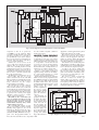

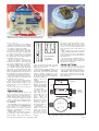
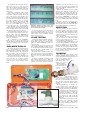


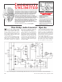

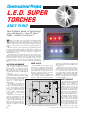


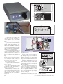


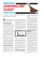
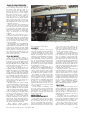


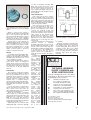


![ManualCover-3Panel10_03 [Converted]](http://vs1.manualzilla.com/store/data/005711777_1-408df82eece155ec198a9b3b174c8b0a-150x150.png)