1
saxo sl
80 -
i n s t r u c t i o n f o r i n s ta l l at i o n
Thefollowingrequirementsapplytothegasconnection:
- useagaspipewiththecorrectdimensions,sothatnopressurelosscanoccur;
- thegastapshouldhavetheCEmarking;
- youshouldalwaysbeabletoreachthegastap.
6.4Placingtheappliance
Placetheapplianceasfollows:
Caution - make sure that combustible objects and/or materials have a distance from the appliance of at least 500 mm;
- Donotmakeanychangestotheappliance.
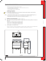
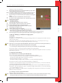
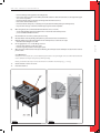
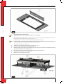
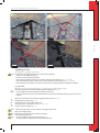
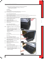
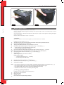
!Caution - Take the build-in height of the appliance into account; it depends on the length of the adjustable legs (see fig. 1).
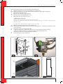
Ifnecessary,thelegscanbeshortened.Theymustbefixedwithself-boringparkers(seefig. 2);
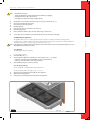
- Takethedepthoftheapplianceintoaccount(seefig. 3);(498mmminimum).
-
-
-
-
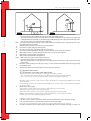
160mmforawallductthroughincombustiblematerial;
Ø
Ø250mmforawallductthroughcombustiblematerial;
Ø160mmforaroofductthroughincombustiblematerial;
Ø250mmforaroofductthroughcombustiblematerial.
Place the appliance on its destined location.
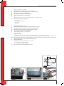
Thegascontrolblockismountedundertheappliance,attheburnerplate.Itshouldbemadelooseandplacedinthe
controlboxatalaterstage.Forplacingthegascontrolblockinthecontrolbox,seesection6.7.
150
100
493,5
257
824,5
380
589
50
16
125
16
790
344
Max 1200
450
➠
English
Determine the location of the appliance.
Provide a gas connection at the location. For details, see section 6.3.
Make a duct for the flue gas discharge/combustion air supply system with the following diameters. For details, see
section 6.5.
Min 732
➠
➠
➠
38c-1258
Fig. 1
Saxo SL80
5 UK