1
Model 1011 Installation and Operation Manual
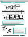
System Mounting
IMPORTANT NOTES
Mounting FM & PM Configurations
The system should be mounted at EYE LEVEL.
1. Carefully read the HELPFUL HINTS located below.
Care must be taken to ensure the system and all protruding
components are clear of all enclosure accesses (doors and
covers) and conduit, pipe, tubing or cable entries.
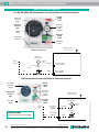
2. Transfer panel cutout pattern to the intended surface.
LH, RH, TM and BM configurations are intended for
mounting adjacent to the protected enclosure.
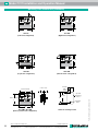
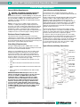
Determine the mounting configuration for your application
using the diagrams on page 8.
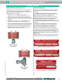
Remove and save the manila envelope (containing the
enclosure warning nameplate) which may be taped to the
System mounting bracket.
Although all systems are factory tested and calibrated, we
strongly suggest a bench test of basic functions prior to
installation.
Mounting LH, RH, TM, & BM Configurations
1. Determine the mounting configuration for your application
using the diagrams on page 8.
2. Secure the system mounting bracket to the appropriate
edge of the system mounting plate using the hex head set
screws provided with the system.
3 . Transfer hole pattern of system mounting bracket to
intended surface.
3. Check for obstructions which could prohibit bolt fastening
or system pneumatic connections.
4. Cut panel cutout pattern on the intended surface.
5. Deburr all cutout surfaces.
6. Secure system to enclosure using SMK-4, or equivalent 1/4" x 3/4" stainless steel nuts, bolts, mounting clips and
lock washers.
HELPFUL HINTS
FM and PM configurations are designed to mount through
a panel cutout one (1) inch smaller than the overall height
and width of the system mounting plate, using clips and
fasteners provided with the SMK -4 mounting kit. This
design feature eliminates the need to drill the system
mounting bolt holes in the protected enclosure.
FM configurations are intended for mounting adjacent to
the protected enclosure.
PM configurations are intended for mounting through a
cutout in the protected enclosure surface.
4. Check for obstructions hindering bolt fastening, drill and
ream the mounting holes before mounting the system.
5. Secure the system to the enclosure, or other mounting
surface, using the fastening hardware provided.
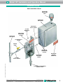
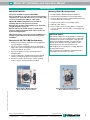
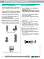
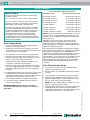
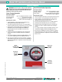
Typical Surface Mounted System
Typical Panel/Frame Mounted System
(Model 1002-LPS-CI-Z-LH shown)
Part No. 512083 Drawing No. 129-0205a 03/09
(Model 1002-LPS-CI-Z-LH shown)
Subject to modifications without notice
Pepperl+Fuchs Group
USA: +1 330 486 0002
www.pepperl-fuchs.com
[email protected]
Germany: +49 621 776 2222
[email protected]
Copyright Pepperl+Fuchs
Singapore: +65 6779 9091
[email protected]
7