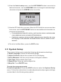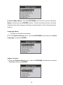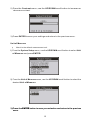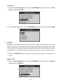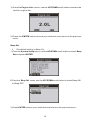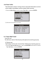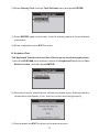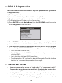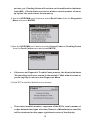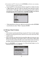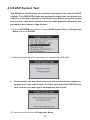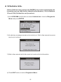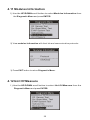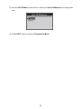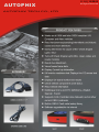
1
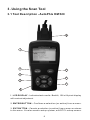
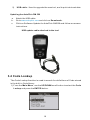
www . autophix . com
Table of Contents
1. Safety Precautions and Warnings . . . . . . . . . . . . . . . . . . . . . . . . . . . . . . 2
2. General Information . . . . . . . . . . . . . . . . . . . . . . . . . . . . . . . . . . . . . . . . 3
2.1 On-Board Diagnostics (OBD) II. . . . . . . . . . . . . . . . . . . . . . . . . . . . . 3
2.2 Diagnostic Trouble Codes (DTCs) .. . . . . . . . . . . . . . . . . . . . . . . . . . 3
2.3 Location of the Data Link Connector (DLC) . . . . . . . . . . . . . . . . . . . 4
2.4 OBD II Readiness Monitors . . . . . . . . . . . . . . . . . . . . . . . . . . . . . . . 5
2.5 OBD II Monitor Readiness Status. . . . . . . . . . . . . . . . . . . . . . . . . . . 6
2.6 OBD II Definitions. . . . . . . . . . . . . . . . . . . . . . . . . . . . . . . . . . . . . . . 6
3. Using the Scan Tool . . . . . . . . . . . . . . . . . . . . . . . . . . . . . . . . . . . . . . . . 8
3.1 Tool Description OM520. . . . . . . . . . . . . . . . . . . . . . . . . . . . . . . . . . 8
3.2 Specifications . . . . . . . . . . . . . . . . . . . . . . . . . . . . . . . . . . . . . . . . 9
3.3 Accessories Included . . . . . . . . . . . . . . . . . . . . . . . . . . . . . . . . . . . . 9
3.4 Code Lookup . . . . . . . . . . . . . . . . . . . . . . . . . . . . . . . . . . . . . . . . . . 10
3.5 System Setup . . . . . . . . . . . . . . . . . . . . . . . . . . . . . . . . . . . . . . . . 11
3.6 Tool Info. . . . . . . . . . . . . . . . . . . . . . . . . . . . . . . . . . . . . . . . . . . . 16
3.7 Tool Self - Test . . . . . . . . . . . . . . . . . . . . . . . . . . . . . . . . . . . . . . . 16
4. OBD II Diagnostics . . . . . . . . . . . . . . . . . . . . . . . . . . . . . . . . . . . . . . . . 18
4.1 Read Fault Codes. . . . . . . . . . . . . . . . . . . . . . . . . . . . . . . . . . . . . 18
4.2 Eras Fault Codes .. . . . . . . . . . . . . . . . . . . . . . . . . . . . . . . . . . . . 20
4.3 View Data Stream. . . . . . . . . . . . . . . . . . . . . . . . . . . . . . . . . . . . . 21
4.4 View Freeze Frame . . . . . . . . . . . . . . . . . . . . . . . . . . . . . . . . . . . . . . 24
4.5 I/M Readiness . . . . . . . . . . . . . . . . . . . . . . . . . . . . . . . . . . . . . . . . 24
4.6 Current Trip Info.. . . . . . . . . . . . . . . . . . . . . . . . . . . . . . . . . . . . . . . 25
4.7 O2 Sensor Test. . . . . . . . . . . . . . . . . . . . . . . . . . . . . . . . . . . . . . . . 27
4.8 On-Board Monitor Test . . . . . . . . . . . . . . . . . . . . . . . . . . . . . . . . . . 28
4.9 EVAP System Test. . . . . . . . . . . . . . . . . . . . . . . . . . . . . . . . . . . . . . 30
4.10 Vehicle Info. . . . . . . . . . . . . . . . . . . . . . . . . . . . . . . . . . . . . . . . . . 31
4.11 Modules Information . . . . . . . . . . . . . . . . . . . . . . . . . . . . . . . . . . . 32
4.12 Unit Of Measure .. . . . . . . . . . . . . . . . . . . . . . . . . . . . . . . . . . . . . . 32
5. Warranty and Service . . . . . . . . . . . . . . . . . . . . . . . . . . . . . . . . . . . . . . 34
5.1 Limited One Year Warranty. . . . . . . . . . . . . . . . . . . . . . . . . . . . . . . 34
5.2 Service Procedures . . . . . . . . . . . . . . . . . . . . . . . . . . . . . . . . . . . . . 34
1
1. Safety Precautions and Warnings
To prevent personal injury or dama ge to vehicles and/or the scan tool, read this
instruction manual first and observe the following safety precautions at a
minimum whenever working on a vehicle:
Always perform automotive testing in a safe environment.
Do not attempt to operate or observe the tool while driving a vehicle.
Operating or observing the tool will cause driver distraction and could
cause a fatal accident.
Wear safety eye protection that meets ANSI standards.
Keep cl ot hi ng, hai r, hands , tool s, test equi pm ent , et c. away from al l movi ng or
hot engine parts.
Operate the vehicle in a well ventilated work area: Exhaust gases are
Poisonous.
Put bl oc ks in front of the dr ive wheel s and nev er leav e the ve hi cl e una ttend ed
while running tests.
Use extreme caution when working around the ignition coil, distributor cap,
igni tion wi res and sp ar k pl ugs . Thes e co mpon ent s cr eat e haz ar dou s vo ltage s
when the engine is running.
Pu t the transmi ssion in PARK (for automat ic transmi ssion) or NEU TR AL (for
manual transmission) and make sure the parking brake is engaged.
Keep a fire ex tingu ish er su itabl e for gas ol ine/ ch emi ca l/el ec trica l fires nea rby.
Don 't con ne ct or di scon ne ct an y tes t eq ui pme nt whi le the ign ition is on or the
engine is running.
Keep the scan tool dry, clean, free from oil/water or grease. Use a mild
detergent on a clean cloth to clean the outside of the scan tool, when
Necessary.
2
2. General Information
2.1 On-Board Diagnostics (OBD) II
The first generation of On-Board Diagnostics (called OBD I) was
developed by the California Air Resources Board (CARB) and
implemented in 1988 to monitor some of the emission control components
on vehicles. As technology evolved and the desire to improve the OnBoard Diagnostic system increased, a new generation of On-Board
Diagnostic system was developed. This second generation of On-Board
Diagnostic regulations is called "OBD II".
The OBD II system is designed to monitor emission control systems and
key engine components by performing either continuous or periodic tests
of specific components and vehicle conditions. When a problem is
detected, the OBD II system turns on a warning lamp (MIL) on the vehicle
instrument panel to alert the driver typically by the phrase “Check Engine”
or “Service Engine Soon”. The system will also store important information
about the detected malfunction so that a technician can accurately find and
fix the problem. Here below follow three pieces of such valuable
Information:
1) Whether the Malfunction Indicator Light (MIL) is commanded 'on' or
'Off';
2) Which, if any, Diagnostic Trouble Codes (DTCs) are stored;
3) Readiness Monitor status.
2.2 Diagnostic Trouble Codes (DTCs)
OBD II Diagnostic Trouble Codes are codes that are stored by the onboard computer diagnostic system in response to a problem found in the
vehicle. These codes identify a particular problem area and are intended to
provide you with a guide as to where a fault might be occurring within a
vehicle. OBD II Diagnostic Trouble Codes consist of a five-digit
alphanumeric code. The first character, a letter, identifies which control
system sets the code. The other four characters, all numbers, provide
additional information on where the DTC originated and the operating
conditions that caused it to be set. Below is an example to illustrate the
structure of the digits:
3
DTC Example
P0520
Systems
B = Body
C = Chassis
P = Powertrain
U = Network
Code Type
Generic (SAE):
P0
B0
C0
U0
Manufacturer Specific:
P1, P2
B1, B2
C1, C2
U1, U2
Last two digits identify individual
component within the system
Sub-systems
1 = Fuel and air metering
2 = Fuel and air metering
3 = Ignition system or engine misfire
4 = Auxiliary emissions controls
5 = Vehicle speed control and idle controls
6 = Computer output circuits
7 = Transmission controls
Figure 1-2: Explanation of a diagnostic trouble code.
2.3 Location of the Data Link Connector (DLC)
The DLC (Data Link Connector or Diagnostic Link Connector) is the
standardized 16-cavity connector where diagnostic scan tools interface
with the vehicle's on-board computer. The DLC is usually located 12
inches from the center of the instrument panel (dash), under or around the
driver's side for most vehicles. If the Data Link Connector is not located
under the dashboard, a label should be there revealing its location. For
some Asian and European vehicles, the DLC is located behind the ashtray
and the ashtray must be removed to access the connector. If the DLC
cannot be found, refer to the vehicle's service manual for the location.
Figure 1-3: The DLC connector (left) can be found in the area of
the car interior seen at right (black arrow).
4
2.4 OBD II Readiness Monitors
Readiness Monitors are indicators used to find out if all of the emissions
components have been evaluated by the OBD II system. They are running
periodic tests on specific systems and components to ensure that they are
performing within allowable limits.
currently, there are eleven OBD II Readiness Monitors (or l/M Monitors)
defined by the U.S. Environmental Protection Agency (EPA). Not all
monitors are supported by all vehicles and the exact number of monitors in
any vehicle depends on the motor vehicle manufacturer ’s emissions
control strategy.
Comtinuous Monitors – Some of the vehicle components or systems are
continuously tested by the vehicle’s OBD II system, while others are tested
only under specific vehicle operating conditions. The continuously
monitored components listed below are always ready:
1. Misfire
2. Fuel System
3. Comprehensive Components (CCM)
Once the vehicle is running, the OBD II system is continuously checking
the above components, monitoring key engine sensors, watching for
engine misfire, and monitoring fuel demands.
Non-Continuous Monitors – Unlike the continuous monitors, many
emissions and engine system components require the vehicle to be
operated under specific conditions before the monitor is ready. These
monitors are termed non-continuous monitors and are listed below:
1. EG R Syst em - exha ust Gas Reci rcul at ion for reduci ng gr eenhouse gase s.
2. O2 Sensors - monitor and adjust air/fuel mixture.
3. Catalyst - reduces exhaust emissions.
4. Evaporative System - monitors the integrity of the fuel tank system.
5. O2 Sensor Heater - brings O2 sensor to correct operating temp erature.
6. Secondary air - reduces exhaust emissions.
7. Heated Catalyst - brings catalyst to correct operating temperature.
8. A/C system - monitors system for freon leaks.
5
2.5 OBD II Monitor Readiness Status
OBD II systems must indicate whether or not the vehicle’s PCM’s
monitoring has completed testing on each emission component.
Components that have been OBD II tested will be reported as “OK”. The
purpose of recording readiness status is to allow inspectors to determine if
the vehicle’s OBDII system has tested all the emissions systems. This is
handy to know before bringing vehicle to a state emissions testing facility.
The powertrain control module (PCM) sets a monitor to “OK” after an
appropriate drive cycle has been performed. The drive cycle that enables a
Monitor and sets readiness codes to “OK” varies for each individual
monitor. Oncce a monitor is set as “OK”, it will remain in this state. A
number of factors, including erasing of diagnostic trouble codes (DTCs)
with a code reader or a disconnected battery, can result in Readiness
Monitors being set to “INC” (incomplete). Since the three continuous
monitors are constantly evaluating, they will be reported as “OK” all of the
time. As long as there are no DTCs stored in memory, the vehicle is
running in accordance with the OBD II guidelines. If testing of a particular
supportes non-continuous monitor has not been completed or not tested,
the monitor status will be reported as “INC” (incomplete).
In order for the OBD monitor system to become ready, the vehicle should
be driven under a variety of normal operating conditions. These operating
conditions may include a mix of highway driving and stop and go, city type
driving, and at least one overnight-off period. For specific information on
getting your vehicle’s OBD monitor system ready, please consult your
vehicle owner’s manual.
2.6 OBD II Definitions
Powertrain Control Module (PCM) – the OBD II terminology for the onboard computer that controls the engine and the drive train.
Malfunction Indicator Light (MIL) – Malfunction Indicator Light (Service
Engine Soon, Check Engine) is a term used for the light on the instrument
panel. It is to alert the driver and/or the repair technician that there is a
problem with one or more of vehicle’s systems and may cause emissions
to exceed federal standards. If the MIL illuminates with a steady light, it
indicates that a problem has been detected and the vehicle should be
serviced as soon as possible. Under certain conditions, the dashboard
light will blink or flash. This indicates a severe problem and flashing is
6
intended to discourage vehicle operation. The vehicle onboard diagnostic
system can not turn the MIL off until necessary repairs are completed or
the condition no longer exists.
DTC – Diagnostic Trouble Codes (DTC) these identify which section of the
emission control system has malfunctioned.
Enabling Criteria – Also termed Enabling Conditions. They are the
vehicle-specific events of conditions that must occur within the engine
before the various monitors will set, or run. Some monitors require the
vehicle to follow a prescribed “drive cycle” routine as part of the enabling
criteria. Drive cycles vary among vehicles and for each monitor in any
particular vehicle.
OBD II Drive Cycle – A specific mode of vehicle operation that provides
conditions required to set all the readiness monitors applicable to the
vehicle to the “ready” condition. The purpose of completing an OBD II drive
cycle is to force the vehicle to run its onboard diagnostics. Some form of a
drive cycle needs to be performed after DTCs have been erased from the
PCM’s memory or after the battery has been disconnected. Running
through a vehicle’s complete drive cycle will “set” the readiness monitors
so that future faults can be detected. Drive cycles vary depending on the
vehicle and the monitor that needs to be reset. For vehicle specific drive
cycle, consult the vehicle’s Owner’s Manual.
Freeze Frame Data – When an emissions related fault occurs, the OBD II
system not only sets a code, but also records a snapshot of the vehicle
operating parameters to help in identifying the problem. This set of values
is referred to as Freeze Frame Date and may include important engine
parameters such as engine RPM, vehicle speed, air flow, engine load, fuel
pressure, fuel trim value, engine coolant temperature, ignition timing
advance, or closed loop status.
7
3. Using the Scan Tool
3.1 Tool Description - AutoPhix OM 520
9
1
2
3
6
5
4
7
8
1. LCD DISPLAY – Indicates test results. Backlit, 128 x 64 pixel display
with contrast adjustment.
2. ENTER BUTTON – Confirms a selection (or action) from a menu.
3. EXIT BUTTON – Cancels a selection (or action) from a menu or returns
to the menu. It is also used to setup system, exit DTC Lookup screen.
8
4. LEFT SCROLL BUTTON – When looking up DTC definitions, moves
to previous character and views additional information on previous screens
if DTC definition covers more than one screen; deselect all marked
PID data when viewing or recording customized live data list; updates
DTC library when pressed.
5. RIGHT SCROLL BUTTON – When looking up DTC definitions,
moves to next character and views additional information on next screens
if DTC definition covers more than one screen; selects/deselects PID data.
6. UP SCROLL BUTTON – Moves up through menu and submenu
items in menu mode. When more than one screen of data is retrieved,
moves up through the current screen to the previous screens for additional
data.
7. DOWN SCROLL BUTTON – Moves down through menu and
submenu items in menu mode. When more than one screen of data is
retrieved, moves down through the current screen to next screens for
additional data.
8. HELP BUTTON – Provides help information when pressed.
9. OBD II CONNECTOR – Connects the scan tool to the vehicle’s Data
Link Connector (DLC).
3.2 Specifications
1)
Display: Backlit, 128 × 64 pixel display with contrast adjustment
2)
Operating Temperature: 0 to 60°C (32 to 140 F°)
3)
4)
Storage Temperature: -20 to 70°C (-4 to 158 F°)
External Power: 8.0 to 18.0 V power provided via vehicle battery
5)
Dimensions:
Height
Width
30 mm (1.16”)
88 mm (3.45”)
NW: 0.48kg (1.06lb), GW: 0.62kg (1.36lb)
Length
166 mm (6.48”)
6)
3.3 Accessories Included
1)
OB D II cable – Provides powe r to tool and commu nicates betwe en tool and
vehicle.
9
2)
USB cable – Used to upgrade the scan tool, and to print retrieved data.
Updating the AutoPhix OM 520
a.
Attach the USB cable.
b.
Go to www.autophix.com and click on Downloads.
c.
Click on Software Update for AutoPhix OM520 and follow on-screen
instructions.
USB update cable attached to the tool.
3.4 Code Lookup
The Code Lookup function is used to search for definitions of Code stored
in the built-in Code library.
1) From the Main Menu, use the UP/DOWN scroll button to select the Code
Lookup and press the ENTER button.
10
2) From the Code Lookup menu, use the LEFT/RIGHT button to move to the
desired character, use the UP/DOWN button to change the selected digit/
character and press the ENTER button to confirm.
3) View the DTC definition on screen. Wh en the DTC definition covers mo re than
one screen, use the LEFT/RIGHT button to view additional information on
previous/next screen(s).
For manufacturer specific codes, you'll need to select a vehicle make
on an additional screen to look for DTC definitions.
If definition could not be found (SAE or Manufacturer Specific), the scan
tool displays "DTC definition not found! Please refer to vehicle service"
manual!"
4) To exit to the Main Menu, press the EXIT button.
3.5 System Setup
The scan tool allows you to make the following adjustments and settings:
1) Select Language: Selects the desired language.
2) Adjust Contrast: Adjusts the contrast of the LCD display.
3) Unit of Measure: Sets the unit of measure to English or Metric.
4) Fuel Type: Select vehicle Fuel Type.
5) Engine Liter: Setup up vehicle engine liter.
6) Beep Set: Turns ON/OFF beep.
To enter the setup menu mode
From the keyboard: Press the EXIT button to enter the System Setup
menu. Follow the instructions to make adjustments and program settings
as described in the following setup options.
11
From the Main Menu: Use the UP/DOWN scroll button to select System
Setup, and press the ENTER button. Follow the instructions to make
adjustments and program settings as described in the following setup
options.
Language Setup
English is the default language.
From the System Setup menu, use the UP/DOWN scroll button to select
Language, and press ENTER.
Adjust Contrast
1) From the System Setup menu, use the UP/DOWN scroll button to select
Contrast, and press ENTER.
12
2) From the Contrast menu, use the UP/DOWN scroll button to increase or
decrease contrast.
3) Press ENTER to save your settings and return to the previous menu.
Unit of Measure
Metric is the default measurement unit.
1) From the System Setup menu, use the UP/DOWN scroll button to select Unit
of Measure and press ENTER.
2) From the Unit of Measure me nu, use the UP/DOWN scroll button to select the
desired Unit of Measure.
3) Press the ENTER button to save your selection and return to the previous
menu.
13
Fuel Type
1) From the System Setup me nu, use the UP/DOWN scroll button to select Fuel
Type and press ENTER.
2) Fr om the Fuel Type menu, use the UP/ DOWN scr ol l but ton to sel ect the Fuel Type .
● NOTICE
DIESEL1 and DIESEL2 do not refer to different types of diesel fuel. They only
affect the way fuel consumption is computed and are selected based on the
way the vehicle computer reports its sensor information. Most diesel vehicles
use DIESEL1. Do the following to determine which your diesel vehicle uses.
3) Press the ENTER button to save your selection and return to the previous
menu.
Engine Liter
1) Fr om the Sy stem Se tup men u, use the UP/ DOWN scroll button to select En gi ne
Liter and press ENTER.
14
2) From the Engine Liter menu, use the UP/DOWN scroll button to select the
vechile engine liter .
3) Press the ENTER button to save your selection and return to the previous
menu.
Beep Set
The default setting is Beep On.
1) Form the System Se tup me nu, use the UP/DOWN scroll button to select Beep
Set and press ENTER.
2) From the 'Beep Se t' menu, use the UP/ DOWN scroll button to select Beep ON
or Beep OFF.
3) Press ENTER to save your selection and return to the previous menu.
15
3.6 Tool Info.
Tool Information allows viewing of some important information such as
serial number and software version number of the scanner.
1) From the Main Menu, scroll to select Tool Info. and press ENTER.
2) View tool information on screen.
3.7 Tool Self-test
Tool Self-test
The Self-test checks if the display and keyboard are working properly.
A. Display test
The Display Test function checks if the LCD display is working properly.
1) From the System Setup menu, use the UP/DOWN scroll button to select
Tool Self-test, and press ENTER.
16
2) Select Display Test from the Tool Self-test menu and press ENTER.
3) Press ENTER again to start test. Look for missing spots in the solid black
characters.
4) When completed, press EXIT to return.
B. Keyboard Test
The Keyboard Test function verifies if the keys are functioning properly.
1) Use the UP/DOWN scroll button to select the Keyboard Test from the Tool
Self-test menu, and then press ENTER.
2) Press any key to start the test. When you press a key, the key name is
observed on the display. If not, then key is not functioning properly.
3) Double press the EXIT to return to the previous menu.
17
4. OBD II Diagnostics
CAUTION: Don't connect or disconnect any test equipment with ignition on
or engine running.
1) Turn the ignition off.
2) Locate the vehicle's 16-pin Data Link Connector (DLC).
3) Plug the scan tool cable connector into the vehicle's DLC.
4) Turn the ignition on. Engine can be off or running.
5) Press ENTER to enter Main Menu. Use the UP/DOWN scroll button to
select Diagnostics from the menu.
6) Press ENTER to confirm. A sequence of messages displaying the OBD II
protocols will be observed on the display until the vehicle protocol is detected.
If the scan tool fails to communicate with the vehicle's ECU (Engine
Control Unit), a "LINKING ERROR!" message shows up on the display.
-
Verify that the ignition is ON;
Check if the scan tool's OBD II connector is securely connected to the
-
Verify that the vehicle is OBD II compliant;
Turn the ignition 'off' and wait for about 10 seconds. Turn the ignition
vehicle's DLC;
back to 'on' and repeat the procedure from step 5.
4.1 Read Fault codes
Stored codes are also known as "hard codes" or "permanent codes".
These codes cause the control module to illuminate the malfunction
indicator lamp (MIL) when an emission-related fault occurs.
Pending Co des are also referred to as "maturing codes" or "continuous
monitor codes". They indicate problems that the control module has
detected during the current or last driving cycle, but are not considered
18
serious, yet. Pending Codes will not turn on the malfunction indicator
lamp (MIL). If the fault does not occur within a certain number of warmup cycles, the code clears from memory.
1) Use the UP/DOWN scroll button to select Read Codes from the Diagnostic
Menu and press ENTER.
2) Use the UP/DOWN scroll button to select Stored Codes or Pending Codes
from the Fault Codes menu and press ENTER.
If there are no Diagnostic Trouble Codes present, the display indicates
"No (pending) codes are stored in the module!" Wait a few seconds or
press any key to return to the Diagnostic Menu.
3) View DTCs and their definitions on screen.
The control module number, sequence of the DTCs, total number of
codes detected and type of codes (Generic of Manufacturer specific)
will be observed on the upper right hand corner of the display.
19
4) If more than one DTC is found, use the UP/DOWN scroll button, as necessary,
until all the codes have been viewed.
If retrieved DTCs contain any ma nufacturer specific or enhanced codes,
a "Manufacturer specific codes are found! Press any key to select
vehicle make!" message comes up prompting you to select vehicle
manufacturer to view DTC definitions. Use the UP/DOWN scroll button
to select manufacturer and then press ENTER to confirm.
If the manufacturer for your vehicle is not listed, use the UP/DOWN
scroll button to select "Other" and press ENTER.
4.2 Erase Fault Codes
Notes:
This function is performe d wi th key on engine off . Do not start the engine.
Before performing this function, make sure to retrieve and record the
trouble codes.
After clearing, you should retrieve trouble codes once more or turn
ignition on and retrieve codes again. If there is still some trouble codes
for hard troubles, please find the reason caused the trouble code firstly,
and then solve the problem. Now, the trouble codes can be erased.
1) Use the UP/DOWN scroll buttons to select Erase Fault Codes from the
Diagnostic Menu and press ENTER.
20
2) A warning message comes up asking for your confirmation.
3) Press ENTER to confirm.
If the codes are cleared successfully, an "Erase Done!" confirmation
message is displayed.
If the codes are not cleared, then an "Erase Failure. Turn Key on with
Engine off!" message is displayed.
4.3 View Data Stream
The OBD II Scan Tool is a special diagnostic tool that communicates
with the vehicle's computer. The Scan Tool lets you view "real-time"
Live Data. This information includes values (volts, rpm, temperature,
speed etc.) and system status information (open loop, closed loop, fuel
system status, etc.) generated by the various vehicle sensors, switches
and actuators.
21
Supported Data List
1) Use the UP/DOWN scroll buttons to select Supported Data List from the
View Data Stream and press ENTER.
2) To view live PIDs on the screen. Use the UP/DOWN scroll button for more
PIDs if an
or
arrow appears on the screen.
If you want to view the full name of the highlighted PID, press the Help
button.
If the "G" icon appears wh en a PID is highlighted, graphic informa tion is
available. Press ENTER to view.
3) Press EXIT to return to previous menu.
22
Custom Data List
1) To view customized PID data, use the UP/DOWN scroll button to select
Custom Data Set from the View Data Stream menu and press ENTER.
2) Observe on-screen instructions.
3) Use RIGHT button to select/deselect data parameters. Selected parameters
are marked with solid squares. Press ENTER to confirm.
If you want to deselect all marked items, press LEFT button.
4) Press ENTER to view selected PIDs on screen.
23
5) Use the EXIT button to return to View Da ta St ream me nu.
4.4 View Freeze Frame
When an em issi on-r el at ed faul t occurs, cer tai n vehi cl e cond itions ar e recorded
by the on -bo ar d co mput er. Th is inf or mat ion is ref er red to as free ze frame da ta.
View Freeze Data is a snapshot of the operating conditions at the time of
an emission-related fault.
if DTCs wer e er as ed , View Fr ee ze Dat a may no t be st or ed in ve hi cl e memor y
depending on vehicle.
Select [View Freeze Frame], the screen will display the interface as shown
below:
Use the UP/DOWN scroll button for more PIDs if an
on the screen. Press EXIT to return to Main Menu.
or
arrow appears
4.5 I/M Readiness
I/M refers to Inspection and Maintenance, that is legislated by the
Government to meet federal clean-air standards. I/M Readiness
indicates whether or not the varous emissions-related systems on the
vehicle are operating properly and are ready for Inspection and
Maintenance testing.
24
The purpose of the I/M Readiness Monitor Status is to indicate which of
the vehicle's Monitors have run and completed their diagnosis and
testing (as described in 2.5), and which ones have not yet run and
completed testing and diagnosis of their designated sections of the
vehicle's emissions system.
The I/M Readiness Monitor Status function also can be used (after repair
of a fault has been performed) to confirm that the repair has been
performed correctly, and/or to check for Monitor Run Status.
Select [I/M Readiness Test] and Press [ENTER], the screen will display
the interface as shown below:
Press EXIT return to the Diagnostic Menu.
4.6 Current Trip Info.
This Function can display some Information about the current trip. The
following information can be displayed:
1. Fuel Consumption
2. Fuel Economy
3. AVG Economy
4. Fuel Used
5. Speed
6. AVG Speed
7. Distance
8. Running Time
Note:
Do not try to make any adjustment While driving.
Do not route the cable in a manner which would interfere with the operation
of the vehicle controls.
When first use this function you should setup the Fuel type and Engine
liter of your vehicle. (in System Setup menu)
25
1) Use the UP/ DOW N scrol l bu tton to sel ec t Cur ren t Trip Inf o. from the Di ag nos tic
Menu and press ENTER.
2) A message comes up asking for your confirmation.
3) Press ENTER display the current trip information as following.
26
4) Press EXIT setup up the Fuel Type and Engine Liter.
5) Press EXIT return the trip information View. If you want the Change Unit for
Trip information, you can ENTER Diagnostic Menu Set up the Unit of
Measure.
4.7 O2 Sensor Test
OBD II regulations set by the SAE require that relevant vehicles monitor
and test the oxygen (O2) sensors to identify problems related to fuel
efficiency and vehicle emissions. These tests are not on-demand tests and
they are done automatically when engine operating conditions are within
specified limits. These test results are saved in the on-board computer's
memory.
The O2 Sensor Test function allows retrieval and viewing of O2 sensor
monitor test results for the most recently performed tests from the
vehicle's on-board computer.
The O2 Sensor Test function is not supported by vehicles which
communicate using a controller area network (CAN). For O2 Sensor Test
results of CAN-equipped vehicles, see chapter "On-Board Mon. Test".
27
1) Use the UP/DOWN scroll button to select O2 Sensor Test from Diagnostic
Menu and press ENTER.
2) Use the UP/DOWN scroll button to select O2 sensor from O2 Sensor Test
menu and press ENTER.
3) View test results of the selected O2 sensor.
4) Press EXIT to return to the previous menu.
4.8 On-Board Monitor Test
The On-Board Monitor Test is useful after servicing or after erasing a
vehicle's control module memory. The On-Board Monitor Test for non-CANequipped vehicles retrieves and displays test results for emission-related
28
powertrain components and systems that are not continuously monitored.
The On-Board Monitor Test for CAN-equipped vehicles retrieves and
displays test results for emission-related powertrain components and
systems that are and are not continuously monitored. Test and component
IDs are determined by the vehicle manufacturer.
1) Use the UP/DOWN scroll button to select On-Board Mon. Test from
Diagnostic Menu and press ENTER.
2) From On-Board Mon. Test menu, use the UP/DOWN scroll button to select a
test to view and press ENTER.
3) View test data on screen.
4) Press EXIT to return to the previous menus.
29
4.9 EVAP System Test
The EVAP test function lets you initiate a leak test for the vehicle's EVAP
system. The OBD BOOK does not perform the leak test, but signals to
vehicle's on-board computer to initiate the test. Before using the system
test function, refer to the vehicle's service repair manual to determine the
procedures necessary to stop the test.
1) Use the UP/DOWN scroll button to select EVAP System Test from Diagnostic
Menu and press ENTER.
2) Wait a few seconds while the scan tool validates the PID MAP.
●
Some vehicles do not allow scan tools to control vehicle systems or
comp onents. If the vehicle under test does not support the EVAP System
Test, an advisory message is displayed on the screen.
3) Press any key to return to Diagnostic Menu.
30
4.10 Vehicle Info.
Select [Vehicle Info.] and press [ENTER], the screen will display the
formation such as VIN (Vehicle indentification Number), CID (Calibration
ID) and CVN (Calibration verify number).
1) Use UP/DOWN scroll button to select Vehicle Info. from the Diagnostic
Menu and press ENTER.
2) An advisory message comes up to remind you. Wait a few seconds or press
any key to continue.
3) Wait a few seconds while the scan tool reads vehicle information.
4) Press EXIT button to return Diagnostic Menu.
31
4.11 Modules Information
1) Use the UP/DOWN scroll button to select Modules Information from
the Diagnostic Menu and press ENTER.
2) View modules Information with their Ids and communication protocols.
3) Press EXIT button to return Diagnostic Menu.
4.12 Unit Of Measure
1) Use the UP/DOWN scroll button to select Unit Of Measure from the
Diagnostic Menu and press ENTER.
32
2) Use the UP/DOWN scroll button to select the Unit Of Measure for diagnostic
test .
3) Press EXIT button to return Diagnostic Menu.
33
5. Warranty and Service
5.1 Limited One Year Warranty
THIS WARRANTY IS EXPRESSLY LIMITED TO PERSONS WHO PURCHASE
AUTOPHIX PRODUCTS FOR PURPOSES OF RESALE OR USE IN THE ORDINARY
COURSE OF THE BUYER'S BUSINESS.
AUTOPHIX electronic product is warranted against defects in materials and
workmanship for one year (12 months) from date of delivery to the user.
This warranty does not cover any part that has been abused, altered, used for a
pur pos e ot her than for whi ch it was int end ed, or us ed in a mann er inc ons ist ent wi th
inst ruct ions regar di ng use. The excl usi ve rem edy for any aut om ot ive met er found to
be defective is repair or replaceme nt, and AUTOPHIX shall not be liable for any
consequential or incidental damages.
Final determination of defects shall be made by AUTOPHIX in accordance with
pr oc ed ur es es tab lishe d by AUT OPHI X. No ag en t, empl oy ee , or rep res en tat ive of
AUTOPHIX has any author ity to bi nd AUTOPHIX to any aff irmat ion, represent at ion,
or warranty concerning AUTOPHIX automo tive me ters, except as stated herein.
5.2 Service Procedures
If you have any questions, please contact your local store, distributor or visit our
website at www. autophix.com .
If it becomes necessary to return the scan tool for repair, contact your local
distributor for more information.
34
V.1.0 | 10/2009
AUTOPHlX
A U TO P H I X T E C H C O . , LT D
All Rights Reserved.