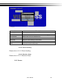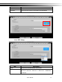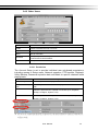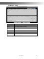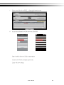
1
V2.2
User Manual
confi
─ DVR ─
Notice: This content is subject to be change without notice.
User Manual
1
WARNING
TO REDUCE THE RISK OF FIRE OR
ELECTRIC SHOCK, DO NOT EXPOSE
THIS APPLIANCE TO RAIN OR MOISTURE.
This symbol is intended to
alert the user to the presence
of unprotected “Dangerous
voltage" within the product's
enclosure that may be strong
enough to cause a risk of
electric shock.
This symbol is intended to
alert the user to the presence
of important operating and
maintenance (servicing) instructions in the literature
accompanying the appliance.
NOTE: This equipment has been tested
and found to comply with the limits for a
class digital device, pursuant to part 15 of
the FCC Rules. These limits are designed
to provide reasonable protection against
harmful interference when the equipment is
operated in a commercial environment.
This equipment generates, uses, and can
radiate radio frequency energy and, if not
installed and used in accordance with the
instruction manual, may cause harmful interference to radio communications. Operation of this equipment in a residential area
is likely to cause harmful interference in
which case the user will be required to
correct the interference at his own expense.
Disposal of Old Electrical & Electronic Equipment (Applicable in the European
Union and other European countries with separate collection systems)
This symbol on the product or on its packaging indicates that this product shall not be treated
as household waste. Instead it shall be handed over to the applicable collection point for the
recycling of electrical and electronic equipment. By ensuring this product is disposed of correctly, you will help prevent potential negative consequences for the environment and human
health, which could otherwise be caused by inappropriate waste handling of this product. The
recycling of materials will help to conserve natural resources. For more detailed information
about recycling of this product, please contact your local city office, your household waste
disposal service or the shop where you purchased the product.
Notice: Ghosting or fractured images may occur on the screen when there is a suddenly surge
or lightning stroke which cause damage on IC in the DVRs.
User Manual
2
Table of Contents
Chapter 1 LIVE OPERATIONS .............................................................................................. 5
Chapter 2 MAIN MENU SETUP ............................................................................................ 9
2-1 Auto Sequential ............................................................................................................ 13
2-2 Backup ......................................................................................................................... 14
2-2.1 Selection............................................................................................................ 14
2-2.2 Select Backup Device...................................................................................... 15
2-3 Configure ...................................................................................................................... 16
2-4 Time Search ................................................................................................................. 17
2-5 System Logs................................................................................................................. 21
2-5.1 Search Criteria ................................................................................................. 22
2-6 PTZ Operation .............................................................................................................. 23
2-7 Zoom ............................................................................................................................ 25
2-8 Shortcut toolbar ............................................................................................................ 26
Chapter 3 CONFIGURATION MENU ................................................................................... 29
3-1 Record Setup ............................................................................................................... 29
3-1.1 Continuous Record ........................................................................................... 30
3-1.1.1 Video Settings ____________________________________________________ 31
3-1.1.2 Event Recording ___________________________________________________ 32
3-1.2 Schedule Recording ......................................................................................... 33
3-1.2.1 Configuration______________________________________________________ 34
3-1.2.2 Holiday Configuration ______________________________________________ 34
3-2 Event Setup .................................................................................................................. 35
3-2.1 Video Loss ........................................................................................................ 35
3-2.1.1 Configuration______________________________________________________ 35
3-2.1.2 Event Handling ____________________________________________________ 36
3-2.1.3 Receiver Setup ____________________________________________________ 36
3-2.2 Motion Detection .............................................................................................. 37
3-2.2.1 Configuration______________________________________________________ 37
3-2.2.1.1 Motion Area Setup _______________________________________________ 37
3-2.2.2 Event Handling ____________________________________________________ 38
3-2.2.3 Receiver Setup ____________________________________________________ 38
3-2.3 Sensor ............................................................................................................... 38
3-2.3.1 Configuration______________________________________________________ 39
3-2.3.2 Event Handling ____________________________________________________ 39
3-2.3.3 Receiver Setup ____________________________________________________ 39
3-2.4 System .............................................................................................................. 39
3-2.4.1 Receiver Setup ____________________________________________________ 40
3-3 Camera Setup .............................................................................................................. 40
3-3.1 PTZ Setup ........................................................................................................ 41
3-4 Account Setup .............................................................................................................. 43
3-4.1 Administrator ..................................................................................................... 43
3-4.2 Other Users ...................................................................................................... 44
3-4.2.1 Permission ________________________________________________________ 44
3-5 Network Setup .............................................................................................................. 45
3-5.1 Networking Setup ............................................................................................. 46
3-5.1.1 DHCP Setup ______________________________________________________ 46
3-5.1.2 Static IP Setup ____________________________________________________ 46
3-5.1.3 PPPoE Setup ______________________________________________________ 47
3-5.1.4 3G Setup _________________________________________________________ 48
3-5.1.5 Bandwidth Limited _________________________________________________ 49
3-5.2 HTTP Setup ...................................................................................................... 50
3-5.3 DDNS Setup ..................................................................................................... 50
3-5.4 NTP Setup ........................................................................................................ 51
3-5.5 Mail Setup ........................................................................................................ 52
User Manual
3
3-5.6 FTP Setup ........................................................................................................... 53
3-6 Storage Setup .............................................................................................................. 54
3-6.1 HDD Setup ....................................................................................................... 54
3-6.2 USB Flash Derive Setup ................................................................................. 55
3-6.3 DVD-RW Setup ................................................................................................ 55
3-7 System Setup ............................................................................................................... 56
3-7.1 Auto Lock ......................................................................................................... 57
3-7.2 Auto Reboot ..................................................................................................... 57
3-7.3 Date/Time Setup............................................................................................... 58
3-7.3.1 Time zone ________________________________________________________ 58
3-7.3.2 Daylight Saving Time Setup ....................................................................................... 58
3-7.3.3 Change Date and Time _____________________________________________ 59
3-7.4 Monitor Setup ................................................................................................... 60
3-7.5 Input Setup ....................................................................................................... 62
3-7.5.1 Remote Control Setup ______________________________________________ 62
3-7.5.2 Panel Setup _______________________________________________________ 63
3-7.5.3 Mouse Setup ______________________________________________________ 63
3-7.5.4 PTZ Keyboard Setup _______________________________________________ 64
3-7.5.5 Touch Screen Setup ________________________________________________ 64
3-7.6 Utility Setup ...................................................................................................... 65
3-7.6.1 Export Configuration _______________________________________________ 66
3-7.6.2 Import Configuration _______________________________________________ 67
3-7.6.3 Reset Configuration ________________________________________________ 68
3-7.6.4 Export Logs ______________________________________________________ 68
3-7.6.5 Clear Logs _______________________________________________________ 69
3-7.6.6 Upgrade Firmware _________________________________________________ 70
3-8 System Information ...................................................................................................... 71
3-8.1 DVR Information ............................................................................................... 71
3-8.2 Network Information ......................................................................................... 71
3-8.3 HDD Information ............................................................................................... 71
3-8.4 S.M.A.R.T Information ...................................................................................... 72
REMOTE SOFTWARE INSTALLATION and SETUP ........................................................... 73
3-9 Application Software Connection ................................................................................. 73
3-10 IE Connection ............................................................................................................. 75
3-11 AP Software and IE Connection Operation ................................................................ 77
3-12 P2P Connection Setup ............................................................................................... 78
User Manual
4
Note: The number of channels, sensors, relays, and split screen, and the resolution in
the following figures are for reference. The actual screen output may be different by different models.
Chapter 1
LIVE OPERATIONS
In the live mode, you may monitor all channels of the DVR, listen to live audio from cameras, and
configure the DVR. The DVR can support 4:3 and 16:9 aspect ratios of the screen layout. There
is a shortcut toolbar on the top of the screen for users to logout, to access system information, to
change screen aspect ratio, to make the DVR window full-screen, and to configure network
stream quality. In the 16:9 mode, there are two major panes, the configuration menu and channel
pane for video of channels. In the 4:3 mode, a user may access the configuration pane by
right-clicking the mouse on the screen splits and a channel status pane will appear when the
mouse cursor moves to the bottom of the screen
HD Series:.
Shortcut toolbar
Configuration
Panel
Shortcut toolbar
16:9 display - Operation screen
Channel Status
Panel
4:3 display - Operation screen
User Manual
5
HHD Series :
Shortcut toolbar
Configuration
Panel
16:9 display - Operation screen
Shortcut toolbar
Channel Status
Panel
4:3 display - Operation screen
User Manual
6
960H Series:
Shortcut toolbar
Configuration
Panel
16:9 display - Operation screen
Shortcut toolbar
Channel Status
Panel
4:3 display - Operation screen
User Manual
7
Table 1-1 Icon description in live mode
Icon
Description
Recording of a channel is activated.
Live audio of a channel is activated.
Live audio of a channel is not activated.
Video signal of a channel is available.
Event recording of a channel is active in this
channel.
Motion detection of a channel is triggered.
Alarm is triggered of a channel. The number of
available alarms depends on models.
Alarm is not triggered of a channel.
The channel video-loss alarm of a channel has
been triggered.
USB device has been detected.
DVD device has been detected.
Network connection is available
Network connection is not available
Displays the current user
Displays the current disk space and usage.
(The figure shows 99% of the disk space has
been used, and 1% is available.). The current disk
temperature is also shown.
Each channel shows the time stamp for local
playback, remote live, remote playback, and
backup-video.
User Manual
8
Chapter 2
MAIN MENU SETUP
To enter the main menu and set up a DVR, log-in account and user password are required.
The default password of the administrator is “123456”. Please check the “Account Setup” for
management of other log-in users.
Table 2-1 Definition of keys of virtual keyboard
Icon
Description
/
Switch between capital letters and lower-case letters.
/
Switch between numbers and letters
Delete the last character。
Enter to verify the password. The DVR shows the setup
menu, if the password is accepted.
Space key
Table 2-2 Available keys on the remote control in the main menu mode
Item
Description
Switch to previous or next options of an item
Switch to different items
MENU
Save setup and back to the LIVE mode
ESC
Back to upper level of menu without saving
ENTER
Enter the menu, or display virtual keyboard
User Manual
9
There are icons within the configuration pane on the live mode to operate different features of the
DVR. The configuration pane is always on the left or right side of the screen in the 16:9 mode and
can to be evoked by right-click in the 4:3 mode.
16:9 display, the main menu is on the right side of the screen
4:3 display, right-click on the screen to evoke the main menu.1
1
Icons may be slightly different by different models
User Manual
10
Table 2- 3 Description of icons
Icon
Description
Evoke the auto sequential menu
Set the backup menu to backup video data from DVR HDD.
Set the configuration menu to access recording settings, event
settings, camera settings, account settings, network settings,
storage settings, system configuration, and information
Set the time search menu to choose a specific time of the recorded
video to playback
Play Back menu
Set the event search menu to access the list of events recorded by
the DVR. The event list will show the event occurrence time, event
category, channel events, and other information.
Set the PTZ mode
Focus Mode *1
Set the Zoom-in function. The DVR supports zoom-in from 2x to 8x
digital zoom
Set image freeze function
User Manual
11
Disable image freeze function
Enable/Disable PIP *2
Switch to single split
Switch to 4-split display
Switch to 9-split display
Switch to 10-split display
Switch to 13-split display
Switch to 16-split display
Switch to 20-split display
Switch to 25-split display
Switch to 32-split display
*1.Maya V2 Series not support focus mode
*2 PIP not Support RHD-813B、RHD-1613B、HHD-2013B & DVR-3213B
User Manual
12
2-1 Auto Sequential
16:9 display
4:3 Display
Item
Description
Interval
The time interval between each channel display
All Channels
The DVR automatically switches between channels with designated
interval. The DVR shows each channel in a single-split mode.
Quad-Screen Division
The DVR automatically switches between channels with designated
interval. The DVR shows channels in 4-split mode.
9-Screen Division
The DVR automatically switches between channels with designated
interval. The DVR shows channels in 9-split mode.
10-Screen Division
The DVR automatically switches between channels with designated
interval. The DVR shows channels in 10-split mode.
16-Screen Division
The DVR automatically switches between channels with designated
interval. The DVR shows channels in 16-split mode.
20-Screen Division
The DVR automatically switches between channels with designated
interval. The DVR shows channels in 20-split mode.
32-Screen Division
The DVR automatically switches between channels with designated
interval. The DVR shows channels in 32-split mode.
User Manual
13
2-2 Backup
User can backup recorded video data of a specified time frame. The DVR can backup video data
to either direct-attached storage, such as DVR or USB drive, or remote folder of a PC.
2-2.1 Selection
Item
Description
From
The start time of video data to be backed up
To
The end time of video data to be backed up
Duration
The time duration of backup file
All
It can select all channels or clear all selected channels to backup
Required Space
Show the size of the backup file
User Manual
14
2-2.2 Select Backup Device
Item
Description
Backup Device
Select target device of backup (USB/DVD-RW/remote folder) 。
Status
The status of target backup device
Free Space
The available space in the target backup device. (not available for
remote folder backup)
Start backup operation.
Backup
Be sure to calculate the size of backup file BEFORE operating
backup.
Do not unplug the USB device or turn off the DVR during the backup process to avoid
unrecoverable error.
User Manual
15
2-3 Configure
Evoke the configuration menu, recording settings, event settings, camera settings, account settings, network settings, storage settings, system configuration,
and information. Please refer to chapter 3 for detail.
User Manual
16
2-4 Time Search
Time search can search for the specific time of recorded data to playback. Note
that dates with recording data are marked with a blue box. System will start
playing video of specified time slot. Calendar will be shown by using mouse to
click on “year” and “month”.
Click “date” to display recording time of that specific date with time bar. You can
change time (hour/minute/second) or click on a specific pint of time bar by
mouse then press “ok”. DVR will playback the recorded data of the specific
time.
Item
Description
Playback button, start playback.
Select playback time by sliding the position of the cursor
to the specified time. The
timeline scale is 24 hours.
The blue chart represents
available video data.
User Manual
17
16:9 Display
Playback configuration
4:3 Display
User Manual
18
Table 2-4 Available keys on the remote control functions in the PLAYBACK mode
Button
Description
ENTER/ MODE
Switch to full screen or multi split display.
MENU /
Turn on/off PAUSE.
PLAY
Playback at normal speed.
/ SLOW
Playback at slower speed. The speed will be slowed to 1/2, 1/4, 1/8
playback speed, by each pressing of the button till the slowest speed.
/
Fast rewind. Each press increases the rewind speed to the next level.
There are six speeds: 2x, 4X, 8X, 16x, 32X and 64X.
/
Fast forward. Each press increases the forward speed to the next level.
There are six speeds: 2x, 4X, 8X, 16x, 32X and 64X.
/
Stop playback.
Table 2-5 the mouse operation under the PLAYBACK mode.
Icon
Description
Stop playback, and go to previous page
Play
Pause
Fast rewind, speed 4x, 8x, 16x, 32x
Fast forward, speed 4x, 8x, 16x, 32x
Slow playback, speed 1/2x, 1/4x, 1/8x
Step playback
Zoom-in display, 2x~8x digital zoom
Full screen display
Quad display
9 screen display
10 screen display
User Manual
19
16 screen display
20 screen display
25 screen display
32 screen display
If you want to monitor single channel, please double-click the preferred channel.
16:9 Display
4:3 Display
P.S Can drag a small window
User Manual
20
2-5 System Logs
The DVR logs events automatically. The event list shows the logged events,
event type, event detail, event filter (criteria), and page number of the event list.
If the event video is logged, there is a gray video symbol "►" on the left of the
event. Move the cursor to event line and press "ENTER", or double-click mouse
button, DVR playback this record video related to the event.
Note: If the hard disk is not installed or has not started recording, the DVR will produce
the event list, but the user cannot playback the video of a specific event by clicking the
event.
Item
Criteria
Description
Set the conditions for the event search
Slide the slider to choose a page of the event list. The right numbers will show the corresponding page number
Press left and right arrow keys or enter the page number directly. It
will go to the select event page.
Refresh the event list.
User Manual
21
2-5.1 Search Criteria
The number of event is up to thousands, therefore, to set "search criteria" to
facilitate rapid classification of events. If the checkbox of start time and end time
is checked, the event list will only display the events within the specific time slot.
If the user unchecks some events and press the "OK ", the lists will only shows
checked events. If you uncheck the channels, the event list will filter out unchecked the channels.
User Manual
22
2-6 PTZ Operation
Set up the camera PTZ settings in advance (refer to 3-3.1). Enter the PTZ configuration page, PTZ control panel displays the camera PTZ setting. There is a
red cross on the center of the screen. Move the mouse to the Red Cross and
hold down the left mouse button to the preferred location of the screen. The
DVR will move the camera to the preferred place by placing the preferred place
to the center of the screen. On the screen to move in any direction. It can control the PTZ camera in the direction.
PTZ Configuration
Rotate video function use only remote connection
16:9 Display
User Manual
23
4:3 Mode PTZ configuration
Table 2-6 Function description
Item
Description
ZOOM. Press + / - or move the slider to adjust the zoom
level.
FOCUS. Press + / - or move the slider adjust the PTZ focus
IRIS. Press + / - or move the slider to adjust the PTZ iris
Press left and right arrow keys to move the camera to the
preset locations, and then press
location to default point.
to set current camera
Press left and right arrow keys to move the camera to the
preset locations, and then press
era to next preset point.
Rotate Video
to change the cam-
Make the display upside down
User Manual
24
2-7 Zoom
In the digital zoom mode, users may use the mouse to move the red rectangle of
the zoom area.
16:9 display zoom
4:3 display zoom
P.S Can drag a small window
Item
Description
Zoom-in the area specified by the red rectangle.
Zoom-out the area specified by the red rectangle.
Exit zoom mode
User Manual
25
2-8 Shortcut toolbar
Real-time monitoring mode, move your mouse over the window function column
appears above its fast operation
ICON
Description
User login / logout: Auto lock is used.
System Information: The host model, version, IP location, MAC values and hard
disk information.
Wide screen switching: Switch 4:3 / 16:9 monitor display.
Screenshot.
Turn on / off recording.
Full screen.
Options: Change the PC side screen shots, video storage path.
Network Video Quality: You can follow the PC network bandwidth, adjust the
image transfer traffic.
Displacement Windows settings.
Relays. The user can control the behavior of the relay on the DVR.
※ recording function, full-screen, options, image quality network for remote use of
these four functions
※ screenshots, video features, options, these three features are only available in
"iWatchDVR" use, IE 7/8/9 NOT support
User Manual
26
2-8.1 network image quality
Option
Low Quality Single Image
Low quality
High-quality
High-quality
Description
Low quality static mode: insufficient bandwidth used for one second about
running 1 ~ 2FPS.
Low quality Dynamic mode: According to the DVR recording settings.
High-definition single image under static mode: insufficient bandwidth to
use for one second about running 1 ~ 2FPS.
High-definition Dynamic mode: According to the DVR recording settings.
※ image fluency: To all actual field-based network environment
2-8.2 Preference
User Manual
27
2-8.3 Popup Setup
Item
Description
Event
Prompt window displays the channel status。
OSD
Display time, HDD status, channel information, channel border.
2-8.4 Relay Setup
Option
Relay 1 ~ 4
Functional
Description
Relay
J Series x1, N Series x2, B Series x4.
open, close, automatically
User Manual
28
Chapter 3
CONFIGURATION MENU
PS. The initialization of new-installed HD is required before recording, please refer to “UTILITY
SETUP” for detail.
3-1 Record Setup
Item
Record Mode
Description
Continuous Record/ Schedule Record/ Stop Record
User Manual
29
3-1.1 Continuous Record
Item
Description
Click
Video
Record
Resolution
icon, it will go to the video setting menu of this
channel (below). In settings menu, press
to save, press
go back to the original video settings menu *1
to
Enable / Disable recording for this channel
Recording resolution selection *2
FPS
Select recording frame rate, from 1 to 30
Quality
Recording quality, from 10 to 100. The larger number means the
better quality
Audio
Enable / Disable recording audio
Note 1: Channel Source is "HD signal" no function
User Manual
30
3-1.1.1 Video Settings
16:9 display video settings
4:3 display video settings
Item
Description
Sharpness
Adjust sharpness from 0 to 255
Brightness
Adjust brightness from 0 to 255
Contrast
Adjust contrast from 0 to 255
Saturation
Adjust saturation from 0 to 255
Hue
Adjust hue from 0 to 255
Volume
Adjust volume from 0 to 255
User Manual
31
3-1.1.2 Event Recording
Item
Description
Record
Enable / Disable recording of a channel
Resolution
Recording resolution selection *2
FPS
Select recording frame rate from 1 to 30
Quality
Recording quality from 10 to 100. The larger number means the
better quality
Pre-Alarm
Set the record seconds before the event, from 0 to 5.
Post-Alarm
Set the playback seconds after the event, from 0 to 100
Audio
Enable / Disable audio recording of event record of the specified
channel.
Note 2: Different models have different resolution settings
Input Setting
Resolution
1920 x 1080
944 x 480
704 x 480
1920 x 1080
944 x 576
704 x 576
NTSC (HD)
NTSC (960H)
NTSC (D1)
PAL (HD)
PAL (960H)
PAL (D1)
1280 x 720
704 x 480
704 x 240
1280 x 720
704 x 576
704 x 288
640 x 360
472 x 240
352 x 240
640 x 360
472 x 288
352 x 288
Universal Series:
Input Setting
NTSC
PAL
1080p
720p
nHD
WD1
qWD1
1080p
720p
nHD
WD1
qWD1
Resolution
1920 x 1080
1280 x 720
640 x 360
944 x 480
472 x 240
1920 x 1080
1280 x 720
640 x 360
944 x 576
472 x 288
User Manual
32
3-1.2 Schedule Recording
Schedule recording can configure recording time by days of a week and hour.
With the A, B, C, D four settings, users can set different recording scheme according to different configuration needs. In the day and time grid map, select the
schedule time zone, and then press A, B, C, D one of the buttons to specify the
video settings.
Event Setup
Enable or disable motion detection or Sensor function in schedule record.
User Manual
33
3-1.2.1 Configuration
Item
Name
Description
Change the recording name of the channel
For the rest, please refer to 3-1.1 Continuous Record
3-1.2.2 Holiday Configuration
The number of holiday is up to 50. When the time comes to the specified holidays, the DVR will start recording according to holiday configuration.
Since holidays are different by different country and region, users can setup holidays according
to user needs.
User Manual
34
3-2 Event Setup
3-2.1 Video Loss
3-2.1.1 Configuration
Item
Description
User Manual
35
Enable
Enable / Disable video loss detection function
3-2.1.2 Event Handling
Item
Description
Log
Write to event log when the video loss event happens.
Event Record
Select channel for event recording when event occurs. The video setup
corresponds to the "Configuration → Recording Settings → Event Video
Recording" (refer to 3-1-1-2 Event Record).
Popup
In the live mode, if video loss of a channel is detected, it will pop up the
channel full screen. You can specify a warning window display, 1: the
main screen, 2: the second screen.*1
Popup Channel
Buzzer
Relay
When an event occurs, pop up the specified channel.
Specify the DVR behavior of whether to activate the
buzzer when an event occurs.
Specify the DVR behavior of whether to activate the
relay when an event occurs.
PTZ
Specify the DVR behavior of whether to change to the
PTZ control mode to the specified channel when an event occurs.
Go Preset
Moves the camera to the specified preset point when an event occurs.
Resume Preset
Moves the camera back to the specified preset point when an event is
finished.
*1 Only for Maya V2 Series
3-2.1.3 Receiver Setup
Item
Description
Enable
Specify whether the DVR sends e-mail notice to specified users when an event occurs.
Admin / Users
Specify the receiver of e-mail notices
User Manual
36
3-2.2 Motion Detection
3-2.2.1 Configuration
Item
Description
Enable
Enable / Disable the motion detection function of this channel
Sensitivity
The sensitivity value is from 0 to 100. The higher value means
higher sensitivity.
Motion Area
Enter to setup motion detection area
3-2.2.1.1 Motion Area Setup
The motion detection has been divided into 22 x18 grids. The default detection area is
ull screen. The screen is marked in transparent for detection area and grey for
disabled area of motion detection.
16:9 display
Right click on the screen appears the setup menu.
User Manual
37
f
4:3 display
Item
Description
CH01~ CH32
Select channel motion detection。
Mask Mouse Selection
Switch between “select” and “deselect” for cursor-dragging function
Detect All Area
Select entire screen as detection area.
Mask All Area
Deselect entire detection area.
Apply to All
Apply the current settings to all channels
Exit
To leave and save settings
Close
Close and save the area settings menu.
3-2.2.2 Event Handling
Please refer to 3-2.1.2 Event Handling
3-2.2.3 Receiver Setup
Please refer to 3-2.1.3 Receiver Setup
3-2.3 Sensor
User Manual
38
※ Each sensor name can be modified and remotely can enter various languages
3-2.3.1 Configuration
Item
Description
Enable
Enable/Disable sensor
N.C: Sensor has not been triggered. When connected, sensor
will be turned on
Polarity
N.O: Sensor has been triggered. When connected, sensor
status will be turned off
3-2.3.2 Event Handling
Please refer to 3-2.1.2 Event Handling
3-2.3.3 Receiver Setup
Please refer to 3-2.1.3 Receiver Setup
3-2.4 System
When the system event occurs, give a notice or warning according to the settings of relay, buzzer, and receiver. If the buzzer box is checked, the buzzer
continually beeps for only errors related to the video (such as hard drives cannot
write or not install the hard drive). The buzzer does not beep when other system
events, such as login, log out or boot, etc., occurs.
User Manual
39
Item
Description
Buzzer
Specify whether the buzzer beeps when a recording error
occurs.
Relay
Specify the relay to be Set when an event occurs.
3-2.4.1 Receiver Setup
Please refer to 3-2.2.3 Receiver Setup.
3-3 Camera Setup
Item
Mask
Description
Check the box to Enable/Disable mask function for the camera in
User Manual
40
Name
the LIVE mode
Channel name
Timestamp
Click on the blue screen to set position of the timestamp.
3-3.1 PTZ Setup
Item
Description
Enable
Click the box to Enable/Disable PTZ function.
Protocol
Set up the protocol of PTZ cam. The supported protocol are:
PELCO-D、PELCO-P、Merit LiLin 1、Merit LiLin 2、SAMSUNG、
LG-MultixE
User Manual
41
PTZ ID
Set up PTZ ID. The valid ID value is from 0 to 255.
Baud Rate
Select Baud Rate of PTZ control protocol from 2400, 4800,
9600,19200
User Manual
42
3-4 Account Setup
You can set the user password and permissions of 10 user accounts (1 admin +
10 users). These different accounts gives users different permissions of DVR
features.
3-4.1 Administrator
The default admin account and password is “admin” and “123456”
Item
Description
Enable
Check to activate the user’s account.
Expire
Set the expire date of the user account
Name
Set up the username
Password
Set up the password. The password can be mixed of letters and
numbers and is case-sensitive.
e-Mail
Set up user email
User Manual
43
3-4.2 Other Users
Item
Description
Enable
Check to activate the user’s account.
Expire
Set the expiration date of the user account
Name
Set up username
Password
Set up the password. The password can be mixed of letters and
numbers and is case-sensitive.
e-Mail
Set up user email
3-4.2.1 Permission
The Account Setup is set to provide individual user role-based permissions,
including access to Setup menu, Network operation, PTZ function, Playback,
Utility, Backup, Password expiration date and Mask on specific channels while
playing back.
Item
Description
Console Playback
Allow the permissions to playback channel in local side
Remote Live & Playback
Allow the permissions to live monitor/playback channel in remote
side
Console
Remote
Allows the permissions to operate in local side (Live, Playback,
Backup, Configure, System, PTZ)
Allow the permissions to operate in remote side (Live, Playback,
Backup, Configure, System, PTZ)
※ use of local, remote permissions, respectively, the option must be checked, otherwise it
will not work
User Manual
44
3-5 Network Setup
Item
Description
DHCP
The DVR retrieves from a DHCP server automatically.
Static IP
Set up a Static IP address of the DVR.
PPPoE
Set up the username and password for PPPoE connection.
3G Setup
Set up the login configuration of 3G connection
HTTP Setup
Set up the HTTP configuration for remote access.
DDNS
Set up the DDNS configuration.
NTP
Set up the NTP configuration
Mail Setup
Set up the mail sending configuration
FTP Setup
Set up the FTP configuration
User Manual
45
3-5.1 Networking Setup
There are three ways to connect to the network.
3-5.1.1 DHCP Setup
When DHCP is selected, IP address will be assigned by DHCP server automatically.
Notice: The IP address shown in this page is not the IP address obtained from the DHCP server.
The IP obtained from the DHCP server shown in the System Information Page.
3-5.1.2 Static IP Setup
Setup Static IP for network connection, the following information is required.
Item
Description
Enable
Enable / Disable Static IP function。
IP
Enter the static IP address provided by ISP
Subnet Mask
Enter IP address of Subnet Mask provided by ISP
Gateway
Enter IP address of the Gateway provided by ISP
DNS
Enter the DNS address provided by ISP.
(Note: The correct DNS address must be entered for DDNS function).
User Manual
46
3-5.1.3 PPPoE Setup
Select PPPoE for network connection, the following information is required.
Item
Description
Enable
Enable / Disable PPPoE function。
User
Enter user name provided by ISP
Password
Enter password provided by ISP
User Manual
47
3-5.1.4 3G Setup
Using the USB 3G dongle to access the network
PS: only specific chip of 3G dongle is supported and the 3G dial-up features may not be compatible to some ISPs.
Item
Description
Enable
Enable / Disable 3G function.
Dial Number
Dial-up Number, offer by the ISP
PIN
Enter SIM card password
APN
Enter “internet” or other value offered by the ISP.
User
Enter ISP username
Password
Enter ISP password
User Manual
48
3-5.1.5 Bandwidth Limited
Option
Description
Bandwidth
Range : 1~9999
Limited
Kbps 、Mbps
User Manual
49
3-5.2 HTTP Setup
Item
Description
Enable
Check to enable HTTP server. Users can remotely access into the
DVR over the network if the HTTP function is activated.
Port
Enter a valid port value from 1 up to 65535. The default value is 80.
Apply Key
Input P2P Access Key for P2P
3-5.3 DDNS Setup
User Manual
50
Item
Enable
Server
Description
Enable / Disable DDNS function.
Enter the registered DDNS Server:
ez- dns.com、i-dvr.net、dyndns.org
ez- dns.com、i-dvr.net Supports automatic assignment DDNS
When these two DDNS service,
The system will automatically bring up to C + DVR Mac Address last six yards
at the beginning of a host site,
Such as the Mac end of the six yards of FD5CCD,
Then bring out the host site at CFD5CCD.i-dvr.net or CFD5CCD.ez-dns.com
Host
Enter the full DDNS address.
(Including username + Server)
If the user name is h.264 and you choose i-dvr as your server, you should
enter: h.264.i-dvr.net
User
Enter user name.
Password Enter password.
*For more detailed I-DVR.NET operation instruction, please refer to appendixⅠ、Ⅱ
3-5.4 NTP Setup
Setup he feature of network time synchronization.
Item
Description
Automatically Synchronize
Check to enable DVR automatic synchronization function when
rebooting
Update Interval (Hours)
Setup interval for time synchronization
User Manual
51
Server
Setup time server address
Update Now
Update the time information from the NTP server immediately.
3-5.5 Mail Setup
The Mail Setup tab controls the email-sending configuration when the DVR needs to send e-mail
to specified users.
Item
Description
Enable
Check the box to enable/disable E-mail Notification function
SMTP Server
Set up SMTP Server name and port
User
Enter to set up the username.
Password
Enter to set up the password.
Sender’s e-Mail
Enter to set up e-mail address of the sender.
User Manual
52
3-5.6 FTP Setup
Item
Description
Enable
Check the box to enable/disable FTP function
Server
Set up FTP Server name and port
User
Enter to set up the username.
Password
Enter to set up the password.
Directory
Upload FTP directory path
User Manual
53
3-6 Storage Setup
3-6.1 HDD Setup
※ Click the status bar to change the attributes of the hard disk
Item
Description
Video Preservation
(Hours)
Setup the video preservation period. Recorded video will be deleted automatically after expiry of preservation period.
Model
Display HDD model
Status
Display HDD status (Recording/Error)
Attribute
Display HDD Attribute ( Overwritable/Writable/Read-Only)
Free/Capacity
Display HDD capacity (Free/Capacity )
Check the hard disk drive and press "Format", there are four options to set the
HDD.
Format
Start Format HDD DVR. Status bar "successful" HDD initialization! Enter
the menu, there will be all of the hard disk information (model, capacity).
Overwritable
Set the hard disk to be replicated state will start to overwrite the hard disk is
full.
Writable
Set the hard disk as writable state, after the hard disk is full stop writing.
Read-Only
Set the hard disk is read-only, read-only cannot be written to the hard disk.
User Manual
54
3-6.2 USB Flash Derive Setup
Item
Description
Model
Display USB flash drive model
Free/Capacity
Display USB flash drive capacity (Free/Capacity )
3-6.3 DVD-RW Setup
Item
Description
Model
Display DVR-RW model
Media Type
Display disk type
Free/Capacity
Display DVR-RW capacity (Free/Capacity )
User Manual
55
3-7 System Setup
RHD Series:
HHD Series
User Manual
56
960H Series
Item
Description
DVR Name
The name of DVR to be shown while users login from remote site.
Language
Specify the OSD language.
Video Format Detection
Specify the format of video signal (auto-detect, NTSC, PAL). The
configuration requires DVR reboot to take effect
3-7.1 Auto Lock
Item
Description
Enable
Enable / Disable Auto Lock
Timeout(Seconds)
Set the number of seconds to wait. It there is no action, the panel
will be automatically locked and the DVR logs out current user.
When DVR logs out automatically, it only supports basic operations,
such as picture freezing, picture, zoom, and auto switch channel,
screen-split. To enter the setup menu, search menu, backup menu,
status query, playback, and other operations, users need to input
the username and password to login in. Available timeout value is
from 10 to 9999 seconds
3-7.2 Auto Reboot
Item
Description
Disable
Enable / Disable Auto Reboot.
Every day
Setup the time of daily auto-reboot.
Every Week
Setup the time of weekly auto-reboot.
User Manual
57
3-7.3 Date/Time Setup
Item
Description
Hour Format
12HOURS/ 24HOURS
Date Format
MM-DD-YY/DD-MM-YY/YY-MM-DD
3-7.3.1 Time zone
Item
Description
Time Zone Setup
Set up the time zone of the DVR, from GMT - 13 ~ GMT+ 13。
Daylight Saving Time
Enable / Disable Daylight Saving Time
3-7.3.2 Daylight Saving Time Setup
Item
Description
Beginning
Setup the beginning time of Daylight Saving Time.
Ending
Setup the ending time of Daylight Saving Time.
User Manual
58
3-7.3.3 Change Date and Time
Setup date and time of the DVR.
User Manual
59
3-7.4 Monitor Setup
This feature is only support "Maya v2" series models.
Users have to decide which one is the main screen, which is the second screen.
In the setting can be used when there are three configurations.
In duplicate mode, both monitors display the same content.
In the HDMI (1) VGA (2) mode, HDMI will be the screen 1, VGA will be the screen 2.
In VGA (1) HDMI (2) VGA mode, VGA will be the screen 1, HDMI will be the screen 2.
BNC output terminals are the same as with the contents of a screen 1.
Screen 1 and Screen 2 output can be set separately in the upper left corner of the scr
een will show the current number.
Monitor setup
User Manual
60
Item
Descrption
1、2
set the main screen (1), the second screen (2) screen display setup menu
Resolution
selection screen resolution
Border Color
Set the color of border
Luminance
setting brightness, from 0 to 100.
Contract
setting screen display color contrast, from 0 to 100.
Saturation
setting screen display color saturation from 0 to 100.
Hue
Tone color tone setting screen displayed from 0 to 100
Administrators can set up two separate configuration screen, you can display a
live view screen contents, and another replay content. When managers are
controlling them one screen, in the upper left corner of CH1 have a mouse icon
appears. To switch between the two screens, you can press the shortcut bar
dual screen switching button.
User Manual
61
3-7.5 Input Setup
The Input Setup allows user’s setup input device (Key Tone, Remote control,
Panel, Mouse, Keyboard, Touch screen).
Item
Key Tone
Description
Enable / Disable Key Tone.
3-7.5.1 Remote Control Setup
Item
Description
Enable
Enable / Disable remote control.
IR ID
Default ID is 0. DVR is controlled by standard remote control; For one to
many remote control, remote control on the number corresponding to the
DVR numbers (DVR1 → IC01, DVR2 → IC02).
Test
Enable / Disable test function.
Pressed Key
Display pressed key information.
User Manual
62
3-7.5.2 Panel Setup
Item
Description
Test
Enable / Disable panel button test function.
Press Key
Display information of the pressed key.
3-7.5.3 Mouse Setup
Item
Speed
Description
Setup the mouse cursor speed. The right side of the slider means f
aster mouse speed. (Only valid for local configuration)
User Manual
63
3-7.5.4 PTZ Keyboard Setup
Item
Description
RS-485 ID
RS-485 ID, valid values range from 1 to 64
RS-485 Baud rate
RS-485 Baud rate from 2400, 4800, 9600, 19200
Keyboard
Select PTZ Keyboard
Test
Enable / Disable keyboard test function
Press Key
Display press key information
3-7.5.5 Touch Screen Setup
Detects the touch screen
User Manual
64
Users can calibrate the touch screen which needs recalibration.
3-7.6 Utility Setup
Item
Description
Export Configuration
Export DVR configuration to a USB flash drive or a remote PC.
Import Configuration
Import configuration from a USB flash drive or a remote PC to DVR.
Reset Configuration
Reset system configuration.
Export Logs
Save DVR system log to a USB flash drive or a remote PC.
Clear Logs
Clear all DVR system log.
Upgrade DVR firmware through a USB drive.
Please stop recording and backup DVR configuration before upgrading
System will reboot automatically when the upgrade is done.
Upgrade Firmware
User Manual
65
3-7.6.1 Export Configuration
There are several options for target storage of DVR configuration.
a. Export to a USB Flash Drive: The default filename is “dvr.cfg”
b. Save *.cfg as PC
User Manual
66
3-7.6.2 Import Configuration
Import configuration to the DVR from a USB drive or a remote computer.
a. Import from USB Flash Drive: Import the configuration from a USB flash drive.
b. Open *.cfg from PC
User Manual
67
3-7.6.3 Reset Configuration
Reset the DVR to default settings.
3-7.6.4 Export Logs
a. Export to USB Flash Drive: Export logs to a USB flash drive. The default file
name is “log.csv”
b. Save *.csv as PC
User Manual
68
3-7.6.5 Clear Logs
Clear the system logs.
User Manual
69
3-7.6.6 Upgrade Firmware
Notice! DO NOT TURN OFF POWER OR UNPLUG USB DEVICE DURING THE UPGRADE
because that may cause incomplete firmware upgrade and damage the DVR.
a. Upgrade from USB Flash Drive...: Choose the firmware from USB flash drive to
upgrade
b. Upgrade from PC : Choose the firmware from PC
User Manual
70
3-8 System Information
3-8.1 DVR Information
Item
Model
Version
Description
DVR model name and video type
DVR firmware version
3-8.2 Network Information
Item
Description
DVR IP address
If there is no network connection, it will show "Network is not connected.
The DVR MAC address
IP
MAC
3-8.3 HDD Information
Item
Recording
Scheme
Model
Status
Attribute
Capacity
Description
Display installed HDD recording type
Display installed HDD model
Display installed HDD recording status
Display installed HDD attribute (Overwritable/Writable/Read-Only)
Display installed HDD capacity (Free/Capacity )
User Manual
71
3-8.4 S.M.A.R.T Information
User Manual
72
REMOTE SOFTWARE INSTALLATION and SETUP
The DVR allows users remotely access and control the DVR from a PC by
「iWatchDVR」or IE v6.0 or above.
p.s. The DVR currently supports Windows XP SP2 or above and Windows Vista,
Windows 7.
3-9 Application Software Connection
Step 1:Enter the IP address of DVR in IE browser.
Step 2:Windows as below will show up. Please enter the user name and password. Default
user name and password is admin/123456. Other related setup about user account
and password, please check the section “Account Setup. “
User Manual
73
Step 3:Click on the link ”iWatchDVR for Windows XP/Vista/7” to start downloading
the AP software.
Step 4:The program can be run directly, or save the program to the remote PC and execute
later. If you choose to run the software, Start window will be shown up. Please enter
information of login DVR: IP, Port, Username and Password.
The drop-down menu can be used to record IP address. Press “Clear” to clear IP address.
User Manual
74
Step 5:You’ve logged into the DVR
3-10 IE Connection
Step 1:Enter the IP address of DVR in IE browser. The address appeared in this image is only
for demonstration. Actual address is depending on the setup of on-site DVR
Step 2:Windows as below will show up. Please enter the user name and password. Default
user name and password is admin/123456. Other related setup about user account
and password, please check “Account Setup. “ The user name and password appeared in this image is only for demonstration. Actual user name and password depend on the setup of on-site DVR.
User Manual
75
Step 3:Click on” iWatchDVR for Internet Explorer 7/8/9 ”.
p.s. There will be IE connection security issue when clicking this link for the first time.
Please refer to index III for Remote Monitoring IE ActiveX Control Installation Instruction.
Step 4:DVR images appear.。Default is 4:3 display.
User Manual
76
3-11 AP Software and IE Connection Operation
Table 4-3.1 System Requirements
CPU
Intel Core 2 Due above
OS
Microsoft Windows 7, Windows Vista, Windows XP SP2 above
RAM
4G above
VGA Card
Needed to support DirectX9.0 (Above) Note 1
Anti-virus
softThe TCP destination port 80 should be available.
ware (firewall)
Others
DirectX 9.0 above
Note 1:
Known VGA card that support DirectX9.0 currently:
NVIDIA: GeForce FX series, GeForce 6series, GeForce 7series, GeForce 8series, GeForce
9series, GeForce 200series, etc.
Or
visit:
http://en.wikipedia.org/wiki/Comparison_of_Nvidia_graphics_processing_units
ATI:
Radeon R300series, Radeon R400series, Radeon R500series, Radeon R600series,
Radeon R700series, Radeon HD 3xxx IGP series, Mobility Radeon series (9500
above), Mobility Radeon X series, Mobility Radeon HD series, or FireGL V series etc.
Or visit: http://en.wikipedia.org/wiki/Comparison_of_ATI_graphics_processing_units
SiS: SiS 67Xseries, or SiS 77Xseries etc.
Or visit: http://www.sis.com/support/support_compare.htm
Intel: 91Xseries, 94Xseries, 96Xseries, G3Xseries, or G4Xseries, etc.
Or visit: http://en.wikipedia.org/wiki/Intel_GMA
User Manual
77
3-12 P2P Connection Setup
How to Setup
1.
On your DVR/IVR, please go to Network Setup page:
Main control panel => Configuration => Network Setup
2.
On lower part of Network Setup page, please input P2P Access Key for P2P and press
Apply button.
Please press OK button on lower part of Network Setup page and return to Configuration level.
3.
Please go to System Information page:
Main control panel => Configuration => System Information
Under Network tag, you can find QR code, access key and expiry date for P2P feature.
Access Key
Expiry date
User Manual
78
4.
For computer use, please login iWatchDVR.
On prompting interface, please input P2P Access Key in Host field, input / modify the
rest of fields as appropriate
Click on Connect button
5.
For mobile device (i.e., smart phone and tablet) users, please login APP “iWatch
DVR2.”
Click ‘+’ (iOS) / ‘New’ (Android) icon on upper right corner to add a new
connection.
iOS
6.
Android
Click on Scan QR code button as shown on following picture.
iOS
Android
User Manual
79
7.
Please scan QR code on DVR’s System Information page
8.
Access key information will be shown on Host field
Input / modify the rest of fields as appropriate.
Click on Save button on upper right corner.
Login with new settings
User Manual
80