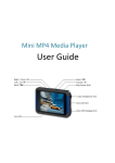
1
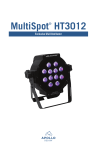
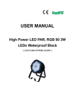
Passive RGB LED panels
Other Quality Products
From Apollo
USER MANUAL
• Stainless Steel Gobos
• Glass Gobos
• PrintScenic™ Plastic and Glass Gobos
•Gel
• Right Arm®
• Smart Color® PRO Scrollers
• Smart Move® Rotators
• Smart Move® Vertical
• Smart Power™ Power Supplies
• EZ Iris DMX
•Tape
•Dichroics
• Pattern Holders
•Cable
• Tuff-Stuff C-Clamps
•Wrenches
MultiSpot HT3012
4130 Fourier Dr., Fort Wayne, IN 46818 USA
Voice: +1.260.497.9191
Fax: +1.260.497.9192
International: (00)+1.260.497.9191
www.apollodesign.net
09-12-13
Table Of Contents
PAGE
PAGE
Introduction....................................................................... 1
Product description............................................................ 1
Security advice before use.................................................. 2
Health advice..................................................................... 3
Functional advice............................................................... 3
Environmental advice........................................................ 3
Unpacking.......................................................................... 3
Getting started: choosing a location.................................. 4
Getting started: secure mounting...................................... 4
Technical data ................................................................... 5
User interface overview:.................................................... 5
Operation........................................................................6-9
Optional accessories......................................................... 10
Warranty.......................................................................... 10
Optional Accessories
Optional accessories include a Mounting Tab Kit and Gel/Diffusion Frames. The Mounting Tab Kit includes three tabs and hardware
required to mount to the front of the HT3012 unit to allow for the use of a Gel/Diffusion Frame. The Gel/Diffusion Frame comes
with a piece of one of three high-transmission materials to change the beam angle from 27° to 32°, 40°, or 65°.
Introduction
Dear Customer,
Congratulations on the purchase of the Multispot HT3012 LED fixture from Apollo. Apollo is the US exclusive distributor for
Multiform, a leading global manufacturer of professional lighting equipment with decades of experience in design, production and
quality assurance.
To meet your requirements this unit has been designed and built to the highest standards, so we can assure that you have made
a sound investment. To take full advantage of all possibilities and for your own safety and the safety of your environment, please
read these operating instructions carefully before you start using the unit.
Product description (check package which applies)
The Multispot HT3012 is an RGB LED panel. The HT3012 LED panel uses 12 ultra-bright 3W RGB LEDs and provides a unique
solution for all indoor applications that require a medium angle, high-brightness color-mixing spot light with maximum ease of
use - from club to stage lighting, from commercial to architectural purposes.
Warranty
Items are covered for defects in materials and workmanship for one year, including repair parts and repair labor on defective item,
from date of Apollo invoice. The warranty covers freight for 30 days after initial purchase. Apollo does not cover any other loss
resulting from product failure.
Products being returned for warranty repair must display the original serial number sticker. Removal of the serial number sticker
voids the product’s limited warranty.
• Despite the care taken for the compilation of this book, Apollo Design Technology, Inc cannot be held responsible for
any damages resulting from errors that may appear in this book. All efforts have been made to provide the most accurate,
up-to-date instructions and illustrations possible.
• Need assistance? Call Apollo at 800-288-4626 for details.
Keep this information handy if requiring technical assistance.
Serial Number
Date Purchased
Purchased From
1
10
“dP” DMX Preset Mode
If you want to run the pre-programmed patterns and scenes by an external DMX-controller you can use the DMX Preset Mode. Press
the MODE button (5) until the display shows “dP”, indicating operation in DMX Preset mode. Set the DMX starting address by using
the UP/DOWN buttons (6/7).
When set to this mode, the unit requires 4 DMX channels.
If DMX-value of channel 3 is lower than 50 the unit works with static colors:
Value Range
Function
CH1
000-255
Output color choice from presets (see “C” mode)
CH2
000-255
Master output level
CH3
000-049
Static color mode active
CH4
000-049
Strobe off
050-255
Strobe (050=slow / 255=max. speed 23 Hz)
Output mix presets can be activated by means of CH1. The chosen mix can be adjusted with CH2. If the value of CH4 is above 50
the unit is set to strobe mode. The strobe speed for any fixed output mix chosen on the first channel can be adjusted from zero
(value <50) to 23 cycles per second (value 255).
If DMX value of channel 3 is equal or higher than 50 the unit works in pattern mode:
CH1
Pattern
CH1
Pattern
000-015
Soft fade Red Green
136-150
Hard fade Green Blue
016-030
Soft fade Green Blue
151-165
Hard fade Red Blue
031-045
Soft fade Red Blue
166-180
Hard fade Red Yellow
046-060
Soft fade Red Yellow
181-195
Hard fade Hot Pink Lime
061-075
Soft fade Hot Pink Lime
196-210
Hard fade Pink Blue
076-090
Soft fade Pink Blue
211-225
Hard fade Turquoise Pink
091-105
Soft fade Turquoise Pink
226-240
Hard fade Red Green Blue
106-120
Soft fade Red Green Blue
241-255
Hard fade All Colors
121-135
Hard fade Red Green
DMX
Value range
Function
CH2
000-255
Level
CH3
050-255
Chase speed
CH4
000-049
Stobe off
050-255
Strobe (050=slow / 255=max. speed 23 Hz)
Addressing has to be done as follows:
001 first device CH 1-4)
005 second device (CH 5-8)
009 third device (CH 9-12)
013 fourth device (CH 13-16) *factory default*
and so on.
9
Warning: Read this section carefully before installing, powering, operating,
cleaning or servicing this product!
The following symbols are used to identify important safety information in this manual:
DMX Channel
In this mode the knob (1) is disabled.
Security advice before use
DANGER!
Safety hazard. Risk
of injury or death.
WARNING!
Hazardous voltage.
Risk of severe or fatal
electric shock.
WARNING!
Fire hazard.
WARNING!
LED light emission.
Risk of severe eye
damage.
WARNING!
Read manual before
installation and
operation.
General advice:
1. Read this manual completely before using the product.
2. Keep this manual in your records for future reference.
3. Follow all instructions printed in this manual, otherwise warranty may become void.
4. Follow all printed security advice on the product. The lightning flash with arrowhead within an equilateral triangle
warns of non-insulated AC main voltage inside the unit. The exclamation mark within an equilateral triangle
warns of important operating and maintenance instructions in the literature attached to this product. Failure to follow all printed instructions in this manual may void the warranty.
5. Carry this product with care. Dropping or heavy vibration may damage this product mechanically and/or electrically.
6. The manufacturer takes no responsibility for injury or damage caused by not following the safety
precautions and instructions printed within this manual.
Warning! Class 1M LED product.
1. Do not look into the beam from a distance of less than 16 inches (40 cm).
2. Do not stare into the beam for extended periods at a short distance.
3. Do not view the beam directly with optical instruments such as magnifiers.
Protection from electric shock:
1. Do not expose this unit to any dripping or splashing liquids. Do not submerge unit. Do not place
objects filled with liquids on the unit. Do not operate this unit near open water
or in high humidity.
2. Do not open the unit for service purposes. There are no user-serviceable parts inside. Warranty will
be void in any case of unauthorized service by the user or other persons.
Protection from fire:
1. Take care not to place the unit near sources of heat (e.g. powerful amplifiers, fog machines).
2. Allow at least 6” between this unit and other devices or a wall to allow for proper cooling.
3. Be sure this fixture is kept at least 24” away from any flammable materials.
4. Allow sufficient air convection in the unit’s environment to avoid overheating. Make sure air
convection slots are not blocked. Do not operate this unit in environmental temperatures
exceeding 105° Fahrenheit.
5. Do not attach gel or diffusion directly to the front of the LEDs unless using accessories on page 9.
2
Protection from injury and damage:
1. Never use accessories or modifications not authorized by the manufacturer of this unit.
2. Choose a location for operation where the unit is protected from vibration and where a fixed
mounting position is provided. In case of overhead mounting, follow appropriate rigging rules
and regulations for rigging safety, including the use of an approved safety cable.
Our units ship with integral power supplies.
3. The connection to a power supply must be carried out by qualified and certified personnel only.
4. Do not expose this unit to any dripping or splashing liquids. Do not operate this unit near or
in open water or in high humidity.
There are no user serviceable parts in the unit. Return the unit to qualified personnel for repair.
“d4” DMX Mode
Press the MODE button (5) until the display shows “d4”, indicating operation in 4 channel DMX mode. Shortly after that, the display
shows the DMX starting address. Set DMX address by using the UP/DOWN buttons (6/7).
In this mode the knob (1) is disabled.
When set to this mode, the unit requires 4 DMX channels.
DMX channel
Value Range
Function
CH1
000-255
Red level
CH2
000-255
Green level
CH3
000-255
Blue level
CH4
000-127
Master output level
128-227
Strobe (128=slow / 227=max. speed 23 Hz)
228-255
Master level full on, Strobe off
Health advice
This unit produces and absorbs electromagnetic radiation. The strength of radiation and the sensitivity for disturbing interference
conforms with CE and FCC requirements. A corresponding sign is printed on the backside of the unit. Any change or modification
may affect the operation of the unit’s electromagnetic radiation. Any modification to the unit will void all electrical certification.
The manufacturer/distributor takes no responsibility in this case.
Functional advice
This unit is immune to the presence of electromagnetic disturbances – both conducted and radiated - up to a certain level. Under
peak conditions, the unit is classified to show a “class C” performance criteria and may encounter temporary degradation or loss of
function. In such a case, power down the connected power supply and power it on again to recover.
“d5” DMX Mode – 5 channels
Press the Mode button (5) until the display shows “d5”, indicating operation in 5 channel DMX mode. Shortly after that, the display
shows the DMX starting address. Set DMX address by using the UP/DOWN buttons (6/7).
In this mode, the knob (1) is disabled.
Environmental advice
When set to this mode, the unit requires 5 DMX channels.
This unit is built to conform to the ROHS standards and the WEEE directive 2002/96/EC of the European Parliament and of the
Council of the European Union. Under these regulations, the product shall not be discarded into regular garbage at the end of its
life, but shall be returned to authorized recycling stations. It is highly recommended that North American users follow environmentally safe disposal/recycling practices.
Unpacking
Please check that the box contains the following items:
Main parts:
Accessory parts:
Addressing has to be done as follows:
001 first device (CH 1-4)
*factory default*
005 second device (CH 5-8)
009 third device (CH 9-12)
013 fourth device (CH 13-16) and so on.
This setting is stored even if the device is switched off.
1 Multispot HT3012
1 operation manual
1 M6 security lug
1 power cable
If any part is missing, please contact your dealer immediately for replacement.
3
DMX channel-
Value Range
Function
CH1
000-255
Red level
CH2
000-255
Green level
CH3
000-255
Blue level
CH4
000-255
Master output level
CH5
000-049
Strobe off
050-255
Strobe (050=slow / 255=max. speed 23 Hz)
Addressing has to be done as follows:
001 first device
(CH 1-5)
*factory default*
006 second device
(CH 6-10)
011 third device
(CH 11-15)
016 fourth device
(CH 16-20)
and so on.
This setting is stored even if the device is switched off.
8
Getting started: choosing a location
“C” Color Mode
Press the MODE button (5) until the first digit on the display shows “C”, indicating operation in “color” mode. Choose a color by
using the UP/DOWN buttons (6/7), see list below.
Risk of fire:
These units of passive RGB LED panels have been designed to work in dry indoor
environments at environmental temperatures up to 105 degrees Fahrenheit.
Do not:
• Operate the units of passive RGB LED panels in environments with more than 105°F
environmental temperature or more than 80% humidity.
• Operate the units of passive RGB LED panels in any closed environment,
unless forced air convection is provided.
• Operate less than 24” distance from any flammable surface.
NOTE: The “C” Mode is automatically disabled when an external DMX signal is present.
Knob (1) determines the output level.
Available color presets:
C0
all off
C10
Blue Green
C1
Red
C11
Lavender
C2
Green
C12
Hot Pink
C3
Blue
C13
Flesh
C4
Yellow
C14
Light Blue Green
C5
Pink
C15
Light Green
C6
Turquoise
C16
Light Purple
C7
Lime
C17
Light Lavender
C8
Orange
C18
Light Blue
C9
Marine
C19
White
DMX Modes
NOTE: To use unit in slave mode, select the “d3” DMX Mode. The unit will receive DMX data from another unit
which is in “A” or “C” mode and must be set to channel 1.
The unit receives DMX data and mirrors the received data on the DMX output (13). If a DMX signal is present, the DMX LED (3) will
turn on. Refer to the DMX modes below for channel information.
“d3” DMX Mode – 3 channels
Press the Mode button (5) until the display shows “d3”, indicating operation in 3 channel DMX mode or slave mode. Shortly after
that, the display shows the DMX starting address. Set DMX address by using the UP/DOWN buttons (6/7).
In this mode, the knob (1) is disabled.
When set to this mode, the unit requires 3 DMX channels.
DMX channel
Value Range
Function
CH1
000-255
Red level
CH2
000-255
Green level
CH3
000-255
Blue level
Addressing has to be done as follows:
001 first device
(CH 1-3)
*factory default*
004 second device
(CH 4-6)
007 third device
(CH 7-9)
010 fourth device
(CH 10-12)
and so on.
This setting is stored even if the device is switched off.
7
Getting started: secure mounting
The units of passive RGB LED panels can be mounted in various ways:
Floor standing operation
• Turn the bracket to the lower side of the unit and fold out the second bracket.
• Place the unit in a secure position.
• Use the provided cable slots in the bracket to route cables.
• Make sure to comply with cooling requirements of the power supply.
Hanging/Rigging, ceiling-mounted operation
Risk of injury:
Overhead mounting requires extensive experience, including among others calculating working load limits,
good knowledge of the installation material being used, and periodic safety inspection of all installation
material and the unit. If you lack such qualifications, do not attempt the installation yourself. Improper
installation can result in body injury. Be sure to complete all rigging and installation procedures before
applying power to the unit.
• Leave the inner and outer bracket folded.
• The unit should be installed out of reach of people and areas where persons may walk or be seated.
• Make sure that the installation area can hold a minimum point load of 10 times the device’s weight.
• In fixed installations, attach the unit with self-locking screws/nuts to the mounting point.
• When mounting the unit to truss be sure to secure an appropriately rated clamp, available from Apollo,
to the hanging yoke through the center hole of the hanging yoke.
• Attach the supplied M6 safety lug to the rear side thread insert rigging point and secure the installation
with an appropriate safety cable fixed to an individual separate mounting point. Be sure to only
use the designated rigging point for the safety cable.
• Always use a certified safety cable that can hold 12 times the weight of the device when installing the
unit. This secondary safety attachment should be installed in a way that no part of the installation can
drop more than 9” if the main attachment fails.
• Never stand directly below the device when mounting, removing, or servicing the fixture.
• The installations should be inspected every year by a skilled person to ensure safety.
• Use the provided cable securing slots in the bracket to secure any cables using a cable tie.
• Make sure to comply with cooling requirements of the power supply.
4
Technical data:
Operation
Multispot HT3012
LED’s, total
12 RGB
LED’s red
12
LED’s green
12
LED’s blue
12
LED type
3W RGB
Beam angle
25°
Power requirements 45W
Max Current sensing
Weight
6.3 lbs (2.9 kg)
Multispot HT3012
User interface
overview:
8
1
2
4
3
5
6
9
10
11
7
1. In A-Mode:
Speed Control (except A1= Mix Control)
In C-Mode: Level-Control
2. Display showing the Mode,
DMX-address, LOC-function etc.
3. Indicates presence of a DMX signal
4. Indicates the sound-activated mode (internal microphone)
5. MODE selection button
6.UP-button
7.DOWN-button
8. Internal microphone
12
13
14
9. Switches on or off the termination
for the last unit in the DMX-chain
10. Switching the display on or off
(with delay)
11. Maintenance (not in use)
12. VOLTAGE-Input 90-250VAC 50/60 Hz
Auto Sensing
13. DMX-Output connector
14. DMX-Input connector
5
The HT3012 has several operating modes for internal and external operation.
“A” Auto Mode
Press the MODE button (5) until the first digit on the display shows “A”, indicating operation in “auto” mode. Choose a pattern by
using the UP/DOWN buttons (6/7), see list below.
NOTE: The “A” Mode is automatically disabled when an external DMX signal is present.
Use control knob (1) to mix color in pattern 1.
Use control knob (1) to select speed in pattern 2 through 27.
Use control knob (1) from 0 to 10% to activate sound control feature for pattern 10 through 18 and 23 through 27.
Use control knob (1) from 11 to 100% to control speed for pattern 10 through 18 and 23 through 27.
#
A0
A1
A2
A3
A4
A5
A6
A7
A8
A9
A10
A11
A12
A13
A14
A15
A16
A17
A18
A19
A20
A21
A22
A23
A24
A25
A26
A27
Description
All off
Static scene
Soft fade Red Green Mix
Soft fade Green Blue Mix
Soft fade Red Blue Mix
Soft fade Red Green Mix 2
Soft fade Green Blue Mix 2
Soft fade Red Blue Mix 2
Soft fade Blue Magenta Mix
Soft fade Red Green Blue
Hard fade Red Green
Hard fade Green Blue
Hard fade Red Blue
Hard fade Red Amber
Hard fade Green Magenta
Hard fade Blue Magenta
Hard fade Light Blue Magenta
Hard fade Red Green Blue
Hard fade all colors
Random speed Red Yellow
Random speed Blues
Random speed Red Blue Magenta
Random speed All
Strobe White
Strobe Red
Strobe Green
Strobe Blue
Strobe Red Green Blue
Function of Knob (1)
None
Mix
Speed
Speed
Speed
Speed
Speed
Speed
Speed
Speed
Sound-activation, Speed
Sound-activation, Speed
Sound-activation, Speed
Sound-activation, Speed
Sound-activation, Speed
Sound-activation, Speed
Sound-activation, Speed
Sound-activation, Speed
Sound-activation, Speed
None
None
None
None
Sound-activation, Speed
Sound-activation, Speed
Sound-activation, Speed
Sound-activation, Speed
Sound-activation, Speed
6