1
7-8
Step 7 - Wire the Control Signal Terminal Block
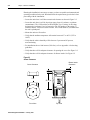
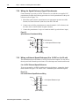
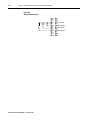
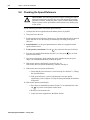
7.5.2 Wiring the Speed Reference Signal Potentiometer
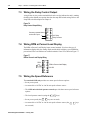
Control terminal 1 provides a 10 VDC reference for use with the user-supplied 5 kΩ
potentiometer. Perform the following procedure to wire the potentiometer as the speed
reference (refer to Figure 7.9):
1. Mount the speed reference potentiometer at an appropriate operator-accessible
location, less than 300 meters (1000 feet) from the 1329I unit.
2. Connect one end of the potentiometer to control terminal 1 (10V reference) and
the other end to control terminal 4 (signal common).
3. Connect the potentiometer’s wiper to control terminal 2 (speed reference input).
Figure 7.9
Speed Reference Potentiometer Wiring
Shield
5K Ω
1 2 3 4 5
+10V DC
10 Volt Reference
0 – 10 Volt Speed Reference Input
Common
(Drive end only)
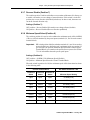
7.5.3 Wiring an External Speed Reference (0 to 10 VDC or 4 to 20 mA)
The terminal block provides both 0 to 10 VDC and 4 to 20 mA inputs. Use only one of
these inputs for the external speed reference. The other input must remain unconnected.
0 to 10 VDC External Speed Reference
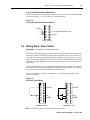
To use an external 0 to 10 VDC signal to set the speed reference, connect the signal
leads as shown in Figure 7.10. 0 to 10 VDC = minimum speed to maximum speed
Figure 7.10
0 to 10 VDC External Speed Reference Wiring
+
–
1 2 3 4 5
Shield
0 – 10 Volt Speed Reference Input
Common
(Drive end only)
1329I-5.0 Integrated Drive/Motor — January, 1999