1
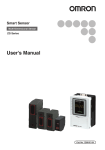
Smart Sensor
Data Storage Unit
ZG2-DSU
User’s Manual
Cat.No
Z289-E1-02
Introduction
Thank you for purchasing the ZG2 Data Storage Unit (ZG2-DSU).
This manual provides information regarding functions, performance and operating methods that
are required for using the ZG2-DSU.
When using the ZG2-DSU, be sure to observe the following:
• The ZG2-DSU must be operated by personnel knowledgeable in electrical engineering.
• To ensure correct use, please read this manual thoroughly to deepen your understanding of the
product.
• Please keep this manual in a safe place so that it can be referred to whenever necessary.
About Trademarks
• Microsoft and Windows are either registered trademarks or trademarks of Microsoft Corp. in the
United States and/or other countries.
• CompactFlash is a trademark of SanDisk Corporation.
• Other product and company names herein may be either registered trademarks or trademarks of
their respective owners.
How to Switch the Display Language to English
Turn the power ON with the MENU key held down.
This displays the display language selection screen.
Select Language
1 Japanese 2 English
The unit will start up with the messages displayed in English when it is next started up.
READ AND UNDERSTAND THIS
DOCUMENT (Please Read)
BEFORE USE
1
User's Manual
LOGGING FUNCTIONS
2
EXTERNAL BANK FUNCTIONS
SETTING
TIONS
ADDITIONAL
FUNC-
COMMUNICATION WITH EXTERNAL DEVICES
APPENDICES
Smart Sensor
Data Storage Unit
ZG2-DSU
3
4
5
6
READ AND UNDERSTAND THIS DOCUMENT
Please read and understand this document before using the products. Please consult
your OMRON representative if you have any questions or comments.
WARRANTY
OMRON’s exclusive warranty is that the products are free from defects in materials and
workmanship for a period of one year (or other period if specified) from date of sale by
OMRON.
OMRON MAKES NO WARRANTY OR REPRESENTATION, EXPRESS OR IMPLIED,
REGARDING NON-INFRINGEMENT, MERCHANTABILITY, OR FITNESS FOR
PARTICULAR PURPOSE OF THE PRODUCTS. ANY BUYER OR USER
ACKNOWLEDGES THAT THE BUYER OR USER ALONE HAS DETERMINED THAT
THE PRODUCTS WILL SUITABLY MEET THE REQUIREMENTS OF THEIR INTENDED
USE. OMRON DISCLAIMS ALL OTHER WARRANTIES, EXPRESS OR IMPLIED.
LIMITATIONS OF LIABILITY
OMRON SHALL NOT BE RESPONSIBLE FOR SPECIAL, INDIRECT, OR
CONSEQUENTIAL DAMAGES, LOSS OF PROFITS OR COMMERCIAL LOSS IN ANY
WAY CONNECTED WITH THE PRODUCTS, WHETHER SUCH CLAIM IS BASED ON
CONTRACT, WARRANTY, NEGLIGENCE, OR STRICT LIABILITY.
In no event shall responsibility of OMRON for any act exceed the individual price of the
product on which liability is asserted.
IN NO EVENT SHALL OMRON BE RESPONSIBLE FOR WARRANTY, REPAIR, OR
OTHER CLAIMS REGARDING THE PRODUCTS UNLESS OMRON’S ANALYSIS
CONFIRMS THAT THE PRODUCTS WERE PROPERLY HANDLED, STORED,
INSTALLED, AND MAINTAINED AND NOT SUBJECT TO CONTAMINATION, ABUSE,
MISUSE, OR INAPPROPRIATE MODIFICATION OR REPAIR.
SUITABILITY FOR USE
THE PRODUCTS CONTAINED IN THIS DOCUMENT ARE NOT SAFETY RATED. THEY
ARE NOT DESIGNED OR RATED FOR ENSURING SAFETY OF PERSONS, AND
SHOULD NOT BE RELIED UPON AS A SAFETY COMPONENT OR PROTECTIVE
DEVICE FOR SUCH PURPOSES.
Please refer to separate catalogs for OMRON’s safety rated products.
OMRON shall not be responsible for conformity with any standards, codes, or regulations
that apply to the combination of products in the customer’s application or use of the
product.
At the customer’s request, OMRON will provide applicable third party certification
documents identifying ratings and limitations of use that apply to the products. This
information by itself is not sufficient for a complete determination of the suitability of the
products in combination with the end product, machine, system, or other application or use.
The following are some examples of applications for which particular attention must be
given. This is not intended to be an exhaustive list of all possible uses of the products, nor
is it intended to imply that the uses listed may be suitable for the products:
• Outdoor use, uses involving potential chemical contamination or electrical interference,
or conditions or uses not described in this document.
2
ZG2-DSU User’s Manual
• Nuclear energy control systems, combustion systems, railroad systems, aviation
systems, medical equipment, amusement machines, vehicles, safety equipment, and
installations subject to separate industry or government regulations.
• Systems, machines, and equipment that could present a risk to life or property.
Please know and observe all prohibitions of use applicable to the products.
NEVER USE THE PRODUCTS FOR AN APPLICATION INVOLVING SERIOUS RISK TO
LIFE OR PROPERTY WITHOUT ENSURING THAT THE SYSTEM AS A WHOLE HAS
BEEN DESIGNED TO ADDRESS THE RISKS, AND THAT THE OMRON PRODUCT IS
PROPERLY RATED AND INSTALLED FOR THE INTENDED USE WITHIN THE
OVERALL EQUIPMENT OR SYSTEM.
PERFORMANCE DATA
Performance data given in this document is provided as a guide for the user in determining
suitability and does not constitute a warranty. It may represent the result of OMRON’s test
conditions, and the users must correlate it to actual application requirements. Actual
performance is subject to the OMRON Warranty and Limitations of Liability.
CHANGE IN SPECIFICATIONS
Product specifications and accessories may be changed at any time based on
improvements and other reasons.
It is our practice to change model numbers when published ratings or features are
changed, or when significant construction changes are made. However, some
specifications of the product may be changed without any notice. When in doubt, special
model numbers may be assigned to fix or establish key specifications for your application
on your request. Please consult with your OMRON representative at any time to confirm
actual specifications of purchased products.
DIMENSIONS AND WEIGHTS
Dimensions and weights are nominal and are not to be used for manufacturing purposes,
even when tolerances are shown.
ERRORS AND OMISSIONS
The information in this document has been carefully checked and is believed to be
accurate; however, no responsibility is assumed for clerical, typographical, or
proofreading errors, or omissions.
PROGRAMMABLE PRODUCTS
OMRON shall not be responsible for the user’s programming of a programmable product,
or any consequence thereof.
COPYRIGHT AND COPY PERMISSION
This document shall not be copied for sales or promotions without permission.
This document is protected by copyright and is intended solely for use in conjunction with
the product. Please notify us before copying or reproducing this document in any manner,
for any other purpose. If copying or transmitting this document to another, please copy or
transmit it in its entirety.
ZG2-DSU User’s Manual
3
Meanings of Signal Words
The following signal words are used in this manual.
Indicates a potentially hazardous situation which, if not
avoided, will result in minor or moderate injury, or may result in
serious injury or death. Additionally there may be significant
property damage.
Meanings of Alert Symbols
The following alert symbols are used in this manual.
Indicates the possibility of explosion under specific conditions.
This product has a built-in lithium battery. This battery might, in rare
cases, ignite or rupture, and cause major injury.
Do not disassemble, pressurize, or incinerate this product at a
temperature of 100°C or more.
4
ZG2-DSU User’s Manual
Precautions for Safe Use
The following points are important to ensure safety, so make sure that they are strictly
observed.
1. Installation Environment
• Do not use the product in environments where it can be exposed to inflammable/
explosive gas.
• To secure the safety of operation and maintenance, do not install the product close to
high-voltage devices and power devices.
2. Power Supply and Wiring
•
•
•
•
•
The voltage and AC power supply must be within the rated range (DC 24 V ±10%).
Reverse connection of the power supply is not allowed.
Open-collector outputs should not be short-circuited.
Use the power supply within the rated load.
High-voltage lines and power lines must be wired separately from this product. Wiring
them together or placing in the same duct may cause induction, resulting in
malfunction or damage.
3. Regulations and Standards
• EN61326-1
• Electromagnetic environment : Industrial electromagnetic environment (EN/IEC 61326-1
Table 2)
• Notice for Korea Radio Law
A급 기기 (업무용 방송통신기자재)
이 기기는 업무용 ( A급 ) 전자파적합기기로서 판매자
또는 사용자는 이 점을 주의하시기 바라며 , 가정외의
지역에서 사용하는 것을 목적으로 합니다.
4. Other
• Do not disassemble, repair, or modify the product.
• Dispose of this product as industrial waste.
ZG2-DSU User’s Manual
5
Precautions for Correct Use
Observe the following precautions to prevent failure to operate, malfunctions, or
undesirable effects on product performance.
1. Installation Site
Do not install this product in locations subjected to the following conditions:
• Ambient temperature outside the rating
• Rapid temperature fluctuations (causing condensation)
• Relative humidity outside the range of 35 to 85%
• Presence of corrosive or flammable gases
• Presence of dust, salt, or iron particles
• Direct vibration or shock
• Reflection of intense light (such as other laser beams or electric arc-welding
machines)
• Direct sunlight or near heaters
• Water, oil, or chemical fumes or spray
• Strong magnetic or electric field
2. Power Supply and Wiring
• When using a commercially available switching regulator, make sure that the FG
terminal is grounded.
• If surge currents are present in the power lines, connect surge absorbers that suit the
operating environment.
• Before turning ON the power after the product is connected, make sure that the power
supply voltage is correct, there are no incorrect connections (e.g. load short-circuit),
and the load current is appropriate. Incorrect wiring may result in breakdown of the
product.
• Before connecting/disconnecting devices, make sure that the devices are turned OFF.
The devices may break down if it is connected/disconnected while the power is ON.
• Use only combinations of the Sensor Controller specified in this manual.
3.Maintenance and Inspection
Do not use thinner, benzene, acetone or kerosene to clean the Data Storage Unit.
4.Compatibility of Mesurement Data
This product is the dedicated data storage unit for ZG2 series.
Data cannot be logged when existing ZG series products are connected to the Data
Storage Unit.
Bank data or System data saved using ZG series cannot be processed with this product.
6
ZG2-DSU User’s Manual
Editor’s Note
■ Meaning of Symbols
Menu items that are displayed on the Data Storage Unit’s LCD screen, and windows, dialog
boxes and other GUI elements displayed on the PC are indicated enclosed by brackets “[ ]”.
■ Visual Aids
Important
Note
Indicates points that are important to achieve the full product performance,
such as operational precautions or tips.
Provide helpful information in use.
Indicates pages where related information can be found.
ZG2-DSU User’s Manual
7
MEMO
8
ZG2-DSU User’s Manual
CONTENTS
1.BEFORE USE
Data Storage Unit . . . . . . . . . . . . . . . . . . . . . . . . . . . . . 14
System Configuration . . . . . . . . . . . . . . . . . . . . . . . . . . 14
Part Names and Functions . . . . . . . . . . . . . . . . . . . . . . 15
Mounting and Connecting Devices . . . . . . . . . . . . . . 17
Gang-mounting to a Controller . . . . . . . . . . . . . . . . . . . 18
Attaching the Ferrite Core . . . . . . . . . . . . . . . . . . . . . . 19
1
Connecting the Power Supply . . . . . . . . . . . . . . . . . . . 19
CONTENTS
Inserting and Removing Memory Cards . . . . . . . . . . . . 20
Functions of the Data Storage Unit . . . . . . . . . . . . . . 22
Logging Function . . . . . . . . . . . . . . . . . . . . . . . . . . . . . 22
External Bank Function . . . . . . . . . . . . . . . . . . . . . . . . 22
Initializing Controller Settings . . . . . . . . . . . . . . . . . . 23
Saving Setup Data . . . . . . . . . . . . . . . . . . . . . . . . . . . . 24
2.LOGGING FUNCTIONS
Logging Procedure . . . . . . . . . . . . . . . . . . . . . . . . . . . 26
How Logging Works . . . . . . . . . . . . . . . . . . . . . . . . . . 27
Possible Number of Logging Data . . . . . . . . . . . . . . . . 28
Format of Data Saved to Memory Card . . . . . . . . . . . . 29
Select the Logging Target . . . . . . . . . . . . . . . . . . . . . . 31
Logging Measurement Values . . . . . . . . . . . . . . . . . . . 31
Logging Profiles . . . . . . . . . . . . . . . . . . . . . . . . . . . . . . 31
Setting Logging Conditions . . . . . . . . . . . . . . . . . . . . 32
Logging Only at an NG/Only at an OK . . . . . . . . . . . . . 32
Logging by All Conditions . . . . . . . . . . . . . . . . . . . . . . . 32
Logging at a Fixed Cycle . . . . . . . . . . . . . . . . . . . . . . . 33
ZG2-DSU User’s Manual
9
Logging at Individual Fixed Counts . . . . . . . . . . . . . . . 33
Specify the Logging Cycle by an External Signal . . . . . 33
Starting and Ending Logging . . . . . . . . . . . . . . . . . . . 34
Starting Logging . . . . . . . . . . . . . . . . . . . . . . . . . . . . . . 34
Ending Logging . . . . . . . . . . . . . . . . . . . . . . . . . . . . . . . 34
Loading Logging Data to an External Device . . . . . . 35
Removing the Memory Card and Copying Logging Data 35
Copying Logging Data by Serial Communication Commands . . . . . . . . . . . . . . . . . . . . . . . . . . . . . . . . . . . . . . 35
3.EXTERNAL BANK FUNCTIONS
Saving Bank Data to Memory Cards . . . . . . . . . . . . . 38
Transferring Bank Data to the Controller . . . . . . . . . 39
4.SETTING ADDITIONAL FUNCTIONS
Judging Measurement Values (Alarm Outputs) . . . . 42
Specifying Tasks . . . . . . . . . . . . . . . . . . . . . . . . . . . . . 42
Setting Judgment Conditions . . . . . . . . . . . . . . . . . . . . 42
Setting System Conditions . . . . . . . . . . . . . . . . . . . . . 44
Setting the System Clock . . . . . . . . . . . . . . . . . . . . . . . 44
Locking Keys . . . . . . . . . . . . . . . . . . . . . . . . . . . . . . . . 44
Memory Card Operations . . . . . . . . . . . . . . . . . . . . . . . 44
Changing the Display Language . . . . . . . . . . . . . . . . . 45
Displaying Data Storage Unit Information . . . . . . . . . . 45
Display Settings during Operation . . . . . . . . . . . . . . . 46
Setting the Digital Display . . . . . . . . . . . . . . . . . . . . . . . 46
LCD Screen Settings . . . . . . . . . . . . . . . . . . . . . . . . . . 47
Bank Functions . . . . . . . . . . . . . . . . . . . . . . . . . . . . . . 49
Switching Banks . . . . . . . . . . . . . . . . . . . . . . . . . . . . . . 49
Clearing Banks . . . . . . . . . . . . . . . . . . . . . . . . . . . . . . . 49
10
ZG2-DSU User’s Manual
5.COMMUNICATION WITH EXTERNAL
DEVICES
List of Output Data . . . . . . . . . . . . . . . . . . . . . . . . . . . 52
Communication Using I/O Signals . . . . . . . . . . . . . . . 53
Using the Controller I/O Cable . . . . . . . . . . . . . . . . . . . 53
Timing Charts . . . . . . . . . . . . . . . . . . . . . . . . . . . . . . . . 56
Logging . . . . . . . . . . . . . . . . . . . . . . . . . . . . . . . . . . . . . 56
Transferring Bank Data . . . . . . . . . . . . . . . . . . . . . . . . 57
Alarm Output . . . . . . . . . . . . . . . . . . . . . . . . . . . . . . . . 57
Serial Communication . . . . . . . . . . . . . . . . . . . . . . . . . 58
RS-232C Specifications . . . . . . . . . . . . . . . . . . . . . . . . 58
Communication Commands . . . . . . . . . . . . . . . . . . . . . 59
Measurement Value Acquisition/Profile Acquisition Commands . . . . . . . . . . . . . . . . . . . . . . . . . . . . . . . . . . . . . . 61
Bank Data Transfer Commands . . . . . . . . . . . . . . . . . . 65
Setting Acquisition/Change Commands . . . . . . . . . . . . 66
Bank Control Commands . . . . . . . . . . . . . . . . . . . . . . . 69
Parameter List . . . . . . . . . . . . . . . . . . . . . . . . . . . . . . . 71
6.APPENDICES
CONTENTS
Utility Commands . . . . . . . . . . . . . . . . . . . . . . . . . . . . . 70
Specifications and External Dimensions . . . . . . . . . 74
Data Storage Unit . . . . . . . . . . . . . . . . . . . . . . . . . . . . . 74
Error Messages and Corrective Actions . . . . . . . . . . 77
Menu List . . . . . . . . . . . . . . . . . . . . . . . . . . . . . . . . . . . 79
Basic Knowledge for Operation . . . . . . . . . . . . . . . . . 81
How to Select Menus . . . . . . . . . . . . . . . . . . . . . . . . . . 81
Updating the Firmware . . . . . . . . . . . . . . . . . . . . . . . . 83
INDEX . . . . . . . . . . . . . . . . . . . . . . . . . . . . . . . . . . . . . . 85
Revision History . . . . . . . . . . . . . . . . . . . . . . . . . . . . . 88
ZG2-DSU User’s Manual
11
MEMO
12
ZG2-DSU User’s Manual
1
BEFORE USE
BEFORE USE
Data Storage Unit
14
Mounting and Connecting Devices
17
Functions of the Data Storage Unit
22
Initializing Controller Settings
23
Saving Setup Data
24
Data Storage Unit
The Data Storage Unit collects and acquires measurement values and profiles from the
Sensor Controller installed on site, and can save this data to Memory Card. Data saved
on Memory Card can be easily loaded to a PC for use in data analysis and operations.
Measurement conditions for up to 4096 banks (16 banks x 256 files) can be registered to
an inserted Memory Card as an external bank for the Sensor Controller. Also, thresholds
can be set for data currently being logged and used as alarm output functions.
System Configuration
Sensor Head
Memory Card
Controller Link Unit
ZS-XCN
F160-N128S
F160-N265S
Required when the Data
Storage Unit is connected
to the Sensor Controller.
USB
PC
Data Storage Unit
Sensor Controller
ZG2-DSU11/DSU41
ZG2-WDC11/WDC41
Up to two Sensor
Controllers can be
gang-mounted.
Data on the Data Storage Unit can
be easily captured to a PC by serial
communication, a USB connection
or by directly reading the Memory
Card.
RS-232C connector cable (option)
Exclusive cables are available to match the
connected device.
For PC
: ZS-XRS2
For PLC/PT : ZS-XPT2
PLC
14
Data Storage Unit
ZG2-DSU User’s Manual
Part Names and Functions
(1)
(2)
(3)
1
(4)
BEFORE USE
(5)
(10)
(6)
(7)
(9)
(8)
(11)
(12)
(14)
(13)
Name
Function
(1) CF power LED
Displays the status of the power supplied to the Memory Card. This
LED turns ON when power is ON, and turns OFF when power is
OFF.
(2) CF access LED
This LED turns ON when the Memory Card is being accessed.
(3) Error LED
This LED turns ON when a Memory Card read/write error occurs.
(4) Memory Card slot
This slot is for inserting the Memory Card.
(5) Digital display
This displays measurement values currently being logged,
remaining amount of space on the Memory Card, and other
information.
(6) LCD screen
ZG2-DSU User’s Manual
FUN mode
This mode displays the menu for setting
logging conditions.
TEACH mode
This mode displays the menu for setting
alarm output thresholds.
RUN mode
This mode displays the menu for setting
up the content of the digital display and
other display-related settings. Settings for
using the Memory Card as an external
bank are also made in this mode.
Data Storage Unit
15
Name
Function
(7) Control keys
These keys are for setting logging conditions and other information.
Control key functions change according to the selected operation
mode.
List of Key Operations p.82
(8) Mode switch
This switch selects the operation mode.
FUN:
This mode displays the menu for setting logging
conditions.
TEACH: This mode displays the menu for setting alarm output
thresholds.
RUN:
Normally select this mode when performing logging.
(9) Threshold selection
switch
Select which of the HIGH or LOW thresholds is to be set (or
displayed).
(10) OUT LED
This LED turns ON during alarm output.
(11) Gang mount
Use this connector for connecting the Data Storage Unit to the
Controller Link Unit.
(12) RS-232C
connector
Connect the RS-232C cable (exclusive product) when you are
connecting the Data Storage Unit to a personal computer which
does not have a USB port.
RS-232C cable p.14
16
(13) I/O cable
Connect this cable to the power supply.
(14) USB port
Connect the USB cable (MINI-B) to the USB port to connect to a
personal computer.
Data Storage Unit
ZG2-DSU User’s Manual
Mounting and Connecting Devices
This section describes installation of the Data Storage Unit.
BEFORE USE
To improve heat radiation, install the Data Storage Unit only in the
orientation shown below.
1
Cautions Regarding the Mounting Orientation
Do not install the Data Storage Unit in the following orientations:
Important
•Do not block the ventilation holes at the top and bottom of the Data Storage Unit body. Doing
so will cause heat to build up inside and result in a malfunction.
•When the temperature inside the control panel exceeds the ambient temperature of 50°C,
provide forced-air cooling or more space at surrounding areas, or improve air circulation to
lower the ambient temperature to 50°C or less.
ZG2-DSU User’s Manual
Mounting and Connecting Devices
17
Gang-mounting to a Controller
For details on how to gang-mount and install devices, refer to the ZG2 series
User's Manual.
CH number when Controllers are gang-mounted
In the gang-mounted arrangement, the Data Storage Unit must be located at the leftmost
end viewed from the front.
When the unit is gang-mounted, the CH number is assigned automatically.
ZG2-DSU
ZG2-WDC
OUTPUT
RUN
CH0
ZG2-DSU
CH0
18
CH1
ZG2-WDC
ZG2-WDC
OUTPUT
OUTPUT
RUN
RUN
CH1
CH2
Mounting and Connecting Devices
ZG2-DSU User’s Manual
Attaching the Ferrite Core
1
1
Attach the ferrite core (supplied)
to the Data Storage Unit's I/O
cable.
BEFORE USE
Ferrite core
Connecting the Power Supply
H
P
L
LD
ON
1
ZE
RO
EN
Connect the power wire (brown)
and GND wire (blue) of the Sensor
Controller's I/O cable to the 24
VDC (±10%) power supply.
AB
LE
Note
The following power supply is recommended:
• S8VS-03024 (24 VDC, 1.3 A)
Be sure to connect the Data Storage Unit to
the power supply in a 1:1 connection.
ZG2-DSU User’s Manual
Mounting and Connecting Devices
19
Inserting and Removing Memory Cards
Important
The following Memory Cards can be used on this unit.
•F160-N128S (128 MB)
•F160-N256S (256 MB)
Inserting Memory Cards
1
2
Protective
dummy card
EJECT button
3
Press the EJECT button at the
side of the Memory Card slot.
Remove the protective dummy
card from the unit.
Insert the Memory Card.
Com
pact
Flas
h
ME
MO
RY
OM
CA
RD
IN A
RON
Memory Card
Removing Memory Cards
Important
Before removing a Memory Card from the unit, make sure that the CF power LED and access
LED are both OFF. If a Memory Card is removed with these LEDs still ON, there is the
possibility that data stored on the Memory Card might be lost or the Memory Card or Data
Storage Unit might malfunction.
FUN
1
Switch to the FUN mode.
2
Select [SYSTEM].
3
Select [EJECT].
RUN
TEACH
20
1 SOURCE
3 BANK
2 I/O SET
4 SYSTEM
1 EJECT
3 INIT
2 SAVE
←→
Mounting and Connecting Devices
ZG2-DSU User’s Manual
Eject CF?
1 OK
4
2 CANCEL
6
Remove the Memory Card.
Com
pact
Flas
h
D
AR
RY
C
MO
ME
OM
RON
IN A
EJECT button
Important
When Memory Cards are not to be used on the
unit for a long time, insert the protective dummy
card.
ZG2-DSU User’s Manual
Mounting and Connecting Devices
BEFORE USE
Memory Card
Press the EJECT button at the
side of the Memory Card slot.
1
5
Select [OK].
The CF power LED turns OFF.
21
Functions of the Data Storage Unit
Logging Function
Measurement values and profile data can be saved on the Data Storage Unit.Saved data
can be loaded to a PC from a Memory Card or via USB/serial communication for use in
managing production logs, monitoring trends and analyzing trouble that may occur.
Memory Card
Host PC
USB/RS-232C
Logging is performed according to the following five conditions:
•
•
•
•
•
Only at an NG/only at an OK p.32
All conditions p.32
At a fixed cycle p.33
At individual fixed counts p.33
At a logging cycle specified by an external signal p.33
External Bank Function
The Data Storage Unit can be used as an external bank for the Sensor Controller.
Measurement conditions for up to 4096 banks can be registered to an inserted Memory
Card, which enables a speedy response on multi-product production lines.
Measurement
conditions for up to
4096 different
products can be
saved on a Memory
Card inserted on the
Data Storage Unit.
Measurement
conditions for up to
16 different
products can be
saved on a Sensor
Saving bank data to Memory Cards p.38
Transferring bank data to the Controller p.39
22
Functions of the Data Storage Unit
ZG2-DSU User’s Manual
Initializing Controller Settings
Important
FUN
1
Switch to the FUN mode.
2
Select [SYSTEM].
BEFORE USE
Acquiring setup data <DATAGET command> p.66
1
The settings of all banks and logging data are initialized regardless of the currently saved bank
No. and logging data. To save settings and data, back them up to a personal computer before
performing initialization.
RUN
TEACH
1 SOURCE
3 BANK
2 I/O SET
4 SYSTEM
1 EJECT
3 INIT
2 SAVE
4 INFO
Initialize?
1 OK
Is it all right?
1 OK
4
2 CANCEL
5
Select [INIT].
The confirmation
displayed.
message
is
Select [OK].
The final confirmation message is
displayed.
Select [OK].
2 CANCEL
INITIALIZE Executed
ZG2-DSU User’s Manual
3
The settings are initialized, and the
"INITIALIZE Executed" message is
displayed.
Initializing Controller Settings
23
Saving Setup Data
Bank settings and system settings made on the Data Storage Unit can be saved internally
on the Data Storage Unit.
Important
•The settings of all banks are saved regardless of the currently selected bank No.
•After you have made settings, be sure to save the setup data. All settings will be deleted if you
turn the power OFF without saving the data. A message prompting you to save data will be
displayed if you change the operation mode without saving data after you have changed
settings.
FUN
1
Switch to the FUN mode.
2
Select [SYSTEM].
3
Select [SAVE].
RUN
TEACH
1 SOURCE
3 BANK
2 I/O SET
4 SYSTEM
1 EJECT
3 INIT
2 SAVE
←→
Save the data?
1 OK
2 CANCEL
Is it all right?
1 OK
5
Saving Setup Data
Select [OK].
The final confirmation message is
displayed.
Select [OK].
2 CANCEL
SYSTEMDATA SAVE
Executed
24
4
The settings are saved, and the
"SYSTEMDATA SAVE Executed"
message is displayed.
ZG2-DSU User’s Manual
LOGGING FUNCTIONS
2
LOGGING FUNCTIONS
Logging Procedure
26
How Logging Works
27
Select the Logging Target
31
Setting Logging Conditions
32
Starting and Ending Logging
34
Loading Logging Data to an External Device35
Logging Procedure
Step 1
Select the logging target.
Measurement value p.31
Profile p.31
Step 2
Only at an NG/only at an OK p.32
Set conditions to be used for
logging.
Log by all conditions p.32
Log at a fixed cycle p.33
Log at individual fixed counts p.33
Specify the logging cycle by an
external signal p.33
Step 3
Starting logging p.34
Start logging.
Step 4
Ending logging p.34
End logging.
Step 5
Load logging data to the PC.
Removing the Memory Card and
copying logging data to a PC p.35
Loading logging data to a PC by
serial communication commands
p.35
26
Logging Procedure
ZG2-DSU User’s Manual
How Logging Works
The Data Storage Unit logs measurement values and profiles by the following
mechanism.
Data Storage Unit
Sensor Controller
(2) Logging execution
(1) Logging start
START signal/↑ key
2
Internal
memory
(4) Copy to Memory Card
Memory
Card
Process
Description
(1) Logging start
Logging is started by the START signal or by the ↑ key.
(2) Logging execution
Measurement results and profiles are logged to the ZG2-DSU's
internal memory in accordance with preset logging conditions.
(3) Logging end
Logging is ended by the STOP signal or by the ↓ key.
LOGGING FUNCTIONS
(measurement result/profile)
(3) Logging end
STOP key/↓ key
(4) Copy to Memory Card Logging data is copied automatically after logging ends to the
Memory Card from the ZG2-DSU's internal memory.
Note
Approximate time required for copying logging data to Memory Card
Timing charts p.56
ZG2-DSU User’s Manual
How Logging Works
27
Possible Number of Logging Data
Possible Number of Logs to Internal Memory
Logged Data
Number of Saves to Internal Memory
Measurement values only
Max. 65,000 times (*1)
Profiles only
Max. 5,120 times (*2)
Both measurement values and profiles
Max. total 5,120 times (*2)
*1 Logging is possible up to 65,000 times regardless of the number of connected Sensor
Controllers and number of preset tasks. When the number of saves reaches 65,000
times, logged data is overwritten starting with the oldest data.
*2 When the number of saves reaches 5,120 times, logged data is overwritten starting
with the oldest data.
Possible Number of Saves to Memory Card
When logging ends, logged data is saved to Memory Card as a single file.
The possible number of saves differs according to the amount of remaining space on the
Memory Card, number of connected Sensor Controllers and the number of preset tasks.
Refer to the following table.
Logged Data
Setting
Number of Saves to 256 MB
Memory Card
Measurement values only
2 CH x 8 tasks
Max. 1.3 million times
(65,000 times x 20 files)
1 CH x 1 task
Max. 7.15 million times
(65,000 times x 110 files)
1 CH only
Max. 35,328 times
(256 times x 138 files)
Profiles only
Both measurement values and
profiles (1 channel)
-
Max. total 30,720 times (256 times x
120 files) regardless of preset number
of tasks
Important
The numerical values in the table above are provided for reference only. Please note that the
number of saves may fluctuate depending on the setup status even with the same number of
channels or tasks.
28
How Logging Works
ZG2-DSU User’s Manual
Format of Data Saved to Memory Card
When logging is executed, the "OMRON" folder for storing data is automatically created
on the Memory Card. Each time logging starts and ends, folders are automatically created
and appended with a running number, and logging data is automatically stored in each of
these folders.
Folder structure
2
OMRON
000
Log000.csv
Measurement data
Prof000.csv
Prof001.csv
Profile *1
Prof020.csv
LOGGING FUNCTIONS
Root directory
001
999
*2
Folder
File
*1 Up to 5,120 profiles can be logged to internal memory. However, when these profiles
are saved to Memory Card, the profiles are split up into 256 profiles for each
individual file. The same number as the folder name is used for the number appended
to each file name.
*2 The maximum number of folders that can be created is 999. The logging folder start
No. can also be changed.
Changing the logging folder start No. p.45
ZG2-DSU User’s Manual
How Logging Works
29
File Format
Measurement value
One measurement value is output to one row of the file.
Log___.csv
Acquisition time is output
as "hh:mm:ss".
Measurement count
(max. 65,000 times)
TIME,
1. <hh:mm:ss> ,
2. <hh:mm:ss> ,
3. <hh:mm:ss>
,
•
CH1 TASK1,
<XXXXX.XXX> ,
<XXXXX.XXX> ,
<XXXXX.XXX> ,
Only the measurement values of
the task whose setting is ON are output.
CH1 TASK2, … ,
<XXXXX.XXX> ... ,
<XXXXX.XXX> ... ,
<XXXXX.XXX> ... ,
CH1 TASK8,
<XXXXX.XXX>
<XXXXX.XXX>
<XXXXX.XXX>
…,
... ,
... ,
... ,
CH2 TASK8
<XXXXX.XXX>
<XXXXX.XXX>
<XXXXX.XXX>
•
•
Profile
One profile data is output to one column of the file.
Prof___.csv
<hh:mm:ss>
<Profile3>
<Profile2>
<Profile1>
<Profile256>
Measurement values
(unit: mm) for 631
points are output.
<hh:mm:ss>
<hh:mm:ss>
<hh:mm:ss>
Acquisition time is
output as
"hh:mm:ss".
Measurement count (max. 256 times)
Note
Up to 5,120 profiles can be logged to internal memory. However, when these profiles are
saved to Memory Card, the profiles are split up into 256 profiles for each individual file.
30
How Logging Works
ZG2-DSU User’s Manual
Select the Logging Target
Measurement values and profiles can be selected as logging targets.
Logging Measurement Values
X FUN mode-[SOURCE]-[VALUE]-[CH1 or CH2]-[TASK1 to TASK8]
Description
OFF/ON
Sets the channel (CH) and task No. of the Sensor Controller
targeted for logging to ON.
2
Setting value
CH2 is not displayed when it is not connected.
Logging Profiles
LOGGING FUNCTIONS
Note
X FUN mode-[SOURCE]-[PROFILE]
Setting value
Description
OFF/CH1/CH2
Sets the channel (CH) of the Sensor Controller targeted for logging.
Important
When two Sensor Controllers are gang-mounted, profiles are logged on only either one of the
Sensor Controllers.
ZG2-DSU User’s Manual
Select the Logging Target
31
Setting Logging Conditions
Set which data is to be logged. You can select from the following five logging conditions.
•
•
•
•
•
Only at an NG/only at an OK
All conditions
At a fixed cycle
At individual fixed counts
At a logging cycle specified by an external signal
Logging Only at an NG/Only at an OK
Set logging according to the judgment result of a specific Sensor Controller.
X FUN mode-[SOURCE]-[LOGGING]-[MEAS]
Setting value
Description
CH
Selects the channel of the Sensor Controller whose judgment result
is to be monitored.
JUDGE
NG+ERROR: Logging is performed only when the overall judgment
of the CH currently being monitored is NG and ERROR.
NG: Logging is performed only when the overall judgment of the
CH currently being monitored is NG.
PASS: Logging is performed only when the overall judgment of the
CH currently being monitored is PASS (OK). (default value)
Logging by All Conditions
Logging is performed by all conditions regardless of judgment result.
X FUN mode-[SOURCE]-[LOGGING]-[MEAS]
32
Setting value
Description
CH
Select the channel of the connected Sensor Controller. When two
Controllers are connected, either Sensor Controller may be
selected.
JUDGE
Select [All].
Setting Logging Conditions
ZG2-DSU User’s Manual
Logging at a Fixed Cycle
Logging is performed at a specified time cycle.
X FUN mode-[SOURCE]-[LOGGING]-[TIME]
Setting value
Description
00:00:00
Specifies the time interval.
X FUN mode-[SOURCE]-[LOGGING]-[POINT]
Setting value
Description
1 - 999,999
Sets the count interval. (default value: 1)
LOGGING FUNCTIONS
Logging is performed at a specified count interval.
2
Logging at Individual Fixed Counts
Specify the Logging Cycle by an External
Signal
All data is logged continuously for the duration that the TRIG signal is ON.
Note
•Logging is also performed while function key 1 is held down.
•This key can be used as a substitute for the trigger signal.
X FUN mode-[SOURCE]-[LOGGING]-[TRIGGER]
ZG2-DSU User’s Manual
Setting Logging Conditions
33
Starting and Ending Logging
The following describes the procedure for starting and ending logging.
Starting Logging
1
FUN
Switch to the RUN mode.
RUN
TEACH
Available MB
Stopping
←→
↑ START
2
Either input the START signal or
press the ↑ key.
Logging is started.
Note
Display details during logging can be changed by the ←→ keys.
To display the amount
of remaining space on a
Memory Card
Available MB
Stopping
←→
↑ START
To display the measurement value of a task
to be logged
CH1 TASK1
Stopping
←→
↑ START
CH1 TASK2
Stopping
←→
↑ START
Ending Logging
1
Either input the STOP signal or
press the ↓ key.
Logging ends, and data is saved to
the Memory Card.
Important
The Data Storage Unit cannot accept the next
logging operation while data is being saved to
the Memory Card.
Whether or not start of logging can be accepted
can be known by the BUSY signal.
Timing charts p.56
34
Starting and Ending Logging
ZG2-DSU User’s Manual
Loading Logging Data to an External Device
There are two ways of loading logging data stored on Memory Card to an external device.
Removing the Memory Card and Copying
Logging Data
2
Important
Removing Memory Cards p.20
Copying Logging Data by Serial
Communication Commands
LOGGING FUNCTIONS
Before removing a Memory Card from the unit, make sure that the CF power LED and access
LED are both OFF. If a Memory Card is removed with these LEDs still ON, there is the
possibility that data stored on the Memory Card might be lost or the Memory Card or Data
Storage Unit might malfunction.
Logging data can be copied by input of communication commands from an external
device without removing the Memory Card.
By using the command for initializing the Memory Card after a copy, data after the copy
can be deleted to secure free space on the Memory Card for the next logging operation.
Command
Description
Refere
nce
CFLOGGET
Acquires the measurement values saved on the Memory Card.
p.61
CFPRFGET
Acquires the profiles saved on the Memory Card.
p.63
CFFORMAT
Initializes the Memory Card.
p.70
ZG2-DSU User’s Manual
Loading Logging Data to an External Device
35
MEMO
36
Loading Logging Data to an External Device
ZG2-DSU User’s Manual
EXTERNAL BANK FUNCTIONS
3
38
Transferring Bank Data to the Controller
39
EXTERNAL BANK FUNCTIONS
Saving Bank Data to Memory Cards
Saving Bank Data to Memory Cards
Bank data on Sensor Controllers can be saved on a Memory Card inserted on the Data
Storage Unit.
16 sets of bank data on the Sensor Controller are saved to a single file on the Data
Storage Unit.
X RUN mode-MENU key-[BANK]-[CONT→CF]
Setting value
Description
CH
Selects the channel of the Sensor Controller whose bank data is to
be saved. CH2 is not displayed when it is not connected.
File
Selects the bank file number to save to the Memory Card. (BANK0
to 255)
Important
If a file number already containing saved bank settings is selected, those bank settings will be
overwritten.
Note
Serial communication commands can be used to save bank data to Memory Cards.
BKCTR2MC command p.65
38
Saving Bank Data to Memory Cards
ZG2-DSU User’s Manual
Transferring Bank Data to the Controller
Bank data stored on Memory Cards can be transferred to the current bank of the
specified channel.
X RUN mode-MENU key-[BANK]-[CF→CONT]
Setting value
Description
File
Selects the bank file number to transfer.
(BANK0 to 255)
CH
Selects the channel of the Sensor Controller at the transfer
destination. (1, 2, default value: 1)
CH2 is not displayed when it is not connected.
3
The current settings of the Sensor Controller will be changed. However, if you turn the power
OFF without saving the settings, the settings will revert to the original settings before the bank
data was transferred. Save the current settings by saving them on the Sensor Controller of the
selected channel.
Note
Serial communication commands can be used to transfer bank data to Sensor Controllers.
BKMC2CTR command p.65
ZG2-DSU User’s Manual
Transferring Bank Data to the Controller
EXTERNAL BANK FUNCTIONS
Important
39
MEMO
40
Transferring Bank Data to the Controller
ZG2-DSU User’s Manual
SETTING ADDITIONAL FUNCTIONS
4
42
Setting System Conditions
44
Display Settings during Operation
46
Bank Functions
49
SETTING ADDITIONAL FUNCTIONS
Judging Measurement Values (Alarm
Outputs)
Judging Measurement Values (Alarm Outputs)
Specifying Tasks
When outputting the judgment results of measurements as alarms, specify the channel
and task to be used for judgment.
X FUN mode-[I/O SET]-[SOURCE]
Setting value
Description
CH
Selects the channel of the Sensor Controller targeted for alarm
judgment. (1, 2, default value: 1) CH2 is not displayed when it is not
connected.
TASK
Selects the task targeted for alarm judgment. (1-8)
Setting Judgment Conditions
Set the two values, HIGH and LOW thresholds, used for alarm output. Three judgment
results are output, [HIGH], [PASS] and [LOW]. Set the judgment conditions in the TEACH
mode.
HIGH threshold
Measurement
value
LOW threshold
Output
42
HIGH
ON
OFF
PASS
ON
OFF
LOW
ON
OFF
Judging Measurement Values (Alarm Outputs)
(ON when
measurement value >
HIGH threshold)
(ON when LOW
threshold ≤
measurement value ≤
HIGH threshold)
(ON when
measurement value <
LOW threshold)
ZG2-DSU User’s Manual
1
FUN
Switch to the TEACH mode.
RUN
TEACH
2
H
L
3
THRESH
: 2 5 0. 0 0 0
←→DIG↑↓VAL
SET : OK
Switch the threshold selection
switch to H .
Set the HIGH threshold.
Note
5
ZG2-DSU User’s Manual
Press the SET key.
The numerical value is applied.
Switch the threshold selection
switch to L , and set the LOW
threshold.
Judging Measurement Values (Alarm Outputs)
SETTING ADDITIONAL FUNCTIONS
4
4
To change numerical values, use the ↑ key/↓
key, and to change the number of digits use
the ← key/→ key.
43
Setting System Conditions
Setting the System Clock
Set the Data Storage Unit's system clock.
X FUN mode-[SYSTEM]-[CLOCK]
Setting value
Description
DATE
Sets the date.
HOUR
Sets the time.
Locking Keys
The keylock disables all key input on the Data Storage Unit. Key input cannot be
accepted until the keylock is canceled. This feature is handy for preventing settings from
being changed inadvertently. Even during a keylock, however, you can move to the
KEYLOCK menu and move between layers of the menu hierarchy with the MENU and
ESC keys.
X FUN mode-[SYSTEM]-[KEYLOCK]
Setting value
Description
OFF
Cancels a keylock. (default value)
ON
Locks keys.
Memory Card Operations
Initializing Memory Cards
Initialize the Memory Card.
X FUN mode-[SYSTEM]-[CF]-[FORMAT]
44
Setting value
Description
OK
Initializes the Memory Card.
CANCEL
Does not initialize the Memory Card.
Setting System Conditions
ZG2-DSU User’s Manual
Removing Memory Cards
For details on removing Memory Cards, see "Inserting and Removing Memory Cards."
p.20
Changing the Logging Folder Start No.
When a logging file is saved to Memory Card, a folder with a running No. is automatically
created. The start No. for this folder can be changed.
Important
Note that when an existing folder No. is specified, the logging data is overwritten.
X FUN mode-[SYSTEM]-[CF]-[FILE No.]
Description
0-999
Sets the start No. (default value: current start No.)
Set the display language of the LCD screen.
X FUN mode-[SYSTEM]-[LANGUAG]
Setting value
Description
Japanese
Displays menus in Japanese. (default value)
English
Displays menus in English.
SETTING ADDITIONAL FUNCTIONS
Changing the Display Language
4
Setting value
Displaying Data Storage Unit Information
Displays the remaining amount of free space on the Memory Card and the system version
of the Data Storage Unit.
X FUN mode-[SYSTEM]-[INFO]
Setting value
Description
CF SIZE
Displays the remaining amount of free space on the Memory Card.
VERSION
Displays the system version of the Data Storage Unit.
ZG2-DSU User’s Manual
Setting System Conditions
45
Display Settings during Operation
Setting the Digital Display
Set details to be displayed on the Data Storage Unit during logging in the RUN mode. To
set the display details, first switch to the RUN mode and then display the top menu.
Digital display
LCD screen
Changing the Number of Display Digits on the Digital Display
Set the number of display digits past the decimal point on the digital display.
Note
When five or less digits are set, the digits are disabled from the rightmost digit first.
X RUN mode-MENU key-[DIGITAL]- [DIGIT]
Setting value
Description
0 to 5 (DIGS)
Sets the number of display digits past the decimal point. (default
value: 3DIGS)
Hiding the Digital Display
To hide the digital display, select [OFF].
X RUN mode-MENU key-[DIGITAL]- [ECO]
46
Setting value
Description
NORMAL
Displays the digital display at normal brightness. (default value)
ECO
Suppresses current consumption to darken the screen.
OFF
Turns the digital display OFF.
Display Settings during Operation
ZG2-DSU User’s Manual
LCD Screen Settings
Hiding the LCD Screen
To hide the LCD screen, select [OFF] or [AUTO OFF].
X RUN mode-MENU key-[LCD]-[ON/OFF]
Setting value
Description
ON
Displays the LCD screen at all times. (default value)
AUTOOFF
Hides the LCD screen if the unit has not been operated for one
minute.
OFF
Hides the LCD screen at all times. (This operation is enabled in the
RUN mode only. Note, however, that the display customize menu is
displayed when the MENU key is pressed.)
X RUN mode-MENU key-[LCD]-[BACKLIGHT]
Setting value
Description
ON
Turns the LCD screen backlight ON at all times. (default value)
AUTOOFF
Turns the LCD screen backlight OFF if the unit has not been
operated for one minute.
OFF
Turns the LCD screen backlight OFF.
ZG2-DSU User’s Manual
Display Settings during Operation
SETTING ADDITIONAL FUNCTIONS
To turn the LCD screen backlight OFF, select [OFF] or [AUTO OFF].
4
Turning the LCD Screen Backlight OFF
47
Changing the LCD Screen Display Details
Customized characters can be displayed on the LCD screen.
X RUN mode-MENU key-[LCD]-[CUSTOM]
Setting value
Description
ON/OFF
Set this item to ON to display characters set by [CUSTOM] on the
LCD screen. (default value: OFF)
CUSTOM
Edits the characters to display in the LCD screen. (max. 16 digits)
•Call up the first characters of each character group with function
keys 1 to 4.
•Select the characters in order by the UP/DOWN keys.
•Move the digit by the L/R keys.
•To delete a character, select space.
48
Display Settings during Operation
ZG2-DSU User’s Manual
Bank Functions
Up to four setups can be stored on the Data Storage Unit, and these can be switched
when setting up the unit. A set of these settings is called a "bank."
Switching Banks
Bank 1 is selected as the default. However, other banks 2 to 4 can be selected.
X FUN mode-[BANK]-[CHANGE]
Setting value
Description
BANK1, BANK2, BANK3, Selects the target bank. (default value: BANK1)
BANK4
Note
Clearing Banks
The content of the currently selected bank is cleared.
X FUN mode-[BANK]-[CLEAR]
Important
[SYSTEM] settings and the display details in the RUN mode are not cleared.
ZG2-DSU User’s Manual
Bank Functions
SETTING ADDITIONAL FUNCTIONS
Switch Bank <BANKSET command> p.69
4
Serial communication commands can be used to switch banks from an external device.
49
MEMO
50
Bank Functions
ZG2-DSU User’s Manual
COMMUNICATION WITH
EXTERNAL DEVICES
Communication Using I/O Signals
53
Timing Charts
56
Serial Communication
58
COMMUNICATION WITH EXTERNAL DEVICES
52
5
List of Output Data
List of Output Data
The Data Storage Unit can output judgment values to external devices. Use of serial
communication enables measurement values to be output.
Judgment value
Output path
Description
Controller I/O cable
Captures the measurement results of tasks specified at [I/O SET],
and outputs the results of judging the judgment conditions on the
Data Storage Unit.
Measurement value
52
Output path
Description
Serial communication
The measurement values of the specified task are output by the
MEASURE command.
List of Output Data
ZG2-DSU User’s Manual
Communication Using I/O Signals
Using the Controller I/O Cable
By using the Data Storage Unit's I/O cable, you can output judgment results to external
devices, or input a control signal from external devices. A predetermined I/O signal is
assigned to each signal wire of the I/O cable.
Wiring
Brown
Blue
Red
Green
Black
Pink
Gray
Yellow
Light blue
Purple
Orange
GND (0 V)
HIGH
PASS
LOW
5 output terminals
ERROR
BUSY
TRIG
Unused
3 input terminals
START
5
White
Power supply (24 V)
STOP
Assignments and Functions of I/O Signal Wires
Assignment of output signal wires
Function
Signal
Description
Judgment output
HIGH
Turns ON when the measurement value of the specified
task is greater than the HIGH threshold.
PASS
Turns ON when LOW threshold ≤ measurement value ≤
HIGH threshold.
LOW
Turns ON when the measurement value of the specified
task is smaller than the LOW threshold.
ERROR
Turns when specified task ends in a measurement error.
BUSY
Turns ON while the Data Storage Unit is executing
processing. New operation instructions cannot be
accepted while the BUSY signal is ON.
Control output
ZG2-DSU User’s Manual
Communication Using I/O Signals
COMMUNICATION WITH EXTERNAL DEVICES
Unused
53
Assignment of input signal wires
Function
Signal
Description
Logging start
START
Starts logging.
Logging end
STOP
Ends logging.
Logging trigger
TRIG
When the logging condition is set to [TRIGGER], data
during input of the TRIG signal is logged and saved.
I/O Circuit Diagrams
NPN type (ZG2-DSU11)
Brown 24 V DC
Load
Red
HIGH
Green PASS
Black
LOW
Pink ERROR
Load
Load
Load
Load
Gray BUSY
Internal circuit
24 V DC
Blue GND (0 V)
Yellow TRIG
Light blue NC
Purple START
White
STOP
Orange
54
Communication Using I/O Signals
ZG2-DSU User’s Manual
NPN type (ZG2-DSU41)
Brown 24 V DC
Red
HIGH
Green PASS
Load
Black
LOW
Load
Pink ERROR
Load
Gray BUSY
Load
Internal circuit
Load
24 V
DC
Blue GND (0 V)
Yellow
TRIG
Light blue NC
Purple START
White
STOP
Orange
5
COMMUNICATION WITH EXTERNAL DEVICES
ZG2-DSU User’s Manual
Communication Using I/O Signals
55
Timing Charts
This section explains the timing charts of the I/O signals that are exchanged between the
Data Storage Unit and external devices.
Logging
Logging start
START signal or OFF
↑ key
ON
STOP signal
or ↓ key
Logging end
(3) Copy to
(1) Logging
Memory Card
(2) Logging cycle
OFF
ON
OFF
BUSY signal
ON
(4) Process executing
56
Process
Description
(1) Logging
Data that matches preset conditions is logged to internal memory
on the Data Storage Unit.
(2) Logging cycle
The measurement cycle of the Sensor Controller is the logging
cycle.
(3) Copy to Memory
Card
Logged data is automatically copied to the Memory Card after
logging ends.
Approximate copying times are as follows:
•Profiles: Approx. 250 ms x number of profiles
•Measurement values: Approx. 400 ms + (7ms x number of
profiles)
(4) Process executing
The BUSY signal turns ON while the Data Storage Unit is executing
processing. New operation instructions cannot be accepted while
the BUSY signal is ON.
Timing Charts
ZG2-DSU User’s Manual
Note
Measurement cycle
When the Data Storage Unit is connected, the measurement cycle of the Sensor Controllers
increases according to the display mode of the Sensor Controller.
• Profile display: approx. 150 to 300 ms (varies according to profile shape)
• Digital display: approx. 50 ms per displayed task (i.e. approx. 200 ms when four tasks are
displayed)
To set the fastest measurement cycle, use the Sensor Controllers with the display OFF (ECO
monitor).
Transferring Bank Data
(1) Transfer of bank data
OFF
BUSY signal
ON
(2) Process executing
Process
Description
During transfer of bank data, the BUSY signal is turned ON. New
operation instructions cannot be accepted while the BUSY signal is
ON.
Alarm Output
Sensor Controller OFF
judgment output ON
T1
Data Storage Unit OFF
alarm output
ON
Process
Description
T1: Alarm output delay
time
This is the delay time from when the measurement value is applied
on the Sensor Controller up to output of the alarm on the Data
Storage Unit.
1 ms or less
ZG2-DSU User’s Manual
Timing Charts
COMMUNICATION WITH EXTERNAL DEVICES
(2) Process executing
5
(1) Transfer of bank data Bank data is transferred between the Sensor Controller and Data
Storage Unit. Transfer operation is performed by using serial
communication commands or menu operations.
57
Serial Communication
You can use the USB port or RS-232C connector of the Data Storage Unit to perform
serial communication with external devices such as a personal computer.
Serial communication functions in the RUN mode. Serial communication functions are not
available in the FUN mode or TEACH mode.
RS-232C Specifications
Connecting a PC
For details how to connect to a PC using the USB/RS-232C cable, refer to the ZG2 series
User's Manual.
Note
Installation of the USB driver is necessary only when connecting an external device to the
USB interface for the first time. For the USB driver, use the exclusive USB driver packaged
with the ZG2-WDC_1A sensor controller.
Setting Communication Specifications
Set the RS-232C communication specifications. Match the communications settings on
the Data Storage Unit with those on the Sensor Controller.
X FUN mode-[SYSTEM]-[COM]
Setting value
Setting range
RS-232C
LENGTH
8BIT, 7BIT (default value: 8BIT)
PARITY
NONE, ODD, EVEN (default value: NONE)
STOP
1BIT, 2BIT (default value: 1BIT)
BAUDRAT
9600, 19200, 38400, 57600, 115200 (default value: 38400)
DELIMIT
CR, LF, CR+LF (default value: CR)
NODE
0 to 16 (default value: 0)
Note
This "node No." sets the connection group No. as seen from the host device (PLC). Not only
the ZG2 series but also multiple devices can be connected to the PLC. The node No.
assigned to devices connected to a PLC in this instance is referred to as a node No.
58
Serial Communication
ZG2-DSU User’s Manual
Communication Commands
Command/Response Format
<Command>
Command data
Delimiter
<Response>
When processing ends successfully
Response data
O
Delimiter
K Delimiter
When processing fails
E
R Delimiter
Specifies the command and parameters.
Response data
Stores the acquired data.
Delimiter
This control code indicates the end of the data.
5
Command data
Acquired measurement values are output as a data structure of variable length of up to 12
characters (when the number of digits past the decimal point is set to 5) including
delimiters and sign.
Delimiter
Digits past the decimal point: 5 digits (Number can be changed.)
Decimal point: 1 digit
Sign + integer: 5 digits
(Measurement value is prefixed with spaces
for the number of insufficient data.)
ZG2-DSU User’s Manual
Serial Communication
COMMUNICATION WITH EXTERNAL DEVICES
Configuration of measurement value data
59
Sign
The sign (+, -) of the measurement value is stored.
Integer
When the integer section of the measurement value is less
than 3 characters, it is prefixed with spaces for the number of
insufficient data. When the number of digits past the decimal point
is reduced, the length of the text string decreases proportionately.
Decimal point
<Measurement value> <Data configuration>
Digits past the decimal
point
+12.34567
+ 1 2 . 3 4 5 6 7 CR
Number of digits past
the decimal point: 5
+12.34567
+ 1 2 . 3 CR
Number of digits past
the decimal point: 1
At measurement error
Number of digits past
the decimal point: 3
- 0 . 0 0 1 CR
-0.00123
- 9 9 9 . 9 9 9 9 9 CR
Available Commands
Measurement value acquisition/profile acquisition commands
Command
name
Description
Refere
nce
CFLOGGET
Acquires the measurement values saved on the Memory Card.
p.61
CFPRFGET
Acquires the profiles saved on the Memory Card.
p.63
MEASURE (or
M)
Acquires measurement values set at [I/O SET].
p.64
Bank data transfer command
Command
name
Description
Refere
nce
BKMC2CTR
Transfers bank data stored on the Memory Card to the Sensor
Controller.
p.65
BKCTR2MC
Saves bank data on the Sensor Controller to the Memory Card.
p.65
Setting acquisition/change commands
60
Command
name
Description
Refere
nce
DATAGET
Acquires the setup data on the Data Storage Unit.
p.66
DATASET
Changes the setup data on the Data Storage Unit.
p.66
DATASAVE
Saves all bank data to the Data Storage Unit's flash memory.
p.67
VERGET
Acquires the version information system.
p.67
CHGET
Acquires the number of connected Data Storage Units.
p.68
Serial Communication
ZG2-DSU User’s Manual
Bank Control Commands
Command
name
Description
Refere
nce
BANKGET
Acquires the current bank No.
p.69
BANKSET
Switches to the specified bank No.
p.69
Utility commands
Command
name
Description
Refere
nce
CFFORMAT
Initializes the Memory Card.
p.70
Measurement Value Acquisition/Profile
Acquisition Commands
Acquire Logged Measurement Value <CFLOGGET command>
This command can be used only when the Data Storage Unit is connected with the USB cable.
<Command format>
CR
C F L OGG E T
Folder No.
(max. 3 digits)
Example: To acquire the measurement values stored to folder No. 1
C F L OGG E T
ZG2-DSU User’s Manual
0 0 1
CR
Serial Communication
COMMUNICATION WITH EXTERNAL DEVICES
Important
5
This command acquires the measurement values saved on the Memory Card. All
measurement values saved to the specified folder are output.
61
<Response format>
When processing ends successfully
Acquisition time Measurement value of CH1 task 1
Acquisition time Measurement value of CH1 task 1
, ••• ,
Measurement value of CH2 task 8
CR
,
Measurement value of CH1 task 2
, ••• ,
Measurement value of CH2 task 8 CR
,
Measurement value of CH1 task 2
, ••• ,
Measurement value of CH2 task 8 CR
:
Acquisition time Measurement value of CH1 task 1
O K CR
Configuration of measurement value data p.59
When processing fails
• When there is no data corresponding to the specified folder No.
N O F I L E CR
• When the Memory Card is not inserted
N O D I R CR
<Explanation of parameters>
62
Folder No.
Specify the folder No. with a 3-digit number.
Acquisition time
This time is output in the format "hh:mm:ss".
Measurement value
The acquired measurement value is returned. Only the tasks that
are set are output.
Serial Communication
ZG2-DSU User’s Manual
Acquire Logged Profile <CFPRFGET command>
This command acquires the profiles saved on the Memory Card. The specified file is
received by XMODEM protocol.
Important
This command can be used only when the Data Storage Unit is connected with the USB cable.
<Command format>
CR
CF PRFGET
Folder No.
(max. 3 digits)
File No. (max. 3 digits)
Example: To acquire the profile data of file No. 11 stored in folder No. 1
CF PRFGET
0 0 1
0 1 1 CR
<File transfer>
RE AD Y
CR
When processing ends successfully
O K CR
When processing fails
• When there is no data (file) corresponding to the specified logging No.
N O F I L E CR
• When the Memory Card is not inserted
N O D I R CR
<Explanation of parameters>
Folder No.
Specify the folder No. with a 3-digit number.
File No.
Specify the file No. with a 3-digit number.
Measurement value
The acquired measurement value is returned.
ZG2-DSU User’s Manual
Serial Communication
COMMUNICATION WITH EXTERNAL DEVICES
<Response format>
5
The file is transferred by XMODEM (-CRC or -SUM) after READY is received. XMODEM
(-K) is not supported.
63
Acquire Measurement Value <MEASURE command>
This command acquires measurement values set at [I/O SET].
<Command format>
M E A S U R E CR
or
M CR
<Response format>
When processing ends successfully
Measurement value CR
O K CR
When processing fails
E R CR
<Explanation of parameters>
Measurement value
64
Serial Communication
Measurement values set at [I/O SET] are acquired.
ZG2-DSU User’s Manual
Bank Data Transfer Commands
Transfer Bank Data to the Controller <BKMC2CTR command>
This command transfers bank data stored on the Memory Card to a specified Sensor
Controller.
<Command format>
CR
BKMC 2 C TR
Target Sensor Controller CH
Bank file No. (max. 3 digits) (1 digit)
Example: To transfer bank file No.2 on the Memory Card to the Sensor Controller of CH1
BKMC 2 C TR
2
1 CR
<Response format>
When processing ends successfully
O K CR
When processing fails
5
E R CR
This command saves the data of banks 1 to 16 on a specified channel to the Memory
Card as a single bank file.
<Command format>
CR
B K C T R 2 MC
Target Sensor Controller CH (1 digit)
Bank file No. (max. 3 digits)
Example: To save the bank data of CH2 to the Memory Card using bank file
No.10
B K C T R 2 MC
1 0
2 CR
<Response format>
When processing ends successfully
COMMUNICATION WITH EXTERNAL DEVICES
Save Bank Data to Memory Card <BKCTR2MC command>
O K CR
When processing fails
E R CR
ZG2-DSU User’s Manual
Serial Communication
65
Setting Acquisition/Change Commands
Acquire Setup Data <DATAGET command>
This command acquires the setup data on the Data Storage Unit.
<Command format>
D A T AGE T
CR
Data No.
Unit No.
<Response format>
When processing ends successfully
DATA
CR
When processing fails
E R CR
Note
For details on parameters, see "Parameter List (p.71)."
Change Setup Data <DATASET command>
This command changes the setup data on the Data Storage Unit.
<Command format>
DAT ASET
CR
Setting value
Data No.
Unit No.
<Response format>
When processing ends successfully
O K CR
When processing fails
E R CR
Note
For details on parameters, see "Parameter List (p.71)."
66
Serial Communication
ZG2-DSU User’s Manual
Save All Bank Data on the Data Storage Unit <DATASAVE command>
This command saves all bank data to the Data Storage Unit's flash memory.
<Command format>
D A T A S A V E CR
<Response format>
When processing ends successfully
O K CR
When processing fails
E R CR
Acquire Version No. <VERGET command>
This command acquires the version information system.
<Command format>
5
V E R G E T CR
<Response format>
ZG 2 - DS U
COMMUNICATION WITH EXTERNAL DEVICES
When processing ends successfully
X . X X X CR
Version No.
When processing fails
E R CR
ZG2-DSU User’s Manual
Serial Communication
67
Acquire Number of Connected Devices <CHGET command>
This command acquires the number of gang-mounted Sensor Controllers and Data
Storage Units.
<Command format>
CR
CHGE T
Parameter No.
<Response format>
When processing ends successfully
CR
Number
When processing fails
E R CR
<Explanation of parameters>
Parameter No.
0 (default): Total number is acquired.
1: Number of connected Sensor Controllers is acquired.
2: Number of connected Data Storage Units is acquired.
Example of response
Parameter No.
Configuration
68
0
1
2
ZG2-DSU+ZG2-WDC+ZG2-WDC
3
2
1
ZG2-DSU+ZG2-WDC
2
1
1
ZG2-WDC+ZG2-WDC
2
2
0
ZG2-WDC
1
1
0
Serial Communication
ZG2-DSU User’s Manual
Bank Control Commands
Acquire Bank No. <BANKGET command>
This command acquires the current bank No.
<Command format>
B A N K G E T CR
<Response format>
When processing ends successfully
CR
Bank No. (max. 1 digit)
When processing fails
E R CR
<Explanation of parameters>
Bank No.
The acquired bank No. is returned. (1 - 4)
5
This command switches to the specified bank No.
<Command format>
BANKSET
CR
Bank No.
<Response format>
When processing ends successfully
O K CR
When processing fails
E R CR
<Explanation of parameters>
Bank No.
ZG2-DSU User’s Manual
Specifies the bank No. after the bank is switched. (1 - 4)
Serial Communication
COMMUNICATION WITH EXTERNAL DEVICES
Switch Bank <BANKSET command>
69
Utility Commands
Initialize Memory Card <CFFORMAT command>
This command initializes the Memory Card.
<Command format>
C F F O R M A T CR
<Response format>
When processing ends successfully
O K CR
When processing fails
E R CR
70
Serial Communication
ZG2-DSU User’s Manual
Parameter List
Parameters Common to the DATAGET/DATASET Commands
Targets for acquiring measurement values from
Parameter
Measurement value of CH1 task 1
Unit No.
Parameter No.
0
Measurement value/
acquisition value
16 0: OFF, 1: ON
Measurement value of CH1 task 2
17
Measurement value of CH1 task 3
18
Measurement value of CH1 task 4
19
Measurement value of CH1 task 5
20
Measurement value of CH1 task 6
21
Measurement value of CH1 task 7
22
Measurement value of CH1 task 8
23
Measurement value of CH2 task 1
1
16 0: OFF, 1: ON
Measurement value of CH2 task 3
18
Measurement value of CH2 task 4
19
Measurement value of CH2 task 5
20
Measurement value of CH2 task 6
21
Measurement value of CH2 task 7
22
Measurement value of CH2 task 8
23
ZG2-DSU User’s Manual
Serial Communication
COMMUNICATION WITH EXTERNAL DEVICES
17
5
Measurement value of CH2 task 2
71
Logging triggers
Parameter
Unit No.
Parameter No.
Measurement value/
acquisition value
Logging condition
3
0 0: MEAS, 1: TRIGGER, 2:
TIME, 3: POINT
Channels targeted by
measurement result
trigger
3
4 0: CH1, 1: CH2
Measurement results
targeted by
measurement result
trigger
3
6 0: ALL, 1: NG+ERR, 2:
NG, 3: ALL-PASS
Number of data points
specification
3
10 1 to 99999
Profile logging
Parameter
Unit No.
Logging target
Parameter No.
23
Measurement value/
acquisition value
0 0: OFF, 1: CH1, 2: CH2
Judgment outputs
Parameter
Unit No.
Parameter No.
Measurement value/
acquisition value
Tasks targeted by alarm
output
40
0 Task No.-1 (0 to 7)
CH targeted by alarm
output
40
1 0: CH1, 1: CH2
Alarm output threshold
lower limit
40
2 -999999999 to
999999999(*1)
Alarm output threshold
upper limit
40
3
*1: Digits past the decimal point cannot be handled by the DATAGET/DATASET
commands. Input as follows:
Example: -999.999999 to 999.999999 → -999999999 to 999999999
72
Serial Communication
ZG2-DSU User’s Manual
APPENDICES
Specifications and External Dimensions
74
Error Messages and Corrective Actions
77
Menu List
79
Basic Knowledge for Operation
81
Updating the Firmware
83
6
INDEX
85
APPENDICES
Specifications and External Dimensions
Data Storage Unit
Specifications
Item
ZG2-DSU11
ZG2-DSU41
I/O type
NPN
PNP
Number of connected Sensor Controllers
2 (*1)
Applicable Sensor Controllers
ZG2-WDC11/WDC41
External I/F
I/O signal wire
Serial I/O
Function
Number of
logging data (*2)
Logging start/end
input
ON: Shortcircuited with 0 V
or 1.5 V max.,
OFF: Open
(leakage current
0.1 mA max.)
ON: Supply
voltage shortcircuited or supply
voltage -1.5 V
max.
OFF: Open
(leakage current
0.1 mA max.)
Judgment output
(HIGH/PASS/
LOW/ERROR)
NPN open
collector, 30 VDC,
50 mA max.
Residual voltage
1.2 V max.
PNP open
collector 50 mA
max.
Residual voltage
1.2 V max.
USB2.0
1 port, FULL SPEED [12 Mbps], MINIB
RS-232C
1 port, max. 115,200 bps
Main memory
Max. number of profile saves: 5,120
Max. number of measurement value
saves: 65,000 (*3)
Memory Card (256 Max. number of profile saves: 35,328
MB) (*4)
256 saves x 138 files)
Max. number of measurement value
saves: 7.15 million (65,000 saves x
110 files)
74
Logging triggers
External triggers, data triggers (self
trigger), time trigger
External bank functions
4096banks (16 banks x 256 files) (*5)
Other functions
Alarm output functions
Specifications and External Dimensions
ZG2-DSU User’s Manual
Item
Ratings
Operation
environment
robustness
ZG2-DSU11
ZG2-DSU41
Power supply voltage
21.6 V to 26.4 VDC (including ripple)
Current consumption
0.5 A or less
Ambient temperature range
Operating: 0 to 50°C
Storage: 0 to 60°C
(with no icing or condensation)
Ambient humidity range
Operating and storage: 35% to 85%
(with no condensation)
Material
Case: polycarbonate (PC)
Cable length
2m
Minimum bending radius
52 mm
Weight
Approx. 280 g (excluding packing
materials and accessories)
Accessories
Ferrite core (1 p'ce), Instruction Sheet
*1: The Controller Link Unit is needed for gang-mounting.
*2: During logging, data is saved to main memory and is automatically written to the
Memory Card at the end of logging. The possible number of logs varies according to
the setting conditions.
Possible Number of Logging Data p.28
*3: Measurement values can be saved up to 65,000 times even when two Sensor
Controllers are connected and eight tasks are being measured on each controller.
*5: A Memory Card of capacity of at least 128 MB is required.
ZG2-DSU User’s Manual
Specifications and External Dimensions
APPENDICES
• One task is measured on one Sensor Controller.
• Only profiles or measurement values are logged.
6
*4: This is the maximum number of saves when logging is performed under the following
conditions:
75
External Dimensions
(Unit: mm)
4.7
59.85
52.50
4.8
4.30
3.90
90
11
5.2
60
10.80
24.20
18
32.90
13 10
1.
φ1
76
7
Specifications and External Dimensions
ZG2-DSU User’s Manual
Error Messages and Corrective Actions
The following shows error messages that are displayed on the LCD screen and their
corrective actions.
Error message
Remedy
SYSTEM ERROR
BANK DATA
Internal bank data is in error.
Hold down the ↑ key for 3
seconds, and then hold down the
↓ key for 3 seconds.
After initialization ends, turn the
power OFF then back ON again
to restore the unit.
SYSTEM ERROR
CONNECT
The Sensor Controller is not
connected.
Connect the Sensor Controller.
SYSTEM ERROR
MAIN COM
Internal error
Turn the unit OFF then back ON
again.
File not found
The specified bank file does not
exist on the Memory Card.
Change the bank file number to
an existing file name.
Setting failed
The specified setting value is out Set within the allowable setting
of range.
range.
Data error
The specified bank file is in error. Select the correct bank file.
Transfer failed
Bank file communication error
Check the connection between
Sensor Controllers.
Dead Battery
The clock backup battery has
run down.
Please contact your OMRON
sales representative.
Disp range Error
The measurement results
Change the number of digits past
exceed the displayed number of the decimal point setting.
digits.
NO MEDIA
The Memory Card is not
inserted.
Insert the Memory Card.
Insufficient
There is not enough remaining
space on the Memory Card.
•Replace the Memory Card.
•Delete unwanted files from the
Memory Card.
•Format the Memory Card.
ZG2-DSU User’s Manual
Error Messages and Corrective Actions
APPENDICES
Cause
6
Display details
77
Glossary
78
Term
Explanation
Memory Card
Media for saving and storing logging data.
The Data Storage Unit uses compact flash cards.
CSV file
CSV stands for "Comma Separated Values". CSV files are
documents containing individual data elements separated by a
comma as their delimiter. CSV files can be browsed in generally
available spreadsheet software.
Error Messages and Corrective Actions
ZG2-DSU User’s Manual
Menu List
FUN Mode
This mode is for setting the logging conditions.
SOURCE
CH
VALUE
PROFILE
p.31
LOGGING
SOURCE
p.42
BANK
CHANGE
p.49
CLEAR
p.49
EJECT
p.20
SAVE
p.24
INIT
p.23
CLOCK
COM
CF
ZG2-DSU User’s Manual
KEYLOCK
p.44
LANGUAG
p.45
p.32
TRIGGER
p.33
TIME
p.33
POINT
p.33
• CH
•JUDGE
• CH
•TASK
CF SIZE
p.45
VERSION
p.45
DATE
p.44
HOUR
p.44
RS-232C
p.58
NODE
p.58
FORMAT
p.44
FILE No.
p.45
APPENDICES
INFO
MEAS
6
I/O SET
SYSTEM
p.31
TASK
Menu List
79
RUN Mode
This mode is for executing logging. It is also for setting up the content of the digital display
and other display-related settings, and for making settings when using Memory Cards as
an external bank.
BANK
DIGITAL
LCD
CF→Controller
p.39
Controller←CF
p.38
Digit
p.46
ECO
p.46
ON/OFF
p.47
BACKLIGHT
p.47
CUSTOM
p.48
HELP
TEACH Mode
This mode is for setting alarm output thresholds.
80
Menu List
ZG2-DSU User’s Manual
Basic Knowledge for Operation
How to Select Menus
Select items displayed on the LCD screen directly with the functions keys.
Digital display
1 VALUE
3 LOGGING
Select directly with
the function keys.
LCD screen
2 PROFILE
ESC
1
3
H
2
MENU
Control keys
4
TEACH
L FUN
RUN
SET
Digital display
Menu setting items are displayed using the following alphabet characters.
Correspondence between alphabet
C
D
E
F
G
H
I
J
K
L
M
N
O
P
Q
R
S
T
U
V
W
X
Y
Z
ZG2-DSU User’s Manual
APPENDICES
B
6
A
Basic Knowledge for Operation
81
List of Key Operations
Key functions differ according to the currently selected mode.
Key
FUN mode
RUN mode
During setup
TEACH mode
During
measurement
Function keys
These keys directly set the No. These keys
preceding the items displayed can be used
on the LCD screen.
as a substitute
for the TRIG
signal. (*1)
← LEFT key
The functions of these keys
differ according to the set
content.
· Scrolls the page. s
· Selects the digit of numerical
values.
Switches the
content
displayed on
the digital
display.
The functions of these keys
differ according to the set
content.
· Changes numerical values.
· Changes characters.
↑ UP key:
MENU/VIEW
key
Returns to the top menu.
Displays the
display
customize
menu.
-
SET key
Applies the item you are
setting up.
-
Applies the
item you are
setting up.
ESC key
Returns to the previous menu. -
→ RIGHT key
↑ UP key
↓ DOWN key
Select the digit
of the
threshold
numerical
value.
Changes the
Starts logging. digit of the
↓ UP key:
threshold
Ends logging. numerical
value.
Cancels the
threshold you
are setting up.
*1: These keys can be used as a substitute for the TRIG signal when the logging
condition is set to [TRIGGER]. Logging is also performed while function key 1 is held
down.
82
Basic Knowledge for Operation
ZG2-DSU User’s Manual
Updating the Firmware
Update the firmware by connecting the Data Storage Unit to the PC with the USB cable
and using Warp Engine Zero.
For the firmware update and Warp Engine Zero, please contact your OMRON
represenatative.
The update procedure is the same as that for the Sensor Controller. Refer to the Sensor
Controller User's Manual.
Important
•During a firmware update, do not turn the Data Storage Unit OFF. Doing so will prevent the
Data Storage Unit from functioning normally.
•When installing Smart Monitor and the USB driver on a PC, log in as an administrator or a
user having the same privileges as a computer administrator for changing system settings.
6
APPENDICES
ZG2-DSU User’s Manual
Updating the Firmware
83
MEMO
84
Updating the Firmware
ZG2-DSU User’s Manual
INDEX
A
E
Assignment
I/O cable
53
Bank
Clearing
Switching
BANKGET command
BANKSET command
BKCTR2MC command
BKMC2CTR command
49
49
69
69
65
65
ECO setting
External bank
Saving
Transferring
47
22
38
39
Ferrite core
Format
FUN mode
19
30
79
Gang-mounting
18
I/O circuit diagrams
Initialization
54
23
Judgment conditions
42
Keylock
44
B
F
G
C
I
6
J
K
D
Data Storage Unit
External dimensions
Name
Specifications
DATAGET command
DATASAVE command
DATASET command
Digital display
Hiding
Number of display digits
Display language
ZG2-DSU User’s Manual
76
15
74
66
67
66
46
46
46
45
APPENDICES
CFFORMAT command
70
CFLOGGET command
61
CFPRFGET command
63
CH number
18
CHGET command
68
Command format
59
Communication commands
59
Connecting the Power Supply 19
Control keys
15, 81
Controller Link Unit
Gang-mounting
18
L
LCD screen
46, 47, 81
Backlight
47
Display details
48
Hiding
47
List of commands
60
List of Key Operations
82
Logging
22
INDEX
85
Conditions
Ending
How it works
Measurement value
Number of Data
Procedure
Profile
Starting
32
34
27
31
28
26
31
34
V
VERGET command
67
Wiring
53
W
M
MEASURE command
64
Memory Card
20, 35, 44
File No.
45
Folder structure
29
Initializing
44
N
NODE
58
Output data
52
Response format
RS-232C
RUN mode
59
58
80
O
R
S
Save
Serial communication
System clock
System Configuration
24
35, 58
44
14
T
TEACH mode
Threshold
Timing charts
86
INDEX
80
42
56
ZG2-DSU User’s Manual
MEMO
6
APPENDICES
ZG2-DSU User’s Manual
INDEX
87
Revision History
A manual revision code appears as a suffix to the catalog number at the bottom of the
front and back covers of this manual.
Cat. No. Z289-E1-02
Revision code
88
Revision code Revision date
Revised content
01
December 2008
First edition
01A
March 2012
Additions for Notice for Korea Radio Law
02
August 2015
Additions corresponding to change of EN standard
Revision History
ZG2-DSU User’s Manual
OMRON Corporation
Industrial Automation Company
Authorized Distributor:
Kyoto, JAPAN
Contact: www.ia.omron.com
Regional Headquarters
OMRON EUROPE B.V.
Sensor Business Unit
Carl-Benz-Str. 4, D-71154 Nufringen, Germany
Tel: (49) 7032-811-0/Fax: (49) 7032-811-199
OMRON ELECTRONICS LLC
2895 Greenspoint Parkway, Suite 200
Hoffman Estates, IL 60169 U.S.A.
Tel: (1) 847-843-7900/Fax: (1) 847-843-7787
OMRON ASIA PACIFIC PTE. LTD.
No. 438A Alexandra Road # 05-05/08 (Lobby 2),
Alexandra Technopark,
Singapore 119967
Tel: (65) 6835-3011/Fax: (65) 6835-2711
OMRON (CHINA) CO., LTD.
Room 2211, Bank of China Tower,
200 Yin Cheng Zhong Road,
PuDong New Area, Shanghai, 200120, China
Tel: (86) 21-5037-2222/Fax: (86) 21-5037-2200
© OMRON Corporation 2008 All Rights Reserved.
In the interest of product improvement,
specifications are subject to change without notice.
Cat. No. Z289-E1-02
0815