1
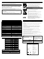
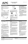
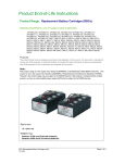
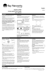
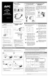
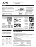
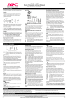
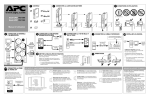
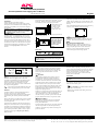
APC PowerStack 250/450
Uninterruptible Power Supply User’s Manual
English
990-5020 Revision 1 10/98
Installation
To obtain warranty coverage, please fill out and
return the warranty registration card now.
Inspection
Inspect the APC PowerStack 250/450
Uninterruptible Power Supply (UPS) upon receipt.
Notify the carrier and dealer if there is damage. The
packaging is recyclable; save it for reuse or dispose
of it properly.
Wall Mounting
The brackets on the UPS can be rotated 90 ° for wall
mounting. Remove the screws, rotate the brackets,
and insert the screws in the appropriate holes.
Wall-mount the unit
with the controls
towards or at the
top, not at the
bottom of the unit .
Warning! Changes or modifications to this unit
not expressly approved by the party responsible
for compliance could void the warranty.
Rack Mounting
The UPS comes with standard 46.5 cm (19") rack
mount brackets. It is supplied with four (4) screws
to attach the mounting brackets (ears) to the chassis.
The illustrations above show the proper positions for
wall mounting the unit
Select a rack location with adequate air flow that is
free from excessive dust. Ensure that the air vents on
the sides of the UPS are not blocked. Do not operate
the UPS where temperature or humidity are outside
the limits in the Specifications section of this
manual.
Do not mount the unit
on the wall as shown
in the illustrations at
left. Doing so could
result in a safety
hazard.
Warning!
Rear View
Desktop Use
This UPS is provided with four adhesive-backed
rubber “feet” for desktop use. Attach the feet to the
bottom of the unit and remove the ears to use it on a
desktop.
The recommended placement of the feet is shown by
a small + on the bottom corners of the unit:
Computer Interface Port
The interface port is used for communicating with
the UPS. See enclosed documentation for details.
Charge the battery pack
The UPS charges its battery pack whenever it is
connected to utility power. The battery pack will
charge fully during the first 4 hours of normal
operation. Do not expect full battery back-up
runtime during this initial charge period.
Once the UPS is mounted, please follow the
installation instructions in the Smart-UPS Quick
Reference Guide.
Operating Instructions
Switch On — Switch Off
With the UPS plugged in, press and release the
on/off/test button to supply power to the loads.
The loads are immediately powered while the UPS
performs a self-test. Press and release the button
again to turn off power to the loads. It may be
convenient to use the UPS as a master on/off switch
for the protected equipment.
The green on-line LED illuminates when the
UPS is supplying utility power to the loads.
Self-test
The UPS performs a self-test automatically when
turned on, and every two weeks thereafter.
Automatic self-test eases maintenance requirements
by eliminating the need for periodic manual selftests.
During the self-test, the UPS briefly powers the loads
on-battery. If the UPS passes the self-test, it returns
to on-line operation.
If the UPS turns off during the self-test and emits a
fading tone, the batteries are not connected properly.
The loads are not affected by a failed test. Recharge
the battery pack overnight and perform the self-test
again. If the replace battery LED is still on, replace
the battery pack using the Replacing the Battery
Pack procedure.
On Battery
During on-battery operation, the yellow on-battery
LED illuminates and the UPS sounds an audible
alarm consisting of 4 beeps every 30 seconds. The
alarm stops when the UPS returns to on-line
operation.
Overload
When loads exceed the UPS’s capacity, the red
overload LED illuminates and the UPS emits a
sustained tone. The alarm remains on until the
overload is removed. Disconnect nonessential load
equipment from the UPS to eliminate the overload.
If the overload is severe, the input circuit breaker
may trip (the resettable center plunger of the circuit
breaker pops out). Disconnect nonessential load
equipment from the UPS to eliminate the overload
and press the plunger back in.
If there is AC power and the circuit breaker does not
trip during overload, the loads are still powered. If
the circuit breaker trips or the UPS attempts to
transfer to battery, the loads’power will be shut off.
Turn the UPS off then back on to power the loads.
Low Battery
When the UPS is operating on-battery and the
energy reserve of the battery pack runs low, the UPS
beeps continuously until the UPS shuts down from
battery pack exhaustion or returns to on-line
operation, if the utility power returns before the
battery pack is exhausted..
Cold Start
Note: Cold start is not a normal operating
condition.
When the UPS is off and there is no utility power, it
is possible to cold start the UPS to power the loads
from the UPS’s battery pack.
·
Press and hold the on/off/test button until the
UPS emits a constant tone.
· Release the on/off/test button during the tone to
start the UPS.
Replace Battery
If the battery pack fails a self-test, the UPS emits
short beeps for one minute and the red replace
battery LED illuminates.
The UPS repeats the alarm every five hours. Perform
the self-test procedure to confirm replace battery
conditions. The alarm stops when the battery pack
passes the self-test.
Storage
Storage Conditions
Before storing, charge the UPS for at least 8 hours. Cover the UPS and store it lying
flat in a cool, dry location, with its battery pack fully charged.
Extended Storage
At -15 to +30 °C (+5 to +86 °F), charge the UPS’s battery pack every 6 months.
At +30 to +45 °C (+86 to +113 °F), charge the UPS’s battery pack every 3 months.
Replacing the Battery Pack
This UPS has an easy to replace hot-swappable battery pack.
APC
Note: Please read the cautions in the APC Safety Guide.
1.
Reach into the finger pull and remove the front cover.
2.
Use a flat-blade screwdriver to turn the two battery door
screws ¼ turn counterclockwise; open the door.
3. Grasp the clear plastic tab and gently pull the battery pack
out of the UPS until the battery connector is visible.
Warning! Do not force the battery pack out. This may
damage internal wiring!
Replacement Batteries
See your dealer or call the number in this manual for information on replacement
battery pack kits. For 250 models, order RBC17. For 450 models, order RBC18.
Battery Pack Replacement Procedure
Battery pack replacement is a safe procedure, isolated from electrical hazards. You
may leave the UPS and loads on for the following procedure.
4.
Disconnect the battery connector by gripping both sides of
the connector and firmly pulling them apart.
5.
6.
Slide the battery pack out of the UPS.
Slide the new battery pack three-fourths of the way into the
UPS.
Connect the battery connector attached to the unit to the
connector attached to the new battery pack.
Notes
·
Once the battery pack is disconnected, the loads are not protected from
power outages.
·
Be careful removing the batteries - they are heavy.
·
Small sparks at the battery connectors are normal during connection.
7.
8.
Push the battery pack in as far as it will go. There are stops
in the back to prevent it from going too far.
9. Close the battery door, turn the battery compartment screws
¼ turn clockwise, and replace the front cover.
10. Batteries must be recycled. Deliver the battery to an
appropriate recycling facility or ship it to the supplier in the
new battery’s packing material. See the new battery
instructions for more information.
Specifications
Service
250 VA
450 VA
0 - 320 VAC
165 - 283 VAC
208 - 253 VAC
Resettable circuit breaker
47 - 63 Hz (autosensing)
4 ms typical, blackout response time
250 VA 165 W
450 VA 280 W
230 VAC
50 or 60 Hz, ±0.1 Hz; unless synchronized to
utility during brownout
On-battery waveshape
Stepped sine-wave
Output Over Current Protection
Overcurrent and short-circuit protected, latching
shutdown on overload
Battery type
Spill proof, maintenance free, sealed lead-acid
Typical battery life
3 to 6 years, depending on number of discharge
cycles and ambient temperature
Typical recharge time
4 to 8 hours from total discharge
Operating temperature
0 to +40 °C (+32 to +104 °F)
Storage temperature
-15 to +45 °C (+5 to +113 °F)
Operating and storage relative humidity
5 to 95%, non-condensing
Operating elevation
0 to +3,000 m (0 to +10,000 ft)
Storage elevation
0 to +15,000 m (0 to +50,000 ft)
Audible noise at 1 m (3 ft)
<38 dBA
Size (H x W x D)
4.5 x 44.5 x 33 cm.
(1.75 x 17.5 x 13.0 in.)
Weight - net (shipping)
8.41 (10.45) kg.
9.77 (11.82) kg.
18.5 (23) lbs.
21.5 (26) lbs.
Safety and approvals
VDE licensed to EN50091 and EN60950
EMC certification
EN55022
Electromagnetic Immunity
IEC 801-2 Level IV, 801-3 Level III,
801-4 Level IV
¬ User adjustable through PowerChuteÒ plus (see software documentation)
Acceptable input voltage
Input voltage (on-line operation) ¬
Output voltage ¬
Input Over Current Protection
Frequency limits (on-line operation)
Transfer time
Maximum load
On-battery output voltage
On-battery frequency
LEDs and Audible Alarms
Function
LED
Tone*
UPS is on
l
m
l
l
—
UPS is running on battery
m
l
—
—
4
UPS is performing self-test
m
X
l
l
—
Overload
—
—
m
—
1
Overload shutdown
—
—
m
—
1
Output short circuit
—
—
m
—
1
—
m
—
1
Transformer failure
—
Low Battery (while on battery)
m
—
—
—
Replace battery condition
—
—
—
m
2
Battery disconnected in self test
l
l
l
l
3
X
X
X
X
X
l
l
1
X
X
X
1
—
—
1
If the UPS requires service do not return it to the dealer! Follow these steps:
1.Use the Troubleshooting section of the Quick Reference Guide to eliminate common
problems.
2.Verify that no circuit breakers are tripped. A tripped circuit breaker is the most common
UPS problem!
3.If the problem persists, call customer service or visit the APC Internet Website
(www.apcc.com).
4.Note the model number of the UPS, the serial number, and the date purchased. A
technician will ask you to describe the problem and try to solve it over the phone, if
possible. If this is not possible the technician will issue a Return Merchandise
Authorization Number (RMA#).
5.If the UPS is under warranty, repairs are free. If not, there is a repair charge.
6.Disconnect the batteries before packing the UPS.
7.Pack the UPS in its original packaging. If the original packing is not available, ask
customer service about obtaining a new set.
8.Pack the UPS properly to avoid damage in transit. Never use Styrofoam beads for
packaging. Damage sustained in transit is not covered under warranty.
9.Include a letter with your name, RMA#, address, copy of the sales receipt, description of
the trouble, your daytime phone number, and a check (if necessary).
10.Mark the RMA# on the outside of the package.
11.Return the UPS by insured, prepaid carrier to the address given to you by Customer
Service.
North & Latin America
APC
132 Fairgrounds Road
West Kingston, Rhode Island 02892
USA
1-800-800-4APC/1-401-789-5735
Internet: http://www.apcc.com
E-Mail:
E-Mail:
North America: [email protected]
Europe: [email protected]
Latin America: [email protected]
Declaration of Conformity
Application of Council Directives:
Standards to Which Conformity Declared:
Manufacturer's Name and Address:
UPS internal alarms:
boost/trim failure
transfer relay weld
Sleep Mode
—
Importer's Name and Address:
Type of Equipment:
Model Numbers:
Key:
— = irrelevant to condition
m = on steady
X = flashing
l = Off
Serial Numbers:
*
1 = sustained tone
2 = 1 minute of beeping every 5 hours
3 = fading tone
4 = 4 beeps every 30 seconds
Europe
APC
Ballybritt Business Park
Galway, Ireland 1800-702000
Toll-free within the Republic
of Ireland only
Years of Manufacture:
Note:
89/336/EEC,73/23/EEC,92/31/EEC,
93/68/EEC,91/157/EEC
EN55022, EN50082-1, EN50091, EN60950
American Power Conversion
132 Fairgrounds Road
West Kingston, Rhode Island, 02892, USA
-orAmerican Power Conversion (A. P. C.) b. v.
Ballybritt Business Park
Galway, Ireland
-orAmerican Power Conversion Phillipines
Second Street
Cavite EPZA
Roserio, Cavite Phillipines
American Power Conversion (A. P. C.) b. v.
Ballybritt Business Park
Galway, Ireland
Uninterruptible Power Supply
PowerStack Models250 and 450, BayStack
Model UPS45
X9801 000 0000 — X9899 999 9999*
X9901 000 0000 — X9999 999 9999*
1998, 1999
Where X = B, O, W, or D
We, the undersigned, hereby declare that the equipment specified above conforms to the above directives.
Billerica, MA
Place
10/1/98
Date
Galway, Ireland
Place
10/1/98
Date
Stephen A. Lee
Regulatory Compliance Engineer
Ray S. Ballard
Managing Director, Europe