1
US 20120232703A1
(19) United States
(12) Patent Application Publication (10) Pub. No.: US 2012/0232703 A1
(43) Pub. Date:
Moore et al.
(54)
RAPID PROGRAMMING OF THERMOSTAT
(75)
Inventors:
Publication Classi?cation
(51)
Glenn A. Moore, Geneva, IL (US);
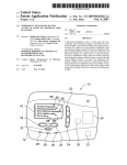
Daniel PoplaWski, OsWego, IL
(US); Robert M. Rados, Yorkville,
IL (US)
Sep. 13, 2012
(52)
(57)
Int. Cl.
G05D 23/19
G06F 3/048
(2006.01)
(2006.01)
Us. or. ....................................... .. 700/278; 715/772
ABSTRACT
The invention provides for a controller such as a thermostat
(73) Assignee:
Braeburn Systems, LLC,
Montgomery, IL (US)
for an HVAC system comprising a housing having a circuit
board and a display screen, the display screen having at least
one alpha-numeric icon and a group of input control areas. A
microprocessor is provided for controlling the display screen.
(21) Appl. No.:
(22)
Filed:
13/045,370
Mar. 10, 2011
Buttons are pressed in order to program set-points of the
thermostat so that seven days may be programmed simulta
neously. The display includes a seven day icon so that the user
can program the thermostat set-points rapidly (e.g. setting
time and temperature settings With minimal steps).
Patent Application Publication
Sep. 13, 2012 Sheet 1 0f 4
US 2012/0232703 A1
“unam
Patent Application Publication
Sep. 13, 2012 Sheet 2 0f 4
US 2012/0232703 A1
Patent Application Publication
Sep. 13, 2012 Sheet 3 0f 4
US 2012/0232703 A1
Patent Application Publication
Sep. 13, 2012 Sheet 4 0f 4
m
‘31.0% .3 .
kswslzi
US 2012/0232703 A1
Sep. 13,2012
US 2012/0232703 A1
RAPID PROGRAMMING OF THERMOSTAT
button and a touch sensitive area button. In an embodiment, a
mechanical button may be a rocker sWitch.
[0006] In an embodiment, the method may comprise the
step of selecting the temperature and duration for a fractional
day period, such as a morning period, a daytime period, an
[0001] The present invention pertains to a display and
method for rapid programming of a thermostat in order to
control multiple functions of an HVAC system controlled by
evening period, a night period, occupied period or unoccu
the thermostat.
pied period. In an embodiment, the method may further com
prise the step of selecting a fan setting.
BACKGROUND
[0002] Thermostats typically have multiple functions that
require user input, such as setting time of day, day of Week,
programming temperature set points or programming user
settings. Control panels typically include an assortment of
buttons for operating the thermostat and adjusting the set
tings. Adjustment of the thermostat settings using the assort
ment of buttons can often times be confusing to the user,
require detailed revieW of user manual and consume much
time in order to properly operate the thermostat and adjust the
settings to the user’s liking.
[0003] In some cases a liquid crystal display (LCD) may be
provided that includes touch sensitive areas populated on the
display screen. The touch sensitive area may include numer
als, Word phrases or graphics (collectively, “icons”) that
appear on the display screen. By touching the appropriate
icon, the user can make adjustments to the functioning of the
thermostat and activate speci?c modes of operation or make
setting adjustments. Some thermostats are knoWn to have
mechanical buttons or sWitches (“hard buttons”). Such hard
buttons are commonly used in combination With touch sen
sitive areas (“soft buttons”) on a LCD. Some thermostats have
[0007] The present invention may further comprise a ther
mostat display for programming a thermostat comprising a
thermostat including a system button and a program button, a
display screen including a seven day icon, a temperature icon
and a time icon, Wherein activation of the program button
selects the seven day icon and activation of the system button
provides for selection of one of a heat mode and a cool mode
and for programming all seven days simultaneously for one of
the modes by adjustment of the temperature and time icons.
[0008] In an embodiment, the seven day icon may comprise
an alpha-numeric representation of each of the seven days of
the Week. In an embodiment, the icon may comprise “M TU
W TH E SA SU.” In an embodiment, the temperature and time
icons may comprise an alpha-numeric representation. In an
embodiment, a rocker sWitch may be provided for adjusting
set points for temperature and time of the modes. In an
embodiment, a fan button may be provided for selecting a fan
mode for the heat and cool modes.
[0009] In an embodiment, the program button may include
a pre-determined time trigger so that pressing the program
button for a period of time greater than the pre-determined
time trigger results in activation of a seven day programming
mode and pressing the program button for a period of time
multiple hard buttons on different portions of the thermostat
housing. Typically the user must program the thermostat by
using the soft or hard buttons to adjust set-points (e.g. time
of an individual day programming mode. In an embodiment,
the system button and program button may be touch sensitive
and corresponding temperature) for each day of the Week.
The process of programming is typically repeated seven times
areas displayed on the display screen of the thermostat.
[0010] The present invention may also provide for a com
so that the proper set-points are programmed for each Week
puter readable media having stored thereon computer execut
able instructions for programming a thermostat, the instruc
less than the predetermined time trigger results in activation
day and Weekend day. When programming includes setting
hour, minute, temperature and fan settings: the total number
steps and inputs required to complete the programming for
tions, When executed by a computing device, perform the
steps comprising displaying a system button, displaying a
seven days may exceed 100 steps. The present invention
overcomes many of the above mentioned disadvantages of
previously knoWn thermostats and alloWs for more rapid pro
program button, displaying a seven day icon, displaying a
time icon, displaying a temperature icon, selecting the seven
day icon upon activation of the program button, selecting one
gramming of the thermostat.
SUMMARY
[0004] The present invention provides for a method for
programming a thermostat comprising the steps of providing
a thermostat having a display and buttons for controlling at
least tWo modes of a thermostat, including a heating mode
and a cooling mode and a thermostat capable of controlling
the heating and cooling modes for each of seven days, acti
vating a ?rst programming mode in order to select all seven
days simultaneously, displaying a seven day icon on the dis
play during the heating mode selection, activating a second
programming mode in order to select all seven days for the
cooling mode for all seven days simultaneously, and display
ing the seven day icon on the display during the cooling mode
selection.
[0005] In an embodiment, the buttons may be mechanical
buttons disposed on a housing of the thermostat. In an
embodiment, the buttons may be touch sensitive areas dis
played on a display screen of the thermostat. In an embodi
ment, the buttons may be a combination of a mechanical
of the heat mode or cool mode upon activation of the program
button and simultaneously programming seven days for the
heat mode or cool mode by adjusting set points via the time
and temperature icons.
[001 1] In an embodiment, the seven day program may com
prise an alpha numeric representation of each of the seven
days of a Week. In an embodiment, the time and temperature
icons may comprise an alpha-numeric representation. In an
embodiment, a rocker sWitch for adjusting the set points for
temperature and time modes may be provided for a period. In
an embodiment, the complete programming of the seven days
for the heating or cooling may be provided Without requiring
an increment from a ?rst day to a second day during user input
to program the thermostat.
BRIEF DESCRIPTION OF THE DRAWINGS
[0012]
For a better understanding of the subject invention,
reference may be had to embodiments shoWn in the attached
draWings in Which:
[0013]
tion;
FIG. 1 is a schematic diagram of the present inven
Sep. 13, 2012
US 2012/0232703 A1
[0014]
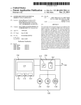
FIG. 2 is a plan vieW ofa thermostat of the present
is an indication of the current room temperature and is indi
invention;
cated as such by the “ROOM” icon 110. As Well, an alpha
[0015] FIGS. 3-4 are diagrammatic vieWs of the display
screen illustrating examples of operation of the present inven
tion; and
[0016] FIG. 5 is How diagram of the present invention.
numeric icon is indicating that the HVAC cooling system is
DETAILED DESCRIPTION
[0017] An embodiment of the present invention is depicted
With respect to the folloWing FIGS. 1-5, and in particular an
overvieW of the electronic circuitry and components of the
thermostat 10 of the present invention Will be described With
respect to FIG. 1. The thermostat 10 includes a display 12
(including touch sensitive area 13), a microprocessor 14 and
sWitch 20. SWitch 1 is provided, Which may be opened and
closed in order to signal the microprocessor 14 (eg to incre
ment the selected set-point). As Well a SWitch 2, is provided
Which may be opened or closed to signal the microprocessor
14 (eg to decrement the selected set-point). The micropro
cessor controls the HVAC system 21 attached to the thermo
stat 10 and also is connected to the display 12, Which alloWs
for user input to adjust the system. For example, in a typical
HVAC system 21, the thermostat 10 Would be used to adjust
the heating or cooling of the system in order to provide a
comfortable environment for the occupants. The micropro
cessor 14 includes ROM Which may have software loaded
into it, in order to control the thermostat 10 and to provide for
the display screen functionality. The display screen 12
includes displayable touch sensitive areas (see FIG. 2). As
Will be discussed in greater detail beloW, the combination of
the actuation of SWitch 1 and SWitch 2 (via the rocker sWitch
20) and the touch sensitive areas 13 on the display screen 12
alloW the microprocessor 14 to monitor and control the air
handler HVAC system 21 or any other system to Which the
thermostat 10 is connected.
[0018]
The physical construction of the invention is
running as indicated by the “COOL ON” icon 115. Other
numeric icons 110 are displayed including “70” Which is
displayed beloW the alpha-numeric icon “SET AT” 117; so
“70” is the set point at Which the thermostat is set to trigger the
HVAC system. Numeric icon “12:00” (119) indicates a set
point at Which the temperature should be at 70 degrees.
According to the alpha-numeric icon “TU MORN” 122 indi
cating that on Tuesday mornings at 12:00 p.m., the set point
should be 70 degrees Fahrenheit. The display of the “TU
MOR ” icon 122 indicates that a single/day programming
mode has been selected by depressing the “SYSTEM” touch
sensitive area 152 for less than three seconds.
[0020] The graphical icon 140 in this embodiment is a
representative pictorial of a fan blade and indicates that the
fan mode is on and running. Other types of graphical icons
may be provided on the display 12.
[0021] Other alpha-numeric icons 120 are included Within
touch sensitive area 150a, 1501). For example, as depicted on
the display 12 in the embodiment of FIG. 2, the touch sensi
tive area 150a, 1501) that are provided and designated With
alpha-numeric icons 120 are “CLEAN” “CONFIG”
“HUMIDITY” “OUTDOOR” “SYSTEM” “FAN” “PROG”
(PROGRAM) “HOLD” “DAY/TIME”. In the embodiment
depicted in FIG. 2, the touch sensitive area 150a, 1501) are
designated by rectangular outlines provided the display
screen 12. In an alternate embodiment, the display screen 12
may have no touch sensitive areas and may function solely to
display alpha-numeric 120, graphical 140, and numeric icons
110. In such an alternate embodiment the housing may
include the rocker sWitch 20 and other mechanical buttons to
operate the thermostat. For example, a ?rst mechanical button
for the menu or system function and a second mechanical
button for the program function may be provided adjacent the
described With respect to FIG. 2 as folloWs. A thermostat 10
or controller includes a display screen 12 and a printed circuit
rocker sWitch 20.
board mounted Within a housing. A rocker sWitch (mechani
cal button) 20 is formed of a longitudinal bar having a ?rst end
sensitive area 150a, 150!) displayed on the display screen 12,
are sensing areas provided by a touch sensitive area above the
display screen 12. For example, in the display for the touch
sensitive area on the right side of the display screen 12 (in
cluding “CLEAN” “CONFIG” “HUMIDITY” “OUT
DOOR” forming a roW of four icon touch sensitive area 5011,
15019), a single long touch activation area on the touch mem
22 and a second end 23. The thermostat 10 includes a front
face. The rocker sWitch 20 is mounted so that the sWitch
button is exposed in the front face 17 and may be easily
operated by a user. As shoWn in FIG. 2, the thermostat 10 is
oriented so that the ?rst end 22 of the rocker sWitch 20 is
oriented at the upper portion of the thermostat 10 and the
second end 23 of the rocker sWitch 20 is located toWard the
loWer portion of the thermostat. In this orientation, the rocker
sWitch 20 may provide for the ?rst end 22 to act as the “up”
incrementation or adjustment of a set point and the second
end 23 indicates “doWn” decrementation or adjustment of a
set point. The rocker sWitch 20 may also adjust modes of the
thermostat 10 by rocking the sWitch to the “up” position by
depressing the ?rst end 22 or “doWn” position by depressing
the second end 23 . A housing 31 supports the rocker sWitch 20
and display 12.
[0019] Turning to FIGS. 2-4, the standard operations of the
thermostat Will be described in further detail. FIG. 2 depicts
the thermostat 10 including the display screen 12 having
[0022]
As depicted in FIG. 2, coincident With the touch
brane above the screen layer 12 Will be provided. LikeWise,
on the left side of the display screen 12, an “L” shape touch
sensitive area on the membrane beloW the touch screen layer
12 Will be provided over the touch sensitive area 150a, 1501)
on the display screen 12 (coinciding With the “SYSTEM”
“FAN” “PROG” “HOLD”AND “DAY/TIM” icons). Thus in
the embodiment described above, it may be understood that
there is no touch sensing capabilities in the center of the
display screen 12, Where the numeric icons 110 for the current
room temperature set point, or time set point are displayed. In
the embodiment, depicted in FIG. 2 the alpha-numeric icons
120 provided in each of the touch sensitive area 150a, 1501)
are modes of operation for the thermostat 10. Generally
icon 140. Also included on the display, are touch sensitive
speaking, the modes of operation may be activated by touch
ing the display screen 12 associated With the particular mode,
as identi?ed by the alpha-numeric icons 120. For example,
the action of the user’s ?nger applied to the display screen 12
(input control) areas 150a, 150b, 1500 (FIG. 3, 4). In the
at the area identi?ed by the alpha-numeric icon “CLEAN”
embodiment displayed in FIG. 2, the numeric icon “70” 110
120 bounded by the rectangle indicating the touch sensitive
multiple icons displayed thereon. The display includes
numeric icons 110, alpha-numeric icons 120 and graphical
Sep. 13,2012
US 2012/0232703 A1
area 150a will activate the “CLEAN” mode and allow for
setting of the ?lter cleaning mode or reminder.
[0023] In an embodiment, the touch sense regions of the
touch sensitive membrane below the touch sensitive area
1501) for “SYSTEM” and “FAN” will not be touch reactive.
For example, when the “SYSTEM” touch sensitive area 1501)
icon 124 will be displayed on the display 12. In the embodi
ment depicted in FIG. 3, the seven day programming icon 124
is “M TU W TH E SA SU”, which indicates each of the seven
days of the week simultaneously. Other seven day program
ming icons may be provided such as a “7 DAY” or calendar
icon. Therefore, when the seven day programming mode icon
is pressed, the “AUTO” alpha-numeric icon will be high
124 is displayed the user will understand that he or she is
lighted or made bold to indicate that the automatic feature of
programming the time and temperature set points for each of
the system has been activated. Likewise, when the “SYS
TEM” touch region 1501) is pressed a second time by a user’s
the seven days of the week simultaneously. In an embodi
ment, the user may program all of the morning times simul
?nger, the alpha-numeric icon 120 “COOL” will be displayed
taneously when the “MORN” icon 125 is displayed. Other
as being activated. Such activation may be indicated by mak
icons such as “DAY”, “EVE”, and “NIGHT” will be dis
ing the “COOL” alpha-numeric icons 120 bold. However, in
the “AUTO” alpha-numeric icon 120 is displayed below the
played in order to allow for rapid programming by a fractional
period such as the daytime, evening or night periods. A ?rst
event is selected by touching the “SYSTEM” button 152 to
select “HEAT” mode (for winter) or “COOL” mode (for
“FAN” touch area 1501) is not touch sensitive.
summer).
[0024]
[0027] In a commercial programming mode, the time and
temperature set points may be adjusted for a fractional period
this embodiment, neither the “AUTO” or “COOL” area of the
display screen 12 is touch sensitive. Similarly, the area where
The initial setting of the thermostat 10 involves con
?guration of installer settings in the embodiment disclosed in
FIG. 2. The installer settings are selected by pressing the
“SYSTEM” button 152 and “CONFIG” button 154 simulta
neously. By holding down the buttons, 152, 154 simulta
neously for three seconds the installer settings mode will be
activated. It is noted that the term “button” refers to the
combination of the alpha-numeric icon (for example, “SYS
such as an “OCCUPIED” or “UNOCCUPIED” period. Fol
lowing selection of the “HEAT” or “COOL” mode, the
“OCCUPIED” period/event time and temperature can be pro
grammed and the “OCCUPIED” icon 167 can be pro
grammed and the “OCCUPIED” icon will be displayed (FIG.
4). Thereafter, the “UNOCCUPIED” period/event may be
TEM”) and the touch sensitive area 150 designated by the
rectangular outline of the pad. “Soft” button refers to those
programmed and an “UNOCCUPIED” icon can be dis
buttons located on the touch screen display 12 and “HARD”
button refers to a button separate from the touch screen dis
[0028] The microprocessor 14 advances the display logic to
Step D, which provides for the alpha-numeric icon 160 indi
cating the set point for the time of day. The alpha-numeric
play (i.e. the rocker switch 20).
[0025]
Turning to FIGS. 3-5, the operation of the seven
day/whole week programming functionality of the present
invention will be described. The ?ow chart of FIG. 5 indicates
the steps A-K followed by the thermostat 10 and the displays
for such corresponding operations are depicted in FIGS. 3 and
4. Step A requires the user to activate the “PROG” touch
sensitive area 156 in order to select the individual day pro
gramming mode or the seven day programming mode. The
played.
icon 160 will ?ash (eg on and off, or lighter and darker) to
identify for the user that the time of day may be adjusted. As
depicted in FIG. 3, the alpha-numeric icon 160 is a display of
the time “6:00” “am.” and the numeral “6” is ?ashing along
with the “am.” ?ashing to indicate that the user may adjust
the hour set-point. In an embodiment, the set point for the
time may be adjusted by pressing the rocker switch 20 (FIG.
2). Once the user is satis?ed with the set point for the time as
system is programmed to include a pre-determined time trig
indicated by the alpha-numeric icon 160, the user will press
ger with respect to the duration that the program button 156 is
the “NEXT” touch sensitive area 155. In an embodiment, the
“PROG” button 156 will disappear once the seven day pro
depressed. In an embodiment, the predetermined time trigger
is set for 3 seconds. If the program button is depressed for less
than 3 seconds. Step B is triggered and there is a call for the
individual day programming routine and the individual day
icon 122 (as shown in FIG. 2) will appear on the display 12,
so that the user may program the time and temperature set
points as the display is incremented day by day. As discussed
above, the individual day programming mode will be more
time consuming than the seven day programming mode.
However, if each day of the week requires different set points,
then the user may prefer to implement the individual day
programming mode Step B. If for each day of the week the
user must determine and input set points for each day using
the “DAY/TIME” button 154 and adjusting the hour, minute,
temperature and fan settings, the number of decisions the
consumer must consider could require more than one hundred
inputs. In order to avoid such lengthy programming time, the
present invention provides for the seven day programming
mode Step C.
[0026]
When the “PROG” touch sensitive area 156 is
gramming (Step D) begins (as shown in FIG. 4).
[0029] Step E is initiated by ?ashing the minute icon 160
(eg “00”). In an embodiment, the minutes may be adjusted in
ten minute increments by depressing the rocker switch 20
(FIG. 2). When the “NEXT” touch sensitive area 155 is
pressed the selected item will stop ?ashing. After the minutes
are set to the appropriate time setting the user will press the
“NEXT” touch sensitive area 155 to advance to the next step.
Pressing the “BACK” touch sensitive area 157 will allow for
navigation backwards. In an embodiment, the system will
return to home or normal mode if no button is pressed for 30
seconds.
[0030]
Step F is implemented by the ?ashing of the tem
perature alpha-numeric icon 165, as shown in FIG. 4. The
?ashing of the temperature icon 165 demonstrates to the user
that he or she may program the set point for the temperature
for each of the seven days. In an embodiment, the temperature
may be adjusted in 1° F. or 0.5° C. increments by pressing the
rocker switch 20 (FIG. 2). As depicted in FIG. 4, the tempera
depressed for a duration longer than the predetermined time
ture is indicated as “75” or 75 degrees Fahrenheit (Celsius
(eg 3 seconds), a call is made to initiate the seven day
programming mode (Step C). Once the user selects the seven
mode may also be provided).
[003 1] Once the set point for the temperature is appropriate,
day programming mode, the seven day programming mode
the user may press the “NEXT” touch sensitive area 155 to
Sep. 13,2012
US 2012/0232703 A1
move to Step G in order to adjust the fan setting. As discussed
above, the “FAN” icon may ?ash or provide some other type
of icon indicating that that icon may be adjusted via the
pressing of buttons on the thermostat 10. After the fan setting
is adjusted, the user presses the “NEXT” touch sensitive area
155 to advance to the next step in the sequence.
[0032]
At Step H, the system determines Whether more
events need to be programmed. For example, if the user has
just completed setting for the “MORN” period, the next event
may be to set the “DAY” period. Then the sequence of steps to
adjust the hour Will begin again at Step D, subsequently
folloWed by the adjustment of the set points at Steps E-G.
Again at Step H, the system Will determine if there are any
more events to program.
[0033]
If there are no more events to program the next step
is to exit the seven day programming mode at Step J by
completing a 30 second timeout, or by pressing the
“RETURN” button 1500, Which Will cause the home screen to
be displayed. For example, the display 12 as depicted in FIG.
2 may be displayed. Then at Step K, the programming has
ended and the user may alloW the thermostat to run automati
cally according to the set points inputted. Thus it can be
understood that in less than tWenty steps via use of the seven
day programming mode, the entire Week Worth of set points
can be programmed into the thermostat. This programming
can be undertaken Without requiring an increment from a ?rst
day to a second day etc. (such as required during the indi
vidual day programming mode). In an embodiment, the sys
tem may provide for a ?ve day programming mode (eg a 5-2
day residential or commercial mode for Monday-Friday
using one 4 event schedule and Saturday and Sunday pro
grammed With a different 4 event schedule).
[0034] While various concepts have been described in
detail, it Would be appreciated by those skilled in the art that
various modi?cations and alternatives to those concepts
could be developed in light of the overall teachings of the
disclosure. Therefore, a person skilled in the art, applying
ordinary skill, Will be able to practice the invention set forth in
the claims Without undue experimentation. It Will addition
ally be appreciated that the particular concepts exposed
herein are meant to be illustrative only and not limiting to the
scope of the invention, Which is to be given the full breath of
the appended claims and any equivalents thereof.
2. The method of claim 1 Wherein:
the buttons are mechanical buttons disposed on a housing
of the thermostat.
3. The method of claim 1 Wherein:
the buttons are touch sensitive areas displayed on a display
screen of the thermostat.
4. The method of claim 1 Wherein:
the buttons are a combination of a mechanical button and
touch sensitive area button.
5. The method of claim 1 Wherein:
the mechanical button is a rocker sWitch.
6. The method of claim 1 further comprising the step of:
selecting the temperature and duration for a fractional day
period including one of a morning period, a daytime
period, an evening period, a night period, an occupied
period or an unoccupied period.
7. The method of claim 1 further comprising the step of:
selecting a fan setting.
8. A thermostat display for programming a thermostat
comprising:
a thermostat including a system button and, a program
button;
a display screen including a seven day icon, a temperature
icon and a time icon Wherein activation of the program
button selects the seven day icon; and
activation of the system button provides for selection of
one of a heat mode and cool mode and for programming
of all seven days simultaneously for one of the modes by
adjustment of the temperature and time icons.
9. The display of claim 8 Wherein:
the seven day icon comprises an alphanumeric representa
tion of each of the seven days of a Week.
10. The display of claim 8 Wherein:
the seven day icon comprises M, TU, W, TH, F, SA and SU.
11. The display of claim 8 Wherein:
the temperature and time icons comprise an alphanumeric
representation.
12. The display of claim 8 further comprising:
a rocker sWitch for adjusting set points for temperature and
time for the modes.
13. The display of claim 8 further comprising:
a fan button for selecting a fan mode for the heat and cool
modes.
What is claimed is:
1. A method for programming a thermostat comprising the
steps of:
providing a thermostat having a display and buttons for
controlling at least tWo modes of the thermostat includ
ing a heating mode and a cooling mode and the thermo
stat capable of controlling the heating and cooling
modes for every day of the Week;
activating a ?rst programming mode in order to select
seven days for setting the heating mode for all seven
days simultaneously;
displaying a seven day icon on the display during the
heating mode selection;
activating a second programming mode in order to select
all seven days for setting the cooling mode for all seven
days simultaneously; and
displaying the seven day icon on the display during the
cooling mode selection.
14. The display of claim 8 Wherein the program button
includes a predetermined time trigger so that pressing the
program button for a period of time greater than the predeter
mined time trigger results in activation of a seven day pro
gramming mode and pressing the program button for a period
of time less than the predetermined time trigger results in
activation of an individual day programming mode.
15. The display of claim 8 Wherein the system button and
program button are touch sensitive areas displayed on the
display screen of the thermostat.
1 6. A computer readable media having stored thereon com
puter executable instructions for programming a thermostat,
the instructions, When executed by a computing device, per
forming steps comprising:
displaying a system button;
displaying a program button;
displaying a seven day icon;
displaying a time icon;
Sep. 13,2012
US 2012/0232703 A1
displaying a temperature icon;
18. The media of claim 16 Wherein:
selecting the seven day icon upon activation of the program
the temperature and time icons comprise an alphanumeric
button;
selecting the seven day icon upon activation of the program
representation.
of the program button; and
simultaneously programming seven days for the heat mode
or cool mode by adjusting set points via the time and
temperature icons.
19. The media of claim 16 further comprising:
a rocker sWitch for adjusting set points for temperature and
time for the modes.
20. The media of claim 16 Wherein complete programming
of seven days for heating or cooling may be provided Without
requiring an increment from a ?rst day to a second day during
17. The media of claim 16 Wherein:
user input to program the thermostat.
button;
selecting one of a heat mode or cool mode upon activation
the seven day icon comprises an alphanumeric representa
tion of each of the seven days of a Week.
*
*
*
*
*