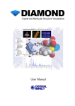
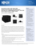
1
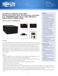
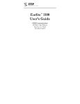
HE-HP2 Manual
High Efficiency
Vehicle Power Supply
DC to DC Converter
Technical Manual
P/N: HE-HP2-MAN
Revision: 30 Jun 2009
Revision
Date
A
4/26/2009
Comment
Initial version
FOR TECHNICAL SUPPORT
PLEASE CONTACT:
[email protected]
Copyright
© June 2009
Copyright
2009
Diamond Systems Corporation
1255 Terra Bella Ave.
Mountain View, CA 94043 USA
Tel 1-650-810-2500
Fax 1-650-810-2525
www.diamondsystems.com
CHAPTER 1
- INTRODUCTION...................................................................................................4
1.1 GENERAL DESCRIPTION ........................................................................................................................................... 4
1.2 SPECIFICATIONS ........................................................................................................................................................ 6
CHAPTER 2
CONFIGURATION AND INSTALLATION ...............................................................7
2.1 INTRODUCTION ................................................................................................................................................................ 7
2.2 POWER CONSIDERATIONS. .............................................................................................................................................. 8
2.2.1 Main Input Power Connector............................................................................................................................. 8
2.2.2 Output Power Connector................................................................................................................................... 8
2.2.3 Ignition input ...................................................................................................................................................... 8
2.3 JUMPER SELECTION ........................................................................................................................................................ 9
2.3.1 LED Jumper Enable/Disable ............................................................................................................................. 9
HE-HP2 User Manual Rev A
www.diamondsystems.com
Page 2
PREFACE
This manual is for integrators of applications of embedded systems. It contains information on hardware requirements
and interconnection to other embedded electronics.
DISCLAIMER
Diamond Systems makes no representations or warranties with respect to the contents of this manual, and specifically
disclaims any implied warranties of merchantability or fitness for any particular purpose. D iamond Systems shall under no
circumstances be liable for incidental or consequential damages or related expenses resulting from the use of this product,
even if it has been notified of the possibility of such damages. D iamond Systems reserves the right to revise this publication
from time to time without obligation to notify any person of such revisions. If errors are found, please contact D iamond
Systems at the address listed on the title page of this document.
COPYRIGHT © 2009 Diamond Systems
No part of this document may be reproduced, transmitted, transcribed, stored in a retrieval system, or translated into any
language or computer language, in any form or by any means, electronic, mechanical, magnetic, optical, chemical,
manual, or otherwise, without the express written permission of D iamond Systems .
HE-HP2 User Manual Rev A
www.diamondsystems.com
Page 3
CHAPTER 1 - INTRODUCTION
1.1 GENERAL DESCRIPTION
The HE-HP2 is a high efficiency, high performance DC to DC 100 watt converter that supplies +5V
and +12V outputs. The HE-HP2 is designed for low noise embedded computer systems, has a wide
input range of 6-40V(>6:1) and is ideal for battery or unregulated input applications. The HE-HP2 is
specifically designed for vehicular applications and has three heavy-duty transient suppressors
(providing 9000W of protection) on each of the main and secondary power inputs that clamp the input
voltage to safe levels, while maintaining normal power supply operation.
The HE-HP2 is a state-of-the-art Mosfet based design that provides outstanding line and load
regulation with efficiencies up to 90 percent. Organic Semiconductor Capacitors provide filtering that
reduces ripple noises below 20mV. The low noise design makes the HE-HP2 ideal for use aboard
aircraft or military applications or wherever EMI or RFI must be minimized. The +5VDC and +12VDC
outputs are controlled by a constant off-time current-mode architecture regulator that provides
excellent line and load transient response.
The HE-HP2 has an opto-isolated on/off input (SD), allowing for remote control.
The HE-HP2 has a PC/104 footprint with PC/104 mounting holes.
provided to a connector block.
HE-HP2 User Manual Rev A
www.diamondsystems.com
All generated voltages are
Page 4
FEATURES
•DC to DC converter for embedded applications.
•“Load Dump” transient suppression on input power supply.
•Operates from 6VDC to 40VDC input.
•PC/104 size and mounting holes.
•100 watt power supply outputs.
•5V and 12V outputs.
•Temperature range -40 to 85C.
•Opto-isolated input for remote operation.
l
l
HE-HP2 User Manual Rev A
www.diamondsystems.com
Page 5
1.2 SPECIFICATIONS
Power Supply Specifications
Model
HE-HP2
5V output*
20 A
12V output
2.5 A
Input Voltage Range
6 to 40V
Load Regulation**
< 60mV
Line Regulation
40mV
Output temp. drift**
< 40mV
Switching Freq.
75kHz
Max. Input Transient
125V for 100msec
Output Ripple**
< 20mV
Conducted Susceptibility**
> 57db
Efficiency
Up to 95%
Temp. Range
-40 to 85C
Quiescent current***
1.3 mA
Size, PC/104 form factor compliant*** 3.55”W. x 3.75”L. x 0.6”H.
*Current rating includes current supplied to 12Vregulators.
**Measured on the 5V output.
***LED’s disabled.
HE-HP2 User Manual Rev A
www.diamondsystems.com
Page 6
CHAPTER 2
CONFIGURATION AND INSTALLATION
2.1 Introduction
This chapter describes the configuration and installation of the HE-HP2 power supply. In addition,
section 2.2 provides a formula to calculate the available +5VDC. Figure 2-1 shows the HE-HP2
connectors, jumpers and other options.
l
l
HE-HP2 User Manual Rev A
www.diamondsystems.com
Page 7
2.2 Power Considerations.
The +5V switching regulator is rated at 20A maximum output, however the +5V output supplies power
to the +12 VDC regulators. To obtain the usable range of +5V output, “derate” according to the use
of +12VDC. Use the following formulae to calculate the maximum usable output.
I [12] * 2.4
Usable + 5Voutput = 20 A −==
0.9
Where:
I[12] = 12VDC current load
Assuming 90 percent converter efficiency (actual efficiency may vary).
2.2.1 Main Input Power Connector
Input power of 6VDC to 40VDC is connected to the HE-HP2 by two removable connector block CN1
and CN6. Power should be connected to both CN1 and CN6 to prevent exceeding the connector
current limits.
Unregulated vehicle power 6VDC to 40VDC is connected as follows:
-
CN1, Terminal 1:“hot” polarity
CN1, Terminal 2: Common (0VDC)
CN6, Terminal 1:“hot” polarity
CN6, Terminal 2: Common (0VDC)
2.2.2 Output Power Connector
Output power is available via connector blocks CN2, CN3 & CN4. CN2, CN3 & CN4 are located
immediately side-by-side.
-
CN3-1: Position 4, SD (Ignition input, ie maintained contact closure) 6 – 40 VDC input
CN3-2: Position 5, +5VDC output
CN3-3: Position 6, +5VDC output
CN4-1: Position 7, +5VDC output
CN4-2: Position 8, +5VDC output
CN4-3: Position 9, common
CN2-1: Position 10, common
CN2-2: Position 11, common
CN2-3: Position 12, +12VDC output
2.2.3 Ignition input
Output power is applied directly to the power and ground connections on the terminal blocks CN2, 3
and 4.
The HE-HP2 power supply outputs are turned on when 6VDC to 40VDC is applied to the ignition
input signal SD on connector CN3-1.
HE-HP2 User Manual Rev A
www.diamondsystems.com
Page 8
If no remote control is required, this input can be tied to the main input power connector.
Note: SD is an opto-coupled input signal used to turn on/off the outputs. To enable the HE-HP2
outputs, a 6 to 40V signal must be connected to the SD input. The common for the remote 6 to 40V
signal must be connected to the HE-HP2 common. If the SD input is connected directly to the main
input power connector, the common for the SD input is already done.
2.3 Jumper Selection
This section describes the function of each jumper, the location of it, the default setting, and how to
change it.
2.3.1 LED Jumper Enable/Disable
These jumpers allow the LEDs to be disabled. This is to be used when absolute minimum power
consumption must be maintained, such as when operating off a limited battery source.
The location of each LED jumper (JP1 for 5V LED, and JP5 for 12V LED) are shown in the diagram
below.
Each LED is enabled by factory default. To disable any LED, remove the LED jumper (or cut the
small PCB trace if no jumper is installed) associated with the LED. To re-enable any LED, re-install
the associated jumper (or solder a short jumper wire between each of the jumper pads).
HE-HP2 User Manual Rev A
www.diamondsystems.com
Page 9