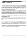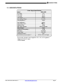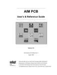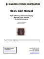
1
HESC-SER Manual
High Efficiency & Smart Charging
Vehicle Power Supply
DC to DC Converter
P/N: HESC-SER MANUAL
Revision: 30 Jun 2009
Revision
Date
A
6/26/2009
Comment
Initial version
FOR TECHNICAL SUPPORT
PLEASE CONTACT:
[email protected]
Copyright
© June 2009
Copyright
2009
Diamond Systems Corporation
1255 Terra Bella Ave.
Mountain View, CA 94043 USA
Tel 1-650-810-2500
Fax 1-650-810-2525
www.diamondsystems.com
CHAPTER 1 - INTRODUCTION ............................................................................................................................................. 4
1.1 GENERAL DESCRIPTION ........................................................................................................................................... 4
1.2 FEATURES ................................................................................................................................................................... 5
1.3 SPECIFICATIONS ........................................................................................................................................................ 6
CHAPTER 2 - CONFIGURATION AND INSTALLATION ...................................................................................................... 7
2.4 INTRODUCTION................................................................................................................................................................ 7
2.4.1 Main Input Power Connector ................................................................................................................................. 8
2.4.2 Output Power Connector ....................................................................................................................................... 8
2.4.3 Battery Connector.................................................................................................................................................. 9
2.4.4 Aux Battery Connector .......................................................................................................................................... 9
2.4.5 RS232 Serial Port Interface................................................................................................................................... 9
2.5 JUMPER SELECTION................................................................................................................................................... 9
2.5.1 LED Jumper Enable/Disable ............................................................................................................................... 10
CHAPTER 3 - USING HESC104 POWER MANAGEMENT FEATURES............................................................................ 11
APPENDIX 1
: EXTERNAL BATTERY DESIGN: ............................................................................................................ 13
1.1 BATTERY ISOLATION...................................................................................................................................................... 13
1.2 DIGITAL SENSOR INTERFACE.......................................................................................................................................... 13
HESC-SER User Manual Rev A
www.diamondsystems.com
Page 2
PREFACE
This manual is for integrators of applications of embedded systems. It contains information on hardware requirements
and interconnection to other embedded electronics.
DISCLAIMER
Diamond Systems makes no representations or warranties with respect to the contents of this manual, and specifically
disclaims any implied warranties of merchantability or fitness for any particular purpose. D iamond Systems shall under no
circumstances be liable for incidental or consequential damages or related expenses resulting from the use of this product,
even if it has been notified of the possibility of such damages. D iamond Systems reserves the right to revise this publication
from time to time without obligation to notify any person of such revisions. If errors are found, please contact D iamond
Systems at the address listed on the title page of this document.
COPYRIGHT © 2009 Diamond Systems
No part of this document may be reproduced, transmitted, transcribed, stored in a retrieval system, or translated into any
language or computer language, in any form or by any means, electronic, mechanical, magnetic, optical, chemical,
manual, or otherwise, without the express written permission of D iamond Systems .
HESC-SER User Manual Rev A
www.diamondsystems.com
Page 3
CHAPTER 1 - INTRODUCTION
1.1 GENERAL DESCRIPTION
The HESC-SER is a high efficiency, high performance DC to DC 60 watt converter that supplies +5V,
-5V, +12V & -12V outputs. The HESC-SER also includes a flash based microcontroller that supplies
advanced power management, smart battery charger and an RS232 serial port. The HESC-SER is
designed for low noise embedded computer systems, has a wide input range of 6-40V(>6:1) and is
ideal for battery or unregulated input applications. The HESC-SER is specifically designed for vehicular applications and has heavy-duty transient suppressors (5000W) that clamp the input voltage to safe
levels, while maintaining normal power supply operation.
The HESC-SER is a state-of-the-art MOSFET-based design that provides outstanding line and load
regulation with efficiencies up to 95 percent. Organic Semiconductor Capacitors provide filtering that
reduces ripple noises below 20mV. The low noise design makes the HESC-SER ideal for use aboard
aircraft or military applications or wherever EMI or RFI must be minimized. The +5VDC and +12VDC
outputs are controlled by a constant off-time current-mode architecture regulator that provides excellent
line and load transient response.
The HESC-SER provides up to four stages of battery charging and can charge Lead-Acid, NiCd, and
NiMh batteries and is also SMBus level 3 compatible. Charge currents are up to 4A, and battery
charging voltages from 9.5 to 35V.
The HESC-SER has advanced power management functions that allow timed on/off control of the
HESC-SER, notification of changes to main power, and changes in the battery status. For example, the
HESC-SER can be programmed to power off the outputs in 60 seconds, and then turn on again 12 hours
later.
The HESC-SER size is 3.55 x 3.775 inches, which is the same size as the PC/104 standard, and has
the same mounting holes pattern as the PC/104 standard. However, the HESC-SER does not supply
the PC/104 bus connectors. (For a PC/104 fully compliant power supply, please see the Diamond
Systems HESC104.) All generated voltages are provided to a Phoenix header. A removable plug
allows the HESC-SER to be easily installed. The RS232 serial port is provided on a 2x5 row pin
header.
The HESC-SER can be configured to meet almost any power supply and battery charging need for
embedded applications, whether that be a simple +5V application, or providing power for back lighted
LCD panels, or a full UPS (un-interruptible power supply configuration).
HESC-SER User Manual Rev A
www.diamondsystems.com
Page 4
1.2 FEATURES
•DC to DC converter for embedded applications.
•“Load Dump” transient suppression on input power supply.
•Operates from 6VDC to 40VDC input.
•PC/104 size and mounting holes.
•60 watt power supply outputs.
•5V, 12V, -12V, -5V, and battery charger outputs.
•Temperature range -40 to 85C.
•Monitors up to 8 external temperatures using I2C digital temperature sensors.
•RS232 serial port for setup, monitoring and control.
•Optocoupled inputs for ignition, and system "shut-down" pushbutton.
HESC-SER User Manual Rev A
www.diamondsystems.com
Page 5
1.3 SPECIFICATIONS
Power Supply Specifications
Model
HESC-SER
5V output*
12 A
12V output
2.5 A
-5V output
400mA
-12V output
500mA
Input Voltage Range
6 to 40V
Load Regulation **
<60mV
Line Regulation **
+40mV
Output temp. drift **
<40mV
Switching Freq.
75kHz
Max. Input Transient
125V for 100msec
Output Ripple**
<20mV
Conducted Susceptibility **
>57db
Efficiency**
up to 95%
Temp Range
-40 to 85C
Quiescent current***
2mA
Size, PC/104 form factor compliant****
3.55"W. x 3.75"L x 0.6"Height
*Current rating includes current supplied to 12V, -12V, & -5V regulators.
**Measured on the 5V output.
***LEDs disabled,
HESC-SER User Manual Rev A
www.diamondsystems.com
Page 6
CHAPTER 2 - CONFIGURATION AND INSTALLATION
2.4 Introduction
This chapter describes the configuration and installation of the HESC-SER power supply. In addition,
section 2.2 provides a formula to calculate the available +5VDC. Figure 2-1 shows the HESC-SER
connectors, jumpers and other options.
Power Considerations.
The +5V switching regulator is rated at 12A maximum output, however the +5V output supplies power
to the +12, -5, and -12VDC regulators. To obtain the usable range of +5V output, “derate” according
to the use of +12, -5, and -12VDC. Use the following formulae to calculate the maximum usable
output.
Where:
( I [ −=
5] +=I [ −=
12] * 2.4 + I [12] * 2.4)
Usable + 5Voutput = 12 A −=
0.9
I[-5] = -5VDC current load
I[-12] = -12VDC current load
I[12] = 12VDC current load
Assuming 90 percent converter efficiency (actual efficiency may vary).
HESC-SER User Manual Rev A
www.diamondsystems.com
Page 7
2.4.1 Main Input Power Connector
Input power is connected to the HESC-SER by a “Molex” plug and pin connector CN6. The power
supply accepts DC input voltages in the range of 6VDC to 40VDC.
Unregulated vehicle power is connected as follows:
- Terminal 1:“hot” polarity
- Terminal 2: Common (0VDC)
2.4.2 Output Power Connector
Output power is available for use via Phoenix MiniCombicon connector. Connectors CN2, CN3 &
CN4 are immediately side by side, with a nine position mating plug-in mating header supplied
-
CN4-1: Position 1, PF (Power Fail signal output) TTL logic level
CN4-2: Position 2, BL (Battery Low signal output) TTL logic level
CN4-3: Position 3, SD-PB (Shut Down input, ie push button input) 6-40V DC
CN3-1: Position 4, IGN (Ignition input, ie maintained contact closure) 6-40V DC
CN3-2: Position 5, +5VDC output
CN3-3: Position 6, Common
CN2-1: Position 7, +12VDC output
CN2-2: Position 8, -12VDC output
CN2-3: Position 9, -5VDC output
Note: All outputs are active low. The active state of the IGN signal is programmable by using SCU
utility.
IGN
Field
Connection
IC8
R49 10K
1
8
uMaintained
R12 10K
2
3
7
6
uMomentary
4
5
R50 10K
SD
To Microprocessor
Inputs
R51 10K
C63
0.1uF
GND
OPTOISOLATOR-DUAL
GND
GND
C62
0.1uF
GND
HESC-SER IGN and SD Inputs
Vcc5C
20K
Sig-Out
Field
Connection
uSig
Microprocessor
Output
GND
Output Structure for PF, BL & BE
HESC-SER User Manual Rev A
www.diamondsystems.com
Page 8
2.4.3 Battery Connector
Batteries are connected via the Weiland connector, CN7. The HESC-SER accepts DC battery
voltages in the range 6.5V to 35VDC through the Battery Power Connector.
-
CN7-1: Battery Positive
CN7-2: Common
CN7-3: TH, thermistor/safety input
CN7-4: SDA, I2C/SMBus data input/output signal
CN7-5: SCL, I2C/SMBus clock input/output signal
2.4.4 Aux Battery Connector
Diamond Systems battery packs such as the BAT104-NiCd, BAT104-NiMh, BAT104-SLA25 and
BAT104-SLA45 can be directly plugged into the HESC-SER through connector CN5. Connector CN5
is a two row by four pin header, with the BAT104 battery packs having a mating female connector.
-
CN5-1: Battery Positive
CN5-2: Common
CN5-3: Battery Positive
CN5-4: Common
CN5-5: SDA, I2C/SMBus data input/output signal
CN5-6: SCL, I2C/SMBus clock input/output signal
CN5-7: +5VC, +5V for digital temperature sensor and battery enable
CN5-8: BE, Battery Enable output
2.4.5 RS232 Serial Port Interface
The HESC-SER provides an RS232 serial port for remote control, monitoring and datalogging.
The serial port connector is a two row by five pin header connector, CN9.
- CN9-1: BL, Battery Low signal output (TTL level)
- CN9-2: Not used
- CN9-3: TX-Out, RS232 output signal
- CN9-4: Not used
- CN9-5: RX-IN, RS232 input signal
- CN9-6: PF-232, Power Fail signal output, RS232 signal levels
- CN9-7: SD-232, Shut Down signal input, RS232 signal levels
- CN9-8: Not used
- CN9-9: Common
- CN9-10: Common
HESC-SER User Manual Rev A
www.diamondsystems.com
Page 9
2.5 Jumper Selection
This section describes the function of each jumper, the location of it, the default setting, and how to
change it.
2.5.1 LED Jumper Enable/Disable
These jumpers allow the LEDs to be disabled. This is most likely to be used when absolute minimum
power consumption must be maintained, such as when operating off a limited battery source.
The location of each LED jumper shown is in the diagram below.
Each LED is enabled by factory default. To disable any LED, remove the LED jumper (or cut the
small PCB trace if no jumper is installed) associated with the LED. To re-enable any LED, re-install
the associated jumper (or solder a short jumper wire between each of the jumper pads).
HESC-SER User Manual Rev A
www.diamondsystems.com
Page 10
CHAPTER 3 - Using HESC Power Management Features.
Note: In order to use the advanced power management features, the HESC-SER must have the
HESC-UPS Firmware loaded. Please refer to the HESC-UPS manual for details.
By monitoring and activating the following inputs and outputs, the HESC-SER power supply is capable
of responding to changes in input supply and battery voltage to alert the host CPU of such conditions.
To help accomplishing this task with ease, DIAMOND Systems provides a Windows based Smart
Charger Utility (SCU). This utility is also required when changing the charge profile for different batteries or future firmware update.
-
CN4-1: Position 1, PF (Power Fail signal output)
CN4-2: Position 2, BL (Battery Low signal output)
CN4-3: Position 3, SD (Shut Down input, ie momentary push button input)
CN3-1: Position 4, IGN (Ignition input, ie maintained contact closure)
Note:
1. IGN and SD response to 6-40V DC input as a logic high.
2. The IGN can be triggered on either a logic low or logic high of input. The input polarity of the
IGN is set by changing one of the Charger flags.
3. Figure 3-1 is a snap-shot of the SCU utility page which shows the some of charger flags. When
the flag is unchecked, IGN reacts to a logic high and vice-versa with flag checked.
Figure 3-1
HESC-SER User Manual Rev A
www.diamondsystems.com
Page 11
BL is driven low when the battery voltage is below the setpoint value of Minimum Battery Operating
Voltage EEPROM variable. Figure 3-2 shows this variable under the OTHER EEPROM SETPOINTS
page. Please note the unit of 9400 is in millivolt.
Figure 3-2
PF is driven active low after the main input power is removed and the “debounce” interval is
completed or whenever there is a pending shut-down of the main outputs.
IGN, SD, BL and PF can be used to signal the host CPU to prepare for shutdown. It is critical that
operating systems such as Linux and Windows are shutdown gracefully otherwise corruption of the
OS and the file system may result.
The following diagram summarizes the various input conditions which generate shutdown command
to the HESC-SER. After one of the four signals (BL, PF, SD, IGN) becomes active, the corresponding
counter will start counting down to zero. When the counter reaches zero, a shutdown command is
issued to switch off the HESC-SER outputs immediately.
HESC-SER User Manual Rev A
www.diamondsystems.com
Page 12
APPENDIX 1 : External Battery Design:
1.1 Battery Isolation
The HESC series products allow for an external backup battery to be connected. For applications
where long periods of power interruption may occur, a Mosfet isolation circuit should be used to
prevent deep cycling the batteries. Below is a circuit complete with typical component values.
Slow acting fuse.
Size according to
battery specs.
1
2
3
4
5
6
7
8
Thermal fuse
if required
typ: NTE8081
Bat+
GND
SDA
SCL
+5C
BE
To I2C temperature
sensor
BATTERY
100K
NDS0605
100K
Pin header
battery connector
on HESC products
SP-NO
IRLR2905
IRLR2905
Optional remote
pushbutton to restart
HESC after battery is
in isolation mode.
Size pushbuttom for
max system load.
Parallel mosfets as required
to lower IR losses.
Figure A1: Battery Mosfet Isolation Circuit
1.2 Digital Sensor Interface
The HESC series support I2C digital temperatures of Microchip (TCN75) and National (LM75CIM).
These I2C are “two wire” devices and require connection of a bi-directional data line (SDA) and a
bidirectional clock line (SCL). In addition, 5V power and Gnd are required. Both SDA and SCL along
with 5V and Gnd are available through the eight pin battery header connector (see Figure A1) on
HESC products. SDA and SCL are also available on the five position screw terminal block (see
section 2.3.3) on the HESC104.
+5C
SDA
SCL
1
2
3
4
GND
SDA VCC
SCL A0
CO
A1
GND A2
8
7
6
5
TCM75
Figure A2: Digital Temperature Sensor
HESC-SER User Manual Rev A
www.diamondsystems.com
Page 13