1
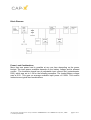
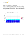
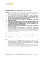
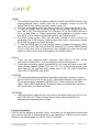
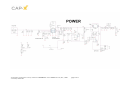
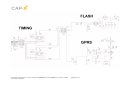
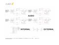
User’s Manual
Mobile Phone Power Management
Evaluation Board
APPEB1010 rev.1, Nov., 2006
All information contained herein is strictly confidential
© CAP-XX Pty Limited 2006
APPEB1010 User’s Manual rev1.0, Nov., 2006
page 1 of 11
Mobile Phone Power Management Evaluation Board
Introduction
CAP-XX supercapacitors are thin enough to fit inside a mobile phone and can supply
the phone’s peak power needs. This evaluation board allows the user to test the
CAP-XX power management architecture. Typical peak power loads that need
support are the camera phone high brightness LED flash (4x LEDS @ 1A each), the
GPRS Power Amplifier and class D audio amplifiers. Depending on the power budget
(determined by the on-board adjustable battery current limit) these loads may be
supported simultaneously. The board also has connections for other peak power
loads that the user may wish to evaluate such as hard drives etc.
Timing circuitry is included for the LED flash (67ms or 133ms) and for the GPRS
Power Amplifier simulator (25% duty cycle for class 10 and 2% for network poll
simulation). User timing can be connected however take NOTE not to exceed the
thermal limits of the high brightness LEDs. They should not be turned on for longer
than 200ms and allow a rest time of 3s.
Board Summary (7 sub-circuits)
1. POWERBuck/boost from battery to supercapacitor (3.8V or 5.2V rail).
GPRS PA regulator (3.5V), analog (3.3V), reference (1.2V).
Adjustable battery current limit upto 2A.
2. FLASH-
Four high brightness LEDs.
Adjustable current limit upto 4A.
External LEDs can be connected.
3. GPRS-
Adjustable PA current upto 2A.
External rail can be connected.
4. TIMING-
PIC microcontroller (space for second controller).
On-board or external timing for Flash and GPRS.
5. AUDIO-
4x 2.75W peak power class D audio amplifiers.
Single ended or differential input.
6. INTERNAL- DIP switch selectable continuous load simulators.
7. EXTERNAL- Can connect other high power loads.
All information contained herein is strictly confidential
© CAP-XX Pty Limited 2006
APPEB1010 User’s Manual rev1.0, Nov., 2006
page 2 of 11
Block Diagram
Power Load Combinations
More than one power load is possible at any one time depending on the power
budget. The input power available depends on the battery voltage and its allowed
current. The evaluation board has an adjustable input current limit (potentiometer
R23), which was set to 1.5A for the following examples. The loaded battery voltage
was at 3.5V. This gave an average available input power of 5.25W. This section
looks at some typical load combinations.
All information contained herein is strictly confidential
© CAP-XX Pty Limited 2006
APPEB1010 User’s Manual rev1.0, Nov., 2006
page 3 of 11
Network Poll (2% duty cycle) & LED Flash (4A @ 133ms)
This shows that the supercapacitor can provide the 4A required to drive four high
brightness LEDs whilst remain in contact with the network (another 1.8A). There is no
need to gate the Flash off during network polls eliminating the possibility of dark lines
in the photo. Sourcing these 5.8A pulses at an average of approximately 4.5V is
impossible without the use of a supercapacitor.
Network Poll & LED Flash
Voltage (V), Current (A)
7
6
5
4
Flash + PA (A)
Vout (V)
3
Battery (A)
2
1
0
-1
-0.05
0
0.05
0.1
0.15
0.2
0.25
0.3
0.35
0.4
0.45
time (s)
All information contained herein is strictly confidential
© CAP-XX Pty Limited 2006
APPEB1010 User’s Manual rev1.0, Nov., 2006
page 4 of 11
GPRS class 10 & 2W Continuous Audio (1kHz test signal)
In this particular example it can be seen that the PA can be fully supported at 33dBm
(1.8A & 3.5V) whilst still providing 2W continuous audio (2x4Ω speakers each with
500mA rms). Note that much higher peak power would be available for burst loads
(rather than continuous) such as bass (so long as the average does not exceed 2W).
There is no need to gate the audio off during class 10 transmissions.
GPRS & Continuous Audio
Voltage (V), Current (A)
5
4
3
Battery (A)
Each Speaker (A)
PA (A)
2
Vout (V)
PA (V)
1
0
-1
-0.001
0
0.001
0.002
0.003
0.004
0.005
0.006
0.007
0.008
0.009
time (s)
All information contained herein is strictly confidential
© CAP-XX Pty Limited 2006
APPEB1010 User’s Manual rev1.0, Nov., 2006
page 5 of 11
Network Poll (2% duty cycle) & 3.3W Continuous Audio
Since the average power for the PA has dropped by a factor of 12.5 (from 25% duty
cycle to 2%) more power is available for the audio. In this example the continuous
audio power is 3.3W (2x4Ω speakers each with 640mA rms). Note that much higher
peak power would be available for burst loads (rather than continuous) such as bass
(so long as the average does not exceed 3.3W). There is no need to gate the audio
off during network polls.
Network Poll & Continuous Audio
Voltage (V), Current (A)
6
5
4
Vout (V)
3
1x Speaker (A)
PA (A)
Battery (A)
2
1
0
-1
-0.01
0
0.01
0.02
0.03
0.04
0.05
0.06
0.07
0.08
0.09
time (s)
All information contained herein is strictly confidential
© CAP-XX Pty Limited 2006
APPEB1010 User’s Manual rev1.0, Nov., 2006
page 6 of 11
Circuit Description (refer to schematics at the end of this manual)
POWER
1. Connect a Li ion battery (or bench top supply) to J3 observing correct polarity
(Bat- & Bat+ marked). The Linear Technology buck/boost LTC3442 (U2) has a
maximum input voltage of 5.5V and a minimum of 2.4V.
2. The current from the battery can be limited up to 2A by adjusting the
potentiometer R23. A high current limit enables the maximum power to be
delivered to a combination of power loads. A low current limit might only enable
one power load however it maximises the battery runtime.
3. Jumpers J1 and J2 allow the inductor and supercapacitor current to be
measured respectively.
4. If the Flash or high power audio is not required then the supercapacitor voltage
(output of the buck/boost) may be set to only 3.8V (else 5.2V is required). This
is done manually using the toggle switch SW2. This Vout_select signal is also
connected to J8 if remote switching is required.
5. J4 and J5 of the EXTERNAL section provide convenient points to measure the
supercapacitor voltage.
6. Two indicating LEDs are provided to show the input voltage (Vin) and the
supercapacitor voltage (Vout). Note that the Vout LED can still be illuminated
even when the battery is removed. This is because of the energy stored in the
supercapacitor. The LEDs can be disconnected using J7 if their constant drain
on the battery is undesirable.
FLASH
1. The LEDs’ total current can be measured and adjusted by using a loop on J16
and the potentiometer R34 respectively.
2. External LEDs can be tested by connecting them to J16 and J15.
3. DO NOT use an external timing source that drives the LEDs for longer than
200ms and be sure to allow a 3s thermal recovery time.
GPRS
1. This simulates a typical GPRS Power Amplifier (PA). The onboard timing is
programmed for class 10 (25% duty cycle) or a network poll (2% duty cycle).
The current can be measured and adjusted using a loop on J9 and the
potentiometer R48 (upto 2A) respectively.
2. This board is designed for class 10 operation, if any other timings or rails are
connected be sure not to violate the thermal limits of the three power resistors
R37,R38,R39 and the MOSFET M2 (Zetex ZXM64N02X).
All information contained herein is strictly confidential
© CAP-XX Pty Limited 2006
APPEB1010 User’s Manual rev1.0, Nov., 2006
page 7 of 11
TIMING
1. The onboard timing can be used to signal the FLASH and GPRS sections. The
preprogrammed timing modes used can be manually chosen by the DIP
switch SW4 or they can be remotely chosen using J10.
2. The user can implement their own timing modes by connecting directly to J8.
3. To use the FLASH with on board timing connect jumpers across pins 5&6,
pins 7&8 of J10. This instructs the PIC controller (U7) on the FLASH options of
off or on and 67ms or 133ms respectively. Also needed is a jumper across
pins 9&10 of J8 to connect this timing signal to the FLASH section.
4. The push button switch SW3 can be used instead of pin1 of SW4 for
generating the FLASH signal. Holding down this button continuously causes
the FLASH to pulse every three seconds.
5. To use the GPRS with on board timing connect jumpers across pins 9&10,
pins 11&12 of J10. This instructs the PIC controller (U7) on the GPRS options
of 2% or 25% and off or on respectively. Also needed is a jumper across pins
13&14 of J8 to connect this timing signal to the GPRS section.
AUDIO
1. There are four separate audio channels each rated at 2.75W (Texas
Instruments TPA2032D1). They are designed to drive 4Ω speakers.
2. For single ended input signals, ground the IN+ pin using a jumper on pins 5&7
of the relevant channel jumper (J13, J14, J12, J11). Connect the ground of the
input signal to IN+ and the single ended input to IN-. For more information
refer to the TPA2032D1 data sheet.
INTERNAL
1. This simulates continuous loads by manually switching in resistors to either
the Vout rail (5.2V) or the PA rail (3.5V). Only those resistors connected to the
PA rail are presently populated (R5,R4,R3,R1). These resistors are 360Ω,
180Ω, 180Ω, 180Ω respectively. This allows various combinations (using the
DIP switch SW1) of 10mA and 20mA.
EXTERNAL
1. Other high power loads may be connected to this board using J4 & J5 for Vout
and J6 & J5 for PA. These jumpers also provide convenient points for
measuring the supercapacitor voltage.
Further Information
CAP-XX will be pleased to provide further information on the applications described
here, and on the use of supercapacitors in any application. Please use the contact
details on the header page, or visit the CAP-XX web site.
All information contained herein is strictly confidential
© CAP-XX Pty Limited 2006
APPEB1010 User’s Manual rev1.0, Nov., 2006
page 8 of 11
All information contained herein is strictly confidential
© CAP-XX Pty Limited 2006
APPEB1010 User’s Manual rev1.0, Nov., 2006
page 9 of 11
All information contained herein is strictly confidential
© CAP-XX Pty Limited 2006
APPEB1010 User’s Manual rev1.0, Nov., 2006
page 10 of 11
All information contained herein is strictly confidential
© CAP-XX Pty Limited 2006
APPEB1010 User’s Manual rev1.0, Nov., 2006
page 11 of 11