1
Owner’s Manual
Keep This Manual For Future Reference.
EN
Contents
Accessories
PRECAUTIONS................................... 5
• Owner’s Manual
• AC power cable
• Dante Virtual Soundcard license code
(Please check the package contents.)
Introduction .................................... 7
Features .............................................................7
Firmware Updates ..............................................7
Precautions for Rack Mounting ..........................7
Recessed Installation ..........................................8
About Dante .................................... 8
Controls and Functions.................... 9
Front Panel ........................................................9
Rear Panel........................................................ 12
About Connections ........................ 13
Daisy Chain Network .......................................13
Star Network.................................................... 13
About Dante Controller.................................... 14
Head Amp Control ......................... 15
Control from an Rio-native Device ................... 15
Control from a Device That Does Not
Feature Rio-Native Support .......................15
Head Amplifier Parameters That Can be
Monitored and Controlled ........................ 15
Troubleshooting ............................ 16
Troubleshooting .............................................. 16
Messages ......................................................... 17
Specifications................................. 19
General Specifications ......................................19
Analog Input Characteristics ............................20
Analog Output Characteristics ......................... 20
Digital I/O Characteristics ................................20
Digital Output Characteristics .......................... 20
Dimensions ......................................................21
2
Owner’s Manual
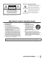
Explanation of Graphical Symbols
The lightning flash with arrowhead symbol
within an equilateral triangle is intended to alert
the user to the presence of uninsulated
“dangerous voltage” within the product’s
enclosure that may be of sufficient magnitude to
constitute a risk of electric shock to persons.
CAUTION
RISK OF ELECTRIC SHOCK
DO NOT OPEN
The exclamation point within an equilateral
triangle is intended to alert the user to the
presence of important operating and
maintenance (servicing) instructions in the
literature accompanying the product.
CAUTION: TO REDUCE THE RISK OF
ELECTRIC SHOCK, DO NOT REMOVE
COVER (OR BACK). NO USER-SERVICEABLE
PARTS INSIDE. REFER SERVICING TO
QUALIFIED SERVICE PERSONNEL.
The above warning is located on the top of the unit.
IMPORTANT SAFETY INSTRUCTIONS
1
2
3
4
5
6
7
8
9
10
Read these instructions.
Keep these instructions.
Heed all warnings.
Follow all instructions.
Do not use this apparatus near water.
Clean only with dry cloth.
Do not block any ventilation openings. Install in
accordance with the manufacturer’s instructions.
Do not install near any heat sources such as radiators,
heat registers, stoves, or other apparatus (including
amplifiers) that produce heat.
Do not defeat the safety purpose of the polarized or
grounding-type plug. A polarized plug has two blades
with one wider than the other. A grounding type plug
has two blades and a third grounding prong. The wide
blade or the third prong are provided for your safety. If
the provided plug does not fit into your outlet, consult
an electrician for replacement of the obsolete outlet.
Protect the power cord from being walked on or pinched
particularly at plugs, convenience receptacles, and the
point where they exit from the apparatus.
11
12
13
14
Only use attachments/accessories specified by the
manufacturer.
Use only with the cart, stand,
tripod, bracket, or table specified
by the manufacturer, or sold with
the apparatus. When a cart is
used, use caution when moving
the cart/apparatus combination
to avoid injury from tip-over.
Unplug this apparatus during
lightning storms or when unused for long periods of
time.
Refer all servicing to qualified service personnel.
Servicing is required when the apparatus has been
damaged in any way, such as power-supply cord or plug
is damaged, liquid has been spilled or objects have
fallen into the apparatus, the apparatus has been
exposed to rain or moisture, does not operate normally,
or has been dropped.
WARNING
TO REDUCE THE RISK OF FIRE OR ELECTRIC SHOCK, DO NOT EXPOSE THIS APPARATUS TO RAIN OR MOISTURE.
(UL60065_03)
Owner’s Manual
3
FCC INFORMATION (U.S.A.)
1. IMPORTANT NOTICE: DO NOT MODIFY THIS UNIT!
not guarantee that interference will not occur in all installations. If
this product is found to be the source of interference, which can be
determined by turning the unit “OFF” and “ON”, please try to eliminate the problem by using one of the following measures:
Relocate either this product or the device that is being affected by
the interference.
Utilize power outlets that are on different branch (circuit breaker or
fuse) circuits or install AC line filter/s.
In the case of radio or TV interference, relocate/reorient the
antenna. If the antenna lead-in is 300 ohm ribbon lead, change the
lead-in to co-axial type cable.
If these corrective measures do not produce satisfactory results,
please contact the local retailer authorized to distribute this type of
product. If you can not locate the appropriate retailer, please contact
Yamaha Corporation of America, Electronic Service Division, 6600
Orangethorpe Ave, Buena Park, CA90620
The above statements apply ONLY to those products distributed by
Yamaha Corporation of America or its subsidiaries.
This product, when installed as indicated in the instructions contained in this manual, meets FCC requirements. Modifications not
expressly approved by Yamaha may void your authority, granted by
the FCC, to use the product.
2. IMPORTANT: When connecting this product to accessories and/
or another product use only high quality shielded cables. Cable/s
supplied with this product MUST be used. Follow all installation
instructions. Failure to follow instructions could void your FCC
authorization to use this product in the USA.
3. NOTE: This product has been tested and found to comply with the
requirements listed in FCC Regulations, Part 15 for Class “B” digital
devices. Compliance with these requirements provides a reasonable level of assurance that your use of this product in a residential
environment will not result in harmful interference with other electronic devices. This equipment generates/uses radio frequencies
and, if not installed and used according to the instructions found in
the users manual, may cause interference harmful to the operation
of other electronic devices. Compliance with FCC regulations does
* This applies only to products distributed by YAMAHA CORPORATION OF AMERICA.
(class B)
COMPLIANCE INFORMATION STATEMENT
(DECLARATION OF CONFORMITY PROCEDURE)
Responsible Party :
Address :
Telephone :
Type of Equipment :
Model Name :
Yamaha Corporation of America
6600 Orangethorpe Ave., Buena Park, Calif. 90620
714-522-9011
I/O RACK
Rio3224-D/Rio1608-D
This device complies with Part 15 of the FCC Rules.
Operation is subject to the following two conditions:
1) this device may not cause harmful interference, and
2) this device must accept any interference received including interference
that may cause undesired operation.
See user manual instructions if interference to radio reception is suspected.
* This applies only to products distributed by
YAMAHA CORPORATION OF AMERICA.
(FCC DoC)
IMPORTANT NOTICE FOR THE UNITED KINGDOM
Connecting the Plug and Cord
WARNING: THIS APPARATUS MUST BE EARTHED IMPORTANT.
The wires in this mains lead are coloured in accordance with the following code:
GREEN-AND-YELLOW : EARTH
BLUE
: NEUTRAL
BROWN
: LIVE
As the colours of the wires in the mains lead of this apparatus may not
correspond with the coloured markings identifying the terminals in
your plug proceed as follows:
The wire which is coloured GREEN-and-YELLOW must be connected
to the terminal in the plug which is marked by the letter E or by the
safety earth symbol
or colored GREEN or GREEN-and-YELLOW.
The wire which is coloured BLUE must be connected to the terminal
which is marked with the letter N or coloured BLACK.
The wire which is coloured BROWN must be connected to the terminal
which is marked with the letter L or coloured RED.
(3 wires)
4
Owner’s Manual
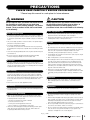
PRECAUTIONS
PLEASE READ CAREFULLY BEFORE PROCEEDING
* Please keep this manual in a safe place for future reference.
WARNING
CAUTION
Always follow the basic precautions listed below to avoid
the possibility of serious injury or even death from
electrical shock, short-circuiting, damages, fire or other
hazards. These precautions include, but are not limited
to, the following:
Always follow the basic precautions listed below to avoid
the possibility of physical injury to you or others, or
damage to the device or other property. These
precautions include, but are not limited to, the following:
Power supply/Power cord
Power supply/Power cord
• Do not place the power cord near heat sources such as heaters or radiators, and
do not excessively bend or otherwise damage the cord, place heavy objects on
it, or place it in a position where anyone could walk on, trip over, or roll anything
over it.
• Only use the voltage specified as correct for the device. The required voltage is
printed on the name plate of the device.
• Use only the supplied power cord/plug.
If you intend to use the device in an area other than in the one you purchased,
the included power cord may not be compatible. Please check with your Yamaha
dealer.
• Check the electric plug periodically and remove any dirt or dust which may have
accumulated on it.
• Be sure to connect to an appropriate outlet with a protective grounding
connection. Improper grounding can result in electrical shock.
• When removing the electric plug from the device or an outlet, always hold the
plug itself and not the cord. Pulling by the cord can damage it.
• Remove the electric plug from the outlet when the device is not to be used for
extended periods of time, or during electrical storms.
Location
• Do not place the device in an unstable position where it might accidentally fall
over.
• Do not block the vents. This device has ventilation holes at the rear to prevent
the internal temperature from becoming too high. In particular, do not place the
device on its side or upside down. Inadequate ventilation can result in
overheating, possibly causing damage to the device(s), or even fire.
• To avoid damage, do not install or store the device in a place subject to salty air
or corrosive gas or chemicals.
• Before moving the device, remove all connected cables.
Do not open
• This device contains no user-serviceable parts. Do not open the device or
attempt to disassemble the internal parts or modify them in any way. If it should
appear to be malfunctioning, discontinue use immediately and have it inspected
by qualified Yamaha service personnel.
Water warning
• Do not expose the device to rain, use it near water or in damp or wet conditions,
or place on it any containers (such as vases, bottles or glasses) containing
liquids which might spill into any openings. If any liquid such as water seeps
into the device, turn off the power immediately and unplug the power cord from
the AC outlet. Then have the device inspected by qualified Yamaha service
personnel.
• Never insert or remove an electric plug with wet hands.
Fire warning
• When setting up the device, make sure that the AC outlet you are using is easily
accessible. If some trouble or malfunction occurs, immediately turn off the
power switch and disconnect the plug from the outlet. Even when the power
switch is turned off, electricity is still flowing to the product at the minimum
level. When you are not using the product for a long time, make sure to unplug
the power cord from the wall AC outlet.
• If the device is mounted in an EIA standard rack, carefully read the section
“Precautions for Rack Mounting” on page 7. Inadequate ventilation can result in
overheating, possibly causing damage to the device(s), malfunction, or even
fire.
Connections
• Before connecting the device to other devices, turn off the power for all devices.
Before turning the power on or off for all devices, set all volume levels to
minimum.
Maintenance
• Do not put burning items, such as candles, on the unit. A burning item may fall
over and cause a fire.
• Remove the power plug from the AC outlet when cleaning the device.
Handling caution
If you notice any abnormality
• When one of the following problems occur, immediately turn off the power
switch and disconnect the electric plug from the outlet. Then have the device
inspected by Yamaha service personnel.
- The power cord or plug becomes frayed or damaged.
- It emits unusual smells or smoke.
- Some object has been dropped into the instrument.
- There is a sudden loss of sound during use of the device.
• If this device should be dropped or damaged, immediately turn off the power
switch, disconnect the electric plug from the outlet, and have the device
inspected by qualified Yamaha service personnel.
PA_en_1
• Do not insert your fingers or hands in any gaps or openings on the device
(vents, etc.).
• Avoid inserting or dropping foreign objects (paper, plastic, metal, etc.) into any
gaps or openings on the device (vents, etc.) If this happens, turn off the power
immediately and unplug the power cord from the AC outlet. Then have the
device inspected by qualified Yamaha service personnel.
• Do not rest your weight on the device or place heavy objects on it, and avoid use
excessive force on the buttons, switches or connectors.
• Do not use speakers for a long period of time at a high or uncomfortable volume
level, since this can cause permanent hearing loss. If you experience any
hearing loss or ringing in the ears, consult a physician.
1/2
Owner’s Manual
5
Information for Users on Collection and Disposal of Old
Equipment
Yamaha cannot be held responsible for damage caused by improper use or
modifications to the device, or data that is lost or destroyed.
This symbol on the products, packaging, and/or
accompanying documents means that used electrical
and electronic products should not be mixed with
general household waste.
NOTICE
For proper treatment, recovery and recycling of old
products, please take them to applicable collection
points, in accordance with your national legislation and
the Directives 2002/96/EC.
To avoid the possibility of malfunction/ damage to the
product, damage to data, or damage to other property,
follow the notices below.
Handling and Maintenance
• Do not use the device in the vicinity of a TV, radio, stereo equipment, mobile
phone, or other electric devices. Otherwise, the device, TV, or radio may
generate noise.
• Do not expose the device to excessive dust or vibrations, or extreme cold or heat
(such as in direct sunlight, near a heater, or in a car during the day) to prevent
the possibility of panel disfiguration, damage to the internal components or
unstable operation.
By disposing of these products correctly, you will help to save valuable
resources and prevent any potential negative effects on human health and the
environment which could otherwise arise from inappropriate waste handling.
For more information about collection and recycling of old products, please
contact your local municipality, your waste disposal service or the point of sale
where you purchased the items.
[For business users in the European Union]
If you wish to discard electrical and electronic equipment, please contact your
dealer or supplier for further information.
• Do not place vinyl, plastic or rubber objects on the device, since this might
discolor the panel or keyboard.
[Information on Disposal in other Countries outside the European
Union]
• When cleaning the device, use a dry and soft cloth. Do not use paint thinners,
solvents, cleaning fluids, or chemical-impregnated wiping cloths.
This symbol is only valid in the European Union. If you wish to discard these
items, please contact your local authorities or dealer and ask for the correct
method of disposal.
• Condensation can occur in the device due to rapid, drastic changes in ambient
temperature—when the device is moved from one location to another, or air
conditioning is turned on or off, for example. Using the device while
condensation is present can cause damage. If there is reason to believe that
condensation might have occurred, leave the device for several hours without
turning on the power until the condensation has completely dried out.
(weee_eu)
• The rubber feet included in this package can be attached to the bottom to prevent
slippage when it is to be used on a slippery surface.
• Always turn the power off when the device is not in use.
Connectors
• XLR-type connectors are wired as follows (IEC60268 standard): pin 1: ground,
pin 2: hot (+), and pin 3: cold (-).
Information
About copyrights
* Copying of the commercially available musical data including but not limited to
MIDI data and/or audio data is strictly prohibited except for your personal use.
About this manual
* The illustrations and LCD screens as shown in this manual are for instructional
purposes only, and may appear somewhat different from those on your device.
* The company names and product names in this manual are the trademarks or
registered trademarks of their respective companies.
European Models
Inrush Current based on EN 55103-1:2009
4A (on initial switch-on)
3A (after a supply interruption of 5s)
Conforms to Environments: E1, E2, E3 and E4
PA_en_1
6
Owner’s Manual
2/2
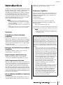
Introduction
Introduction
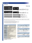
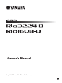
Thank you for choosing the Yamaha Rio3224-D/Rio1608-D
I/O Rack. The Rio3224-D is a Dante-compatible I/O rack,
featuring 32 analog inputs, 16 analog outputs, and 8
AES/EBU outputs. The Rio1608-D is a Dante-compatible
I/O rack, featuring16 analog inputs and 8 analog outputs.
To take full advantage of the superior functions and
performance offered by the Rio3224-D/Rio1608-D, and to
extend the useful life of the product, be sure to read this
owner’s manual carefully before operation.
NOTE
• Where specifications for the Rio3224-D differ from the
Rio1608-D, this manual places specifications that apply
only to the Rio1608-D in curly brackets { } (e.g., [INPUT]
connectors 1-32 {1-16}).
• Unless otherwise noted, illustrations for the Rio3224-D are
used.
• If certain specifications are common to both the Rio3224-D
and Rio1608-D, both units are collectively called “Rio.”
enables you to directly input or output audio signals
without using an audio interface device.
Firmware Updates
This product enables you to update the unit firmware to
improve operations, add functions, and correct possible
malfunctions. The following two types of firmware are
available for the unit.
• Unit’s firmware
• Dante module firmware
You must update each type of firmware separately.
Details on updating the firmware are available on the
following website:
http://www.yamahaproaudio.com/
For information on updating and setting up the unit, please
refer to the firmware update guide available on the website.
NOTE
Features
Long-distance Dante Network
Capability
Low-latency, low-jitter audio can be transferred over
distances up to 100 meters* between devices via standard
Ethernet cables using the Dante network protocol. The Rio
can be used as a general-purpose I/O box for the Dante
network. Supported sampling rates are 44.1 kHz, 48 kHz,
88.2 kHz, and 96 kHz.
* Maximum practical distance may vary according to the cable used.
Remotely Controllable Internal Head
Amplifiers
Internal head amplifier parameters can be remotely
controlled from a compatible device.
Digital Outputs (Rio3224-D only)
The Rio3224-D features XLR-3-32 type balanced
connectors for AES/EBU format digital audio outputs.
Gain Compensation Function
If the Rio’s Gain Compensation function is enabled from a
supported device that lets you set gain compensation (such
as CL series products), the subsequent fluctuations in
analog gain will be compensated for by internal digital
gain. The audio signal will be output to a Dante network
with a gain level that was fixed immediately before the Gain
Compensation function was enabled. In this way, you can
set the gain individually for FOH and MONITOR even if
they share the same channel.
Direct Audio In/Out With a Connected
Computer
When you update Dante firmware on the unit, be sure to
update Dante firmware on other Dante-compatible devices
connected to the Rio.
Precautions for Rack Mounting
This unit is rated for operation at ambient temperatures
ranging from 0 to 40 degrees Celsius. When mounting
the unit with other Rio unit(s) or other device(s) in an
EIA standard equipment rack, internal temperatures can
exceed the specified upper limit, resulting in impaired
performance or failure. When rack mounting the unit,
always observe the following requirements to avoid heat
buildup:
• If three or more Rio units are mounted without
space in the same rack, set the fan speeds to HIGH.
• If multiple units are mounted in the same rack with
their fan speeds set to LOW, leave a 1U rack space
between every two units. Also either leave the open
spaces uncovered or install appropriate ventilating
panels to minimize the possibility of heat buildup.
• When mounting the unit in a rack with devices such
as power amplifiers that generate a significant
amount of heat, leave more than 1U of space
between the Rio and other equipment. Also either
leave the open spaces uncovered or install
appropriate ventilating panels to minimize the
possibility of heat buildup.
• To ensure sufficient airflow, leave the rear of the rack
open and position it at least 10 centimeters from
walls or other surfaces. If the rear of the rack can’t be
left open, install a commercially available fan or
similar ventilating option to secure sufficient
airflow. If you’ve installed a fan kit, there may be
cases in which closing the rear of the rack will
produce a greater cooling effect. Refer to the rack
and/or fan unit manual for details.
Connecting the Rio with a standard Ethernet cable to a
computer that has a Dante Virtual Soundcard installed
Owner’s Manual
7
About Dante
About Dante
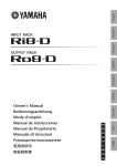
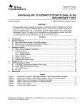
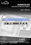
Recessed Installation
D
23
7 89 A
BC
456
If you want to recess the front panel surface of the device
from the front edge of the rack, you can adjust the position
of the rack mount brackets to recess the device by 50mm or
100mm, as shown in the illustration below.
EF 01
50 mm
100 mm
NOTE
When you install the brackets, use the same screws that
you just removed.
This product features Dante technology as a protocol to
transmit audio signals. Dante is a network protocol
developed by Audinate. It is designed to deliver
multi-channel audio signals at various sampling and bit
rates, as well as device control signals over a Giga-bit
Ethernet (GbE) network. Dante also offers the following
benefits:
• It transmits up to 512 in/512 out, for a total 1024
channels (in theory) of audio over a GbE network.
(The Rio3224-D features 32 in/24 out with a 24/32-bit
resolution. The Rio1608-D features 16 in/8 out with a
24/32-bit resolution.)
• Dante-enabled devices will automatically configure their
network interfaces and find each other on the network.
You can label Dante devices and their audio channels
with names that make sense to you.
• Dante uses high accuracy network synchronization
standards to achieve sample-accurate playback with
extremely low latency and jitter. Four types of latency are
available on the Rio: 0.25 msec, 0.5 msec, 1.0 msec, and
5.0 msec.
• Dante supports redundant connections via primary and
secondary networks to defend against unforeseen
difficulties.
• Connecting a computer to Dante network over Ethernet
enables you to directly input or output audio signals
without using any audio interface devices.
By taking advantages of these benefits, you can skip any
complicated procedures to automate connections and
setups of Dante-enabled devices, remotely control I/O
racks or amplifiers from a mixing console, or make
multi-track recordings to a DAW, such as Nuendo, installed
on a computer in the network.
Visit Audinate website for more details on Dante.
http://www.audinate.com/
More information on Dante is also posted on the Yamaha
Pro Audio website:
http://www.yamahaproaudio.com/
NOTE
Please do not use the EEE function (*) of network switches in
a Dante network.
Although power management should be negotiated
automatically in switches that support EEE, some switches do
not perform the negotiation properly. This may cause EEE to
be enabled in Dante networks when it is not appropriate,
resulting in poor synchronization performance and occasional
dropouts.
Therefore we strongly recommend that:
• If you use managed switches, ensure that they allow EEE to
be disabled. Make sure that EEE is disabled on all ports used
for real-time Dante traffic.
• If you use unmanaged switches, make sure to not use
network switches that support the EEE function, since EEE
operation cannot be disabled in these switches.
* EEE (Energy Efficient Ethernet) is a technology that reduces switch
power consumption during periods of low network traffic. It is also
known as Green Ethernet and IEEE802.3az.
8
Owner’s Manual
Controls and Functions
Controls and Functions
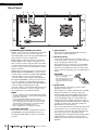
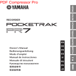
Front Panel
3
4
5 6
78 9 0 A
789A
BCD
3456
2
EF
1
012
B
C
1 [INPUT] Connectors 1–32 {1–16}
These are the XLR-3-31 type analog balanced
connectors for the input channels. The input level
range is from –62 dBu to +10 dBu. +48V phantom
power can be supplied to devices that require it via the
input connectors.
NOTE
The PAD will be switched on or off internally when the gain
of the internal head amp is adjusted between +17 dB and
+18 dB. Keep in mind that noise may be generated if there
is a difference between the Hot and Cold impedance of the
external device connected to the INPUT connector when
using phantom power.
2 [+48V] Indicators
These indicators light when +48V phantom power is
turned ON for the corresponding input channels.
Phantom power supply switching can be carried out
from a compatible digital mixing console or computer
application. No phantom power will be supplied,
however, if the [+48V MASTER] switch is OFF, even
if phantom power to individual channels is turned ON
(the +48V indicators will still light). The +48V
indicators also function as error indicators: the
indicators for all channels will flash if an error occurs.
CAUTION:
• Make sure that phantom power is turned OFF unless it is
needed.
• When turning phantom power ON, make sure that no
equipment other than phantom-powered devices such as
condenser microphones are connected to the
corresponding [INPUT] connectors. Applying phantom
power to a device that does not require phantom power can
damage the connected device.
• Do not connect or disconnect a device to an INPUT while
phantom power is applied. Doing so can damage the
connected device and/or the unit itself.
• To prevent possible damage to speakers, make sure that
power amplifiers and/or powered speakers are turned OFF
when switching phantom power ON or OFF. We also
recommend setting all digital mixing console output
controls to minimum when turning phantom power ON or
OFF. Sudden high level peaks caused by the switching
operation can damage equipment as well as the hearing of
those present.
3 [SIG] (Signal) Indicators
These indicators light green when the signal applied
to the corresponding channel reaches or exceeds
–34 dBFS.
The SIG indicators also function as error indicators:
the indicators for all channels will flash if an error
occurs.
4 [PEAK] Indicators
These indicators light red when the signal level of the
corresponding channel reaches or exceeds –3 dBFS.
The PEAK indicators also function as error
indicators: the indicators for all channels will flash if
an error occurs.
5 [UNIT ID] Rotary Switch
This rotary switch enables you to set an ID number so
that connected devices will recognize the Rio. The
UNIT ID must be a unique number in the network so
that the Rio will be able to transmit and receive audio
signals over a Dante network, or be controlled from a
connected digital mixing console.
Use the rotary switch while the power to the unit is
turned OFF. Otherwise, the ID setting will not be
effective.
Owner’s Manual
9
Controls and Functions
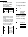
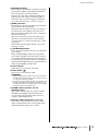
6 DIP Switches
These switches enable you to specify the settings
related to the startup operation of the unit.
Set the DIP switches while the power to the unit is
turned OFF. Otherwise, the setting will not be
effective.
Refer to the following for details.
• Switch 1 (UNIT ID)
This switch setting determines whether the
hexadecimal setting of the [UNIT ID] rotary switch
will range from 0 to F or from 10 to 1F.
Switch
1
1
Setting
Description
UNIT ID
ranging from
0 to F
The setting range of the
[UNIT ID] rotary switch is
from 0 to F.
UNIT ID
ranging from
10 to 1F
The setting range of the
[UNIT ID] rotary switch is
from 10 to 1F.
• Switch 4 (SECONDARY PORT)
This switch setting determines whether the rear-panel
[SECONDARY] connector will be used for a daisy
chain or redundant network.
With the [DAISY CHAIN] setting, you can connect
multiple Dante-enabled network devices in a daisy
chain without using a network switch. Refer to “Daisy
Chain Network” in the “About Connections” section
(see page 13) for more information about daisy chain
connections.
With the [REDUNDANT] setting, the [PRIMARY]
connector will be used for primary connections, and
the [SECONDARY] connector will be used for
secondary (backup) connections. If the unit is unable
to transmit signals through the [PRIMARY]
connector for some reason (e.g., due to damage or
accidental removal of the cable, or a failed network
switch), the [SECONDARY] connector will
automatically take over communications and
functions on the redundant network. Refer to “About
Redundant Networks” in the “About Connections”
section (see page 13) for more information on
redundant networks.
Switch
Setting
DAISY CHAIN
4
REDUNDANT
4
10
• Switches 5 and 6 (REMOTE)
When you plan to monitor or control the Rio from a
digital mixing console, these switches determine
whether to use an Rio-native device (such as a CL
series product) or a non-Rio-native device.
Information on which devices feature Rio-native
support is available at the Yamaha pro audio website
product page:
http://www.yamahaproaudio.com/products/
Switch
Setting
NATIVE
An Rio-native device will control
the Rio.
AD8HR
A non-Rio-native device will
control the Rio as AD8HRs.
In this case, Rio3224-D and
Rio1608-D are recognized as
four AD8HRs and two AD8HRs
respectively.
Set the UNIT ID number
between 1 and F. The unit with
any other UNIT ID numbers will
not be controllable.
5 6
5 6
• Switches 7 and 8 (START UP MODE)
These switches determine whether part of the internal
memory is initialized when the unit starts up, or uses
the previous settings (i.e., settings used prior to the
most recent power-off).
If you plan to connect an Rio-native device, such as a
CL series product, set the switches to [REFRESH].
The Rio will not input or output audio until the
connected Rio-native device transmits its settings to
the Rio, so that the Rio will not output audio
accidentally.
Switch
Setting
REFRESH
7 8
Description
The [SECONDARY]
connector is used for a
daisy chain connection. A
signal at the [PRIMARY]
connector will be
transmitted to the next
device in the chain as is.
The [SECONDARY]
connector is used for a
redundant network. It will
function as backup
connection, independent of
the network to which the
[PRIMARY] connector is
connected.
Owner’s Manual
Description
RESUME
7 8
Description
The Rio starts up with part of
the internal memory initialized.
The following settings are
initialized.
HA GAIN
–6 dB
+48V
OFF
HPF
OFF
HPF
80Hz
Gain Compensation
OFF
Dante Patch
OFF
The unit starts up using the
settings assigned prior to the
most recent power-off.
Controls and Functions
7 [SYSTEM] Indicators
These indicators show the Rio’s operating status. If the
green indicator lights steadily and the red indicator
turns off, the unit is operating normally.
When power to the unit is turned ON, if the green
indicator turns off, or if the red indicator lights or
flashes, the unit is not functioning properly. In this
case, refer to the “Messages” section (see page 17).
8 [SYNC] Indicators
These indicators show the operating status of the Rio’s
internal Dante network capability.
If the green indicator lights, the unit is operating as a
word clock slave and synching to the word clock.
If the green indicator flashes, the unit is operating as
the word clock master.
If the power to the unit is turned on but the green
indicator is turned off, the unit is not functioning
properly. In this case, refer to the “Messages” section
(see page 17).
If the orange indicator lights or flashes, refer to the
“Messages” section.
9 [+48V MASTER] Switch
This is the master switch for the unit’s +48V phantom
power supply.
If the [+48V MASTER] switch is off, no phantom
power will be supplied to the unit’s input connectors
even if the individual input phantom power settings
are ON. However, the [+48V] indicators will light on
channels for which phantom power is turned ON even
if the [+48V MASTER] switch is OFF.
0 Power Indicator
Lights when AC power to the unit is ON.
A Power Switch (
)
Turns power to the unit ON or OFF.
CAUTIONS:
• Rapidly turning the unit on and off in succession can cause
it to malfunction. After turning the unit off, wait for about 6
seconds before turning it on again.
• Even when the power switch is turned off, electricity is still
flowing to the product at the minimum level. When you are
not using the product for a long time, make sure to unplug
the power cord from the wall AC outlet.
B AES/EBU OUT Connectors 1/2–7/8
(Rio3224-D only)
These XLR-3-32 type balanced connectors deliver
AES/EBU format digital output from the unit’s
corresponding output channels. Each connector
outputs 2-channel digital audio.
C OUTPUT +4 dBu Connectors 1–16 {1–8}
These XLR-3-32 type balanced connectors deliver
analog output from the unit’s corresponding output
channels. Nominal output level is +4 dBu.
Owner’s Manual
11
Controls and Functions
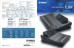
Rear Panel
D
E
F
D [PRIMARY]/[SECONDARY] Connectors
The Rio can be connected to other Dante-compatible
devices (such as a CL-series product) via these
etherCON (RJ45) connectors using standard Ethernet
cables (CAT5e or better recommended).
If DIP switch 4 on the front panel is set upward (to
DAISY CHAIN), audio signals coming into one of
these connectors will be output from the other. Refer
to “Daisy Chain Network” in the “About Connections”
section (see page 13) for more information on daisy
chain connections.
If DIP switch 4 on the front panel is set downward (to
REDUNDANT), the [PRIMARY] connector will be
used for primary connection, and the [SECONDARY]
connector will be used for secondary (backup)
connection. If the unit is unable to transmit signals
through the [PRIMARY] connector for some reason
(e.g., due to damage or accidental removal of the
cable, or a failed network switch), the [SECONDARY]
connector will automatically take over the
connection. Refer to “About Redundant Networks” in
the “About Connections” section (see page 13) for
more information on redundant networks.
NOTE
• The use of Ethernet cables with Neutrik EtherCon CAT5e
compatible RJ-45 plugs is recommended. Standard RJ45
plugs can also be used.
• Use STP (shielded twisted pair) cable to prevent
electromagnetic interference. Make sure that the metal
parts of the plugs are electrically connected to the STP
cable shield by conductive tape or comparable means.
• Connect only Dante-compatible devices or
GbE-compatible devices (including a computer).
E [LINK/ACT] Indicators
These indicators show the communication status of
the [PRIMARY] and [SECONDARY] connectors.
They flash fast if the Ethernet cables are connected
properly.
12
H
G
Owner’s Manual
F [1G] Indicators
These indicators light when the Dante network is
functioning as Giga-bit Ethernet.
G AC IN Connector
Connect the supplied AC power cord here. First,
connect the power cord to the device, then insert the
power cord plug into the AC outlet.
The supplied power cord features a special latching
mechanism (V-LOCK) to prevent the power cord
from being accidentally disconnected. Connect the
power cord by inserting the power cord fully until it is
locked.
CAUTION:
Be sure to turn the power off
before connecting or
disconnecting the power cord.
Press the latch button on the
plug to disconnect the power
cord.
H [FAN] Switch
Sets the internal cooling fan to operate at either
[HIGH] or [LOW] speed.
This switch is set to [LOW] when the unit is initially
shipped from the factory. As long as the unit is
operated within the specified ambient temperature
range either the [LOW] or [HIGH] setting can be
used. The [HIGH] setting is recommended if the
ambient temperature is high, if the unit is in direct
sunlight even if the ambient temperature is within the
specified operating range, and in any situation in
which fan noise is not a problem.
If two or more Rio units are mounted in the same rack
and the fan speed is set to [LOW], leave a 1U rack
space between every two units. Also either leave the
open spaces uncovered or install appropriate
ventilating panels to minimize the possibility of heat
buildup. If three or more Rio units are mounted
without space in the same rack, set the fan speeds to
[HIGH].
About Connections
About Connections
There are two ways to connect the Rio to a Dante network.
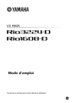
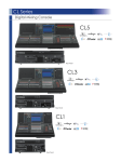
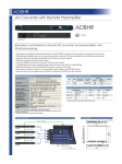
Daisy Chain Network
A daisy chain is a wiring scheme in which multiple devices
are connected together in sequence. In this way,
networking is simple and requires no network switches.
This connection method is suitable for a simple system
with a small number of devices.
However, if a large number of devices are connected, the
latency value must be increased. Also, if a connection is
broken in a daisy chain network, the signal flow is
interrupted at that point and no signal will be transferred
beyond that point.
CL5
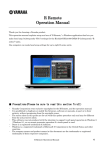
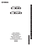
Star Network
In a star network, each device is connected to a central
network switch. Using a GbE-compatible network switch
enables you to configure a wide-band, large-scale network.
We recommend a network switch that features various
functions to control and monitor the network (such as Qos,
the ability to assign priority to data flows - e.g., clock
synchronization or audio transmission on certain data
circuits.)
With this topology, it is common to configure a redundant
network so that an unexpected network problem will not
affect any audio or otherwise stable communications.
About Redundant Networks
A redundant network consists of two circuits, a primary
circuit and a secondary circuit. Normally, the network
operates on the primary circuit. However, if the primary
connection is broken, the secondary circuit will
automatically take over communications. Therefore, using
a redundant network with a star topology would increase
communication stability relative to a daisy chain network.
Computer
CL5
789A
Network switch B
012
23
BC D
45 6
Rio3224-D (ID#1)
34
EF
34
Network switch A
23
01
ON
1 2 3 4 5 6 7 8
EF
EF
SECONDARY
EF
PRIMARY
789A
BC D
45 6
Rio3224-D (ID#1)
01
012
EF
23
789A
BC D
45 6
Rio3224-D (ID#2)
01
PRIMARY
34
012
Primary Dante
Secondary Dante
ON
ON
1 2 3 4 5 6 7 8
EF
01
EF
34
EF
23
789A
BC D
45 6
Rio3224-D (ID#2)
1 2 3 4 5 6 7 8
Owner’s Manual
13
012
About Connections
About Dante Controller
Dante Controller is a software application that allows
configuration and audio routing of Dante networks. Use
this application if you plan to connect or set up
Dante-enabled devices that do not feature Rio-native
support. Please download the Dante Controller application
from the website listed below.
Please note that Dante Controller Version 3.2.1 or later
supports Rio.
http://www.yamahaproaudio.com/
To run Dante Controller, a computer must feature a
GbE-compatible Ethernet connector.
Refer to the Dante Controller owner’s manual for details on
Dante Controller.
In Dante Controller, make the following basic settings:
• [Network View] → [Routing] → I/O patching
• [Network View] → [Clock Status] → Word clock master
setting
• [Device View] → [Config] → Sampling rate setting
14
Owner’s Manual
Head Amp Control
Head Amp Control
The Rio head amplifiers can be remotely controlled from a
host device, such as a compatible Yamaha digital mixing
console.
Control from an Rio-native
Device
The Rio head amplifiers can be controlled remotely from
an Rio-native digital mixing console, such as a CL series
product.
The connected Rio-native device displays the model name
and UNIT ID number of the corresponding Rio unit to be
controlled.
If you plan to connect a device that features Rio native
support to monitor and control the head amplifiers, refer to
the owner’s manual for the corresponding device.
Control from a Device That
Does Not Feature Rio-Native
Support
This section explains how to configure the Rio settings that
are required to control the Rio as AD8HR units from a
device that does not feature Rio-native support.
Setting the UNIT ID
The Rio3224-D will be assigned four virtual IDs (as
AD8HR Device IDs) if the DIP switches are set to
[AD8HR]. The Rio1608-D will be assigned two virtual IDs
if the DIP switches are set to [AD8HR].
If you combine Rio3224-D and Rio1608-D or add an
AD8HR or SB168-ES in the network, make sure that the
virtual IDs or Device IDs are all unique. The Rio UNIT IDs
and virtual IDs are organized as follows:
UNIT ID
(Hexadecimal)
Virtual ID (Hexadecimal)
Rio3224-D
Rio1608-D
1
1, 2, 3 ,4
1, 2
2
5, 6, 7, 8
3, 4
3
9, A, B, C
5, 6
4
D, E, F, 10
7, 8
Set the Rio correctly so that you can control it as AD8HRs.
In addition, scene recall can be used to recall all head
amplifier settings at once. Refer to the digital mixing
console owner’s manual for details on head amplifier
control.
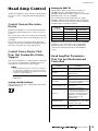
Head Amplifier Parameters
That Can be Monitored and
Controlled
Parameter
NOTE
Description
The following Yamaha non-Rio-native devices enable you
to control the Rio as AD8HRs. To connect such a device,
first install a Dante-MY16-AUD card (firmware version 3.3.8
or later) into the Mini-YGDAI slot.
+48V
Turns +48V phantom power ON or
OFF for each channel.
HA GAIN
Adjusts gain from –6 dB to 66 dB in
1-dB increments.
M7CL, LS9, DM1000, DM2000, PM5D/DSP5D,
DME64N/24N
HPF
Turns the high-pass filter ON or
OFF.
Setting the DIP Switches
HPF FREQ
Adjusts the cutoff frequency of the
high-pass filter (12 dB/Oct.) from 20
Hz to 600 Hz in 60 steps.
While the power to the unit is off, flip DIP switch 5 down
and DIP switch 6 up.
METER
(Rio-native device only)
Displays a level meter for each
input channel.
Device ID
Displays the automatically
assigned Device ID numbers 1–3C
(corresponding to AD8HR device
ID numbers). Four ID numbers are
assigned to each Rio3224-D unit
and two numbers to each
Rio1608-D unit.
+48V Master SW
Displays the [+48V MASTER]
switch ON/OFF status of the +48V
phantom power supply.
Gain Compensation
(Rio-native device only)
Turns the Gain Compensation ON
or OFF.
5 6
Owner’s Manual
15
Troubleshooting
Troubleshooting
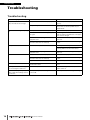
Troubleshooting
Symptom
The power won’t turn on.
The power indicator doesn’t light.
The unit is not receiving an input signal.
The input level is too low.
Cause
Possible Solution
The power cable is connected improperly.
Connect the power cable properly (see
page 12).
The [POWER] switch is not turned ON.
Turn the [POWER] switch ON. If the power still
will not come on, refer the problem to your
Yamaha dealer.
The input cables are not connected properly.
Connect the cables properly.
The source device is not delivering an appropriate signal.
Output a signal from the source device and
make sure that the SIG indicators on the appropriate channels will light.
The internal head amplifier gain is not set to an
appropriate level.
Set the internal head amplifier gain to an appropriate level.
The DIP switches are set to REFRESH, but the
Rio-native device has not started up.
Start the Rio-native device to send the setting to
the Rio.
A condenser microphone is connected.
Turn the [+48V MASTER] switch ON.
Turn phantom power for the corresponding
channel(s) ON from the Rio-native device.
The internal head amplifier gain is not set to an
appropriate level.
Set the internal head amplifier gain to an appropriate level.
The cables are not connected properly.
Connect the cables properly.
The DIP switches are set to REFRESH, but the
Rio-native device has not started up.
Start the Rio-native device to send the setting to
the Rio.
Output is muted.
Unmute the output on the Rio-native device.
The head amp cannot be controlled.
The Rio has not been mounted on the RACK of
the Rio-native device.
Mount the Rio on the RACK of the Rio-native
device.
Adjusting the internal head amp gain
does not change the audio level.
The Gain Compensation function is turned on.
If you are not using the Gain Compensation
function, turn it off.
Adjustment of the [UNIT ID] rotary
switch or DIP switch settings seems to
be ineffective.
You may have adjusted the setting while the
power is ON.
Turn the power OFF, then change the setting.
No sound is heard.
16
Owner’s Manual
Troubleshooting
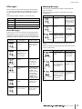
Messages
Warning Messages
Errors, warnings, and certain other types of information
are displayed via the Rio front panel indicators. Messages
are also displayed in the Dante Controller Error Status
field.
Each indicator lights or flashes as described below:
No call-out
The indicator is off.
Light
The indicator remains lit steadily.
Flash
The indicator continues to flash.
Flash x2
The indicator flashes twice cyclically.
Flash x3
The indicator flashes three times cyclically.
The indicators will light and/or flash as shown until the
cause is resolved.
If the green [SYNC] indicator is unlit, the unit’s clock is
unconfirmed.
SYNC Indicators
An internal error has
occurred.
The device has
failed. Contact your
Yamaha dealer for
repair.
Light
Flash x2
The internal memory has been corrupted.
Light
Flash x3
UNIT ID is not
unique.
Make sure that the
Ethernet cables are
not removed or
short-circuited.
Other Dante-compatible devices cannot be
found due to an incorrectly-wired Dante Network.
Make sure that the
Ethernet cables are
connected correctly.
If the green indicator is flashing, the unit is the clock
master.
If the green indicator is lit, the unit is the clock slave and the
clock is synchronized.
SYNC Indicators
The MAC address
setting has been corrupted and no communication can
occur via Dante.
The cooling fan has
stopped.
Flash x3
Possible Solution
Flash x2
Flash x3
Dante Network circuit
is broken.
Flash x2
When an error occurs, the indicators for all channels will
flash until the error is resolved, and the SYSTEM indicators
will light and/or flash cyclically as shown in the chart below.
In that case, repair is required. Contact your Yamaha dealer.
Description
Possible Solution
Set the clock master and sampling
frequency correctly
on the Rio-native
device or in Dante
Controller.
Flash
Error Messages
SYSTEM
Indicators
Description
The word clock is not
set correctly.
Check that nothing is
caught in the fan. If
the problem persists, consult your
Yamaha dealer.
Use the front-panel
DIP switches to set
START UP MODE to
REFRESH, then
restart the unit. If the
problem persists
after setting START
UP MODE back to
RESUME, consult
your Yamaha dealer.
Set a unique UNIT
ID number for the
Dante network.
Light
or
flash
Light
or
flash
Light
or
flash
Description
Possible Solution
A non-GbE-compatible device is connected.
When transferring
audio via Dante,
use device that
supports GbE.
The SECONDARY
connector has taken
over communications
during redundant network operation.
Check the circuit
connected to the
PRIMARY connector.
An abnormality has
occurred on the circuit
connected to the SECONDARY connector
during redundant network operation.
Check the circuit
connected to the
SECONDARY connector.
Light
Flash
Flash x2
Light
The DIP switches are Check the DIP switch
not set correctly.
settings, and set
them correctly.
Flash
Owner’s Manual
17
Troubleshooting
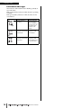
Information Messages
The indicators will remain lit and/or flashing cyclically to
report the status.
If the orange [SYNC] indicator is unlit, the unit is operating
normally.
If the green [SYNC] indicator is unlit, the unit’s clock is
unconfirmed.
SYNC Indicators
Description
Explanation
Synchronization is
occurring.
Please wait until
the unit synchronizes completely. It
may take up to 45
seconds to synchronize completely.
The unit is functioning
correctly as the word
clock master.
The unit is operating as the word
clock master.
The unit is functioning
correctly as the word
clock slave.
The unit is operating as the clock
slave and the clock
is synchronized.
Light
Flash
Light
18
Owner’s Manual
Specifications
Specifications
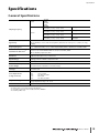
General Specifications
44.1kHz
48kHz
88.2kHz
96kHz
Internal
Sampling Frequency
External
44.1kHz
+4.1667%, +0.1%, –0.1%, –4.0%
±200ppm
48kHz
+4.1667%, +0.1%, –0.1%, –4.0%
±200ppm
88.2kHz
+4.1667%, +0.1%, –0.1%, –4.0%
±200ppm
96kHz
+4.1667%, +0.1%, –0.1%, –4.0%
±200ppm
Signal Delay
Less than 3ms
INPUT to OUTPUT, connect with CL5 using Dante, Dante Receive Latency set to 0.25ms (one way),
Fs=48kHz
Frequency Response
+0.5, –1.5dB 20Hz-20kHz, refer to +4dBu output @1kHz, INPUT to OUTPUT, Fs= 44.1kHz, 48kHz
+0.5, –1.5dB 20Hz-40kHz, refer to +4dBu output @1kHz, INPUT to OUTPUT, Fs= 88.2kHz, 96kHz
Total Harmonic Distortion*1
Less than 0.05% 20Hz-20kHz@+4dBu into 600Ω, Fs= 44.1kHz, 48kHz
Less than 0.05% 20Hz-40kHz@+4dBu into 600Ω, Fs= 88.2kHz, 96kHz
INPUT to OUTPUT, Input Gain= Min.
Hum&Noise*2
–128dBu typ., Equivalent Input Noise, Input Gain= Max.
–88dBu Residual output noise, ST master off.
Dynamic Range
112dB typ., DA Converter,
108dB typ., INPUT to OUTPUT, Input Gain= Min.
Crosstalk@1kHz
–100dB*3, adjacent INPUT/OUTPUT channels, Input Gain= Min.
Dimensions (WxHxD)
and Net Weight
Rio3224-D: 480mm x 232mm*4 x 361.5mm, 12.4kg
Power Requirements
(wattage)
Rio3224-D: 120W
Rio1608-D: 70W
Power Requirements
(voltage and hertz)
US/Canada:
Japan:
China:
Korea:
Other:
Temperature Range
Operating temperature range: 0 - 40°C
Storage temperature range: –20 - 60°C
Included Accessories
Owner’s Manual, Power Cord
Rio1608-D: 480mm x 144mm*4 x 361.5mm, 8.8kg
120V 60Hz
100V 50/60Hz
110-240V 50/60Hz
220V 60Hz
110-240V 50/60Hz
*1. Total Harmonic Distortion is measured with 18dB/octave filter @80kHz
*2. Hum & Noise are measured with A-Weight filter.
*3. Crosstalk is measured with a 30dB/octave filter @22kHz
*4. Including rubber feet.
Owner’s Manual
19
Specifications
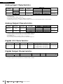
Analog Input Characteristics
Input
Terminals
GAIN
+66dB
INPUT 1-16
–6dB
+66dB
INPUT 17-32*2
–6dB
Actual Load
Impedance
For Use With
Nominal
7.5kΩ
7.5kΩ
Input Level
Nominal
Max. before clip
50-600Ω Mics &
600Ω Lines
–62dBu (0.616mV)
–42dBu (6.16mV)
+10dBu (2.45V)
+30dBu (24.5V)
50-600Ω Mics &
600Ω Lines
–62dBu (0.616mV)
–42dBu (6.16mV)
+10dBu (2.45V)
+30dBu (24.5V)
Connector
XLR-3-31 type
(Balanced)*1
XLR-3-31 type
(Balanced)*1
*1. XLR-3-31 type connectors are balanced.(1=GND, 2=HOT, 3=COLD)
*2. Rio3224-D only
* In these specifications, 0dBu = 0.775 Vrms.
* All input AD converters are 24bit linear, 128times oversampling.
* +48V DC ( phantom power ) is supplied to INPUT XLR type connectors via each individual software controlled switch.
Analog Output Characteristics
Output
Terminals
Actual Source
Impedance
For Use With
Nominal
OUTPUT 1-8
75Ω
600Ω Lines
OUTPUT 9-16*3
75Ω
600Ω Lines
Output Level
Max.Output Level
Select
SW*1
Nominal
Max. before clip
Connector
+24dB (default)
+4dBu (1.23 V)
+24dBu (12.3V)
XLR-3-32 type
+18dB
–2dBu (616mV)
+18dBu (6.16V)
(Balanced)*2
+24dB (default)
+4dBu (1.23 V)
+24dBu (12.3V)
XLR-3-32 type
+18dB
–2dBu (616mV)
+18dBu (6.16V)
(Balanced)*2
*1. There are switches inside the body to preset the maximum output level.
*2. XLR-3-32 type connectors are balanced. ( 1=GND, 2=HOT, 3=COLD )
*3. Rio3224-D only
* All output DA converters are 24bit, 128times oversampling.
* There are switches inside the body to preset the maximum output level.
Digital I/O Characteristics
Terminals
Format
Primary/Secondary
Dante
Data length
24bit or 32bit
Level
Audio
Connector
32ch (Rio3224-D to other devices)
24ch (Other devices to Rio3224-D)
1000Base-T
16ch (Rio1608-D to other devices)
8ch (Other devices to Rio1608-D)
EtherCON Cat5e
Digital Output Characteristics
Terminal
*1
AES/EBU OUT 1-4
Format
AES/EBU
Data Length
Level
24bit
RS422
*1
AES/EBU Professional use
*1. Rio3224-D only
*2. XLR-3-32 type connectors are balanced. (1= GND, 2= HOT, 3= COLD)
20
Owner’s Manual
Connector
XLR-3-32 type (Balanced)*2
Specifications
Dimensions
5.8
350
361.5
(5.7)
Rio3224-D
12
232
220
480
5.8
350
361.5
(5.7)
Rio1608-D
12
144
132
480
Unit: mm
* Specifications and descriptions in this owner’s manual are for information purposes only. Yamaha Corp. reserves the right to change or modify products or
specifications at any time without prior notice. Since specifications, equipment or options may not be the same in every locale, please check with your Yamaha
dealer.
Owner’s Manual
21
For details of products, please contact your nearest Yamaha
representative or the authorized distributor listed below.
Pour plus de détails sur les produits, veuillez-vous adresser à Yamaha ou
au distributeur le plus proche de vous figurant dans la liste suivante.
NORTH AMERICA
CANADA
Yamaha Canada Music Ltd.
135 Milner Avenue, Scarborough, Ontario,
M1S 3R1, Canada
Tel: 416-298-1311
U.S.A.
Yamaha Corporation of America
6600 Orangethorpe Ave., Buena Park, Calif. 90620,
U.S.A.
Tel: 714-522-9011
CENTRAL & SOUTH AMERICA
MEXICO
Yamaha De México, S.A. de C.V.
Av. Insurgentes Sur 1647 “Prisma Insurgentes”,
Col. San José Insurgentes, Del. Benito Juárez,
03900, México, D.F.
Tel: 55-5804-0600
BRAZIL
Yamaha Musical do Brasil Ltda.
Rua Joaquim Floriano, 913 - 4' andar, Itaim Bibi,
CEP 04534-013 Sao Paulo, SP. BRAZIL
Tel: 011-3704-1377
ARGENTINA
Yamaha Music Latin America, S.A.
Sucursal de Argentina
Olga Cossettini 1553, Piso 4 Norte
Madero Este-C1107CEK
Buenos Aires, Argentina
Tel: 011-4119-7000
PANAMA AND OTHER LATIN
AMERICAN COUNTRIES/
CARIBBEAN COUNTRIES
Yamaha Music Latin America, S.A.
Torre Banco General, Piso 7, Urbanización Marbella,
Calle 47 y Aquilino de la Guardia,
Ciudad de Panamá, Panamá
Tel: +507-269-5311
EUROPE
THE UNITED KINGDAM/IRELAND
Yamaha Music Europe GmbH (UK)
Sherbourne Drive, Tilbrook, Milton Keynes,
MK7 8BL, England
Tel: 01908-366700
GERMANY
Yamaha Music Europe GmbH
Siemensstraße 22-34, 25462 Rellingen, Germany
Tel: 04101-3030
SWITZERLAND/LIECHTENSTEIN
Yamaha Music Europe GmbH
Branch Switzerland in Zürich
Seefeldstrasse 94, 8008 Zürich, Switzerland
Tel: 044-387-8080
AUSTRIA/BULGARIA
Yamaha Music Europe GmbH Branch Austria
Schleiergasse 20, A-1100 Wien, Austria
Tel: 01-60203900
CZECH REPUBLIC/HUNGARY/
ROMANIA/SLOVAKIA/SLOVENIA
Yamaha Music Europe GmbH
Branch Austria (Central Eastern Europe Office)
Schleiergasse 20, A-1100 Wien, Austria
Tel: 01-602039025
POLAND/LITHUANIA/LATVIA/ESTONIA
Yamaha Music Europe GmbH
Branch Poland Office
ul. Wrotkowa 14 02-553 Warsaw, Poland
Tel: 022-500-2925
MALTA
Olimpus Music Ltd.
The Emporium, Level 3, St. Louis Street Msida
MSD06
Tel: 02133-2144
PA34
Die Einzelheiten zu Produkten sind bei Ihrer unten aufgeführten
Niederlassung und bei Yamaha Vertragshändlern in den jeweiligen
Bestimmungsländern erhältlich.
Para detalles sobre productos, contacte su tienda Yamaha más
cercana o el distribuidor autorizado que se lista debajo.
THE NETHERLANDS/
BELGIUM/LUXEMBOURG
ASIA
Yamaha Music Europe Branch Benelux
Clarissenhof 5-b, 4133 AB Vianen, The Netherlands
Tel: 0347-358 040
FRANCE
Yamaha Music Europe
7 rue Ambroise Croizat, Zone d'activites Pariest,
77183 Croissy-Beaubourg, France
Tel: 01-64-61-4000
Yamaha Music India Pvt. Ltd.
Spazedge building, Ground Floor, Tower A, Sector
47, Gurgaon- Sohna Road, Gurgaon, Haryana, India
Tel: 0124-485-3300
Yamaha Music Europe GmbH, Branch Italy
Viale Italia 88, 20020 Lainate (Milano), Italy
Tel: 02-935-771
INDONESIA
SPAIN/PORTUGAL
Yamaha Music Europe GmbH Ibérica, Sucursal
en España
Ctra. de la Coruna km. 17, 200, 28230
Las Rozas (Madrid), Spain
Tel: +34-902-39-8888
GREECE
Philippos Nakas S.A. The Music House
147 Skiathou Street, 112-55 Athens, Greece
Tel: 01-228 2160
Yamaha Music (Russia)
Room 37, bld. 7, Kievskaya street, Moscow,
121059, Russia
Tel: 495 626 5005
OTHER EUROPEAN COUNTRIES
Yamaha Music Europe GmbH
Siemensstraße 22-34, 25462 Rellingen, Germany
Tel: +49-4101-3030
AFRICA
Yamaha Corporation,
Asia-Pacific Sales & Marketing Group
Nakazawa-cho 10-1, Naka-ku, Hamamatsu,
Japan 430-8650
Tel: +81-53-460-2303
MIDDLE EAST
TURKEY
Yamaha Music Europe GmbH
Merkezi Almanya Turkiye İstanbul Şubesi
Maslak Meydan Sokak No:5 Spring Giz Plaza
Bağımsız Bol. No:3, 34398 Şişli İstanbul
Tel: +90-212-999-8010
CYPRUS
Yamaha Music Europe GmbH
Siemensstraße 22-34, 25462 Rellingen, Germany
Tel: 04101-3030
OTHER COUNTRIES
Yamaha Music Korea Ltd.
8F, 9F, Dongsung Bldg. 158-9 Samsung-Dong,
Kangnam-Gu, Seoul, Korea
Tel: 02-3467-3300
SINGAPORE
Yamaha Music Europe GmbH, Tyskland – filial
Denmark
Generatorvej 6A, DK-2730 Herlev, Denmark
Tel: 44 92 49 00
RUSSIA
KOREA
Yamaha Music (Malaysia) Sdn., Bhd.
Lot 8, Jalan Perbandaran, 47301 Kelana Jaya,
Petaling Jaya, Selangor, Malaysia
Tel: 03-78030900
Yamaha Music Europe GmbH Germany filial
Scandinavia
J. A. Wettergrens Gata 1, Box 30053
S-400 43 Göteborg, Sweden
Tel: 031 89 34 00
Yamaha Music Europe GmbH Germany Norwegian Branch
Grini Næringspark 1, N-1345 Østerås, Norway
Tel: 67 16 77 70
PT. Yamaha Musik Indonesia (Distributor)
PT. Nusantik
Gedung Yamaha Music Center, Jalan Jend. Gatot
Subroto Kav. 4, Jakarta 12930, Indonesia
Tel: 021-520-2577
MALAYSIA
SWEDEN/FINLAND/ICELAND
NORWAY
Yamaha Music & Electronics (China) Co.,Ltd.
2F, Yunhedasha, 1818 Xinzha-lu, Jingan-qu,
Shanghai, China
Tel: 021-6247-2211
INDIA
ITALY
DENMARK
THE PEOPLE’S REPUBLIC OF CHINA
Yamaha Music (Asia) PRIVATE LIMITED
Blk 202 Hougang Street 21, #02-00,
Singapore 530202, Singapore
Tel: 6747-4374
TAIWAN
Yamaha KHS Music Co., Ltd.
3F, #6, Sec.2, Nan Jing E. Rd. Taipei.
Taiwan 104, R.O.C.
Tel: 02-2511-8688
THAILAND
Siam Music Yamaha Co., Ltd.
4, 6, 15 and 16th floor, Siam Motors Building,
891/1 Rama 1 Road, Wangmai,
Pathumwan, Bangkok 10330, Thailand
Tel: 02-215-2622
VIETNAM
Yamaha Music Vietnam Company Limited
15th Floor, Nam A Bank Tower, 201-203 Cach
Mang Thang Tam St., Ward 4, Dist.3,
Ho Chi Minh City, Vietnam
Tel: +84-8-3818-1122
OTHER ASIAN COUNTRIES
Yamaha Corporation,
Asia-Pacific Sales & Marketing Group
Nakazawa-cho 10-1, Naka-ku, Hamamatsu,
Japan 430-8650
Tel: +81-53-460-2303
OCEANIA
AUSTRALIA
Yamaha Music Australia Pty. Ltd.
Level 1, 99 Queensbridge Street, Southbank,
Victoria 3006, Australia
Tel: 3-9693-5111
COUNTRIES AND TRUST
TERRITORIES IN PACIFIC OCEAN
Yamaha Corporation,
Asia-Pacific Sales & Marketing Group
Nakazawa-cho 10-1, Naka-ku, Hamamatsu,
Japan 430-8650
Tel: +81-53-460-2303
Yamaha Music Gulf FZE
LOB 16-513, P.O.Box 17328, Jubel Ali,
Dubai, United Arab Emirates
Tel: +971-4-881-5868
HEAD OFFICE Yamaha Corporation, Pro Audio Division
Nakazawa-cho 10-1, Naka-ku, Hamamatsu, Japan 430-8650
Yamaha Pro Audio Global Web Site
http://www.yamahaproaudio.com/
Yamaha Manual Library
http://www.yamaha.co.jp/manual/
C.S.G., Pro Audio Division
© 2012-2013 Yamaha Corporation
306IPTO-C1
Printed in Japan
ZC87060