1
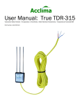
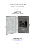
User Manual for CS3500 Controller
Water on Demand® 2-Wire Irrigation Controller
The CS3500 is an advanced computerized irrigation controller using
patented Digital TDT soil moisture sensors to accurately and efficiently
control irrigation. The CS3500 uses advanced 2-Wire system design and
is a powerful, yet flexible controller that can be monitored remotely over
the internet or phone line using Irrigation Manager™ Software.
Part Number: ACC-CON-WD64
Acclima, Inc.
1763 W Marcon Ln, Ste 175
Meridian, Idaho USA 83642
www.acclima.com
Table of Contents
Before you Begin
Installation
Controller
4
5
5
Mounting.................................................................................................... 5
Connecting the Power ............................................................................ 5
Phone Line (optional) ............................................................................. 6
2-Wire BUS ................................................................................................ 6
Zone Adapters..............................................................................................8
2 or 4 Zone Adapters ............................................................................. 8
16 or 32 Zone Adapters ........................................................................ 9
Moisture Sensors........................................................................................9
Sensor locations...................................................................................... 9
Sensor Installation ................................................................................ 10
Moisture Thresholds............................................................................. 11
Pressure Gauge, Flow Meter, Master Valve......................................11
Configuration
User Interface ............................................................................................12
Set Date and Time....................................................................................13
2-Wire Devices...........................................................................................13
Water Source .............................................................................................14
Water Restrictions ....................................................................................15
12
Daily Restrictions................................................................................... 16
Hourly Restrictions................................................................................ 16
Zones............................................................................................................17
Manual Watering ................................................................................... 18
Pause This Zone .................................................................................... 18
View Automatic Watering History ...................................................... 18
Test Valves .............................................................................................. 19
Zone Setup.............................................................................................. 19
Irrigation Manager Software..................................................................22
Operation
Auto/Run.....................................................................................................23
Zones............................................................................................................23
Soil Moisture Sensors .............................................................................24
Manual Programs .....................................................................................24
Set Manual Program............................................................................. 24
Run Manual Program ........................................................................... 25
Adjust Manual Program ....................................................................... 25
System Pause ............................................................................................26
-
toll free 866-887-1470 / fax 208-887-6368
|2
23
Event Pause................................................................................................26
Advanced Settings....................................................................................27
Flow Control................................................................................................27
Manage Zone Water Use..................................................................... 28
Manage Flow Meter.............................................................................. 28
Manage Pressure Meter...................................................................... 29
Manage Global Flow Settings ............................................................ 30
Glossary
Limited Product Warranty
NOTES
3| CS3500 Model Number: ACC-CON-WD64
30
33
34
www.acclima.com
Before you Begin
Water on Demand®
The Acclima CS3500 is a Water on Demand® irrigation system that
accurately measures soil moisture and controls an irrigation system with
up to 64 zones and 10 Acclima Digital TDT® Soil Moisture Sensors.
Typical irrigation timers are programmed to water at regular timed
intervals, whether water is needed or not. The Acclima CS3500 Water on
Demand® Controller waters only when water is needed by the plants.
2-Wire System
The Acclima CS3500 uses a patented 2-wire system allowing the
controller to communicate with all sensors, valves and accessories in the
system. The advanced 2-wire system saves copper wire at installation and
facilitates adding zones and upgrading landscaping without the need to
dig trenches to add more zone wires back to the controller. An existing
conventionally-wired system can be converted to a 2-wire system.
Flow Control
The Acclima CS3500 allows up to 4 zones to water simultaneously. To
avoid low pressure when watering multiple zones the flow rates of each
zone and the flow capacity of the water source are programmed into the
system. The Acclima CS3500 will automatically maximize the use of your
water supply without exceeding its capacity.
Sensors
Closed Loop Irrigation® (irrigation controlled by accurate moisture
feedback from the root zone) is made possible through soil moisture
sensors buried in the root zone of your lawns and shrubs. Acclima's Digital
TDT® Sensors provide stable, accurate soil moisture readings year after
year through widely varying soil temperature and soil chemistry conditions.
-
toll free 866-887-1470 / fax 208-887-6368
|4
Installation
Controller
Mounting
The control box may be installed indoors or outdoors. It must have access
to 110 volt power and to a #6 or #10 bare copper grounding conductor to
an exterior ground rod.
1. Open the front cover of
the controller. The
weather-tight seal may
make opening a little
difficult. Swing back the
display panel by pulling
gently on the two tabs at
the top and bottom right
of the display.
2. Mount the Control Box
Open the front cover
Stud Mount - Mount the
Control box with 2" wood
screws through the
center top and bottom
mounting holes.
Wall Board or Masonry
Mount - Use wallboard or
masonry anchors and
screws through the top
and the bottom center
and right mounting hole.
Mount the Controller
Connecting the Power
The Acclima control box is intended to be hard-wired with 110 volt power.
The controller incorporates a lightning arrestor that must be grounded
using #6 or #10 bare copper grounding conductor to an exterior grounding
rod. This wire is to be connected to the 'Earth' terminal in the controller
box.
5| CS3500 Model Number: ACC-CON-WD64
www.acclima.com
1. Attach a conduit
union and splice box to
the ½" transformer
nipple protruding from
the controller box.
Avoid excessive torque
on the transformer
nipple. Excessive force
could break the
transformer loose
inside the box. Make
sure the power to the
controller is off before
attempting any
electrical work.
2. Drill a hole to install a 1/2" conduit for a #6 or #10 bare copper
grounding conductor to an exterior mounted earth ground. Attach the
ground wire to the 'Earth' terminal inside the controller.
Phone Line (optional)
An optional phone line may be installed into the control box to
communicate with the controller from an offsite central control computer
(not pictured). The phone line could be an extension of an existing line that
can be shared by the controller since line usage for the irrigation system
will be minimal.
1. Drill a hole and install a 1/2"
conduit adapter. Run telephone
wire from the splice point
through the conduit and into
the control box.
2. Attach an RJ11 connector on
the end of the phone wire and
plug into the RJ11 jack in the
control box as shown.
2-Wire BUS
The Acclima system utilizes two 12 or 14-gauge underground sprinkler
wires to connect all solenoid valves and other system devices to the
-
toll free 866-887-1470 / fax 208-887-6368
|6
controller. There is no required configuration design for the two-wire
network; however, a full loop approach must not exceed a wire length of
1000 feet (if it does we recommend the broken loop approach instead).
2-Wire Broken Loop Design
2-Wire Star Design
Up to four 2-wire pairs may originate from the controller. Each wire pair
may have any number of branches (star approach). There are three
limitations. First, the wire route to the device furthest from the controller
should not exceed 4,000 feet. Second, the total amount of paired wire on
the system should not exceed 10,000 feet. Third, the wire size must be
sufficient to keep the voltage drop at the end of the run to less than 5
volts when maximally loaded.
Recommended Wire:
Special irrigation control cable designed to operate valve decoders
consisting of tin coated copper conductors, insulated with PVC and having a
high density polyethylene direct burial jacket. ie "Maxi pair"
Conductor:
Insulation:
Soft annealed copper Polyvinyl Chloride
conforming to ASTM B- conforming to UL
Standard 493 for TYPE
33
UF rated 60ºC
Jacket:
Impregnated
Polyethylene
Acclima recommends a 1 in 5' twist be applied to the wire throughout the
system to avoid electrical interference with controller communications.
All wiring connection should be made using grease caps, direct burial type,
water-proof connectors. Insure the wires are tightly twisted before installing
the connector.
7| CS3500 Model Number: ACC-CON-WD64
www.acclima.com
For installations with
wire runs exceeding
1000 feet, 12-gauge
wire is recommended,
the wires must be
rated for underground
feeder use. The
insulation on the wire
should be polyethylene
(PE).
Connecting the 2-Wire BUS to the Controller
Zone Adapters
Valves are connected to the two-wire bus using zone adapters inside the
valve box or near the CS3500.
2 or 4 Zone Adapters
Each adapter has a red and a white wire protruding from the bus side for
connection to the 2-wire bus. The valve end has one white wire (COM) and
2 or 4 black wires that connect to the valves. You will attach one black
wire to each individual valve. The valve end white wire is the common wire
connection for all valves connected to that adapter. Unused black wires
from zone adapters may be left with insulation attached, capped and
coiled neatly in the valve box for possible future use.
-
toll free 866-887-1470 / fax 208-887-6368
|8
2 or 4 Zone Adapter
2 or 4 Zone Adapter configuration
16 or 32 Zone Adapters
Acclima's 16-zone and 32-zone
adapters are usually used to
adapt an existing conventionallywired system to the CS3500 2wire controller. Each 16-zone and
32-zone adapter comes in a case
that can be mounted on the wall
near the controller. The adapters
have terminals for connecting the
2-wire system from the CS3500
controller to the adapter. The
terminal to which the white wire is
connected serves as the
'common' wire to the valves. The
zone wires from the valves
connect to the 16 or 32 terminal
points provided.
16-Zone Adapter 32-Zone Adapter
Moisture Sensors
Sensor locations
1. Select a location for sensor placement
Classify your irrigated area into full sun zones, full shade zones,
partial sun/shade zones and zones with varying soil types (sand vs.
9| CS3500 Model Number: ACC-CON-WD64
www.acclima.com
loam vs. clay.) It is best to install a sensor in one of each of these
classified areas. If you have a sloped hillside that faces south or west it
is advisable to place a sensor there also.
Sensor locations should be representative of the entire zone
throughout the entire day; however, it should favor areas in the zone
that receive the most sun.
Each sensor location should be well drained and not a low area
where water may collect.
Avoid large, dense, tree roots.
Avoid placing sensors within four feet of a sprinkler head or in an
area that may be watered by more than one zone.
For sloped areas, place sensors about 1/3 of the way down the
slope from the top in an area that receives the most sun (south or west
facing slope). Do not place sensors at the bottom of a slope or close to a
sidewalk where runoff may collect.
Use sensors sparingly to keep material and installation costs
down, however be sure to use sufficient sensors to cover major
microclimate and soil variations. A typical ratio of sensors to irrigation
zones would be one sensor for every 4 to 8 zones.
2. Installing sensors
Sensor Installation
2-Wire Connection
The wire should be
buried at least 8"
deep.
Coil the black wire in the valve box. Install the sensor no deeper than 4
inches.
Valve Connection
-
toll free 866-887-1470 / fax 208-887-6368
|10
Connect the Red and White
wires to the 2-wire system.
One valve wire connects to
the sensor black wire, the
other to the white wire.
Install the sensor no
deeper than 4 inches.
Moisture Thresholds
To properly set the threshold you will need to know the 'Field Capacity'
(water holding capacity) of the soil around the sensor. To determine Field
Capacity slowly soak the soil above the sensor with at least 10 gallons of
water. It is important that the area is very wet so that the water is standing
on the surface. Allow several hours for the water to drain into the subsoil.
To insure that the soil moisture has come down to 'Field Capacity' it is best
to do the soaking in the evening and then come back early in the morning
before the sun gets hot to measure Field Capacity. The next morning, after
flooding the sensor, take a moisture reading by rotating the CS3500 knob
to 'Soil Moisture Sensors', selecting the sensor and initiating a sensor
reading. This reading is your soil's Field Capacity. It represents the
maximum volumetric water content your soil can hold without percolating
to the subsoil. Set the sensor turn-on threshold to 75% of Field Capacity.
The turn-off threshold should be set at field capacity. Alternately you can
turn off the water after a fixed watering time. To do this set the upper
threshold at 20% above field capacity and set the 'Maximum Watering
Time' for the zone to the desired watering time.
Pressure Gauge, Flow Meter, Master Valve
The module and the master valve and flow meter are mounted in one or
more valve boxes near your water source. The master valve is the first
item upstream which is followed by the flow meter then the Acclima
module with the pressure gauge. The Flow Meter must be installed ten
straight pipe diameters downstream from the master valve and should be
followed by five straight pipe diameters before the Acclima Module that
houses the pressure gauge.
11| CS3500 Model Number: ACC-CON-WD64
www.acclima.com
The Data Industrial Series 200
Flow Meter comes from the
factory mounted in a "T". The "T"
should be glued into the pipe run
with the arrows facing in the
direction of the flow of water.
The "T" for the Acclima module is not supplied and must have a 1/8" NPT
female port for the pressure gauge to screw into. Screw the pressure
gauge into the "T" using Teflon tape. The module has three pairs of wires
emanating from it. The white and red pair connect to the 2-wire system
using direct burial DBY connectors (white to white and red to red). The red
and black pair of wires at the other end of the module connects to the red
and black wires on the flow meter respectively using direct burial DBY
connectors. The remaining black pair of wires connects to the master
valve. The master valve must use 24 volts AC at no more than 500 MA.
Configuration
User Interface
NOTE: Soft Keys are
labeled by symbols
near the bottom of the
display. Their function
changes with each new
screen.
User Interface
-
toll free 866-887-1470 / fax 208-887-6368
|12
Text Screen: You will use this
screen to adjust text fields
throughout the controller.
Use the Prev and Next
buttons to move through the
text options. Press the Adjust
Value keys to make your
selection. When finished
press the soft key Apply.
Set Date and Time
Turn the controller knob to
'Set Date and Time'.
1. Use the + and - Adjust
Value buttons to change the
date and time fields.
3. When finished press the
soft Save button
2-Wire Devices
Each 2-Wire device throughout the
system must be configured at the
controller, including sensors, flow
meters, and valve adapters.
1. Turn the controller dial to '2Wire System Devices
Add/Remove'. 'Add new Device'
appears highlighted. Press the +
key. The screen at the right
appears.
2. Use the Next/Prev keys to
select the first digit of the serial
number. Press + to enter the first
13| CS3500 Model Number: ACC-CON-WD64
www.acclima.com
digit.
3. Enter the subsequent digits of the serial number as in step 2.
4. Press the 'Apply' button. A
temporary screen will appear
indicating the type of device that
was detected. If the device is a
valve adapter another screen will
appear prompting you to identify
how it will be used: Zone Switch,
Master Valve, Pump Switch,
Emergency Shutoff, or Backflush
Switch. Highlight the selection and
press +.
5. Repeat 1 through 4, entering
serial numbers for all devices you
have attached to the 2-wire
system including valve adapters,
sensors and flow meter modules.
Water Source
The Acclima CS3500 allows up to 4 zones to water simultaneously if there
is sufficient water capacity from your source. In order to configure the
system to efficiently manage the water you must configure a water source.
Choose from the following two options:
Default Water Source: If you do not have a master valve installed on your
system then select the default water source. This setting assumes a
constant flow from a water main.
Master Valve:
NOTE: If you have more than one source of water the CS3500 will manage
multiple sources provided they are not interconnected. Each separate
source must provide water to its own unique group of zones. You will need
to use the Acclima Irrigation Manager Software to configure additional
water sources.
-
toll free 866-887-1470 / fax 208-887-6368
|14
1. Turn the controller dial to
'Master Valve'.
2. Press the + Adjust Value button
to edit the master valve.
3. Using the Prev and Next Keys
hard keys to choose default water
source or assign the Mater Valve.
When Finished Press the + Adjust
Value Button.
4. Next, Configure the Water
Source either the default or
Master Valve. You may change
the water source name as well as
adjust the maximum flow rate in
GPM (gallons per minute).
You can also test the valve
current from this screen. Simply
move to the Test Valve Current
field using the Prev and Next Keys
and press the adjust value
button. This will take you to a test
screen where you can test the
valve current of just the master
valve or all the system devices.
(SEE TEST VALVE SCREEN)
Water Restrictions
The Acclima CS3500 Water on Demand™ system will apply water the
instant the sensor detects the watering threshold has been crossed. This
could happen at any time of the day or any day of the week. You may not
want irrigation to occur during specific times of the day or on specific days.
To prevent watering when you do not want it you must create a Watering
Restriction. You can create as many of these as you wish and assign them
to the zones in any combination you need. Zones assigned to restrictions
will not water during the times specified by the restriction.
There are two types of restrictions that can be used to inhibit watering. A
restriction in either or both will prevent watering for the specified period.
15| CS3500 Model Number: ACC-CON-WD64
www.acclima.com
Daily Restrictions
Daily restrictions apply to the whole system and are not assignable to
individual zones. Your controller will not water during the restricted days.
1. Turn the controller dial to
'Daily Restrictions' to configure
year-round, day cycle, and
seasonal restrictions.
2. Use the hard keys to select
among the options and set the
system's daily restrictions.
3. Select Add a new Restriction
to create a new daily restriction.
Once the restriction is selected
you can adjust the following:
The controller will water all year
Seasonal: The controller will only water during your watering season
Start Date: The first day of your watering season
End Date: The last day of your watering season
Day Cycle:
Everyday
Even Days
Odd Day
Custom Days
Water Every _Days
4. Use can also change the name of the restriction from the panel. Select
the Change Restriction Name field and use the text screen to name your
restriction.
5. Press the soft Save key when complete.
Hourly Restrictions
Hourly restrictions control the time of day that watering will be allowed.
Each day of the week can be set up as desired. The generated restriction
-
toll free 866-887-1470 / fax 208-887-6368
|16
pattern can be assigned to whatever zones need it. Multiple restriction
patterns can be set up and assigned to different zones as desired.
The water drop signifies watering permitted, the X indicates restricted
watering.
1. Turn the controller dial to
'Hourly Restrictions' to configure
hourly restrictions.
2. Use the soft keys Prev Time and
Next Time to move between the
times on the controller. Use the
Prev and Next keys to move
between days of the week. Press
the + and - Adjust Value buttons to
change the water drops to an X
and vise versa.
3. After you have finished the
restriction table press the save
soft key.
Zones
With the devices installed onto the system and the water source and
restriction information entered you are ready to complete the system
configuration by setting up the details for each zone.
1. Turn the controller dial to any of
the 'Numbered Zones'. The 3rd soft
key selects which ring you are
accessing.
2. Use the Next/Prev buttons to
navigate through the configuration
options. Highlight the 'Zone Setup'
field and press the + key.
3. Use the Next/Prev buttons to
navigate through the options on the
Zone Setup screen. You can choose
the following options:
Manual Watering
Pause this Zone
17| CS3500 Model Number: ACC-CON-WD64
www.acclima.com
View Automatic Watering History
Test Valves
Zone Setup
Manual Watering
1. Use the + and - Adjust Values
buttons to change the manual
watering duration.
2. When finished, press the soft
Start Manual button to initiate
manual watering.
Pause This Zone
1. Use the + and - Adjust Values
buttons to change the pause zone
duration.
2. When finished, press the soft
Pause Zone button to pause the
zone's watering for the set
duration.
View Automatic Watering History
You can view the past history of
the zone by selecting the View
Automatic Watering History.
A list of the last several waterings
is displayed. You can view the
date and time the watering
began, plus the duration of the
watering.
-
toll free 866-887-1470 / fax 208-887-6368
|18
Test Valves
You can test and view all the
valve's readings in one easy to
use screen.
Test One
1. Use the Prev and Next buttons
to move to the desired valve.
2. Press the soft Test one button
to test and display the selected
valve's reading.
Test All
1. Press the soft Test All button to read and display all valve's reading.
Zone Setup
Each zone can be set up independently of other zones. The zone types are
very important as they determine the behavior of the zone and how it will
water. You must designate each zone to be one of the following zone
types:
Sensor
1. Use the Prev and Next buttons to
move through the field on the screen.
2. Press the + and - Adjust Value
buttons to change the values of the
fields.
3. You can use the soft Back button
at any time to go back to the Zones
screen.
4. To setup the zone as a Sensor
Zone adjust the following:
Run Time: Set the run time for this zone
Track Sensor: Indicate which sensor the zone will track
Set the upper soil moisture threshold for the sensor, or the turn off level.
Lower Threshold: Set the lower soil moisture threshold for the sensor, or
the turn on level.
19| CS3500 Model Number: ACC-CON-WD64
www.acclima.com
Percolation Time:
Soak Cycle:
Water For: Indicate the duration the zone will water until it stops to soak.
Soak For: Indicate the soak duration before the zone continues to water.
Water Restrictions: Indicate which restriction to use for this zone from the
list of restrictions you set previously.
Valve Current Sep Point
Water Source: Select the water source from the list of configured water
sources.
Normal Flow Rate
Critical Flow Rate
High Flow Rate
Low Flow Rate
Change Zone Name: Enables you to change the zone name by using the
test edit screen.
5. When finished making all changes press the soft Save button.
Dependant
1. Use the Prev and Next buttons to
move through the field on the
screen.
2. Press the + and - Adjust Value
buttons to change the values of the
fields.
3. You can use the soft Back button
at any time to go back to the Zones
screen.
4. To setup the zone as a Dependent
Zone adjust the following:
Track Sensor Zone: Indicate which sensor zone the zone will track
Tracking Ratio: Indicates the tracking duration. 100% and the zone will
water the same duration, 50% it will water half as long.
Soak Cycle: Turn the soak cycle option on or off.
Water For: Indicate the duration the zone will water until it stops to soak.
Soak For: Indicate the soak duration before the zone continues to water.
Water Restrictions: Indicate which restriction to use for this zone from the
list of restrictions you set previously.
Valve Current Sep Point
Water Source:
Normal Flow Rate
Critical Flow Rate
-
toll free 866-887-1470 / fax 208-887-6368
|20
High Flow Rate
Low Flow Rate
Change Zone Name: Enables you to change the zone name by using the
test edit screen.
5. When finished making all changes press the soft Save button.
Timer
1. Use the Prev and Next buttons
to move through the field on the
screen.
2. Press the + and - Adjust Value
buttons to change the values of
the fields.
3. You can use the soft Back
button at any time to go back to
the Zones screen.
4. To setup the zone as a Timer
Zone adjust the following:
Run Time: Set the run time for this zone
Water Every _Day _Hours: Set the time between waterings.
Soak Cycle:
Water For: Indicate the duration the zone will water until it stops to soak.
Soak For: Indicate the soak duration before the zone continues to water.
Water Restrictions: Indicate which restriction to use for this zone from the
list of restrictions you set previously.
Valve Current Sep Point
Water Source: Select the water source from the list of configured water
sources.
Normal Flow Rate
Critical Flow Rate
High Flow Rate
Low Flow Rate
Change Zone Name: Enables you to change the zone name by using the
test edit screen.
5. When finished making all changes press the soft Save button.
21| CS3500 Model Number: ACC-CON-WD64
www.acclima.com
Backflush
1. Use the Prev and Next buttons
to move through the field on the
screen.
2. Press the + and - Adjust Value
buttons to change the values of
the fields.
3. You can use the soft Back
button at any time to go back to
the Zones screen.
4. To setup the zone as a
Backflush Zone adjust the
following:
Run Time: Set the run time for this zone
After Operating:
Valve Current Set point:
Water Source: Select the water source from the list of configured water
sources.
Change Zone Name: Enables you to change the zone name by using the
test edit screen.
5. When finished making all changes press the soft Save button.
Irrigation Manager Software
The Acclima CS3500 can be configured by using the controller interface or
Acclima Irrigation Manger™ software connected to the controller through a
serial port. For instructions on configuration the Acclima CS3500 by the
Irrigation Manager please consult the software operation manual.
Irrigation Manager™ Software can be downloaded at www.acclima.com
-
toll free 866-887-1470 / fax 208-887-6368
|22
Operation
Auto/Run
The system is always in
Auto/Run mode even if the
controller dial is not positioned
here. From this screen you can
view the current status of all
zones or view error logs.
View Current Status of all Zones
1. Press the + Adjust Value
button to view zone status.
2. Use the Prev and Next
buttons scroll through the list of
zones.
3. When finished press the soft Back button.
View error logs
1. Press the Next button to move to View error logs and press the + Adjust
Value button.
2. Use the Prev and Next buttons scroll through the list of errors.
3. When finished press the soft Back button.
Zones
Use these switch positions to
set up and edit zones. Use the
soft button to cycle through
zones 1,13,25,37,49, and 61.
23| CS3500 Model Number: ACC-CON-WD64
www.acclima.com
Soil Moisture Sensors
You can view all the sensor's
readings in one easy to use
screen.
Read One Sensor
1. Use the Prev and Next buttons
to move to the desired sensor.
2. Press the soft Read one Sensor
button to read and display the
selected sensor's reading.
Read All Sensors
1. Press the soft Read All Sensors button to read and display all sensors'
reading.
Show Thresholds
Manual Programs
Set Manual Program
1. Turn the controller knob to the
'Manual Programs' setting.
2. Press the + Adjust value to
change the program.
3. Use the Prev and Next buttons to
choose a program to edit, or choose
Add new Programs to create a new
manual program.
4. Use the Prev and Next buttons to
move to the Step 1 field. The field to
the right shows the step type. Move
to the type field and press the + or Adjust Value buttons to change the
-
toll free 866-887-1470 / fax 208-887-6368
|24
step type.
5. Once the step type is selected you
can edit the step using the Prev and
Next buttons to move between fields
and the + or - Adjust Value buttons
to edit the step.
6. To build the second step move to
the Step field and pres the + Adjust
Value button to move to Step 2.
Repeat number 4 to edit Step 2.
7. Continue building steps until your
Manual Program is complete. The
final step should be End Program.
8. Rename your program by moving
to the Change Manual Program
Name field. Use the text edit screen
to rename your Manual Program.
9. Press the soft Save button when
finished.
Run Manual Program
1. Select the program you wish to run by using the + and - Adjust Values
button.
2. Press the soft Start Program button to run the program
Adjust Manual Program
While a Manual Program is running
you can skip ahead to the next
steps or repeat previously run steps.
You can also stop the program.
Use the soft keys to skip to the Prev
Step, Next Step, or Stop Program.
NOTE: If you select to Stop the
Program the Manual Program will
terminate. To restart the Program
press the soft Start Program button.
25| CS3500 Model Number: ACC-CON-WD64
www.acclima.com
System Pause
System pause will pause the entire
system for a set time.
To Pause the System
1. Use the Prev and Next buttons to
move between the days, hours, and
minutes fields.
2. Use the + and - Adjust Values
buttons to change the number of
days, hours, and minutes you want to
pause the system.
3. Press the soft Pause System
button to pause the system.
To Resume Operations
1. Press the soft Resume Auto button
to cancel the system pause and
resume automatic operations.
Event Pause
Rather than wait for the start of the event to place the system in pause
mode, you can schedule up to 6 future events using this function. At the
day and time you schedule the system will shut down all watering for the
duration you specify.
1. Turn the knob to the 'Event Pause'
setting.
3. Use the Prev and Next buttons to
move between field and the + and Adjust Value fields to edit the event.
Set the start date, time, and the
-
toll free 866-887-1470 / fax 208-887-6368
|26
duration of the paused event.
4. Press the soft Save button to save the changes and the soft Back
button to move back to create a new event.
Advanced Settings
Contrast Adjustment: This field adjusts the display contrast.
Select Display Language: Select between English, French, Italian,
Portuguese, or Spanish.
Minutes between Sensor Logs: Changes the interval of how often sensor
readings are saved in the data logging memory.
Enable Modem Answer: Turns modem on or off.
: Updates the panel with fresh configuration information. Not generally
needed, this function happens automatically.
1. Use the Prev and Next buttons to
move between fields.
2. Use the + and - Adjust Value
buttons to change the fields.
3. Press the soft Save button when
finished to save your changes.
Flow Control
When multiple zones are due for water the CS3500 will turn on a first
zone. If you have a flow meter installed on that source it will measure the
water being consumed by the zone and compare it to the available water
from the source. If you do not have a flow meter installed it will use the
zone flow rate you have programmed for that zone. If the source capacity
is not fully used the CS3500 will find another zone waiting for water
wherein the total flow of the two zones does not exceed the capacity of the
source. And likewise a third and fourth zone will be added if the source
has sufficient capacity. You can limit the maximum number of zones that
will be on at one time. To do this highlight 'Manage Global Flow Settings'
from the Flow Control screen and press +. Then highlight the field "Zones
watering at a time" and increment or decrement the number.
27| CS3500 Model Number: ACC-CON-WD64
www.acclima.com
Manage Zone Water Use
1. Use the Prev and Next buttons to
move through the fields.
2. Press the + and - Adjust Values
buttons to change the settings.
3. When you are finished with the
flow meter settings press the soft
Save key.
Manage Flow Meter
Note that the Acclima CS3500 controller and Flow Meter Adapter support
the Data Industrial 200 series flow meters. The meter, adapter and master
valve (if you use one) must be installed in accordance with the instructions
in the INSTALLATION section.
Water Source: You must specify the water source on which you installed
the flow meter. When you select this field and press + a pull down list of
your installed water sources will appear. Select the one to which the
flow meter is attached.
Diameter: This is the diameter of the Flow Meter. The standard diameters
available in the Data Industrial 200 series are 1", 1.5", 2", 3", 4", 6", 8",
10", 12" and 16". Select the size you have installed.
Set Source Flow to Recommended: The flow capacity of the flow meter will
default to the capacity of the water source to which it is attached.
However the pipe diameter you specified with the flow meter provides
an alternate capacity derived from standards of recommended flow
rates for various pipe diameters. If you wish to use the recommended
standard instead of the default you programmed for the water source
press + while this field is highlighted. That will set the flow capacity to a
rate corresponding to 5 feet per second flow velocity in your water main.
Read Flow Meter: If you wish to
read the current flow rate (with one
or more zones running) press the
soft Read Flow Meter button.
1. Use the Prev and Next buttons to
move through the fields.
2. Press the + and - Adjust Values
buttons to change the settings.
-
toll free 866-887-1470 / fax 208-887-6368
|28
3. When you are finished with the
flow meter settings press the soft
Save key.
Manage Pressure Meter
If you entered the serial number of a pressure meter in the 2-wire System
Devices setup it will appear on this screen. You can set high and low
pressure limits. If the water pressure exceeds the high limit you specify
you can program the system to shut off the master valve to protect your
pipes. If the pressure falls below the low limit you can program the system
to stop watering. It is often futile to water with low pressure because the
sprinkler heads do not cover all of the turf and brown spots will develop in
the uncovered areas.
Change Meter Name: You can give the pressure meter a name by
selecting this field then using the alphanumeric entry screen that
follows.
Water Source: You must specify the water source to which the pressure
meter is attached.
High Threshold: Set the highest pressure to which you will allow your
system to be subjected to. The use of this limit to shut off the master
valve is enabled or disabled under Manage Global Flow Settings.
Set the lowest pressure you will allow your system to operate under. The
use of this setting to stop watering at low pressure is enabled or
disabled under Manage Global Flow Settings.
Read Pressure: You can take a
current pressure reading by
pressing the soft Read Pressure
button.
1. Use the Prev and Next buttons
to move through the fields.
2. Press the + and - Adjust Values
buttons to change the settings.
3. When you are finished with the
pressure meter settings press the
soft Save key.
29| CS3500 Model Number: ACC-CON-WD64
www.acclima.com
Manage Global Flow Settings
Zones Watering at a Time: Set the maximum number of zones that you will
allow the controller to turn on simultaneously. This number is
automatically limited by the flow capacity of your source and the flow
rates of your zones, but if you wish to place your own constraints on
multiple zone watering this is the place to do it.
Seconds Valve Delay: The CS3500 provides a programmable delay in the
time from when a valve turns off until the next valve turns on. This is
sometimes required to keep water pressure high enough to shut down
the first valve. It is also used in recharging ponds and wells between
zone watering periods. You can enter up to 254 seconds in this field.
Enable Flow and Pressure Meters: Check this field to enable the flow and
pressure meters.
High Flow Shutoff: If you check this field the CS3500 will shut off the
master valve whenever the MV flow setting is exceeded by 50%. It will
likewise shut down any zone if the zone flow rate is exceeded by 50%.
Low Flow Shutoff: If you check this option the CS3500 will report 'Low
Water Flow on Zone X' whenever the zone flow rate is less than 50% of
the nominal zone setting.
High Pressure Shutoff: If you check this option the CS3500 will shut off
the master valve whenever the water pressure exceeds the high limit
you specified in the Pressure Meter Setup.
Low Pressure Shutoff: If you check this option the CS3500 will not water
when the water pressure is below the low pressure limit you specified in
the Pressure Meter Setup.
1. Use the Prev and Next buttons
to move through the fields.
2. Press the + and - Adjust Values
buttons to change the settings.
Glossary
Acclima Pronounced as in Acclimatize. Manufactures of the world's best
absolute moisture sensors.
Automatic circuit protection A built-in circuit protection circuit designed to
prevent damaged to the controller caused by a faulty valve solenoid or
pump start relay. The instant an overload current condition is
-
toll free 866-887-1470 / fax 208-887-6368
|30
detected, the affected zone is turned OFF and the next zone in the
watering sequence is turned ON.
Back Flush The process of flowing water backwards through a filter to
remove trapped debris and restore the filter for ongoing use.
Calendar Schedule A Calendar Schedule enables you to select specific
days of the week to water, for example, Monday, Wednesday and
Friday. This is a 14 day schedule which starts on Sunday and ends on
Saturday.
Dependent Zone A zone that is watered based on data from a reference
zone. Setting up dependent zones saves money on sensor costs. One
reference zone with a sensor can effectively control irrigation in
several other dependent zones provided all such grouped zones are
similar in soil type, microclimate and sprinkler precipitation rate.
Field Capacity The maximum volumetric water content that can be held in
soil against the pull of gravity. Amounts greater than this are pulled
downward into the subsoil and groundwater and are wasted.
Flow Meter A device used to measure the rate of water flow in a hydraulic
system.
Management Allowed Depletion The minimum volumetric water content
required to prevent stress in growing plants. If the plant does not
receive water it will continue to pull moisture from the soil under
stress until the Permanent Wilt Point is reached where the plant dies.
Manual Program A watering program that waters one or more zones in a
sequence specified by the user and which is started manually.
Master Valve
Master Valve Circuit At the beginning of each irrigation cycle, before the
first sprinkler valve is turned on, the master valve circuit is energized
to open the system master valve.
Microclimate The climatic conditions of a small plot of irrigated property.
The conditions include the amount and intensity of sunlight, wind
exposure and velocity, relative humidity, inclination, and temperature.
These factors along with soil type and plant type determine the water
needs of the plants growing in the microclimate. A typical landscaped
property includes several widely different microclimates. A soil
moisture sensor should be installed in each microclimate type.
Odd/Even Schedule The Odd/Even schedule enables odd or even
numbered days of the month as watering days.
Permanent Wilt Point The soil moisture level where plant life dies.
Pump Control Circuit The pump control circuit is energized to start the
pump whenever a zone is active that has been configured to use the
pump.
Pump Relay A electrical device with a low voltage input used to turn on a
water pump on command from a controller.
Rain Delay This feature enables all watering operations on timer
programs (A, B, C, and D) to be delayed from 1 to 14 days.
31| CS3500 Model Number: ACC-CON-WD64
www.acclima.com
Rain Sensor A rain sensor is a device required by some municipalities to
suspend irrigation during a rain storm. Such a device can be
connected directly to the SC24/36. When water activates the rain
sensor the SC24/36 will suspend all watering operations, including
timer and sensor programs for as long as the sensor is activated. The
SC24/36 accommodates normally closed, common-interrupting type
rain sensors.
Saturation Saturation is the soil moisture level where the water begins to
puddle on the surface due to the inability of the soil to assimilate any
more water. The saturation water causes runoff and/or leeching to
the subsoil until the moisture level reaches field capacity. Saturation
irrigation wastes water, leeches out nutrients, contaminates
groundwater and suffocates roots.
Scheduling Planning how long to water (zone run times), when to water
(program start time) and which days to water (watering days).
Soak Cycle A Soak Cycle is used for hillsides or slopes to avoid surface
runoff by watering for a short period of time, stopping and allowing the
water to soak in, then continuing another short period of time until the
full required amount of water has been applied.
Soil Moisture Sensors
Solenoid Valve An electrical and hydraulic device that turns water on and
off based on an electrical input.
Start Time A start time is the time of day selected to begin the watering
cycle. Each program (A, B, C, and D) and each sensor program (S1,
S2, S3…S36) can have up to 6 separate start times.
Suspended Cycle® Irrigation The SC24/36 operates as a Suspended
Cycle® controller when using sensor programs. The controller uses
programs to control the time and date of watering but then suspends
irrigation if the soil moisture level is above the user set threshold
when the program start time arrives. Irrigation is allowed at the next
start time when the moisture level drops below the threshold.
Terminal Block Connection points for valve wires, common wires, master
valve, pumps and other accessories located behind the front panel of
the controller.
Volumetric Water Content The amount of water in soil as measured
volumetrically. 25% water content measured as VWC means that in
every cubic foot of soil there are 0.25 cubic feet of water.
Valve Adapter (or Zone Adapter) An electronic device that interfaces a
standard solenoid valve or pump relay to a 2-wire system.
Valve Common Wire The common wire is the circuit that is common to all
the valves in the system. Each valve has one wire attached directly to
the common. The SC24/36 uses this wire for communication from the
controller to the sensors, and flow meters throughout the system. The
other wire connected to the valve that is not common to the other
valves is often called the Zone Wire.
Water Budget Water budget is a seasonal adjustment that enables the
runtime of all zones only to be adjusted in 5% increments from 10% to
-
toll free 866-887-1470 / fax 208-887-6368
|32
200%. For selected months, the timer program duration is multiplied
by the water budget percentage and activated for that adjusted
duration.
Water on Demand® Irrigation Acclima manufactures both Suspended
Cycle® and Water on Demand controllers (see Suspended Cycle®
Controller). A Water on Demand Controller applies water immediately
when the soil moisture level falls below the watering threshold provided it is not restricted from watering at that time. It does not use
Programs. Allowable watering windows are set up in which the
controller can apply water when it is needed.
Watering Threshold The volumetric water content of soil where a watering
cycle is initiated by the CS3500. The user sets this limit for the
reference zone. It is normally the Management Allowable Depletion
level of water content.
Watering Program A watering program (or schedule) is the information
store in the controller memory that determines when an automatic
water cycle will occur and how long each zone will water. The
controller requires three basic instructions to operate automatically. A
watering program consists of four data points:
What days to water—watering days
What time to water—start time
How long to water—run time
Sensor threshold (for sensor programs)
NOTE: Sensor programs may or may not water. They are dependant on
soil moisture levels.
Watering Day The days of the week selected to water.
Zone Each solenoid valve controls a specific group of sprinkler heads
called a watering zone. The zones are generally laid out and installed
according to the type of plant material to be watered, such as lawn or
flower bed and sprinkler head type. Each valve is connected to a
numbered terminal within the controller, identifying it as Zone 1, Zone
2…Zone 36.
Zone Run Time The length of time a zone will operate during a watering
cycle. Run time can be set from 1 minute to 18 hours.
Limited Product Warranty
Your controller is warranted for two years from date of purchase to be free
of defective materials and workmanship, provided it is used within the
working specifications for which the product was designed and under
normal use and service. Unless installed by an authorized Acclima trained
technician, Acclima assumes no responsibility for installation. Acclima also
assumes no responsibility for removal or unauthorized repair. Acclima's
liability under this warranty is limited solely to replacement or repair of
defective parts, and Acclima will not be liable for any crop or other
consequential damages resulting from any defects in design or breach of
warranty. THIS WARRANTY IS EXPRESSLY IN LIEU OF ALL OTHER
33| CS3500 Model Number: ACC-CON-WD64
www.acclima.com
WARRANTIES, EXPRESS OR IMPLIED, INCLUDING THE WARRANTIES OF
MERCHANTABILITY AND FITNESS FOR PARTICULAR PURPOSES and of all
other obligations or liabilities of manufacturer. No agent, employee or
representative of the manufacturer has authority to waive, alter or add to
the provisions of warranty, nor to make representations or warranty not
contained herein.
Should you have any claim under this warranty, please contact Acclima's
warranty desk by calling toll free 866-887-1470 for prompt assistance.
NOTES
-
toll free 866-887-1470 / fax 208-887-6368
|34
35| CS3500 Model Number: ACC-CON-WD64
www.acclima.com
Acclima, Inc.
1763 W Marcon Ln, Ste 175
Meridian, Idaho USA 83642
www.acclima.com
toll free 866-887-1470
fax 208-887-6368
User Manual for CS3500 Controller 4/9/09 Rev 6
-
toll free 866-887-1470 / fax 208-887-6368
|36