1
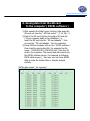
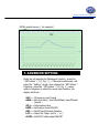
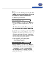
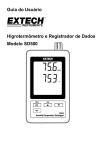
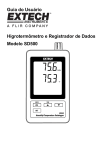
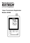
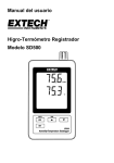
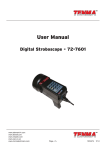
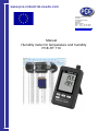
www.pce-industrial-needs.com
Tursdale Technical Services Ltd
Unit N12B
Tursdale Business Park
Co. Durham
DH6 5PG
United Kingdom
Phone: +44 ( 0 ) 191 377 3398
Fax: +44 ( 0 ) 191 377 3357
[email protected]
http://www.industrial-needs.com/
Manual
Humidity meter for temperature and humidity
PCE-HT 110
[email protected]
Your purchase of this HUMIDITY/BAROMETER/TEMP. Monitor with SD CARD datalogger marks a
step forward for you into the field of precision measurement. Although this datalogger is a
complex and delicate instrument, its durable structure will allow many years of use if proper
operating techniques are developed. Please read the following instructions carefully and always
keep this manual within easy reach.
TABLE OF CONTENTS
1. FEATURES.................................................................. 1
2. SPECIFICATIONS.........................................................1
3. FRONT PANEL DESCRIPTION....................................... 4
3-1 Display..................................................................4
3-2 Logger button, Enter button................................... 4
3-3 ▲ button, Time button...........................................4
3-4 ▼ button...............................................................4
3-5 SET button............................................................ 4
3-6 Humidity/Temp. sensor.......................................... 4
3-7 Hanging holes........................................................4
3-8 Stand.................................................................... 4
3-9 Battery cover/Battery compartment.........................4
3-10 Screw of the battery cover....................................4
3-11 Reset button........................................................4
3-12 RS-232 output terminal........................................ 4
3-13 SD card socket.....................................................4
3-14 DC 9V power adapter input socket........................ 4
3-15 Hanging unit ( with sticker )................................. 4
4. MEASURING PROCEDURE............................................ 5
5. DATALOGGER............................................................. 5
5-1 Preparation before execute datalogger function....... 5
5-2 Datalogger........................................................... 7
5-3 Check time information.......................................... 7
5-4 SD Card Data structure.......................................... 8
6. Saving data from the SD card to the computer..............9
7. ADVANCED SETTING...................................................10
7-1 SD memory card Format.........................................11
7-2 Set clock time ( Year/Month/Date, Hour/Minute/
Second ).............................................................. 11
7-3 Set sampling time.................................................. 12
7-4 Set beeper sound ON/OFF......................................12
7-5 Set SD card Decimal character................................13
7-6 Select the Temp. unit to ℃ or ℉............................ 14
7-7 Set RS232 data output ON/OFF...............................14
8. POWER SUPPLY from DC ADAPTER.............................. 15
9. BATTERY REPLACEMENT............................................. 15
10. SYSTEM RESET......................................................... 15
11. RS232 PC serial interface........................................... 16
12. PATENT.................................................................... 17
2
[email protected]
1. FEATURES
* Monitor with real time data logger, save the measuring
data along the time information ( year, month, date,
minute, second ) into the SD memory card and can be
down load to the Excel, extra software is no need.
User can make the further data or graphic analysis by
themselves.
* Show Humidity and Temperature value in the same LCD.
* 0.1 %RH resolution for the humidity reading,
0.1 degree resolution for the Temp. reading.
* Used the precision capacitance type humidity sensor,
professional and high accuracy.
* SD card capacity : 1 GB to 16 GB.
* Sampling adjustment : 5/10/30/60/120/300 seconds
and auto function.
* Large LCD display, easy readout.
* Microcomputer circuit, high reliability.
* Low power consumption and long battery life when
use battery power.
* DC 1.5V ( UM-4, AAA ) battery x 6 PCs or DC 9V
adapter in.
* RS232/USB computer interface available.
* Patented
2. SPECIFICATIONS
2-1 General Specifications
Circuit
Display
Measurement
Memory Card
Custom one-chip of microprocessor LSI
circuit.
LCD size : 60 mm x 50 mm
Humidity and Temperature
SD memory card, 1 GB to 16 GB.
3
[email protected]
Datalogger
5/10/30/60/120/300/600 seconds
Sampling Time or Auto.
* Default sampling time is 60 seconds.
* The " Auto " sampling . means when
the measuring value is changed ( > ±
1 %RH or > ± 1 ℃ ) will save the
data one time only.
Advanced
setting
Update Time
of Display
Data Output
Operating
Temperature
Operating
Humidity
Power Supply
* SD memory card Format
* Set clock time ( Year/Month/Date, Hour/Minute/
Second )
* Set sampling time
* Set beeper sound ON/OFF
* Set SD card Decimal character
* Select the Temp. unit to ℃ or ℉
* Set RS232 data output ON/OFF
Approx. 1 second if measuring data
is changed.
RS 232/USB PC computer interface.
* Connect the optional RS232 cable
UPCB-02 will get the RS232 plug.
* Connect the optional USB cable
USB-01 will get the USB plug.
0 to 50 ℃.
Less than 85% R.H.
* AAlkaline or heavy duty DC 1.5 V battery
( UM4, AAA ) x 6 PCs, or equivalent.
* ADC 9V adapter input. ( AC/DC power
adapter is optional ).
Battery life
Weight
Dimension
Accessories
Included
Optional
Accessories
If use the new battery ( alkaline type )
and sampling time set to 60 seconds,
the battery life will be > one month
typically.
282 g/0.62 LB.
132 x 80 x 32 mm
( 5.2 x 3.1 x 1.3 inch )
Instruction manual........................... 1 PC
Hanging unit ( with sticker )..............1 PC
SD Card ( 2 GB ).
AC to DC 9V adapter.
USB cable, USB-01.
RS232 cable, UPCB-02.
Data Acquisition software, SW-U801-WIN.
4
[email protected]
2-2 Electrical Specifications (23± 5 ℃)
Humidity
Range
Resolution
Accuracy
10 % to 95 % R.H.
0.1 % R.H.
≧70% RH :
± (3% reading + 1% RH).
< 70% RH :
± 3% RH.
Temperature
Range
Resolution
Accuracy
0 ℃ to 50 ℃,32 ℉ to 122 ℉.
0.1 degree
℃ - 0.8 ℃.
℉ - 1.5 ℉.
@ Above specification tests under the environment RF Field Strength
3. than
FRONT
PANEL
less
3 V/M & frequency
less DESCRIPTION
than 30 MHz only.
Fig. 1
5
[email protected]
3-1 Display
3-2 Logger button, Enter button
3-3 ▲ button, Time button
3-4 ▼ button
3-5 SET button
3-6 Humidity/Temp. sensor
3-7 Hanging holes
3-8 Stand
3-9 Battery cover/Battery compartment
3-10 Screw of the battery cover
3-11 Reset button
3-12 RS-232 output terminal
3-13 SD card socket
3-14 DC 9V power adapter input socket
3-15 Hanging unit ( with sticker )
4. MEASURING PROCEDURE
1) Install the batteries into the battery compartment :
* Loose the " Screw of the battery cover " ( 3-10, Fig. 1 )
and take away the " Battery Cover " ( 3-9, Fig. 1 ) from
the meter.
* Replace with DC 1.5 V battery ( UM4/AAA, Alkaline/Heavy
duty type ) x 6 PCs, and reinstate the cover.
* Make sure the battery cover is secured after changing
the battery.
2) The " Display " ( 3-1, Fig. 1 ) will show both the
humidity and the temperature value that sensing from
Humidity/Temp. sensor " ( 3-6, Fig. 1 ).
5. DATALOGGER
5-1 Preparation before execute datalogger function
a. Insert the SD card
Prepare a " SD memory card " ( 1 GB to 16 GB, optional ),
insert the SD card into the " SD card socket " ( 3-13, Fig. 1)
with the correct direction exactly.
b. SD card Format
If SD card just the first time use into the meter, it
recommend to make the " SD card Format " at first,
please refer chapter 7-1 ( page 11 ).
c. Time setting
If the meter is used at first time, it should to adjust the
clock time exactly, please refer chapter 7-2 ( page 11 ).
[email protected]
d. Decimal format setting
The numerical data structure of SD card is
default used the " . " as the decimal, for
example "20.6" "1000.53" . But in certain
countries ( Europe ...) is used the " , " as the
decimal point, for example " 20, 6 "
"1000,53". Under such situation, it should
change the Decimal character at first, details
of setting the Decimal point, refer to Chapter
7-5, page 13.
e. 3 Information of LCD display
* If the Display show :
CHCArd
It means that the SD card exist the problem
or the SD card memory is full, it should
change SD memory card.
* If the Display show :
LobAt
It means that the battery is low voltage.
Under such condition, the Datalogger
function is disable.
* If the Display show :
no
CArd
It means that the SD card is not plugged
into the meter.
6
[email protected]
[email protected]
5-2 Datalogger
a. Start the datalogger
Press the " Logger button ( 3-2, Fig. 1 ) > 2 seconds
continuously, until the Display show the indicator "
DATALOGGER ", release the " Logger Button " ( 3-2, Fig.
1 ), then the measuring data along the time information
will be saved into the memory circuit.
Remark :
* How to set the sampling time, refer to Chapter 7-3,
page 12.
* How to set the beeper sound is enable, refer to
Chapter 7-4, page 12.
c.. Finish the Datalogger
During execute the Datalogger function ( Display show the
" Datalogger " indicator ), press the " Logger button " ( 3-2,
Fig. 1 ) > 2 seconds continuously, until the Display
indicator " DATALOGGER " is disappeared, release the
" Logger Button " will finish the Datalogger function.
Before take away the SD card from the
meter, it should execute the
procedures of " Finish the Datalogger ",
otherwise some existing recent save
data may loss.
5-3 Check time information
Press " Time button " ( 3-3, Fig. 1 ) > 2 seconds
continuously, the LCD display will present the time
information of Year/Month/Date, Hour/Minute/Second and
the sampling value.
[email protected]
5-4 SD Card Data structure
1) When the first time, the SD card is used into the meter,
the SD card will generate a folder :
HTC01
2) If the first time to execute the Datalogger, under the
route HTC01\, will generate a new file name
HTC01001.XLS.
After exist the Datalogger, then execute again, the data
will save to the HTC01001.XLS until Data column reach
to 30,000 columns, then will generate a new file, for
example HTC01002.XLS
3) Under the folder HTC01\, if the total files more
than 99 files, will generate anew route, such as
HTC02\ ........
4) The file's route structure :
HTC01\
HTC01001.XLS
HTC01002.XLS
.....................
HTC01099.XLS
HTC02\
HTC02001.XLS
HTC02002.XLS
.....................
HTC02099.XLS
HTCXX\
.....................
.....................
Remark :
XX : Max. value is 10.
[email protected]
6. Saving data from the SD card
to the computer ( EXCEL software )
1) After execute the Data Logger function, take away the
SD card out from the " SD card socket " ( 3-13, Fig. 1 ).
2) Plug in the SD card into the Computer's SD card slot
( if your computer build in this installation ) or
insert the SD card into the " SD card adapter ". then
connect the " SD card adapter " into the computer.
3) Power ON the computer and run the " EXCEL software ".
Down load the saving data file ( for example the file
name : HTA01001.XLS, HTA01002.XLS ) from the SD
card to the computer. The saving data will present into
the EXCEL software screen ( for example as following
EXCEL data screens ) , then user can use those EXCEL
data to make the further Data or Graphic analysis
usefully.
EXCEL data screen ( for example )
[email protected]
EXCEL graphic screen ( for example )
7. ADVANCED SETTING
Under do not execute the Datalogger function, press the
" SET button " ( 3-5, Fig. 1 ) > 2 seconds continuously will
enter the " Setting " mode., then release the " SET button ".
Following press the " SET button " (3-5, Fig. 1 ) once a
while in sequence to select the seven main function, the
display will show :
Sd F..... SD memory card Format
dAtE......Set clock time ( Year/Month/Date, Hour/Minute/
Second )
SP-t...... Set sampling time
bEEP.....Set beeper sound ON/OFF
dEC.......Set SD card Decimal character
t-CF...... Select the Temp. unit to ℃ or ℉
rS232....Set RS232 data output ON/OFF
[email protected]
Remark :
During execute the " Setting " function, if within
5 seconds , do not press any buttons further, the
LCD Display will return to normal screen.
7-1 SD memory card Format
When the Display show " Sd F "
1) Use the " ▲ Button " ( 3-3, Fig. 1 ) or " ▼ Button " (
3-4, Fig. 1 ) to select the upper value to " yES " or
" no ".
yES - Intend to format the SD memory card
no - Not execute the SD memory card format
2) If select the upper to " yES ", press the " Enter Button
" ( 3-2, Fig. 1 ) once again, the Display will show text
" yES Enter " to confirm again, if make sure to do the
SD memory card format, then press " Enter Button "
once will format the SD memory clear all the existing
data that already saving into the SD card.
7-2 Set clock time ( Year/Month/Date,
Hour/Minute/ Second )
When the Display show " dAtE "
1) Use the " ▲ Button " ( 3-3, Fig. 1 ) or " ▼ Button "
( 3-4, Fig. 1 ) to adjust the value ( Setting start from
Year value ). After the desired value is set, press the
" Enter button " ( 3-2, Fig. 1 ) once will going to
next value adjustment ( for example, first setting
value is Year then next to adjust Month, Date, Hour,
Minute, Second value ).
[email protected]
Remark :
The adjusted unit will be flashed.
2) After set all the time value ( Year, Month, Date, Hour,
Minute, Second ), press the " SET button " ( 3-5, Fig.
1 ) once will save the time value, then the screen will
jump to Sampling time " setting screen ( Chapter 7-3 ).
Remark :
After the time value is setting, the internal clock will
run precisely even Power off if the battery is under
normal condition ( No low battery power ).
7-3 Set sampling time
When the Display show " SP-t "
1) Use the " ▲ Button " ( 3-3, Fig. 1 ) or " ▼ Button "
( 3-4, Fig. 1 ) to adjust the sampling value :
5 seconds, 10 seconds, 30 seconds, 60 second,
120 seconds, 300 seconds, 600 seconds Auto.
After the desired value is set, press the " Enter Button "
( 3-2, Fig. 1 ) to save the adjusting value with default.
Remark :
The " Auto " sampling time means when the measuring
value is changed ( > ± 1 %RH or > ± 1 ℃ ) will save
the data to the memory circuit one time.
7-4 Set beeper sound ON/OFF
When the Display show " bEEP "
1) Use the " ▲ Button " ( 3-3, Fig. 1 ) or " ▼ Button "
( 3-4, Fig. 1 ) to select the data to " yES " or " no ".
[email protected]
yES - Meter's beep sound will be ON with default
when save each data.
no - Meter's beep sound will be OFF with default.
when save each data.
2) After select the upper text to " yES " or " no ", press the
" Enter Button " ( 3-2, Fig. 1 ) will save the setting
function with default.
7-5 Decimal point of SD card setting
When the Display show " dEC "
The numerical data structure of SD card is used the " . "
as the decimal with default, for example "20.6"
"1000.53" . But in certain countries ( Europe ...) is
used the " , " as the decimal point, for example " 20,6 "
"1000,53". Under such situation, it should change the
Decimal character at first.
1) Use the " ▲ Button " ( 3-3, Fig. 1 ) or " ▼ Button "
( 3-4, Fig. 1 ) to select the upper text to " USA " or
" Euro ".
USA - Use " . " as the Decimal point with default.
Euro - Use " , " as the Decimal point with default.
2) After select the text to " USA " or " Euro ",
press the " Enter Button " ( 3-2, Fig. 1 ) will save the
setting function with default.
[email protected]
7-6 Select the Temp. unit to ℃ or ℉
When the Display show " t-CF "
1) Use the " ▲ Button " ( 3-3, Fig. 1 ) or " ▼ Button "
( 3-4, Fig. 1 ) to select the upper Display text to " C " or
" F ".
C - Temperature unit is ℃
F - Temperature unit is ℉
2) After Display unit is selected to " C " or " F ", press the
" Enter Button " ( 3-2, Fig. 1 ) will save the setting
function with default.
7-7 Set RS232 data output ON/OFF
When the Display show " rS232 "
1) Use the " ▲ Button " ( 3-3, Fig. 1 ) or " ▼ Button "
( 3-4, Fig. 1 ) to select the upper Display text to "yES " or
" no ".
yES - RS-232 output terminal ( 3-12, Fig. 1 )
will send the RS232 signal output.
no - RS-232 output terminal ( 3-12, Fig. 1 )
will not send the RS232 signal output.
2) After Display text is selected to " yES " or " no ",
press the " Enter Button " ( 3-2, Fig. 1 ) will save the
setting function with default.
[email protected]
8. POWER SUPPLY from DC
ADAPTER
The meter also can supply the power supply from the
DC 9V Power Adapter ( optional ). Insert the plug of
Power Adapter into " DC 9V Power Adapter Input Socket
" ( 3-14, Fig. 1 ).
9. BATTERY REPLACEMENT
1) When the left corner of LCD display show "
", it
is necessary to replace the battery. However, in-spec.
measurement may still be made for several hours after
low battery indicator appears before the instrument
become inaccurate.
2) Loose the " Screw of the battery cover " ( 3-10, Fig. 1 )
and take away the " Battery Cover " ( 3-9, Fig. 1 ) from
the instrument and remove the battery.
3) Replace with DC 1.5 V battery ( UM4/AAA,
Alkaline/heavy duty ) x 6 PCs, and reinstate the cover.
4) Make sure the battery cover is secured after changing
the battery.
10. SYSTEM RESET
If the meter happen the troubles such as :
CPU system is hold ( for example, the key button can
not be operated... ).
Then make the system RESET will fix the problem.
The system RESET procedures will be either following
method :
During the power on, use a pin to press the " Reset
Button " ( 3-11, Fig. 1 ) once a while will reset the
circuit system.
[email protected]
11. RS232 PC SERIAL INTERFACE
The instrument has RS232 PC serial interface via a 3.5 mm
terminal ( 3-12, Fig. 1 ) if the RS232 function already select
to " ON ", refer to chapter 7-7, page 14.
The data output is a 16 digit stream which can be
utilized for user's specific application.
A RS232 lead with the following connection will be
required to link the instrument with the PC serial port.
Meter
PC
(9W 'D" Connector)
Center Pin..........................Pin 4
(3.5 mm jack plug)
Ground/shield.......................Pin 2
2.2 K
resistor
Pin 5
The 16 digits data stream will be displayed in the
following format :
D15 D14 D13 D12 D11 D10 D9 D8 D7 D6 D5 D4 D3 D2 D1 D0
Each digit indicates the following status :
D0
End Word
D1 & D8 Display reading, D1 = LSD, D8 = MSD
For example :
If the display reading is 1234, then D8 to
D1 is : 00001234
[email protected]
D9
Decimal Point(DP), position from right to the
left
0 = No DP, 1= 1 DP, 2 = 2 DP, 3 = 3 DP
D10
Polarity
0 = Positive 1 = Negative
D11 & D12 Annunciator for Display
℃ = 01
℉ = 02
% RH = 04
D13
When send the upper display data = 1
When send the lower display data = 2
D14
4
D15
Start Word
RS232 FORMAT : 9600, N, 8, 1
Baud rate
Parity
Data bit no.
Stop bit
9600
No parity
8 Data bits
1 Stop bit
12. PATENT
The meter ( SD card structure ) already
get patent or patent pending in following
countries :
Germany Nr. 20 2008 016 337.4
JAPAN
3151214
TAIWAN M 358970
M 359043
CHINA
ZL 2008 2 0189918.5
ZL 2008 2 0189917.0
USA
Patent pending
In this direction will find a vision of the measurement technique:
http://www.industrial-needs.com/measuring-instruments.htm
NOTE: "This instrument doesn’t have ATEX protection, so it should not be used in potentially explosive
atmospheres (powder, flammable gases)."
[email protected]