1
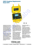
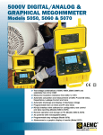
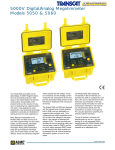
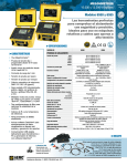
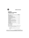
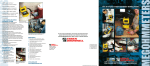
10kV and 15kV Digital Megohmmeters Models 6550 & 6555 Expert tools for testing insulation safely & accurately ►Insulation measurement up to 30TΩ ► Test voltages up to 15,000V ►Step, ramp & fixed voltage testing ►Multiple test modes: voltage ramp and step with “Burn-In”, “Early-Break” and “I-Limit” modes ►3 filter choices to optimize measurement stability ►Selectable voltage from 40V to 10,000 / 15,000V ►Storage of up to 80,000 measurements ►Optically-isolated USB communication for data transfer to PC and report generation using DataView ® software IP 54 Rated Our products are backed by over 100 years of experience in test and measurement equipment, and encompass the latest international standards for quality and safety. Technical Hotline: (800) 343-1391 www.aemc.com Technical Assistance (800) 343-1391 www.aemc.com 1 HIGH-END & PORTABLE Models 6550 & 6555 Model 6555 checking insulation resistance on feed cables to a three-phase motor. The Megohmmeter Models 6550 and 6555 are high-end portable instruments intended for measuring a wide variety of electrical insulation resistance values on cables and devices operating at high voltage. They are packaged in a rugged case that is IP54 rated (cover closed). Test results and configuration information is provided on a graphical LCD screen, as well as exportable through the use of the DataView® software provided. The Megohmmeters can operate on battery or AC power while testing. These Megohmmeters contribute to the safety of electrical installations and equipment. Their operation is managed by microprocessors that acquire, process, display and store the measurements. The Model 6550 makes insulation measurements at voltages up to 10,000V, the Model 6555 up to 15,000V. Main Functions: • Detection and measurement of input voltage, frequency, and current prior to running a test. • Quantitative and qualitative insulation measurements. • Measurements at a fixed test voltage of 500, 1000, 2500, 5000, 10,000 or 15,000Vdc. • Measurements at an adjustable test voltage between 40 and 15,000Vdc preselected by the user prior to the test. Three preselected test voltages can be stored in the instrument and can be modified as needed prior to starting a test. 2 www.aemc.com IP 54 Rated • Ramp voltage measurements with a ramp from 40 to 10,000V or 15,000V, model dependent. Three ramp profiles can be stored in the instrument. Each ramp profile includes the starting and ending test voltage and the ramp time between the two. • Step voltage measurements with steps from 40 to 10,000V or 15,000V, model dependent. Three step voltage profiles can be stored in the instrument. Each contains up to 10 steps that include test voltage and duration. •Three test current choices: Burn-In, Early-Break and I-Limit provide qualitative analysis tools for detection breaks in insulation. •Quality ratio calculations for DAR, PI, and DD are calculated and displayed. •Temperature correction of the measured resistance to a reference temperature. •Capacitance measurement of the device tested. • Residual current measurement. Technical Assistance (800) 343-1391 selectable voltage from 40V to 10kV / 15kV FEATURES APPLICATIONS ►True Megohmmeter® ►Acceptance testing and preventive maintenance ►Fixed or programmable test voltage from 40V to 10kV / 15kV ►Test motors, cables, switchgears and e lectrical wiring installations ► Wide measurement range from 10kΩ to 30TΩ ►Continuity checks ►5mA charging current ►Check domestic and industrial wiring ►Step voltage testing Specifications ►Ramp voltage testing ►Automatic calculation of DAR / PI / DD / ∆R (ppm / V) ratios ►Digital filtering of insulation measurements to eliminate noise and erratic display of the results ►Live measurement of the voltage to warn the operator of potential unsafe conditions MODELS Insulation Tests Test Voltage ►Programmable thresholds to trigger audible alarms which aid the user in fault detection Fixed Test Voltages ►Timed measurement duration checks Variable Voltages 500V 1000V 2500V 5000V 10,000V 15,000V ►Current limit programming ►Fuse protection, with display indication of defective Ramp Mode fuse condition Ramp Configuration Range ►Automatic discharging of the test voltage on the Step Mode tested device at the end of the measurement provides for operator safety ► Auto Power Off mode saves battery power ► Battery charge indication ► Internal storage of up to 80,000 measurements ► Real-time clock ► Large backlit LCD screen with digital display, bargraph and R(t)+u(t), I(t) and I(V) graphs ►Multiple test modes: voltage ramp and step voltage with “Burn-In”, “Early-Break” and “I-Limit” modes ►Three filter settings to optimize measurement stability ►Temperature correction of R at a reference temperature ►Optically-isolated USB communication for transfer onto PC and report generation with FREE DataView® software Technical Assistance (800) 343-1391 Voltage Measurement Capacitance Measurement Leakage Current Measurement Discharge After Test Additional Test Stop Modes I-Limit Early-Break Timer Burn Mode Ratio Calculation Calculation of R at ref. T° Measurement Display Filter Graphs on Display Storage Communication PC Software Power Supply Battery Charging Electrical Safety EMC, Mechanical Protection, Altitude Dimensions/Weight 6550 6555 10kΩ to 2000GΩ (2TΩ) 10kΩ to 4000GΩ (4TΩ) 10kΩ to 10,000GΩ (10TΩ) 10kΩ to 15,000GΩ (15TΩ) 10kΩ to 25,000GΩ (25TΩ) – 10kΩ to 30,000GΩ (30TΩ) 500/1000/2500/ 500/1000/2500/5000/ 5000/10,000V 10,000/15,000V Variable: 40 to 10kV Variable: 40 to 15kV Three user programmable Three user programmable voltage schemes voltage schemes Programmable ramps: start voltage/end voltage/duration 40 to 1100V 40 to 1100V 40 to 10,000V 40 to 15,000V Up to 10 steps (value and duration configurable for each step) 0 to 2500Vac; 0 to 4000Vdc 0.001 to 9.999µF/10.00 to 49.99µF 0 to 8mA Yes/Automatic Programmable: 0.2 to 5mA di/dt Up to 99 minutes 59 seconds Constant testing PI, DAR, DD Yes 3 filters with 3 possible time constants R(t)+V(t); I(t); I(V) 256 registers, stores 80,000 points: R, V, I and date Optically-isolated port for USB and RS232 links DataView® software NiMH rechargeable batteries, two 9.6V/ 4000mAh charging by external voltage: 90 to 260V; 50/60Hz Battery charging allowed while performing insulation measurements 1000V CAT IV; IEC61010-1 and IEC 61557 EN 61326-1, IP54, 2000m 13.39 x 11.81 x 7.87" (340 x 300 x 200mm) approx. 6.2kg (excluding accessories) www.aemc.com 3 CONTROL FEATURES Front Panel Features for Models 6550 & 6555 Models 6550 and 6555 have the same front panel with differences in the display only. Socket for connection to the AC power and recharging of the built-in batteries Large, digital, backlit, graphic LCD screen USB connector for communication to a PC Seven position rotary switch for access to the different modes: fixed voltage, adjustable voltage, ramp and step 5 Safety connection terminals "+", "G" and "-" Test voltage connection terminals Menu navigation buttons START/STOP button to trigger measurement Eight function buttons for access to configuration and graph menus IP 54 Rated E-BRK Test Mode Voltage and Measurement Results Display Area FIXED VOLTAGE 5000V 15000 V Input voltage Frequency Input current Date 2011.05.23 4 www.aemc.com -- V 0.0 V DC 0.2 Hz 42 pA Time 10:11 Display of Supporting Test Results Technical Assistance (800) 343-1391 Functions Models 6550 & 6555 Polarized Index (PI) & Dielectric Absorption X:X Ratio (DAR) Insulation is affected by temperature and humidity variations. Moreover, the appearance of disturbance currents means that the measurement is false right from the start. To eliminate these influences, you have to measure over the long term and calculate the PI and DAR coefficients in order to assess the quality and ageing of the insulation. DD Dielectric Discharge (DD) Automatically detect the presence of faulty insulation layers among other high-resistance layers using the math programmed into the instrument. DD = Current measured after 1 min (mA) Test Voltage (V) x Measured Capacitance (F) V Variable Voltage Selection To handle all measurement environments (electrical equipment, telecommunications installations, rotating machinery, etc.) and measure with the greatest possible accuracy, both instruments offer the V-VAR rotary-switch position. This allows users to select a voltage among three configurable values and then cause it to vary during the test from 40 to 10,000V/15,000V, in 10V steps from 40 to 1000V and in 100V steps above 1kV. Programmable Alarms An alarm threshold can be stored. When the measurement trips the alarm, visual and audible alarms are triggered and displayed. Storage Test with Programmable Duration Insulation measurements sometimes take a long time to stabilize because of transient disturbance currents. Insulation quality can be assessed more accurately by means of long-term measurements and analysis of the insulation’s trend curve according to the time for which the test voltage is applied. Stop Test on Thresholds (l-LIM or di/dt, Early-Break) In order to cover non-destructive test applications, the Models 6550 and 6555 can be set up to stop the tests before breakdown if an insulation fault is detected. The breakdown limit may be a current (I-LIM), or a di/dt value. For investigations on samples, a BURN mode is provided to allow testing whatever the current reached. Graph R(t)+V(t), I(t), I(V) If a test with a programmed duration is run, the instruments automatically store the data at a rate chosen by the user. The Models 6550 and 6555 can display the curves R(t)+V(t), I(t) and I(V) directly on the graphic screen. The curves can also be displayed on a PC screen with the DataView® software. Filter Function When the measurements are unstable, the filter function uses the several filters included in the instrument to smooth the display of the insulation values so that you can read them more easily and interpret them more quickly. Reference Temperature The Models 6550 and 6555 are equipped with internal memory capable of storing up to 80,000 measurements. Two indices, OBJ (object) and TEST, are used to store the time/date-stamped results in an ordered way. Voltage Ramp and Voltage Step The resistance of a faulty insulation falls as the test voltage increases. This test, which involves increasing the test voltage step by step, helps to assess the quality of the insulation by observing the curve R (V test) and the result in ppm/V, which gives a quantitative indication of the curves slope. A ramp mode with a rise time between the two values is also available. Technical Assistance (800) 343-1391 The value of an insulation resistance varies according to the temperature at the time of the measurement. For precise, reliable monitoring, it is always a good idea to express the result of a measurement at a given temperature of reference. There is a special button to press to make the instrument perform the necessary calculation. DataView ® Software This software retrieves the data stored in the memory, plots the trend curve R(t), prints the customized test protocols and creates spreadsheet files. DataView ® configures and controls the instrument via an optically-isolated link compatible with USB and RS232. www.aemc.com 5 FUNCTIONAL Displays The alarm is enabled Test with programmed duration No stop at current limit BURN ALARM FIXED VOLTAGE The blinking value can be modified using the navigation arrow keys 1000 V 500 V Value of the next lowest available test voltage Input voltage Frequency Input current Date 2011.05.23 Current flowing between the terminals GRAPH Measurement function 2500 V Test Run Time 00:02:00 Value of the external voltage present on the terminals and its frequency Battery power level status -0.1 V DC 0.2 Hz 112 pA Time 10:31 Value of the next highest available test voltage nA 700 Programmed duration of the test 600 500 400 300 Date and Time Example of display before measurement. The measurement smoothing filtering is active, with a time constant of 20 seconds DF 20s Value of the insulation resistance ALARM 984 V Stop at current limit 3.244 µA Elapsed Time 00:00:48 Current flowing between the terminals Elapsed time since the beginning of the measurement True value of the test voltage kΩ 1 10 100 Value of the insulation resistance on the bargraph MΩ 1 10 100 GΩ 1 10 100 TΩ 10 ALARM E-BRK 995 MΩ Value of the insulation resistance 528 V True value of the test voltage at the end of the measurement 531 nA Elapsed Time 00:01:12 DAR (30s/60s) PI (1.0m/10m) Capacitance Subsidiary results 1.00 --2.201 nF The type of measurement is a non-destructive test Current at the end of the measurement Duration of the measurement Insulation resistance axis Curve R(t) 508 V 508 V MΩ 3050 3000 500 2950 490 2900 480 2850 Time axis 00:01:00 00:01:00 V 510 3.018 GΩ 3.018 GΩ 0 1:00 2:00 3:00 Resistance versus time graph. 6 www.aemc.com 4kV The bargraph indicates the quality of memory used (in black) and the quantity of memory available (in white). Store Obj. Test 03 01 02 02 02 01 01 02 01 01 MEMORY Date 2011-05-28 2011-05-27 2011-05-27 2011-05-26 2011-05-26 Time 09:04 10:43 10:38 15:04 14:56 Fct. 2550V 1000V 500V The number of measurements that can be recorded depends on the number of samples stored for each measurement. Example of display after measurement. GRAPH 3 The instrument displays the insulation resistance referred to the reference temperature. The insulation resistance is below the alarm threshold RANGE 2 TEMPERATURE Air Temperature 23 °C Humidity 40% Probe Temperature 23 °C Rc Reference Temperature 40 °C ∆T for R/2 10 °C R measured 5.00 GΩ Rc at 40 °C 1.529 GΩ Example of display during measurement. The measurement range is fixed 1 This curve is useful primarily in the case of a measurement in V-RAMP mode. I-LIM 303.3 MΩ The voltage generated is >70VDC and therefore, dangerous 0 Minimum and maximum values of the voltage and the resistance and time at the location of the cursor Test voltage axis Curve V(t), identified by x's CONFIG Total Run Time Manual Stop Manual Stop + DD Timed Run (m:s) Timed Run + DD DAR (s/s) PI (m/m) 00:02:00 2:00 30/60 1.0/10 470 4:00 When Timed Run (test with programmed duration) or Timed Run + DD is selected, the duration of the measurement (m:s) can be set. Technical Assistance (800) 343-1391 Measurement function and availability of samples are indicated. Software & ANALYSIS SCREENS NEW & IMPROVED SOFTWARE Data Analysis & Reporting Software ►Print reports of all test results ►Select test voltage and run tests from your computer with a simple click and execute process ►Capture and display data in real-time ►Retrieve data from the instrument's memory – up to 80,000 insulation resistance measurements ►Display DAR, PI and DD ratios ►Plot graphs of manual and timed tests ►Include your analysis comments section with the report ►Store a library of setups for different applications ►Certification of results through report generation ►Free updates are available @ www.aemc.com Clear and straight forward set up of parameters. Easy identification of all stored test results. Real-time display of measurement results. Technical Assistance (800) 343-1391 Step voltage set up screen. www.aemc.com 7 www.aemc.com Models 6550 & 6555 include: One red, blue and black 9 ft 15kV integral lead, one 15kV jumper lead (blue), one red, blue and black alligator clip (1000V CAT IV), one red and blue test probe (1000V CAT IV), optical USB cable, power cord 115V US, small classic tool bag, user manual and USB stick with DataView® software. ORDERING INFORMATION CATALOG NO. Megohmmeter Model 6550 (Graphical, Analog Bargraph, Backlight, Alarm, Timer, 500V, 1000V, 2500V, 5000V, 10kV, Ramp, StepV, Variable, Auto DAR/PI/DD, USB w/DataView® software) . . . . . . . . . . . . . . . . . . . . . . . . . . . . . . . . . . . . . . . . . . . . Cat. #2130.31. egohmmeter Model 6555 (Graphical, Analog Bargraph, Backlight, Alarm, Timer, 500V, 1000V, 2500V, 5000V, 10kV, M 15kV, Ramp, StepV, Variable, Auto DAR/PI/DD, USB w/DataView® Software). . . . . . . . . . . . . . . . . . . . . . . . . . . . . . . . . . . . . . . Cat. #2130.32 United States & Canada Chauvin Arnoux®, Inc. d.b.a. AEMC ® Instruments 200 Foxborough Blvd. Foxborough, MA 02035 USA (508) 698-2115 • Fax (508) 698-2118 Customer Support for placing an order, obtaining price & delivery [email protected] Sales & Marketing Department for general sales and marketing information [email protected] [email protected] Repair & Calibration Service for information on repair & calibration, obtaining a user manual United States & Canada (continued) Technical & Product Application Support for technical and application support [email protected] Webmaster for information regarding www.aemc.com Australia & New Zealand Chauvin Arnoux®, Inc. d.b.a. AEMC ® Instruments 15 Faraday Drive Dover, NH 03820 USA [email protected] All other countries Chauvin Arnoux® SCA 190, rue Championnet 75876 Paris Cedex 18, France Tel 33 1 44 85 45 28 Fax 33 1 46 27 73 89 [email protected] www.chauvin-arnoux.com [email protected] South America, Central America, Mexico & the Caribbean Chauvin Arnoux®, Inc. d.b.a. AEMC ® Instruments 15 Faraday Drive Dover, NH 03820 USA [email protected] [email protected] Call the AEMC® Instruments Technical Assistance Hotline for immediate consultation with an applications engineer: (800) 343-1391 Chauvin Arnoux®, Inc. d.b.a AEMC® Instruments • 200 Foxborough Blvd. • Foxborough, MA 02035 USA • (800) 343-1391 • (508) 698-2115 • Fax (508) 698-2118 Export Department: (603) 749-6434 ext. 520 • Fax (603) 742-2346 • E-mail: [email protected] 950.BR-6550/6555_1012 Printed in the USA